EP2379435B1 - Verbesserte einzelfalz-ineinanderfaltmaschine und verfahren dafür - Google Patents
Verbesserte einzelfalz-ineinanderfaltmaschine und verfahren dafür Download PDFInfo
- Publication number
- EP2379435B1 EP2379435B1 EP09806009.8A EP09806009A EP2379435B1 EP 2379435 B1 EP2379435 B1 EP 2379435B1 EP 09806009 A EP09806009 A EP 09806009A EP 2379435 B1 EP2379435 B1 EP 2379435B1
- Authority
- EP
- European Patent Office
- Prior art keywords
- cutting
- cut
- stack
- sheets
- web
- Prior art date
- Legal status (The legal status is an assumption and is not a legal conclusion. Google has not performed a legal analysis and makes no representation as to the accuracy of the status listed.)
- Active
Links
Images



Classifications
-
- B—PERFORMING OPERATIONS; TRANSPORTING
- B65—CONVEYING; PACKING; STORING; HANDLING THIN OR FILAMENTARY MATERIAL
- B65H—HANDLING THIN OR FILAMENTARY MATERIAL, e.g. SHEETS, WEBS, CABLES
- B65H45/00—Folding thin material
- B65H45/12—Folding articles or webs with application of pressure to define or form crease lines
- B65H45/24—Interfolding sheets, e.g. cigarette or toilet papers
Definitions
- the present invention relates to an improved interfolding machine of single-fold type, for making paper material, and the like, as packages of interfolded sheets with a predetermined number of sheets.
- the invention relates, furthermore, to an interfolding method therefor.
- Some interfolding machines of known type such as EP982256A1 or US4494741 , provide a couple of folding rollers that supply the interfolded sheets on a stacking table and, in some cases, a plurality of "hands" is provided that alternately conceal within and protrude from special grooves, which are made on the folding rollers for the production of a stack of interfolded sheets on the stacking table.
- a first and a second plurality of separating elements which are arranged for all the length of the stack and at opposite sides with respect to it, enter within the stack same.
- the introduction of the separating elements starts the separation of a formed stack from a growing stack.
- the introduction is provided also of a sheet stretching board.
- the completed stack is then located between the table and the sheet stretching board. While the sheet stretching board remains to support the growing stack, the table drops vertically moving the stack already formed away from the growing stack up to cause the separation of the two stacks.
- interfolding machines of so-called single-fold type, which perform the interfolding process starting from webs of paper that converge towards the folding rollers, have various drawbacks when they are used to make stacks of interfolded sheets that have three panels, so-called "Z" folding.
- Z folding
- a further drawback of the prior art machines is that the first and the last sheet of each stack is torn. Therefore, to avoid that the resulting product has a low quality, it is necessary to provide a very thin tab-bond, which, owing to the other drawbacks as above described, prevents to achieve a high production rate, that is much less than single-fold machines with two or four panel sheets.
- an interfolding machine comprising:
- the first and the second cutting means cut the first and the second web of paper, respectively, in combination with respective counter-cut means that act opposite to the web of paper in order to provide the above described division into the first plurality of sheets and into the second plurality of sheets.
- the first and the second cutting means provide, each, a cutting roller that is peripherally equipped with:
- first and the second cutting means can provide, each, a cutting roller comprising:
- interfolding means are selected from the group comprised of:
- the plurality of cutting blades and the plurality of perforating blades are mounted on the boundary of a cutting roller at respective housings in a way movable selectively between an operating position, in which said blades protrude from said cutting roller and cut the web of paper, and a rest position, in which said blades are withdrawn within said cutting roller and cannot cut the web of paper, said cutting blades and/or perforating blades in said operating positions obtaining a desired cutting configuration.
- a means for actuating selectively each blade of said plurality of cutting blades and/or of said perforating blades between said operating position and said rest position in order to provide a desired cutting configuration.
- the means for actuating selectively each of said cutting blades and each of said perforating blades between said operating position and said rest position can provide an actuator, for example a pneumatic actuator, having a stem with an end that is connected to the blade and the other end that is arranged in an actuating chamber, said blade being pivotally constrained to said roller at a pivoting point, said end of said actuator sliding in said actuating chamber for causing the rotation of said blade about said pivot point and then the movement of said blade from said operating position to said rest position, or vice-versa.
- an actuator for example a pneumatic actuator, having a stem with an end that is connected to the blade and the other end that is arranged in an actuating chamber, said blade being pivotally constrained to said roller at a pivoting point, said end of said actuator sliding in said actuating chamber for causing the rotation of said blade about said pivot point and then the movement of said blade from said operating position to said rest position, or vice-versa.
- the means for actuating the blades between the operating position and the rest position provides a carriage that is integral to each blade and slides on a guide, said carriage withdrawing/forwarding with respect to the boundary of the roller along the guide for bringing the blade from the operating position to the rest position, or vice-versa.
- the means for actuating the blades between the operating position and the rest position comprises a first plurality of blade holders that are arranged peripherally on the roller at the first angle to each other and a second plurality of blade holders that are arranged peripherally on the roller at the second angle to each other, whereby the blades can be mounted on the roller at the first, or the second, plurality of blade holders to provide the complete cuts, or the tear-off lines, respectively.
- first and second separation means are provided that act at opposite sides of the stack and are adapted to be moved between a position that is external to the stack and a position within the stack, said first and second separation means arranged in said position within the stack in points such that the separation of two successive sheets is obtained at a complete cut, or "clean cut".
- the first separation means enters the stack at a cut line, or "clean cut” and the second separation means enters the stack opposite to the first separation means in a position immediately upstream of it. This way, after the separation of two consecutive sheets, between the first and the second separation means only one sheet remains hanging that can be easily stretched for finishing the pack.
- a program means is provided that is adapted to operate electronically said first and second separation means.
- the separation means is operated with high precision.
- the separation means is prevented from entering the stack in wrong points i.e. in points that bridge two "tab-bonds", or between a "tab-bond” and a “clean cut”, and the separation means is caused to enter only at two "clean cuts", as above described.
- a method for making a stack of interfolded sheets comprises the steps of:
- the above described combination of complete cuts, or "clean cuts”, and of tear-off lines, or “tab-bonds” comprises a step of making a cutting line on each of said first and second web of paper alternated to a step of making a tear-off line.
- the step of separating said stack of interfolded sheets from the growing stack is effected by first and second separation means that are adapted to enter the stack, at opposite sides with respect to it, at points of the stack such that the separation of two successive sheets is obtained at a complete cut, or "clean cut".
- an interfolded product comprises a plurality of sheets that are arranged according to a determined interfolded configuration such that two successive sheets of said plurality of sheets are alternately separated by a cut line, or "clean cut", and a tear-off line, or "tab-bond".
- the plurality of interfolded sheets comprises a cut line, or "clean cut”, at the first and the last sheet, and a tear-off line, or “tab bond”, at the sheets that are adjacent to said first and said last sheet. This way, the separation between two stacks is carried out always at the complete cut, or "clean cut”.
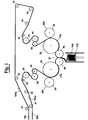
- an interfolding machine for making a stack of interfolded sheets is adapted to move a first web 10a and a second web 10b of a material to interfold, for example paper, non woven fabric, or similar material, respectively along a first direction 101a and along a second direction 101b.
- a material to interfold for example paper, non woven fabric, or similar material
- the two webs of paper 10a and 10b are dragged by respective series of rollers 31-36 and 37-45 up to respective cutting sections 20a and 20b, where cutting rollers 2a and 2b are arranged that in combination with respective counter cutting rollers 3a and 3b cut into sheets the webs of paper 10a and 10b, in order to form respective sequences of sheets 11a and 11b.
- the sequences of sheets 11a and 11b reach then an interfolding section 30, where the sheets 11a that have been obtained by the first web 10a and the sheets 11b that have been obtained by the second web 10b are folded in an interfolded way in order to form a stack 100 having a determined interfolded configuration.
- the cut sheets 11a and 11b which have all the same length, are folded into the interfolded configuration by counterrotating folding rollers 4a, 4b.
- each sheet 11a of a first series of sheets, as they are obtained by cutting web 10a comprises 3 panels I-III, where panels II and III are overlapped to the panels I and II of a sheet 11b of the second series of sheets, as they are obtained by cutting web 10b.
- each series of sheets 11a and 11b has a complete cut 51, or "clean cut”, alternated to a tear-off line 52, or "tab-bond".
- the separation means of two stacks of successive sheets is operated only at two lines of complete cut, or "clean cut".
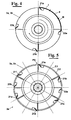
- a possible exemplary embodiment of a cutting roller 2a, or 2b which is capable of providing alternately, a complete cut line, or "clean cut” and a tear-off line, or “tab-bond", on the web of paper 10a, or 10b, in order to provide a stack of interfolded sheets as shown in Fig. 2 , provides a cutting blade 21a and a perforating blade 22a that are arranged at an angle 180° to each other.
- each cutting roller 2a, or 2b comprises a first blade 21a and a second blade 21b, which have a profile that is adapted to cut a complete cutting line of "clean cut” type and are arranged at an angle to each other equal to 180°, and also two perforating blades 22a and 22b, which have a profile that is adapted to cut a tear-off line "tab-bond” type and are arranged at an angle 90° to each other.
- each cutting roller 2a, or 2b has peripherally a first series of blades 21a-21f that are arranged at first angular positions and has a second plurality of blades 22a-22b that are arranged at second angular positions.
- blades 21a-21f of the first series of blades are arranged at a first angle to each other equal to 60° starting from a reference position P0.
- Blade 22a of the second series of blades is arranged at a position P1 at an angle 90° to the actual reference position P0, whereas blade 22b of the second series of blades is arranged at a position P2 at an angle 270° to the actual reference position P0.
- blades 21a-21f of the first series comprise a cutting edge that is adapted to provide a complete cut, or "clean cut", on web 10a, or 10b
- blades 22a and 22b of the second series has a cutting profile that is adapted to provide a tear-off line, or "tab bond”, on web 10a, or 10b.
- Blades 21a-21f of the first series and blades 22a and 22b of the second series are, therefore, operated responsive to the desired interfolded configuration.
- a desire cutting configuration is obtained by arranging selectively blades 21a-21f and 22a and 22b in a cutting/perforating position, in which they protrude from the roller surface 2a, or 2b, and lay in a circumference C1, or in a "neutral" position in which they do not cut/perforate the web of paper 10a, or 10b, and lay in a circumference C2.
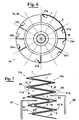
- blades 21a and 21d of the first series of blades are operated to provide a complete cut line, or "clean cut”, on the respective web of paper 10a, or 10b, and blades 22a and 22b of the second series of blades provide a tear-off line 52, or "tab-bond", between two cuts 51 ( Fig. 7 ).
- a separation means is provided that is adapted to pass from a position that is external to the stack to a position within the stack, in which it causes the separation of two consecutive sheets. More precisely, the separation means comprises a first separator 81 and a second separator 82 that act at opposite sides of the stack. When making the separation of two consecutive sheets, separators 81 and 82 enter the stack at points of the stack such that the separation of two successive sheets is obtained at two lines of complete cut, or "clean cut" 51.
- first separator 81 enters stack at a complete cut 51
- separator 82 enters stack in a next upstream position with respect to separator 81, with respect to the conveying direction of the stack ( Fig. 7 ).
- the separation is carried out at the lines of clean cut 51 and after the separation only one panel of a sheet remains free between the two separator 81 and 82.
- a program means is provided that is adapted to operate separators 81 and 82 between the position external to the stack and the position within the stack.
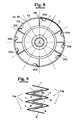
- Blades 21a, 21c and 21e are, in particular, arranged 120° to each other on a respective cutting roller 4a and 4b, and they can be arranged in a cutting position in which they protrude from the boundary thereof.
- the other blades 21b, 21d and 21f of the first series of blades as well as blades 22a and 22b of the second series of blades are arranged in a withdrawn position in which they cannot cut web 10a and 10b. Even in this case, therefore, two successive sheets of each succession of sheets 11a and 11b are separated by a cutting line 51 of "clean cut" type ( Fig. 11 ).
- the interfolding machine as above described, is highly flexible and capable of providing all the different interfolded configurations that can be achieved with machines of "single-fold" type.
- each blade of first series 21a-21f and each blade of second series 22a and 22b is arranged in a recess 203 of either cutting rollers 3a,3b, and is associated with a flexible duct 200 that is in communication with a inflation/deflation device.
- the latter comprises a reversible pump means 205 that is adapted pump a fluid towards/away from flexible duct 200.
- flexible duct 200 when flexible duct 200 is not run by the fluid, it moves to a deflated configuration such that blade 21, or 22, which is associated with it, is brought to a "neutral" position A on circumference C2, in which it does not act on the web of paper ( Fig. 12 ).
- the duct 200 When, instead, the duct 200 is run by the inflation fluid, it turns into an inflated configuration and forces from under the corresponding blade-holder 202 to rotate about a pivot point 201 in order to bring the respective blade 21, or 22, to the cutting position B on circumference C1 in which it acts on the web of paper ( Fig. 13 ).
- An actuator for example a pneumatic actuator, can e provided (not shown) having a stem with an end that is connected to the blade and the other end that is arranged in an actuating chamber.
- the blade is pivotally constrained to the roller at a pivoting point, and the end of the actuator sliding in the actuating chamber for causing the rotation of the blade about the pivot point and then the movement of the blade from the operating position to the rest position, or vice-versa;
- a carriage can be provided that is integral to each blade and slides on a guide, the carriage withdrawing/ forwarding with respect to the boundary of the roller along the guide for bringing the blade from the operating position to the rest position, or vice-versa.
- a first plurality of blade holders are arranged peripherally on the roller at the first angle to each other and a second plurality of blade holders are arranged peripherally on the roller at the second angle to each other, whereby the blades can be selectively mounted on the roller at the first, or the second plurality of blade holders in order to make either the complete cuts, or the tear-off lines, respectively.
Landscapes
- Folding Of Thin Sheet-Like Materials, Special Discharging Devices, And Others (AREA)
- Perforating, Stamping-Out Or Severing By Means Other Than Cutting (AREA)
Claims (13)
- Eine Ineinanderfaltmaschine mit:- einem Zuführabschnitt, der mit einer ersten Vielzahl von Rollen oder Walzen (31-36) zum Bewegen einer ersten Bahn (10a) von Papier und mit einer zweiten Vielzahl von Rollen oder Walzen (37-45) zum Bewegen einer zweiten Bahn (10b) von Papier ausgerüstet ist,- einem Schneidabschnitt mit:- einem ersten Schneidmittel (20a,2a,3a), das eingerichtet ist, um die erste Bahn (10a) von Papier in eine erste Vielzahl von Blättern (11a) abgemessener Länge zu unterteilen,- einem zweiten Schneidmittel (20b,2b,3b), das eingerichtet ist, um die zweite Bahn (10b) von Papier in eine zweite Vielzahl von Blättern (11b) abgemessener Länge zu unterteilen,- einem Ineinanderfaltabschnitt (30) mit:- einem Ineinanderfaltmittel (4a,4b), das eingerichtet ist, um die erste und die zweite Vielzahl von Blättern (11b) in eine vorbestimmte ineinandergefaltete Konfiguration zu falten, um einen Stapel (100) von ineinandergefalteten Blättern zu erhalten;- einem Trennabschnitt (110) zum Abtrennen eines Stapels von ineinandergefalteten Blättern von dem wachsenden Stapel (100),dadurch gekennzeichnet, dass das erste und das zweite Schneidmittel (20a,2a,3a;20b,2b,3b) ein Mittel zum Vorsehen einer Schneidlinie oder eines "sauberen Schnitts" ("Clean-Cut") (51), sowie ein Mittel zum Vorsehen einer Abreißlinie oder einer "Lasahenvexbindung" ("Tab-Bond") (52) an der ersten und der zweiten Bahn (10b) aufweist.
- Ineinanderfaltmaschine gemäß Anspruch 1, wobei das erste und das zweite Schneidmittel (20a;20b) eingerichtet sind, um die erste bzw. die zweite Bahn (10a,10b) von Papier zu schneiden, um eine Schneidlinie oder einen "sauberen Schnitt" ("Clean-Cut") (51) vorzusehen, und ein Mittel zum Vorsehen einer Abreißlinie oder einer "Laschenverbindung" ("Tab-Bond") (52) vorgesehen ist, in Verbindung mit jeweiligen Gegen-Schneidmitteln (2a;2b), die gegenüber der Bahn von Papier (10a,10b) bezüglich dem Schneidmittel (3a;3b) wirken, um den Schnitt zum Ausbilden der ersten Vielzahl von Blättern (11a) und der zweiten Vielzahl von Blättern (11b) auszuführen.
- Ineinanderfaltmaschine gemäß Anspruch 1, wobei das erste und das zweite Schneidmittel (20a,20b) jeweils eine Schneidrolle oder -walze (3a;3b) vorsehen, die am Umfang versehen ist mit:- mindestens einem Schneidmesser (21) mit einem Profil, das eingerichtet ist, um einen vollständigen Schnitt oder einen "sauberen Schnitt" ("Clean-Cut") (51) an einer Bahn von Papier zu schneiden,- mindestens einem Perforiermesser (22) mit einem Profil, das eingerichtet ist, um eine Abreißlinie oder eine "Laschenverbindung" ("Tab-Bond") (52) an der Bahn von Papier zu schneiden.
- Ineinanderfaltmaschine gemäß Anspruch 1, wobei das erste und das zweite Schneidmittel (20a,20b) jeweils eine Schneidrolle oder -walze vorsehen, mit:- einer Vielzahl von Schneidmessern (21a,21b) mit einem Profil, das eingerichtet ist, um einen Schnitt oder einen "sauberen Schnitt" (Clean-Cut) (51) an einer Bahn von Papier zu schneiden, wobei die Schneidmesser (21a,21b) der Vielzahl am Umfang an der Schneidrolle oder -walze (3a,3b) unter einem ersten Winkel zueinander angeordnet sind,- einer Vielzahl von Perforiermessern (22a,22b) mit einem Profil, das eingerichtet ist, um eine Abreißlinie oder eine Laschenverbindung ("Tab-Bond") (52) an der Bahn von Papier zu schneiden, wobei die Perforiermesser (22a,22b) am Umfang an der Schneidrolle oder -walze (3a,3b) unter einem zweiten Winkel zueinander angeordnet sind.
- Ineinanderfaltmaschine gemäß Anspruch 4, wobei die Vielzahl von Schneidmessern (21) und die Vielzahl von Perforiermessern (22) an der Grenze einer Schneidrolle oder - walze (3a,3b) an jeweiligen Gehäusen auf eine Weise befestigt sind, dass sie selektiv zwischen einer Betriebsposition, in der die Messer von der Schneidrolle oder -walze (3a,3b) vorstehen, und einer Ruheposition, in der die Messer in die Schneidrolle oder -walze (3a,3b) zurückgezogen sind, bewegbar sind, wobei die Schneidmesser (21) und/oder die Perforiermesser (22) eingerichtet sind, um an den Betriebspositionen angeordnet zu werden, um eine gewünschte Schneidkonfiguration zu erhalten.
- Ineinanderfaltmaschine gemäß Anspruch 5, wobei ein Mittel vorgesehen ist zum selektiven Betätigen jedes Messers der Vielzahl von Schneidmesser (21a-21f) und der Perforiermesser (22a,22b) zwischen der Betriebsposition und der Ruheposition, um eine gewünschte Schneidkonfiguration zu erhalten.
- Ineinanderfaltmaschine gemäß Anspruch 6, wobei die Mittel zum selektiven Betätigen jedes der Schneidmesser (21a-21f) und jedes der Perforiermesser (22a,22b) zwischen der Betriebsposition und der Ruheposition aus der Gruppe ausgewählt sind, die umfasst:- einen Aktuator, beispielsweise einen pneumatischen Aktuator, mit einem Schaft mit einem Ende, das mit dem Messer verbunden ist, und dem anderen Ende, das in einer Betätigungskammer angeordnet ist, wobei das Messer schwenkbar an der Rolle oder Walze an einem Schwenkpunkt gehalten ist, wobei das Ende des Aktuators in der Betätigungskammer gleitet, um die Drehung des Messers um den Schwenkpunkt und dann die Bewegung des Messers von der Betriebsposition in die Ruheposition oder umgekehrt zu bewirken,- einen flexiblen Kanal (200), der unter den Messern angeordnet und in Verbindung mit einer Inflations-/Deflationseinrichtung (205) ist, die eingerichtet ist, um ein Fluid selektiv zu/weg von dem flexiblen Kanal (200) zu pumpen, derart, dass die Klingen von einer "Neutral"-Position (A), in welcher sie nicht auf die Bahn von Papier einwirken und einer Schneidposition (B), in welcher sie auf die Bahn von Papier einwirken, bewegt werden können,- einen Schlitten, der integral mit jedem Messer ist und an oder auf einer Führung gleitet, wobei der Schlitten sich bezüglich der Grenze der Rolle oder Walze entlang der Führung zurück-/vorbewegt, um das Messer von der Betriebsposition in die Ruheposition oder umgekehrt zu bringen,- eine erste Vielzahl von Messerhaltern, die am Umfang an der Rolle oder Walze unter dem ersten Winkel zueinander angeordnet sind, und eine zweite Vielzahl von Messerhaltern, die am Umfang an der Rolle oder Walze unter dem zweiten Winkel zueinander angeordnet sind, wodurch die Messer an der Rolle oder Walze an der ersten oder der zweiten Vielzahl von Messerhaltern befestigt werden können, um jeweils entweder die vollständigen Schnitte oder die Abreißlinien herzustellen.
- Ineinanderfaltmaschine gemäß Anspruch 1, wobei ein erstes und ein zweites Trennmittel (81,82) vorgesehen und an dem Trennabschnitt (110) angeordnet sind, wobei die ersten und zweiten Trennmittel (81,82) an gegenüberliegenden Seiten bezüglich des Stapels (100) zu wirken, und eingerichtet sind, um zwischen einer Position, die sich extern des Stapels befindet, und einer Position innerhalb des Stapels bewegt zu werden, wobei die ersten und zweiten Trennmittel (81,82) in der Position innerhalb des Stapels an Punkten derart angeordnet sind, dass die Trennung von zwei aufeinanderfolgenden Blättern an einem vollständigen Schnitt oder einem "sauberen Schnitt" ("Clean-Cut") (51) und nicht an einer Abreißlinie (52) erhalten wird.
- Ineinanderfaltmaschine gemäß Anspruch 8, wobei weiterhin ein Programmmittel vorgesehen ist, das eingerichtet ist, um die ersten und zweiten Trennmittel elektronisch zu bestätigen.
- Verfahren zum Herstellen eines Stapels von ineinandergefalteten Blättern mit den Schritten:- Zuführen einer ersten und einer zweiten Bahn (10b) von Papier,- Schneiden der ersten und der zweiten Bahn (10b) von Papier, um jeweils eine erste und eine zweite Vielzahl von Blättern (11b) abgemessener Länge vorzusehen,- Ineinanderfalten der ersten und der zweiten Vielzahl von Blättern (11b) in eine vorbestimmte ineinandergefaltete Konfiguration, um einen Stapel (100) von ineinandergefalteten Blättern zu erhalten,- Abtrennen des Stapels (100) von ineinandergefalteten Blättern von einem wachsenden Stapel und Wegbewegen des Stapels (100),
dadurch gekennzeichnet, dass der Schneidschritt eine Kombination von Schritten des Herstellens vollständiger Schnitte oder von "sauberen Schnitten" ("Clean-Cut") (51) und von Abreißlinien oder Laschenverbindung ("Tab-Bond") an der ersten und der zweiten Bahn (10b) vorsieht. - Verfahren gemäß Anspruch 10, wobei die Kombination von Schritten einen Schritt des Herstellens einer vollständigen Schnittlinie oder eines "sauberen Schnitts" ("Clean-Cut") (51) an jeder der ersten und zweiten Bahn (10b) von Papier abwechselnd mit einem Schritt des Herstellens einer Abreißlinie oder einer "Laschenverbindung" ("Tab-Bond") (52) aufweist.
- Verfahren gemäß Anspruch 10, wobei der Schritt des Abtrennens des Stapels von ineinandergefalteten Blättern von dem wachsenden Stapel mittels erster und zweiter Trennmittel (81,82) ausgeführt wird, die an gegenüberliegenden Seiten des Stapels wirken und eingerichtet sind, um in den Stapel an entsprechenden Punkten des Stapels derart einzutreten, dass sie die Trennung von zwei aufeinanderfolgenden Blättern an zwei Linien eines vollständigen Schnitts oder eines "sauberen Schnitts" ("Clean-Cut" (51) bewirken.
- Ineinandergefaltetes Produkt mit einer Vielzahl von Blättern, die gemäß einer vorbestimmten ineinandergefalteten Konfiguration angeordnet sind, dadurch gekennzeichnet, dass zwei aufeinanderfolgende Blätter der Vielzahl von Blättern (11a,11b) alternierend durch eine Schneidlinie oder einen "sauberen Schnitt" ("Clean-Cut") (51) und eine Abreißlinie oder eine "Laschenverbindung" ("Tab-Bond") getrennt sind.
Priority Applications (1)
| Application Number | Priority Date | Filing Date | Title |
|---|---|---|---|
| EP09806009.8A EP2379435B1 (de) | 2008-12-31 | 2009-12-31 | Verbesserte einzelfalz-ineinanderfaltmaschine und verfahren dafür |
Applications Claiming Priority (3)
| Application Number | Priority Date | Filing Date | Title |
|---|---|---|---|
| EP08173144A EP2204345A1 (de) | 2008-12-31 | 2008-12-31 | Verbesserte Einzelfalzzusammenfaltmaschine und Verfahren dafür |
| PCT/EP2009/009343 WO2010076036A1 (en) | 2008-12-31 | 2009-12-31 | Improved single-fold interfolding machine and method therefor |
| EP09806009.8A EP2379435B1 (de) | 2008-12-31 | 2009-12-31 | Verbesserte einzelfalz-ineinanderfaltmaschine und verfahren dafür |
Publications (2)
| Publication Number | Publication Date |
|---|---|
| EP2379435A1 EP2379435A1 (de) | 2011-10-26 |
| EP2379435B1 true EP2379435B1 (de) | 2013-07-10 |
Family
ID=40671402
Family Applications (2)
| Application Number | Title | Priority Date | Filing Date |
|---|---|---|---|
| EP08173144A Withdrawn EP2204345A1 (de) | 2008-12-31 | 2008-12-31 | Verbesserte Einzelfalzzusammenfaltmaschine und Verfahren dafür |
| EP09806009.8A Active EP2379435B1 (de) | 2008-12-31 | 2009-12-31 | Verbesserte einzelfalz-ineinanderfaltmaschine und verfahren dafür |
Family Applications Before (1)
| Application Number | Title | Priority Date | Filing Date |
|---|---|---|---|
| EP08173144A Withdrawn EP2204345A1 (de) | 2008-12-31 | 2008-12-31 | Verbesserte Einzelfalzzusammenfaltmaschine und Verfahren dafür |
Country Status (4)
| Country | Link |
|---|---|
| US (1) | US20110275503A1 (de) |
| EP (2) | EP2204345A1 (de) |
| ES (1) | ES2430640T3 (de) |
| WO (1) | WO2010076036A1 (de) |
Cited By (3)
| Publication number | Priority date | Publication date | Assignee | Title |
|---|---|---|---|---|
| IT202100022598A1 (it) | 2021-08-31 | 2023-03-03 | Koerber Tissue S P A | Un dispositivo a lame ruotanti, una macchina comprendente detto dispositivo, e metodo |
| IT202200011492A1 (it) | 2022-05-31 | 2023-12-01 | Valmet Tissue Converting S P A | Dispositivo supporto per una lama, dispositivo di taglio o perforazione comprendente il dispositivo di supporto e macchina |
| IT202200011489A1 (it) | 2022-05-31 | 2023-12-01 | Valmet Tissue Converting S P A | Dispositivo di supporto per lame di un gruppo di taglio o perforazione di un materiale nastriforme, e macchina |
Families Citing this family (5)
| Publication number | Priority date | Publication date | Assignee | Title |
|---|---|---|---|---|
| CN107021379B (zh) * | 2011-08-31 | 2018-12-18 | 易希提卫生与保健公司 | 折叠卫生制品的堆叠及其制造方法和装置 |
| TWI665149B (zh) * | 2019-02-01 | 2019-07-11 | 全利機械股份有限公司 | Folding mechanism of fiber products and stacked fiber products thereof |
| TWI760165B (zh) * | 2021-04-01 | 2022-04-01 | 全利機械股份有限公司 | 纖維製品摺疊機構 |
| IT202300021915A1 (it) | 2023-10-20 | 2025-04-20 | Valmet Tissue Converting S R L | Macchina per la trasformazione della carta e prodotto di fogli piegati o interfogliati ottenibile con tale macchina |
| IT202300024255A1 (it) | 2023-11-16 | 2024-02-16 | Ot Lucca S R L | Pacco di fogli interfogliati e metodo e macchina interfogliatrice per produrli |
Family Cites Families (8)
| Publication number | Priority date | Publication date | Assignee | Title |
|---|---|---|---|---|
| US1969480A (en) * | 1931-11-18 | 1934-08-07 | Hoe & Co R | Web cutting mechanism |
| US2626145A (en) * | 1947-04-05 | 1953-01-20 | Int Cellucotton Products | Tissure interfolding method and apparatus |
| US4494741A (en) * | 1981-03-20 | 1985-01-22 | John M. Rudolf | Tissue cutting and interfolding apparatus for Z webs |
| US4691908A (en) * | 1986-01-06 | 1987-09-08 | Paper Converting Machine Company | Apparatus for interfolding |
| US4725469A (en) * | 1987-02-17 | 1988-02-16 | Kimberly-Clark Corporation | Interfolded multi-panel clip |
| JP2575247B2 (ja) * | 1991-11-01 | 1997-01-22 | 克 米山 | 単葉ウエブの多重折畳方法とその装置 |
| EP0982256B1 (de) * | 1998-08-21 | 2008-11-19 | M T C - Macchine Trasformazione Carta S.r.l. | Verfahren zum Ineinanderfalten von luftundurchlässigem oder unzureichend luftdurchlässigem Blattmaterial und Vorrichtung zur Durchführung des Verfahrens |
| US7452321B2 (en) * | 2005-10-07 | 2008-11-18 | C.G. Bretting Manufacturing Company, Inc. | High speed interfolder |
-
2008
- 2008-12-31 EP EP08173144A patent/EP2204345A1/de not_active Withdrawn
-
2009
- 2009-12-31 ES ES09806009T patent/ES2430640T3/es active Active
- 2009-12-31 EP EP09806009.8A patent/EP2379435B1/de active Active
- 2009-12-31 US US13/142,477 patent/US20110275503A1/en not_active Abandoned
- 2009-12-31 WO PCT/EP2009/009343 patent/WO2010076036A1/en not_active Ceased
Cited By (5)
| Publication number | Priority date | Publication date | Assignee | Title |
|---|---|---|---|---|
| IT202100022598A1 (it) | 2021-08-31 | 2023-03-03 | Koerber Tissue S P A | Un dispositivo a lame ruotanti, una macchina comprendente detto dispositivo, e metodo |
| WO2023030839A1 (en) | 2021-08-31 | 2023-03-09 | Körber Tissue S.p.A. | A rotating blade device, a machine comprising said device, and method |
| IT202200011492A1 (it) | 2022-05-31 | 2023-12-01 | Valmet Tissue Converting S P A | Dispositivo supporto per una lama, dispositivo di taglio o perforazione comprendente il dispositivo di supporto e macchina |
| IT202200011489A1 (it) | 2022-05-31 | 2023-12-01 | Valmet Tissue Converting S P A | Dispositivo di supporto per lame di un gruppo di taglio o perforazione di un materiale nastriforme, e macchina |
| WO2023232895A1 (en) | 2022-05-31 | 2023-12-07 | Körber Tissue S.p.A. | Support device for a blade, cutting or perforating device comprising the support device, and machine |
Also Published As
| Publication number | Publication date |
|---|---|
| EP2204345A1 (de) | 2010-07-07 |
| US20110275503A1 (en) | 2011-11-10 |
| EP2379435A1 (de) | 2011-10-26 |
| WO2010076036A1 (en) | 2010-07-08 |
| ES2430640T3 (es) | 2013-11-21 |
Similar Documents
| Publication | Publication Date | Title |
|---|---|---|
| EP2204345A1 (de) | Verbesserte Einzelfalzzusammenfaltmaschine und Verfahren dafür | |
| US8123665B2 (en) | Multi-fold interfolding machine structure | |
| US7998050B2 (en) | Structure of interfolding machine with adjustable cut-off | |
| CA1089504A (en) | Method of lapping webs and product | |
| US4691908A (en) | Apparatus for interfolding | |
| EP2281767B1 (de) | Vorrichtung und Verfahren zum Falten von Flächengebilden | |
| EP2502738B1 (de) | Verbesserte Struktur für eine Papierverarbeitungsmaschine | |
| US7517309B2 (en) | Structure of interfolding machine | |
| US20110230324A1 (en) | Structure of multipurpose sheet folding and stacking machine | |
| US5899447A (en) | Apparatus for stacking pop-up towels | |
| EP0982256B1 (de) | Verfahren zum Ineinanderfalten von luftundurchlässigem oder unzureichend luftdurchlässigem Blattmaterial und Vorrichtung zur Durchführung des Verfahrens | |
| US11629029B2 (en) | Folding, or interfolding, unit for folding, or interfolding sheets of paper for a machine for paper converting | |
| CN112193910A (zh) | 以气流实现纸张半折的折叠机 | |
| US7306554B2 (en) | Method of forming a stack of interfolded sheets of web | |
| CN213864702U (zh) | 以气流实现纸张半折的折叠机 | |
| IT202100030209A1 (it) | Metodo e apparecchiatura per separare due pile successive di fogli interfogliati del tipo uniti da una linea o punto di prefrattura e per ottenere un pacco di fogli interfogliati in cui un foglio estremo del pacco e' ripiegato a definire un lembo di presa per una estrazione facilitata dei fogli dal pacco | |
| EP4034486A1 (de) | Verbesserte zusammenfaltmaschine | |
| IT202300006207A1 (it) | Macchina interfogliatrice per la produzione di materiale cartaceo in pacchetti di fogli interfogliati | |
| WO2025163478A1 (en) | Interfolding machine for producing stacks of interfolded sheets, and method for producing stacks of interfolded sheets |
Legal Events
| Date | Code | Title | Description |
|---|---|---|---|
| PUAI | Public reference made under article 153(3) epc to a published international application that has entered the european phase |
Free format text: ORIGINAL CODE: 0009012 |
|
| 17P | Request for examination filed |
Effective date: 20110721 |
|
| AK | Designated contracting states |
Kind code of ref document: A1 Designated state(s): AT BE BG CH CY CZ DE DK EE ES FI FR GB GR HR HU IE IS IT LI LT LU LV MC MK MT NL NO PL PT RO SE SI SK SM TR |
|
| DAX | Request for extension of the european patent (deleted) | ||
| 17Q | First examination report despatched |
Effective date: 20120608 |
|
| GRAP | Despatch of communication of intention to grant a patent |
Free format text: ORIGINAL CODE: EPIDOSNIGR1 |
|
| GRAS | Grant fee paid |
Free format text: ORIGINAL CODE: EPIDOSNIGR3 |
|
| GRAA | (expected) grant |
Free format text: ORIGINAL CODE: 0009210 |
|
| AK | Designated contracting states |
Kind code of ref document: B1 Designated state(s): AT BE BG CH CY CZ DE DK EE ES FI FR GB GR HR HU IE IS IT LI LT LU LV MC MK MT NL NO PL PT RO SE SI SK SM TR |
|
| REG | Reference to a national code |
Ref country code: GB Ref legal event code: FG4D |
|
| REG | Reference to a national code |
Ref country code: CH Ref legal event code: EP Ref country code: AT Ref legal event code: REF Ref document number: 620866 Country of ref document: AT Kind code of ref document: T Effective date: 20130715 |
|
| REG | Reference to a national code |
Ref country code: IE Ref legal event code: FG4D |
|
| REG | Reference to a national code |
Ref country code: DE Ref legal event code: R096 Ref document number: 602009017118 Country of ref document: DE Effective date: 20130905 |
|
| PG25 | Lapsed in a contracting state [announced via postgrant information from national office to epo] |
Ref country code: SI Free format text: LAPSE BECAUSE OF FAILURE TO SUBMIT A TRANSLATION OF THE DESCRIPTION OR TO PAY THE FEE WITHIN THE PRESCRIBED TIME-LIMIT Effective date: 20130710 |
|
| REG | Reference to a national code |
Ref country code: ES Ref legal event code: FG2A Ref document number: 2430640 Country of ref document: ES Kind code of ref document: T3 Effective date: 20131121 |
|
| REG | Reference to a national code |
Ref country code: AT Ref legal event code: MK05 Ref document number: 620866 Country of ref document: AT Kind code of ref document: T Effective date: 20130710 |
|
| REG | Reference to a national code |
Ref country code: NL Ref legal event code: VDEP Effective date: 20130710 |
|
| REG | Reference to a national code |
Ref country code: LT Ref legal event code: MG4D |
|
| PG25 | Lapsed in a contracting state [announced via postgrant information from national office to epo] |
Ref country code: CY Free format text: LAPSE BECAUSE OF FAILURE TO SUBMIT A TRANSLATION OF THE DESCRIPTION OR TO PAY THE FEE WITHIN THE PRESCRIBED TIME-LIMIT Effective date: 20130724 Ref country code: HR Free format text: LAPSE BECAUSE OF FAILURE TO SUBMIT A TRANSLATION OF THE DESCRIPTION OR TO PAY THE FEE WITHIN THE PRESCRIBED TIME-LIMIT Effective date: 20130710 Ref country code: SE Free format text: LAPSE BECAUSE OF FAILURE TO SUBMIT A TRANSLATION OF THE DESCRIPTION OR TO PAY THE FEE WITHIN THE PRESCRIBED TIME-LIMIT Effective date: 20130710 Ref country code: NO Free format text: LAPSE BECAUSE OF FAILURE TO SUBMIT A TRANSLATION OF THE DESCRIPTION OR TO PAY THE FEE WITHIN THE PRESCRIBED TIME-LIMIT Effective date: 20131010 Ref country code: IS Free format text: LAPSE BECAUSE OF FAILURE TO SUBMIT A TRANSLATION OF THE DESCRIPTION OR TO PAY THE FEE WITHIN THE PRESCRIBED TIME-LIMIT Effective date: 20131110 Ref country code: AT Free format text: LAPSE BECAUSE OF FAILURE TO SUBMIT A TRANSLATION OF THE DESCRIPTION OR TO PAY THE FEE WITHIN THE PRESCRIBED TIME-LIMIT Effective date: 20130710 Ref country code: PT Free format text: LAPSE BECAUSE OF FAILURE TO SUBMIT A TRANSLATION OF THE DESCRIPTION OR TO PAY THE FEE WITHIN THE PRESCRIBED TIME-LIMIT Effective date: 20131111 Ref country code: LT Free format text: LAPSE BECAUSE OF FAILURE TO SUBMIT A TRANSLATION OF THE DESCRIPTION OR TO PAY THE FEE WITHIN THE PRESCRIBED TIME-LIMIT Effective date: 20130710 Ref country code: BE Free format text: LAPSE BECAUSE OF FAILURE TO SUBMIT A TRANSLATION OF THE DESCRIPTION OR TO PAY THE FEE WITHIN THE PRESCRIBED TIME-LIMIT Effective date: 20130710 |
|
| PG25 | Lapsed in a contracting state [announced via postgrant information from national office to epo] |
Ref country code: LV Free format text: LAPSE BECAUSE OF FAILURE TO SUBMIT A TRANSLATION OF THE DESCRIPTION OR TO PAY THE FEE WITHIN THE PRESCRIBED TIME-LIMIT Effective date: 20130710 Ref country code: FI Free format text: LAPSE BECAUSE OF FAILURE TO SUBMIT A TRANSLATION OF THE DESCRIPTION OR TO PAY THE FEE WITHIN THE PRESCRIBED TIME-LIMIT Effective date: 20130710 Ref country code: PL Free format text: LAPSE BECAUSE OF FAILURE TO SUBMIT A TRANSLATION OF THE DESCRIPTION OR TO PAY THE FEE WITHIN THE PRESCRIBED TIME-LIMIT Effective date: 20130710 Ref country code: NL Free format text: LAPSE BECAUSE OF FAILURE TO SUBMIT A TRANSLATION OF THE DESCRIPTION OR TO PAY THE FEE WITHIN THE PRESCRIBED TIME-LIMIT Effective date: 20130710 Ref country code: GR Free format text: LAPSE BECAUSE OF FAILURE TO SUBMIT A TRANSLATION OF THE DESCRIPTION OR TO PAY THE FEE WITHIN THE PRESCRIBED TIME-LIMIT Effective date: 20131011 |
|
| PG25 | Lapsed in a contracting state [announced via postgrant information from national office to epo] |
Ref country code: CY Free format text: LAPSE BECAUSE OF FAILURE TO SUBMIT A TRANSLATION OF THE DESCRIPTION OR TO PAY THE FEE WITHIN THE PRESCRIBED TIME-LIMIT Effective date: 20130710 |
|
| PG25 | Lapsed in a contracting state [announced via postgrant information from national office to epo] |
Ref country code: DK Free format text: LAPSE BECAUSE OF FAILURE TO SUBMIT A TRANSLATION OF THE DESCRIPTION OR TO PAY THE FEE WITHIN THE PRESCRIBED TIME-LIMIT Effective date: 20130710 Ref country code: RO Free format text: LAPSE BECAUSE OF FAILURE TO SUBMIT A TRANSLATION OF THE DESCRIPTION OR TO PAY THE FEE WITHIN THE PRESCRIBED TIME-LIMIT Effective date: 20130710 Ref country code: SK Free format text: LAPSE BECAUSE OF FAILURE TO SUBMIT A TRANSLATION OF THE DESCRIPTION OR TO PAY THE FEE WITHIN THE PRESCRIBED TIME-LIMIT Effective date: 20130710 Ref country code: EE Free format text: LAPSE BECAUSE OF FAILURE TO SUBMIT A TRANSLATION OF THE DESCRIPTION OR TO PAY THE FEE WITHIN THE PRESCRIBED TIME-LIMIT Effective date: 20130710 Ref country code: CZ Free format text: LAPSE BECAUSE OF FAILURE TO SUBMIT A TRANSLATION OF THE DESCRIPTION OR TO PAY THE FEE WITHIN THE PRESCRIBED TIME-LIMIT Effective date: 20130710 |
|
| PLBE | No opposition filed within time limit |
Free format text: ORIGINAL CODE: 0009261 |
|
| STAA | Information on the status of an ep patent application or granted ep patent |
Free format text: STATUS: NO OPPOSITION FILED WITHIN TIME LIMIT |
|
| 26N | No opposition filed |
Effective date: 20140411 |
|
| REG | Reference to a national code |
Ref country code: DE Ref legal event code: R097 Ref document number: 602009017118 Country of ref document: DE Effective date: 20140411 |
|
| REG | Reference to a national code |
Ref country code: CH Ref legal event code: PL |
|
| PG25 | Lapsed in a contracting state [announced via postgrant information from national office to epo] |
Ref country code: LU Free format text: LAPSE BECAUSE OF FAILURE TO SUBMIT A TRANSLATION OF THE DESCRIPTION OR TO PAY THE FEE WITHIN THE PRESCRIBED TIME-LIMIT Effective date: 20131231 |
|
| REG | Reference to a national code |
Ref country code: IE Ref legal event code: MM4A |
|
| PG25 | Lapsed in a contracting state [announced via postgrant information from national office to epo] |
Ref country code: CH Free format text: LAPSE BECAUSE OF NON-PAYMENT OF DUE FEES Effective date: 20131231 Ref country code: IE Free format text: LAPSE BECAUSE OF NON-PAYMENT OF DUE FEES Effective date: 20131231 Ref country code: LI Free format text: LAPSE BECAUSE OF NON-PAYMENT OF DUE FEES Effective date: 20131231 |
|
| PG25 | Lapsed in a contracting state [announced via postgrant information from national office to epo] |
Ref country code: MC Free format text: LAPSE BECAUSE OF FAILURE TO SUBMIT A TRANSLATION OF THE DESCRIPTION OR TO PAY THE FEE WITHIN THE PRESCRIBED TIME-LIMIT Effective date: 20130710 |
|
| PG25 | Lapsed in a contracting state [announced via postgrant information from national office to epo] |
Ref country code: SM Free format text: LAPSE BECAUSE OF FAILURE TO SUBMIT A TRANSLATION OF THE DESCRIPTION OR TO PAY THE FEE WITHIN THE PRESCRIBED TIME-LIMIT Effective date: 20130710 |
|
| PG25 | Lapsed in a contracting state [announced via postgrant information from national office to epo] |
Ref country code: TR Free format text: LAPSE BECAUSE OF FAILURE TO SUBMIT A TRANSLATION OF THE DESCRIPTION OR TO PAY THE FEE WITHIN THE PRESCRIBED TIME-LIMIT Effective date: 20130710 |
|
| PG25 | Lapsed in a contracting state [announced via postgrant information from national office to epo] |
Ref country code: HU Free format text: LAPSE BECAUSE OF FAILURE TO SUBMIT A TRANSLATION OF THE DESCRIPTION OR TO PAY THE FEE WITHIN THE PRESCRIBED TIME-LIMIT; INVALID AB INITIO Effective date: 20091231 Ref country code: BG Free format text: LAPSE BECAUSE OF FAILURE TO SUBMIT A TRANSLATION OF THE DESCRIPTION OR TO PAY THE FEE WITHIN THE PRESCRIBED TIME-LIMIT Effective date: 20130710 Ref country code: MK Free format text: LAPSE BECAUSE OF FAILURE TO SUBMIT A TRANSLATION OF THE DESCRIPTION OR TO PAY THE FEE WITHIN THE PRESCRIBED TIME-LIMIT Effective date: 20130710 |
|
| PG25 | Lapsed in a contracting state [announced via postgrant information from national office to epo] |
Ref country code: MT Free format text: LAPSE BECAUSE OF FAILURE TO SUBMIT A TRANSLATION OF THE DESCRIPTION OR TO PAY THE FEE WITHIN THE PRESCRIBED TIME-LIMIT Effective date: 20130710 |
|
| REG | Reference to a national code |
Ref country code: FR Ref legal event code: PLFP Year of fee payment: 7 |
|
| REG | Reference to a national code |
Ref country code: FR Ref legal event code: PLFP Year of fee payment: 8 |
|
| REG | Reference to a national code |
Ref country code: FR Ref legal event code: PLFP Year of fee payment: 9 |
|
| P01 | Opt-out of the competence of the unified patent court (upc) registered |
Effective date: 20230601 |
|
| PGFP | Annual fee paid to national office [announced via postgrant information from national office to epo] |
Ref country code: GB Payment date: 20251223 Year of fee payment: 17 |
|
| PGFP | Annual fee paid to national office [announced via postgrant information from national office to epo] |
Ref country code: IT Payment date: 20251216 Year of fee payment: 17 |
|
| PGFP | Annual fee paid to national office [announced via postgrant information from national office to epo] |
Ref country code: FR Payment date: 20251223 Year of fee payment: 17 |
|
| PGFP | Annual fee paid to national office [announced via postgrant information from national office to epo] |
Ref country code: ES Payment date: 20260102 Year of fee payment: 17 |
|
| PGFP | Annual fee paid to national office [announced via postgrant information from national office to epo] |
Ref country code: DE Payment date: 20251224 Year of fee payment: 17 |