EP2379435B1 - Improved single-fold interfolding machine and method therefor - Google Patents
Improved single-fold interfolding machine and method therefor Download PDFInfo
- Publication number
- EP2379435B1 EP2379435B1 EP09806009.8A EP09806009A EP2379435B1 EP 2379435 B1 EP2379435 B1 EP 2379435B1 EP 09806009 A EP09806009 A EP 09806009A EP 2379435 B1 EP2379435 B1 EP 2379435B1
- Authority
- EP
- European Patent Office
- Prior art keywords
- cutting
- cut
- stack
- sheets
- web
- Prior art date
- Legal status (The legal status is an assumption and is not a legal conclusion. Google has not performed a legal analysis and makes no representation as to the accuracy of the status listed.)
- Active
Links
- 238000000034 method Methods 0.000 title claims description 9
- 238000000926 separation method Methods 0.000 claims description 43
- 230000007935 neutral effect Effects 0.000 claims description 5
- 239000012530 fluid Substances 0.000 claims description 4
- 238000004891 communication Methods 0.000 claims description 2
- 239000000463 material Substances 0.000 description 5
- 238000004519 manufacturing process Methods 0.000 description 3
- 238000011144 upstream manufacturing Methods 0.000 description 2
- 230000006978 adaptation Effects 0.000 description 1
- 230000001815 facial effect Effects 0.000 description 1
- 230000001788 irregular Effects 0.000 description 1
- 238000012986 modification Methods 0.000 description 1
- 230000004048 modification Effects 0.000 description 1
- 239000004745 nonwoven fabric Substances 0.000 description 1
- 230000002441 reversible effect Effects 0.000 description 1
Images


Classifications
-
- B—PERFORMING OPERATIONS; TRANSPORTING
- B65—CONVEYING; PACKING; STORING; HANDLING THIN OR FILAMENTARY MATERIAL
- B65H—HANDLING THIN OR FILAMENTARY MATERIAL, e.g. SHEETS, WEBS, CABLES
- B65H45/00—Folding thin material
- B65H45/12—Folding articles or webs with application of pressure to define or form crease lines
- B65H45/24—Interfolding sheets, e.g. cigarette or toilet papers
Definitions
- the present invention relates to an improved interfolding machine of single-fold type, for making paper material, and the like, as packages of interfolded sheets with a predetermined number of sheets.
- the invention relates, furthermore, to an interfolding method therefor.
- Some interfolding machines of known type such as EP982256A1 or US4494741 , provide a couple of folding rollers that supply the interfolded sheets on a stacking table and, in some cases, a plurality of "hands" is provided that alternately conceal within and protrude from special grooves, which are made on the folding rollers for the production of a stack of interfolded sheets on the stacking table.
- a first and a second plurality of separating elements which are arranged for all the length of the stack and at opposite sides with respect to it, enter within the stack same.
- the introduction of the separating elements starts the separation of a formed stack from a growing stack.
- the introduction is provided also of a sheet stretching board.
- the completed stack is then located between the table and the sheet stretching board. While the sheet stretching board remains to support the growing stack, the table drops vertically moving the stack already formed away from the growing stack up to cause the separation of the two stacks.
- interfolding machines of so-called single-fold type, which perform the interfolding process starting from webs of paper that converge towards the folding rollers, have various drawbacks when they are used to make stacks of interfolded sheets that have three panels, so-called "Z" folding.
- Z folding
- a further drawback of the prior art machines is that the first and the last sheet of each stack is torn. Therefore, to avoid that the resulting product has a low quality, it is necessary to provide a very thin tab-bond, which, owing to the other drawbacks as above described, prevents to achieve a high production rate, that is much less than single-fold machines with two or four panel sheets.
- an interfolding machine comprising:
- the first and the second cutting means cut the first and the second web of paper, respectively, in combination with respective counter-cut means that act opposite to the web of paper in order to provide the above described division into the first plurality of sheets and into the second plurality of sheets.
- the first and the second cutting means provide, each, a cutting roller that is peripherally equipped with:
- first and the second cutting means can provide, each, a cutting roller comprising:
- interfolding means are selected from the group comprised of:
- the plurality of cutting blades and the plurality of perforating blades are mounted on the boundary of a cutting roller at respective housings in a way movable selectively between an operating position, in which said blades protrude from said cutting roller and cut the web of paper, and a rest position, in which said blades are withdrawn within said cutting roller and cannot cut the web of paper, said cutting blades and/or perforating blades in said operating positions obtaining a desired cutting configuration.
- a means for actuating selectively each blade of said plurality of cutting blades and/or of said perforating blades between said operating position and said rest position in order to provide a desired cutting configuration.
- the means for actuating selectively each of said cutting blades and each of said perforating blades between said operating position and said rest position can provide an actuator, for example a pneumatic actuator, having a stem with an end that is connected to the blade and the other end that is arranged in an actuating chamber, said blade being pivotally constrained to said roller at a pivoting point, said end of said actuator sliding in said actuating chamber for causing the rotation of said blade about said pivot point and then the movement of said blade from said operating position to said rest position, or vice-versa.
- an actuator for example a pneumatic actuator, having a stem with an end that is connected to the blade and the other end that is arranged in an actuating chamber, said blade being pivotally constrained to said roller at a pivoting point, said end of said actuator sliding in said actuating chamber for causing the rotation of said blade about said pivot point and then the movement of said blade from said operating position to said rest position, or vice-versa.
- the means for actuating the blades between the operating position and the rest position provides a carriage that is integral to each blade and slides on a guide, said carriage withdrawing/forwarding with respect to the boundary of the roller along the guide for bringing the blade from the operating position to the rest position, or vice-versa.
- the means for actuating the blades between the operating position and the rest position comprises a first plurality of blade holders that are arranged peripherally on the roller at the first angle to each other and a second plurality of blade holders that are arranged peripherally on the roller at the second angle to each other, whereby the blades can be mounted on the roller at the first, or the second, plurality of blade holders to provide the complete cuts, or the tear-off lines, respectively.
- first and second separation means are provided that act at opposite sides of the stack and are adapted to be moved between a position that is external to the stack and a position within the stack, said first and second separation means arranged in said position within the stack in points such that the separation of two successive sheets is obtained at a complete cut, or "clean cut".
- the first separation means enters the stack at a cut line, or "clean cut” and the second separation means enters the stack opposite to the first separation means in a position immediately upstream of it. This way, after the separation of two consecutive sheets, between the first and the second separation means only one sheet remains hanging that can be easily stretched for finishing the pack.
- a program means is provided that is adapted to operate electronically said first and second separation means.
- the separation means is operated with high precision.
- the separation means is prevented from entering the stack in wrong points i.e. in points that bridge two "tab-bonds", or between a "tab-bond” and a “clean cut”, and the separation means is caused to enter only at two "clean cuts", as above described.
- a method for making a stack of interfolded sheets comprises the steps of:
- the above described combination of complete cuts, or "clean cuts”, and of tear-off lines, or “tab-bonds” comprises a step of making a cutting line on each of said first and second web of paper alternated to a step of making a tear-off line.
- the step of separating said stack of interfolded sheets from the growing stack is effected by first and second separation means that are adapted to enter the stack, at opposite sides with respect to it, at points of the stack such that the separation of two successive sheets is obtained at a complete cut, or "clean cut".
- an interfolded product comprises a plurality of sheets that are arranged according to a determined interfolded configuration such that two successive sheets of said plurality of sheets are alternately separated by a cut line, or "clean cut", and a tear-off line, or "tab-bond".
- the plurality of interfolded sheets comprises a cut line, or "clean cut”, at the first and the last sheet, and a tear-off line, or “tab bond”, at the sheets that are adjacent to said first and said last sheet. This way, the separation between two stacks is carried out always at the complete cut, or "clean cut”.
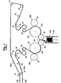
- an interfolding machine for making a stack of interfolded sheets is adapted to move a first web 10a and a second web 10b of a material to interfold, for example paper, non woven fabric, or similar material, respectively along a first direction 101a and along a second direction 101b.
- a material to interfold for example paper, non woven fabric, or similar material
- the two webs of paper 10a and 10b are dragged by respective series of rollers 31-36 and 37-45 up to respective cutting sections 20a and 20b, where cutting rollers 2a and 2b are arranged that in combination with respective counter cutting rollers 3a and 3b cut into sheets the webs of paper 10a and 10b, in order to form respective sequences of sheets 11a and 11b.
- the sequences of sheets 11a and 11b reach then an interfolding section 30, where the sheets 11a that have been obtained by the first web 10a and the sheets 11b that have been obtained by the second web 10b are folded in an interfolded way in order to form a stack 100 having a determined interfolded configuration.
- the cut sheets 11a and 11b which have all the same length, are folded into the interfolded configuration by counterrotating folding rollers 4a, 4b.
- each sheet 11a of a first series of sheets, as they are obtained by cutting web 10a comprises 3 panels I-III, where panels II and III are overlapped to the panels I and II of a sheet 11b of the second series of sheets, as they are obtained by cutting web 10b.
- each series of sheets 11a and 11b has a complete cut 51, or "clean cut”, alternated to a tear-off line 52, or "tab-bond".
- the separation means of two stacks of successive sheets is operated only at two lines of complete cut, or "clean cut".
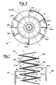
- a possible exemplary embodiment of a cutting roller 2a, or 2b which is capable of providing alternately, a complete cut line, or "clean cut” and a tear-off line, or “tab-bond", on the web of paper 10a, or 10b, in order to provide a stack of interfolded sheets as shown in Fig. 2 , provides a cutting blade 21a and a perforating blade 22a that are arranged at an angle 180° to each other.
- each cutting roller 2a, or 2b comprises a first blade 21a and a second blade 21b, which have a profile that is adapted to cut a complete cutting line of "clean cut” type and are arranged at an angle to each other equal to 180°, and also two perforating blades 22a and 22b, which have a profile that is adapted to cut a tear-off line "tab-bond” type and are arranged at an angle 90° to each other.
- each cutting roller 2a, or 2b has peripherally a first series of blades 21a-21f that are arranged at first angular positions and has a second plurality of blades 22a-22b that are arranged at second angular positions.
- blades 21a-21f of the first series of blades are arranged at a first angle to each other equal to 60° starting from a reference position P0.
- Blade 22a of the second series of blades is arranged at a position P1 at an angle 90° to the actual reference position P0, whereas blade 22b of the second series of blades is arranged at a position P2 at an angle 270° to the actual reference position P0.
- blades 21a-21f of the first series comprise a cutting edge that is adapted to provide a complete cut, or "clean cut", on web 10a, or 10b
- blades 22a and 22b of the second series has a cutting profile that is adapted to provide a tear-off line, or "tab bond”, on web 10a, or 10b.
- Blades 21a-21f of the first series and blades 22a and 22b of the second series are, therefore, operated responsive to the desired interfolded configuration.
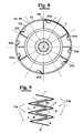
- a desire cutting configuration is obtained by arranging selectively blades 21a-21f and 22a and 22b in a cutting/perforating position, in which they protrude from the roller surface 2a, or 2b, and lay in a circumference C1, or in a "neutral" position in which they do not cut/perforate the web of paper 10a, or 10b, and lay in a circumference C2.
- blades 21a and 21d of the first series of blades are operated to provide a complete cut line, or "clean cut”, on the respective web of paper 10a, or 10b, and blades 22a and 22b of the second series of blades provide a tear-off line 52, or "tab-bond", between two cuts 51 ( Fig. 7 ).
- a separation means is provided that is adapted to pass from a position that is external to the stack to a position within the stack, in which it causes the separation of two consecutive sheets. More precisely, the separation means comprises a first separator 81 and a second separator 82 that act at opposite sides of the stack. When making the separation of two consecutive sheets, separators 81 and 82 enter the stack at points of the stack such that the separation of two successive sheets is obtained at two lines of complete cut, or "clean cut" 51.
- first separator 81 enters stack at a complete cut 51
- separator 82 enters stack in a next upstream position with respect to separator 81, with respect to the conveying direction of the stack ( Fig. 7 ).
- the separation is carried out at the lines of clean cut 51 and after the separation only one panel of a sheet remains free between the two separator 81 and 82.
- a program means is provided that is adapted to operate separators 81 and 82 between the position external to the stack and the position within the stack.
- Blades 21a, 21c and 21e are, in particular, arranged 120° to each other on a respective cutting roller 4a and 4b, and they can be arranged in a cutting position in which they protrude from the boundary thereof.
- the other blades 21b, 21d and 21f of the first series of blades as well as blades 22a and 22b of the second series of blades are arranged in a withdrawn position in which they cannot cut web 10a and 10b. Even in this case, therefore, two successive sheets of each succession of sheets 11a and 11b are separated by a cutting line 51 of "clean cut" type ( Fig. 11 ).
- the interfolding machine as above described, is highly flexible and capable of providing all the different interfolded configurations that can be achieved with machines of "single-fold" type.
- each blade of first series 21a-21f and each blade of second series 22a and 22b is arranged in a recess 203 of either cutting rollers 3a,3b, and is associated with a flexible duct 200 that is in communication with a inflation/deflation device.
- the latter comprises a reversible pump means 205 that is adapted pump a fluid towards/away from flexible duct 200.
- flexible duct 200 when flexible duct 200 is not run by the fluid, it moves to a deflated configuration such that blade 21, or 22, which is associated with it, is brought to a "neutral" position A on circumference C2, in which it does not act on the web of paper ( Fig. 12 ).
- the duct 200 When, instead, the duct 200 is run by the inflation fluid, it turns into an inflated configuration and forces from under the corresponding blade-holder 202 to rotate about a pivot point 201 in order to bring the respective blade 21, or 22, to the cutting position B on circumference C1 in which it acts on the web of paper ( Fig. 13 ).
- An actuator for example a pneumatic actuator, can e provided (not shown) having a stem with an end that is connected to the blade and the other end that is arranged in an actuating chamber.
- the blade is pivotally constrained to the roller at a pivoting point, and the end of the actuator sliding in the actuating chamber for causing the rotation of the blade about the pivot point and then the movement of the blade from the operating position to the rest position, or vice-versa;
- a carriage can be provided that is integral to each blade and slides on a guide, the carriage withdrawing/ forwarding with respect to the boundary of the roller along the guide for bringing the blade from the operating position to the rest position, or vice-versa.
- a first plurality of blade holders are arranged peripherally on the roller at the first angle to each other and a second plurality of blade holders are arranged peripherally on the roller at the second angle to each other, whereby the blades can be selectively mounted on the roller at the first, or the second plurality of blade holders in order to make either the complete cuts, or the tear-off lines, respectively.
Description
- The present invention relates to an improved interfolding machine of single-fold type, for making paper material, and the like, as packages of interfolded sheets with a predetermined number of sheets.
- The invention relates, furthermore, to an interfolding method therefor.
- As well known, in the paper converting industry a variety of types is used of machines and of processes for making paper tissues, paper towels and similar articles as stacks of a certain height of interfolded sheets, for example as described in
EP228687 - They are obtained by folding the sheets in an "interfolded" way, i.e. enclosing within each fold a wing of a previous sheet and a wing a next sheet. This way, when drawing a sheet from the pack, also a wing of the next sheet pops up from the pack, with subsequent practicality of use for certain types of applications. Among possible interfolding ways the L-type, with 2 panels, or the Z or W types, respectively with 3 and 4 panels, are known.
- Some interfolding machines of known type, such as
EP982256A1 US4494741 , provide a couple of folding rollers that supply the interfolded sheets on a stacking table and, in some cases, a plurality of "hands" is provided that alternately conceal within and protrude from special grooves, which are made on the folding rollers for the production of a stack of interfolded sheets on the stacking table. - When the growing stack reaches a predetermined height, a first and a second plurality of separating elements, which are arranged for all the length of the stack and at opposite sides with respect to it, enter within the stack same. The introduction of the separating elements starts the separation of a formed stack from a growing stack.
- Between the separators and the table the introduction is provided also of a sheet stretching board. The completed stack is then located between the table and the sheet stretching board. While the sheet stretching board remains to support the growing stack, the table drops vertically moving the stack already formed away from the growing stack up to cause the separation of the two stacks.
- However, the above described interfolding machines, of so-called single-fold type, which perform the interfolding process starting from webs of paper that converge towards the folding rollers, have various drawbacks when they are used to make stacks of interfolded sheets that have three panels, so-called "Z" folding. In particular, in a pack of "Z" interfolded products, it is necessary that two successive sheets are joined by portions that are separated by cut lines, or "tab-bonds", owing to the odd number of panels.
- The presence of "tab-bonds", which is always necessary in the known single-fold machines for making "Z" type interfolded products, however, complicates remarkably the separation step of a formed stack of sheets from the growing stack, once achieved a desired height of the pack, owing to the need of tearing the tab-bonds during the separation step.
- In particular, when tearing the paper of the tab-bonds an unpredictable movement of the sheet occurs, and irregular folds in the starting and final zone of the pack are formed. Furthermore, for the separation of packs it is necessary to use a sheet stretching board, with relevant structural and operative complications in the machine.
- A further drawback of the prior art machines is that the first and the last sheet of each stack is torn. Therefore, to avoid that the resulting product has a low quality, it is necessary to provide a very thin tab-bond, which, owing to the other drawbacks as above described, prevents to achieve a high production rate, that is much less than single-fold machines with two or four panel sheets.
- For these reasons, this type of machines for making Z-folded sheets has never been used for products of very light paper, like "facial tissue", but only for heavier products, such as paper towels.
- It is therefore a feature of the present invention to provide an interfolding machine that provides an interfolded product of "Z" type that is improved with respect to the similar products of the prior art.
- It is also a feature of the present invention to provide an interfolding machine that allows achieving a higher production rate with respect to the interfolding machines of the prior art.
- It is another feature of the present invention to provide an interfolding machine that is cheap with respect to the interfolding machines of the prior art.
- It is a further feature of the present invention to provide an interfolding machine that is adapted to process a wide variety of different paper material types.
- It is also a feature of the present invention to provide an interfolding machine that is highly flexible, since it is capable of making interfolded products of different types.
- It is also a feature of the present invention to provide an interfolding machine that assists remarkably the separation of two packages of interfolded sheets of "Z" type.
- It is still a feature of the present invention to provide an interfolding machine that is structurally much easier than similar machines of the prior art.
- These and other objects are achieved by an interfolding machine comprising:
- a feeding section equipped with a first plurality of rollers for moving a first web of paper and with a second plurality of rollers for moving a second web of paper;
- a cutting section comprising:
- a first cutting means that is adapted to divide the first web of paper into a first plurality of sheets of measured length;
- a second cutting means that is adapted to divide the second web of paper into a second plurality of sheets of measured length;
- an interfolding section comprising:
- an interfolding means that is adapted to fold said first and said second plurality of sheets into a determined interfolded configuration to obtain a stack of interfolded sheets;
- a separating section for separating a stack of interfolded sheets from the growing stack;
- This way, the machine allows to separate the sheets only at the clean-cut lines, without tearing any tab-bonds.
- Advantageously, the first and the second cutting means cut the first and the second web of paper, respectively, in combination with respective counter-cut means that act opposite to the web of paper in order to provide the above described division into the first plurality of sheets and into the second plurality of sheets.
- Advantageously, the first and the second cutting means provide, each, a cutting roller that is peripherally equipped with:
- at least one cutting blade having a profile that is adapted to cut a complete cut, or "clean cut", on a web of paper;
- at least one perforating blade having a profile that is adapted to cut a tear-off line, or "tab-bond" on the web of paper.
- In particular, the first and the second cutting means can provide, each, a cutting roller comprising:
- a plurality of cutting blades having a profile that is adapted to make a cut, or "clean cut", on a web of paper, said cutting blades of said plurality arranged peripherally on the cutting roller at a first angle to each other;
- a plurality of perforating blades having a profile that is adapted to cut a tear-off line, or "tab-bond", on said web of paper, said perforating blades arranged peripherally on the cutting roller at a second angle to each other.
- Advantageously, the interfolding means are selected from the group comprised of:
- suction holes;
- mechanical clamps;
- a combination thereof.
- In particular, the plurality of cutting blades and the plurality of perforating blades are mounted on the boundary of a cutting roller at respective housings in a way movable selectively between an operating position, in which said blades protrude from said cutting roller and cut the web of paper, and a rest position, in which said blades are withdrawn within said cutting roller and cannot cut the web of paper, said cutting blades and/or perforating blades in said operating positions obtaining a desired cutting configuration.
- Advantageously, a means is provided for actuating selectively each blade of said plurality of cutting blades and/or of said perforating blades between said operating position and said rest position in order to provide a desired cutting configuration.
- In particular, the means for actuating selectively each of said cutting blades and each of said perforating blades between said operating position and said rest position can provide an actuator, for example a pneumatic actuator, having a stem with an end that is connected to the blade and the other end that is arranged in an actuating chamber, said blade being pivotally constrained to said roller at a pivoting point, said end of said actuator sliding in said actuating chamber for causing the rotation of said blade about said pivot point and then the movement of said blade from said operating position to said rest position, or vice-versa.
- Alternatively, the means for actuating the blades between the operating position and the rest position provides a carriage that is integral to each blade and slides on a guide, said carriage withdrawing/forwarding with respect to the boundary of the roller along the guide for bringing the blade from the operating position to the rest position, or vice-versa.
- In a further exemplary embodiment, the means for actuating the blades between the operating position and the rest position comprises a first plurality of blade holders that are arranged peripherally on the roller at the first angle to each other and a second plurality of blade holders that are arranged peripherally on the roller at the second angle to each other, whereby the blades can be mounted on the roller at the first, or the second, plurality of blade holders to provide the complete cuts, or the tear-off lines, respectively.
- In particular, at the separating section first and second separation means are provided that act at opposite sides of the stack and are adapted to be moved between a position that is external to the stack and a position within the stack, said first and second separation means arranged in said position within the stack in points such that the separation of two successive sheets is obtained at a complete cut, or "clean cut".
- More precisely, the first separation means enters the stack at a cut line, or "clean cut" and the second separation means enters the stack opposite to the first separation means in a position immediately upstream of it. This way, after the separation of two consecutive sheets, between the first and the second separation means only one sheet remains hanging that can be easily stretched for finishing the pack.
- Advantageously, furthermore, a program means is provided that is adapted to operate electronically said first and second separation means. This way, the separation means is operated with high precision. This way, furthermore, the separation means is prevented from entering the stack in wrong points i.e. in points that bridge two "tab-bonds", or between a "tab-bond" and a "clean cut", and the separation means is caused to enter only at two "clean cuts", as above described.
- According to another aspect of the invention, a method for making a stack of interfolded sheets comprises the steps of:
- feeding a first and a second web of paper;
- cutting the first and the second web of paper in order to provide a first and a second plurality of sheets of measured length, respectively;
- interfolding the first and the second plurality of sheets into a determined interfolded configuration to obtain a stack of interfolded sheets;
- separating said stack of interfolded sheets from the growing stack and moving away the stack;
- This way, the separation of the stacks is carried out only at the clean-cut lines, without tearing, and with simplification of the steps of separation, such that the separation between the formed stack and the growing stack does not require using separation boards for tearing the tab-bonds, since at the clean-cut the separation between the two stacks is obtained freely.
- In particular, the above described combination of complete cuts, or "clean cuts", and of tear-off lines, or "tab-bonds" comprises a step of making a cutting line on each of said first and second web of paper alternated to a step of making a tear-off line.
- Advantageously, the step of separating said stack of interfolded sheets from the growing stack is effected by first and second separation means that are adapted to enter the stack, at opposite sides with respect to it, at points of the stack such that the separation of two successive sheets is obtained at a complete cut, or "clean cut".
- According to a further aspect of the invention, an interfolded product comprises a plurality of sheets that are arranged according to a determined interfolded configuration such that two successive sheets of said plurality of sheets are alternately separated by a cut line, or "clean cut", and a tear-off line, or "tab-bond".
- In particular, the plurality of interfolded sheets comprises a cut line, or "clean cut", at the first and the last sheet, and a tear-off line, or "tab bond", at the sheets that are adjacent to said first and said last sheet. This way, the separation between two stacks is carried out always at the complete cut, or "clean cut".
- Further characteristic and the advantages of the interfolding machine, according to the invention, will be made clearer with the following description of an exemplary embodiment thereof, exemplifying but not limitative, with reference to the attached drawings, in which like reference characters designate the same or similar parts, throughout the figures of which:
-
figure 1 diagrammatically shows an elevational side view of an interfolding machine, according to the invention, for making packages of interfolded sheets; -
figure 2 shows in detail an elevational front view of a stack of interfolded sheets of "Z" type obtained with the machine ofFig. 1 ; - figures from 3 to 5 show elevational side views of three possible exemplary embodiments of a cutting roller according to the invention;
-
figure 6 shows an elevational side view of the cutting roller ofFig. 5 in a first cutting configuration; -
figure 7 diagrammatically shows an elevational side view of a stack of interfolded sheets as it is obtained with the cutting configuration ofFig. 6 ; -
figure 8 shows an elevational side view of the cutting roller ofFig. 5 in a second cutting configuration; -
figure 9 diagrammatically shows an elevational side view of a stack of interfolded sheets as it is obtained with the cutting configuration ofFig. 8 ; -
figure 10 shows an elevational side view of the cutting roller ofFig. 5 in a third cutting configuration; -
figure 11 diagrammatically shows an elevational side view of a stack of interfolded sheets as it is obtained with the cutting configuration ofFig. 10 ; -
figures 12 and 13 show in detail a possible device of handling the blades of the cutting roller ofFig. 5 between a cutting position and a neutral position. - With reference to
Fig. 1 , an interfolding machine for making a stack of interfolded sheets is adapted to move afirst web 10a and asecond web 10b of a material to interfold, for example paper, non woven fabric, or similar material, respectively along afirst direction 101a and along asecond direction 101b. - More precisely, the two webs of
paper respective cutting sections rollers counter cutting rollers paper sheets - The sequences of
sheets interfolding section 30, where thesheets 11a that have been obtained by thefirst web 10a and thesheets 11b that have been obtained by thesecond web 10b are folded in an interfolded way in order to form astack 100 having a determined interfolded configuration. - In particular, at the
interfolding section 30, thecut sheets folding rollers - With reference to
Fig. 2 , in astack 100 of interfolded sheets of "Z" type, eachsheet 11a of a first series of sheets, as they are obtained by cuttingweb 10a, comprises 3 panels I-III, where panels II and III are overlapped to the panels I and II of asheet 11b of the second series of sheets, as they are obtained by cuttingweb 10b. - According to the invention, each series of
sheets complete cut 51, or "clean cut", alternated to a tear-off line 52, or "tab-bond". - The above described configuration avoids the above described drawbacks of the prior art machines, that are due to the separation of two successive sheets of two different stacks that are joined by a line of "tab-bond" type.
- In fact, according to the invention, the separation means of two stacks of successive sheets is operated only at two lines of complete cut, or "clean cut".
- With reference to
Fig. 3 , a possible exemplary embodiment of a cuttingroller paper Fig. 2 , provides acutting blade 21a and aperforating blade 22a that are arranged at an angle 180° to each other. - Alternatively, as shown in
figure 4 , each cuttingroller first blade 21a and asecond blade 21b, which have a profile that is adapted to cut a complete cutting line of "clean cut" type and are arranged at an angle to each other equal to 180°, and also two perforatingblades - In a further exemplary embodiment that is shown in
Fig. 5 , each cuttingroller blades 21a-21f that are arranged at first angular positions and has a second plurality ofblades 22a-22b that are arranged at second angular positions. - More precisely,
blades 21a-21f of the first series of blades are arranged at a first angle to each other equal to 60° starting from a reference position P0.Blade 22a of the second series of blades is arranged at a position P1 at an angle 90° to the actual reference position P0, whereasblade 22b of the second series of blades is arranged at a position P2 at an angle 270° to the actual reference position P0. - More in detail,
blades 21a-21f of the first series comprise a cutting edge that is adapted to provide a complete cut, or "clean cut", onweb blades web -
Blades 21a-21f of the first series andblades - In this case, by operating selectively the blades of the
first series 21a-21f and/or the blades of thesecond series blades 21a-21f and 22a and 22b in a cutting/perforating position, in which they protrude from theroller surface paper - For example, as shown in
Fig. 6 , in order to make an interfolded configuration of "Z" type,blades paper blades off line 52, or "tab-bond", between two cuts 51 (Fig. 7 ). - In particular, a separation means is provided that is adapted to pass from a position that is external to the stack to a position within the stack, in which it causes the separation of two consecutive sheets. More precisely, the separation means comprises a
first separator 81 and asecond separator 82 that act at opposite sides of the stack. When making the separation of two consecutive sheets,separators - In particular,
first separator 81 enters stack at acomplete cut 51, whereasseparator 82 enters stack in a next upstream position with respect toseparator 81, with respect to the conveying direction of the stack (Fig. 7 ). This way, the separation is carried out at the lines ofclean cut 51 and after the separation only one panel of a sheet remains free between the twoseparator separators - In case of an "L" type interfolded configuration, instead, where two
sheets sheets 11 of the stack are separated by a complete cut, or "clean cut" 51 (Fig. 9 ). - Therefore, in this case all the six blades of "clean cut" type of each
roller blades Fig. 8 ). - If, instead, an interfolded "W" configuration has to be obtained, where two
successive sheets Fig. 11 ), onlyblades roller Fig. 10 ) are operated.Blades respective cutting roller other blades blades web sheets line 51 of "clean cut" type (Fig. 11 ). - Therefore, the interfolding machine, as above described, is highly flexible and capable of providing all the different interfolded configurations that can be achieved with machines of "single-fold" type.
- In
Figs. 12 and 13 a possible device is diagrammatically shown that can be used for bringing each blade offirst series 21a-21f and each blade ofsecond series first series 21a-21f and ofsecond series rollers flexible duct 200 that is in communication with a inflation/deflation device. The latter comprises a reversible pump means 205 that is adapted pump a fluid towards/away fromflexible duct 200. - More in detail, when
flexible duct 200 is not run by the fluid, it moves to a deflated configuration such that blade 21, or 22, which is associated with it, is brought to a "neutral" position A on circumference C2, in which it does not act on the web of paper (Fig. 12 ). - When, instead, the
duct 200 is run by the inflation fluid, it turns into an inflated configuration and forces from under the corresponding blade-holder 202 to rotate about apivot point 201 in order to bring the respective blade 21, or 22, to the cutting position B on circumference C1 in which it acts on the web of paper (Fig. 13 ). - Alternative devices for actuating the blades can be provided as alternative mechanical implementations obvious to a skilled person.
- An actuator, for example a pneumatic actuator, can e provided (not shown) having a stem with an end that is connected to the blade and the other end that is arranged in an actuating chamber. The blade is pivotally constrained to the roller at a pivoting point, and the end of the actuator sliding in the actuating chamber for causing the rotation of the blade about the pivot point and then the movement of the blade from the operating position to the rest position, or vice-versa;
- In a further alternative (not shown) a carriage can be provided that is integral to each blade and slides on a guide, the carriage withdrawing/ forwarding with respect to the boundary of the roller along the guide for bringing the blade from the operating position to the rest position, or vice-versa.
- In still another alternative (not shown) a first plurality of blade holders are arranged peripherally on the roller at the first angle to each other and a second plurality of blade holders are arranged peripherally on the roller at the second angle to each other, whereby the blades can be selectively mounted on the roller at the first, or the second plurality of blade holders in order to make either the complete cuts, or the tear-off lines, respectively.
- The foregoing description of a specific embodiment will so fully reveal the invention according to the conceptual point of view, so that others, by applying current knowledge, will be able to modify and/or adapt for various applications such an embodiment without further research and without parting from the invention, and it is therefore to be understood that such adaptations and modifications will have to be considered as equivalent to the specific embodiment. The means and the materials to realise the different functions described herein could have a different nature without, for this reason, departing from the field of the invention. It is to be understood that the phraseology or terminology employed herein is for the purpose of description and not of limitation.
Claims (13)
- Interfolding machine comprising:- a feeding section equipped with a first plurality of rollers (31-36) for moving a first web (10a) of paper and with a second plurality of rollers (37-45) for moving a second web (10b) of paper;- a cutting section comprising:- a first cutting means (20a, 2a, 3a) that is adapted to divide the first web (10a) of paper into a first plurality of sheets (11a) of measured length;- a second cutting means (20b, 2b, 3b) that is adapted to divide the second web (10b) of paper into a second plurality of sheets (11b) of measured length;- an interfolding section (30) comprising:- an interfolding means (4a, 4b) that is adapted to fold said first and said second plurality of sheets (11b) into a determined interfolded configuration to obtain a stack (100) of interfolded sheets;- a separating section (110) for separating a stack of interfolded sheets from the growing stack (100) ;
characterised in that said first and said second cutting means (20a, 2a, 3a; 20b, 2b, 3b) comprises a means to provide a cut line, or "clean-cut" (51), and a means to provide a tear-off line, or "tab-bond" (52), on said first and said second web (10b). - Interfolding machine, according to claim 1, wherein said first and said second cutting means (20a; 20b) are adapted to cut said first and said second web (10a,10b) of paper, respectively, to provide a cut line, or "clean-cut" (51), and a means to provide a tear-off line, or "tab-bond" (52), in combination with respective counter-cut means (2a; 2b) that act opposite to said web of paper (10a, 10b) with respect to said cutting means (3a; 3b) to make said cut to form said first plurality of sheets (11a) and said second plurality of sheets (11b).
- Interfolding machine according to claim 1, wherein the first and the second cutting means (20a, 20b) provide, each, a cutting roller (3a; 3b) that is peripherally equipped with:- at least one cutting blade (21) having a profile that is adapted to cut a complete cut, or "clean cut" (51), on a web of paper;- at least one perforating blade (22) having a profile that is adapted to cut a tear-off line, or "tab-bond" (52) on the web of paper.
- Interfolding machine according to claim 1, wherein said first and the second cutting means (20a, 20b) provide each a cutting roller comprising:- a plurality of cutting blades (21a, 21b) having a profile that is adapted to make a cut, or "clean cut" (51), on a web of paper, said cutting blades (21a, 21b) of said plurality arranged peripherally on the cutting roller (3a,3b) at a first angle to each other;- a plurality of perforating blades (22a,22b) having a profile that is adapted to cut a tear-off line, or "tab-bond" (52), on said web of paper, said perforating blades (22a,22b) arranged peripherally on the cutting roller (3a,3b) at a second angle to each other.
- Interfolding machine according to claim 4, wherein said plurality of cutting blades (21) and said plurality of perforating blades (22) are mounted on the boundary of a cutting roller (3a,3b) at respective housings in a way movable selectively between an operating position, in which said blades protrude from said cutting roller (3a,3b), and a rest position, in which said blades are withdrawn within said cutting roller (3a,3b), said cutting blades (21) and/or perforating blades (22) adapted to be arranged at said operating positions obtaining a desired cutting configuration.
- Interfolding machine according to claim 5, wherein a means is provided for actuating selectively each blade of said plurality of cutting blades (21a-21f) and of said perforating blades (22a,22b) between said operating position and said rest position in order to provide a desired cutting configuration.
- Interfolding machine according to claim 6, wherein said means for actuating selectively each of said cutting blades (21a-21f) and each of said perforating blades (22a,22b) between said operating position and said rest position, are selected from the group comprised of:- an actuator, for example a pneumatic actuator, having a stem with an end that is connected to the blade and the other end that is arranged in an actuating chamber, said blade being pivotally constrained to said roller at a pivoting point, said end of said actuator sliding in said actuating chamber for causing the rotation of said blade about said pivot point and then the movement of said blade from said operating position to said rest position, or vice-versa;- a flexible duct (200) that is arranged under said blades and is in communication with a inflation/deflation (205) that is adapted to selectively pump a fluid towards/away from the flexible duct (200), such that the blades can be moved from a "neutral" position (A) in which it does not act on the web of paper, and a cutting position (B) in which it acts on the web of paper;- a carriage that is integral to each blade and slides on a guide, said carriage withdrawing/forwarding with respect to the boundary of said roller along said guide for bringing said blade from said operating position to said rest position, or vice-versa;- a first plurality of blade holders that are arranged peripherally on said roller at said first angle to each other and a second plurality of blade holders that are arranged peripherally on said roller at said second angle to each other, whereby said blades can be mounted on said roller at said first, or said second plurality of blade holders in order to make either said complete cuts, or said tear-off lines, respectively.
- Interfolding machine according to claim 1, wherein, a first and second separation means (81, 82) are provided arranged at said separating section (110), said first and second separation means (81, 82) acting at opposite sides with respect to the stack (100) and adapted to be moved between a position that is external to the stack and a position within the stack, said first and second separation means (81, 82) arranged in said position within the stack in points such that the separation of two successive sheets is obtained at a complete cut, or "clean cut" (51) and not at a tear-off line (52).
- Interfolding machine according to claim 8, wherein, furthermore, a program means is provided that is adapted to operate electronically said first and second separation means.
- Method for making a stack of interfolded sheets comprising the steps of:- feeding a first and a second web (10b) of paper;- cutting said first and said second web (10b) of paper in order to provide a first and a second plurality of sheets (11b) of measured length, respectively;- interfolding said first and said second plurality of sheets (11b) into a determined interfolded configuration to obtain a stack (100) of interfolded sheets;- separating said stack (100) of interfolded sheets from a growing stack and moving away the stack (100); characterised in that said cutting step provides a combination of steps of making complete cuts, or "clean cut" (51), and tear-off lines, or "tab bond" on said first and second web (10b).
- Method, according to claim 10, wherein said combination of steps comprises a step of making a complete cut line, or "clean cut" (51), on each of said first and second web (10b) of paper alternated to a step of making a tear-off line, or "tab-bond" (52).
- Method, according to claim 10, wherein said step of separating said stack of interfolded sheets from the growing stack is effected by means of first and second separation means (81,82) that act at opposite sides of the stack and are adapted to enter the stack in corresponding points of the stack such that they cause the separation of two successive sheets at two lines of complete cut, or "clean cut" (51).
- Interfolded product comprising a plurality of sheets that are arranged according to a determined interfolded configuration characterised in that two successive sheets of said plurality of sheets (11a,11b) are alternately separated by a cut line, or "clean cut" (51), and a tear-off line, or "tab bond".
Priority Applications (1)
| Application Number | Priority Date | Filing Date | Title |
|---|---|---|---|
| EP09806009.8A EP2379435B1 (en) | 2008-12-31 | 2009-12-31 | Improved single-fold interfolding machine and method therefor |
Applications Claiming Priority (3)
| Application Number | Priority Date | Filing Date | Title |
|---|---|---|---|
| EP08173144A EP2204345A1 (en) | 2008-12-31 | 2008-12-31 | Improved single-fold interfolding machine and method therefor |
| PCT/EP2009/009343 WO2010076036A1 (en) | 2008-12-31 | 2009-12-31 | Improved single-fold interfolding machine and method therefor |
| EP09806009.8A EP2379435B1 (en) | 2008-12-31 | 2009-12-31 | Improved single-fold interfolding machine and method therefor |
Publications (2)
| Publication Number | Publication Date |
|---|---|
| EP2379435A1 EP2379435A1 (en) | 2011-10-26 |
| EP2379435B1 true EP2379435B1 (en) | 2013-07-10 |
Family
ID=40671402
Family Applications (2)
| Application Number | Title | Priority Date | Filing Date |
|---|---|---|---|
| EP08173144A Withdrawn EP2204345A1 (en) | 2008-12-31 | 2008-12-31 | Improved single-fold interfolding machine and method therefor |
| EP09806009.8A Active EP2379435B1 (en) | 2008-12-31 | 2009-12-31 | Improved single-fold interfolding machine and method therefor |
Family Applications Before (1)
| Application Number | Title | Priority Date | Filing Date |
|---|---|---|---|
| EP08173144A Withdrawn EP2204345A1 (en) | 2008-12-31 | 2008-12-31 | Improved single-fold interfolding machine and method therefor |
Country Status (4)
| Country | Link |
|---|---|
| US (1) | US20110275503A1 (en) |
| EP (2) | EP2204345A1 (en) |
| ES (1) | ES2430640T3 (en) |
| WO (1) | WO2010076036A1 (en) |
Cited By (2)
| Publication number | Priority date | Publication date | Assignee | Title |
|---|---|---|---|---|
| IT202100022598A1 (en) | 2021-08-31 | 2023-03-03 | Koerber Tissue S P A | A ROTATING BLADE DEVICE, A MACHINE INCLUDING SUCH DEVICE, AND METHOD |
| WO2023232895A1 (en) | 2022-05-31 | 2023-12-07 | Körber Tissue S.p.A. | Support device for a blade, cutting or perforating device comprising the support device, and machine |
Families Citing this family (3)
| Publication number | Priority date | Publication date | Assignee | Title |
|---|---|---|---|---|
| BR112014004355A2 (en) | 2011-08-31 | 2017-03-28 | Sca Hygiene Prod Ab | stack of folded toiletries and method and apparatus to produce the same |
| TWI665149B (en) * | 2019-02-01 | 2019-07-11 | 全利機械股份有限公司 | Folding mechanism of fiber products and stacked fiber products |
| TWI760165B (en) * | 2021-04-01 | 2022-04-01 | 全利機械股份有限公司 | Fiber Products Folding Mechanism |
Family Cites Families (8)
| Publication number | Priority date | Publication date | Assignee | Title |
|---|---|---|---|---|
| US1969480A (en) * | 1931-11-18 | 1934-08-07 | Hoe & Co R | Web cutting mechanism |
| US2626145A (en) * | 1947-04-05 | 1953-01-20 | Int Cellucotton Products | Tissure interfolding method and apparatus |
| US4494741A (en) * | 1981-03-20 | 1985-01-22 | John M. Rudolf | Tissue cutting and interfolding apparatus for Z webs |
| US4691908A (en) * | 1986-01-06 | 1987-09-08 | Paper Converting Machine Company | Apparatus for interfolding |
| US4725469A (en) * | 1987-02-17 | 1988-02-16 | Kimberly-Clark Corporation | Interfolded multi-panel clip |
| JP2575247B2 (en) * | 1991-11-01 | 1997-01-22 | 克 米山 | Method and apparatus for multiple folding of single leaf web |
| DE69840232D1 (en) * | 1998-08-21 | 2009-01-02 | Mtc Macchine Trasformazione | A method of interfolding air impermeable or insufficient air permeable sheet material and apparatus for carrying out the method |
| US7452321B2 (en) * | 2005-10-07 | 2008-11-18 | C.G. Bretting Manufacturing Company, Inc. | High speed interfolder |
-
2008
- 2008-12-31 EP EP08173144A patent/EP2204345A1/en not_active Withdrawn
-
2009
- 2009-12-31 ES ES09806009T patent/ES2430640T3/en active Active
- 2009-12-31 WO PCT/EP2009/009343 patent/WO2010076036A1/en active Application Filing
- 2009-12-31 US US13/142,477 patent/US20110275503A1/en not_active Abandoned
- 2009-12-31 EP EP09806009.8A patent/EP2379435B1/en active Active
Cited By (3)
| Publication number | Priority date | Publication date | Assignee | Title |
|---|---|---|---|---|
| IT202100022598A1 (en) | 2021-08-31 | 2023-03-03 | Koerber Tissue S P A | A ROTATING BLADE DEVICE, A MACHINE INCLUDING SUCH DEVICE, AND METHOD |
| WO2023030839A1 (en) | 2021-08-31 | 2023-03-09 | Körber Tissue S.p.A. | A rotating blade device, a machine comprising said device, and method |
| WO2023232895A1 (en) | 2022-05-31 | 2023-12-07 | Körber Tissue S.p.A. | Support device for a blade, cutting or perforating device comprising the support device, and machine |
Also Published As
| Publication number | Publication date |
|---|---|
| ES2430640T3 (en) | 2013-11-21 |
| US20110275503A1 (en) | 2011-11-10 |
| WO2010076036A1 (en) | 2010-07-08 |
| EP2379435A1 (en) | 2011-10-26 |
| EP2204345A1 (en) | 2010-07-07 |
Similar Documents
| Publication | Publication Date | Title |
|---|---|---|
| US8123665B2 (en) | Multi-fold interfolding machine structure | |
| EP1826165B1 (en) | Modular interfolding machine allowing simple format change | |
| US7517309B2 (en) | Structure of interfolding machine | |
| EP2379435B1 (en) | Improved single-fold interfolding machine and method therefor | |
| CA1089504A (en) | Method of lapping webs and product | |
| EP2281767B1 (en) | Sheet folding apparatus and method | |
| US4691908A (en) | Apparatus for interfolding | |
| EP2502738B1 (en) | Improved structure of paper converting machine | |
| US7306554B2 (en) | Method of forming a stack of interfolded sheets of web | |
| US5899447A (en) | Apparatus for stacking pop-up towels | |
| US20110230324A1 (en) | Structure of multipurpose sheet folding and stacking machine | |
| EP0982256B1 (en) | Interfolding method of sheet material not or not enough permeable to air and machine for carrying out such method | |
| WO2016049338A1 (en) | Interfolder and separator arrangement and methods of separating a stack of sheets from a continuously building stream of sheets | |
| US11629029B2 (en) | Folding, or interfolding, unit for folding, or interfolding sheets of paper for a machine for paper converting | |
| CN213864702U (en) | Folding machine for realizing half-folding of paper by airflow | |
| CN112193910A (en) | Folding machine for realizing half-folding of paper by airflow | |
| EP3393950B1 (en) | Folding or interfolding machine, and sheet conveying unit for paper converting machines | |
| IT202100030209A1 (en) | METHOD AND EQUIPMENT FOR SEPARATE TWO SUBSEQUENT PILES OF INTERLEAVED SHEETS OF THE TYPE JOINED BY A PRE-FRACTURE LINE OR POINT AND TO OBTAIN A PACK OF INTERLEAVED SHEETS IN WHICH ONE END SHEET OF THE PACKAGE IS FOLDED TO DEFINE A GRIP FLAP FOR EASY EXTRACTION OF THE LEAVES FROM THE PACKAGE | |
| EP4034486A1 (en) | Improved interfolding machine | |
| AU2382599A (en) | Folded towel stack |
Legal Events
| Date | Code | Title | Description |
|---|---|---|---|
| PUAI | Public reference made under article 153(3) epc to a published international application that has entered the european phase |
Free format text: ORIGINAL CODE: 0009012 |
|
| 17P | Request for examination filed |
Effective date: 20110721 |
|
| AK | Designated contracting states |
Kind code of ref document: A1 Designated state(s): AT BE BG CH CY CZ DE DK EE ES FI FR GB GR HR HU IE IS IT LI LT LU LV MC MK MT NL NO PL PT RO SE SI SK SM TR |
|
| DAX | Request for extension of the european patent (deleted) | ||
| 17Q | First examination report despatched |
Effective date: 20120608 |
|
| GRAP | Despatch of communication of intention to grant a patent |
Free format text: ORIGINAL CODE: EPIDOSNIGR1 |
|
| GRAS | Grant fee paid |
Free format text: ORIGINAL CODE: EPIDOSNIGR3 |
|
| GRAA | (expected) grant |
Free format text: ORIGINAL CODE: 0009210 |
|
| AK | Designated contracting states |
Kind code of ref document: B1 Designated state(s): AT BE BG CH CY CZ DE DK EE ES FI FR GB GR HR HU IE IS IT LI LT LU LV MC MK MT NL NO PL PT RO SE SI SK SM TR |
|
| REG | Reference to a national code |
Ref country code: GB Ref legal event code: FG4D |
|
| REG | Reference to a national code |
Ref country code: CH Ref legal event code: EP Ref country code: AT Ref legal event code: REF Ref document number: 620866 Country of ref document: AT Kind code of ref document: T Effective date: 20130715 |
|
| REG | Reference to a national code |
Ref country code: IE Ref legal event code: FG4D |
|
| REG | Reference to a national code |
Ref country code: DE Ref legal event code: R096 Ref document number: 602009017118 Country of ref document: DE Effective date: 20130905 |
|
| PG25 | Lapsed in a contracting state [announced via postgrant information from national office to epo] |
Ref country code: SI Free format text: LAPSE BECAUSE OF FAILURE TO SUBMIT A TRANSLATION OF THE DESCRIPTION OR TO PAY THE FEE WITHIN THE PRESCRIBED TIME-LIMIT Effective date: 20130710 |
|
| REG | Reference to a national code |
Ref country code: ES Ref legal event code: FG2A Ref document number: 2430640 Country of ref document: ES Kind code of ref document: T3 Effective date: 20131121 |
|
| REG | Reference to a national code |
Ref country code: AT Ref legal event code: MK05 Ref document number: 620866 Country of ref document: AT Kind code of ref document: T Effective date: 20130710 |
|
| REG | Reference to a national code |
Ref country code: NL Ref legal event code: VDEP Effective date: 20130710 |
|
| REG | Reference to a national code |
Ref country code: LT Ref legal event code: MG4D |
|
| PG25 | Lapsed in a contracting state [announced via postgrant information from national office to epo] |
Ref country code: CY Free format text: LAPSE BECAUSE OF FAILURE TO SUBMIT A TRANSLATION OF THE DESCRIPTION OR TO PAY THE FEE WITHIN THE PRESCRIBED TIME-LIMIT Effective date: 20130724 Ref country code: HR Free format text: LAPSE BECAUSE OF FAILURE TO SUBMIT A TRANSLATION OF THE DESCRIPTION OR TO PAY THE FEE WITHIN THE PRESCRIBED TIME-LIMIT Effective date: 20130710 Ref country code: SE Free format text: LAPSE BECAUSE OF FAILURE TO SUBMIT A TRANSLATION OF THE DESCRIPTION OR TO PAY THE FEE WITHIN THE PRESCRIBED TIME-LIMIT Effective date: 20130710 Ref country code: NO Free format text: LAPSE BECAUSE OF FAILURE TO SUBMIT A TRANSLATION OF THE DESCRIPTION OR TO PAY THE FEE WITHIN THE PRESCRIBED TIME-LIMIT Effective date: 20131010 Ref country code: IS Free format text: LAPSE BECAUSE OF FAILURE TO SUBMIT A TRANSLATION OF THE DESCRIPTION OR TO PAY THE FEE WITHIN THE PRESCRIBED TIME-LIMIT Effective date: 20131110 Ref country code: AT Free format text: LAPSE BECAUSE OF FAILURE TO SUBMIT A TRANSLATION OF THE DESCRIPTION OR TO PAY THE FEE WITHIN THE PRESCRIBED TIME-LIMIT Effective date: 20130710 Ref country code: PT Free format text: LAPSE BECAUSE OF FAILURE TO SUBMIT A TRANSLATION OF THE DESCRIPTION OR TO PAY THE FEE WITHIN THE PRESCRIBED TIME-LIMIT Effective date: 20131111 Ref country code: LT Free format text: LAPSE BECAUSE OF FAILURE TO SUBMIT A TRANSLATION OF THE DESCRIPTION OR TO PAY THE FEE WITHIN THE PRESCRIBED TIME-LIMIT Effective date: 20130710 Ref country code: BE Free format text: LAPSE BECAUSE OF FAILURE TO SUBMIT A TRANSLATION OF THE DESCRIPTION OR TO PAY THE FEE WITHIN THE PRESCRIBED TIME-LIMIT Effective date: 20130710 |
|
| PG25 | Lapsed in a contracting state [announced via postgrant information from national office to epo] |
Ref country code: LV Free format text: LAPSE BECAUSE OF FAILURE TO SUBMIT A TRANSLATION OF THE DESCRIPTION OR TO PAY THE FEE WITHIN THE PRESCRIBED TIME-LIMIT Effective date: 20130710 Ref country code: FI Free format text: LAPSE BECAUSE OF FAILURE TO SUBMIT A TRANSLATION OF THE DESCRIPTION OR TO PAY THE FEE WITHIN THE PRESCRIBED TIME-LIMIT Effective date: 20130710 Ref country code: PL Free format text: LAPSE BECAUSE OF FAILURE TO SUBMIT A TRANSLATION OF THE DESCRIPTION OR TO PAY THE FEE WITHIN THE PRESCRIBED TIME-LIMIT Effective date: 20130710 Ref country code: NL Free format text: LAPSE BECAUSE OF FAILURE TO SUBMIT A TRANSLATION OF THE DESCRIPTION OR TO PAY THE FEE WITHIN THE PRESCRIBED TIME-LIMIT Effective date: 20130710 Ref country code: GR Free format text: LAPSE BECAUSE OF FAILURE TO SUBMIT A TRANSLATION OF THE DESCRIPTION OR TO PAY THE FEE WITHIN THE PRESCRIBED TIME-LIMIT Effective date: 20131011 |
|
| PG25 | Lapsed in a contracting state [announced via postgrant information from national office to epo] |
Ref country code: CY Free format text: LAPSE BECAUSE OF FAILURE TO SUBMIT A TRANSLATION OF THE DESCRIPTION OR TO PAY THE FEE WITHIN THE PRESCRIBED TIME-LIMIT Effective date: 20130710 |
|
| PG25 | Lapsed in a contracting state [announced via postgrant information from national office to epo] |
Ref country code: DK Free format text: LAPSE BECAUSE OF FAILURE TO SUBMIT A TRANSLATION OF THE DESCRIPTION OR TO PAY THE FEE WITHIN THE PRESCRIBED TIME-LIMIT Effective date: 20130710 Ref country code: RO Free format text: LAPSE BECAUSE OF FAILURE TO SUBMIT A TRANSLATION OF THE DESCRIPTION OR TO PAY THE FEE WITHIN THE PRESCRIBED TIME-LIMIT Effective date: 20130710 Ref country code: SK Free format text: LAPSE BECAUSE OF FAILURE TO SUBMIT A TRANSLATION OF THE DESCRIPTION OR TO PAY THE FEE WITHIN THE PRESCRIBED TIME-LIMIT Effective date: 20130710 Ref country code: EE Free format text: LAPSE BECAUSE OF FAILURE TO SUBMIT A TRANSLATION OF THE DESCRIPTION OR TO PAY THE FEE WITHIN THE PRESCRIBED TIME-LIMIT Effective date: 20130710 Ref country code: CZ Free format text: LAPSE BECAUSE OF FAILURE TO SUBMIT A TRANSLATION OF THE DESCRIPTION OR TO PAY THE FEE WITHIN THE PRESCRIBED TIME-LIMIT Effective date: 20130710 |
|
| PLBE | No opposition filed within time limit |
Free format text: ORIGINAL CODE: 0009261 |
|
| STAA | Information on the status of an ep patent application or granted ep patent |
Free format text: STATUS: NO OPPOSITION FILED WITHIN TIME LIMIT |
|
| 26N | No opposition filed |
Effective date: 20140411 |
|
| REG | Reference to a national code |
Ref country code: DE Ref legal event code: R097 Ref document number: 602009017118 Country of ref document: DE Effective date: 20140411 |
|
| REG | Reference to a national code |
Ref country code: CH Ref legal event code: PL |
|
| PG25 | Lapsed in a contracting state [announced via postgrant information from national office to epo] |
Ref country code: LU Free format text: LAPSE BECAUSE OF FAILURE TO SUBMIT A TRANSLATION OF THE DESCRIPTION OR TO PAY THE FEE WITHIN THE PRESCRIBED TIME-LIMIT Effective date: 20131231 |
|
| REG | Reference to a national code |
Ref country code: IE Ref legal event code: MM4A |
|
| PG25 | Lapsed in a contracting state [announced via postgrant information from national office to epo] |
Ref country code: CH Free format text: LAPSE BECAUSE OF NON-PAYMENT OF DUE FEES Effective date: 20131231 Ref country code: IE Free format text: LAPSE BECAUSE OF NON-PAYMENT OF DUE FEES Effective date: 20131231 Ref country code: LI Free format text: LAPSE BECAUSE OF NON-PAYMENT OF DUE FEES Effective date: 20131231 |
|
| PG25 | Lapsed in a contracting state [announced via postgrant information from national office to epo] |
Ref country code: MC Free format text: LAPSE BECAUSE OF FAILURE TO SUBMIT A TRANSLATION OF THE DESCRIPTION OR TO PAY THE FEE WITHIN THE PRESCRIBED TIME-LIMIT Effective date: 20130710 |
|
| PG25 | Lapsed in a contracting state [announced via postgrant information from national office to epo] |
Ref country code: SM Free format text: LAPSE BECAUSE OF FAILURE TO SUBMIT A TRANSLATION OF THE DESCRIPTION OR TO PAY THE FEE WITHIN THE PRESCRIBED TIME-LIMIT Effective date: 20130710 |
|
| PG25 | Lapsed in a contracting state [announced via postgrant information from national office to epo] |
Ref country code: TR Free format text: LAPSE BECAUSE OF FAILURE TO SUBMIT A TRANSLATION OF THE DESCRIPTION OR TO PAY THE FEE WITHIN THE PRESCRIBED TIME-LIMIT Effective date: 20130710 |
|
| PG25 | Lapsed in a contracting state [announced via postgrant information from national office to epo] |
Ref country code: HU Free format text: LAPSE BECAUSE OF FAILURE TO SUBMIT A TRANSLATION OF THE DESCRIPTION OR TO PAY THE FEE WITHIN THE PRESCRIBED TIME-LIMIT; INVALID AB INITIO Effective date: 20091231 Ref country code: BG Free format text: LAPSE BECAUSE OF FAILURE TO SUBMIT A TRANSLATION OF THE DESCRIPTION OR TO PAY THE FEE WITHIN THE PRESCRIBED TIME-LIMIT Effective date: 20130710 Ref country code: MK Free format text: LAPSE BECAUSE OF FAILURE TO SUBMIT A TRANSLATION OF THE DESCRIPTION OR TO PAY THE FEE WITHIN THE PRESCRIBED TIME-LIMIT Effective date: 20130710 |
|
| PG25 | Lapsed in a contracting state [announced via postgrant information from national office to epo] |
Ref country code: MT Free format text: LAPSE BECAUSE OF FAILURE TO SUBMIT A TRANSLATION OF THE DESCRIPTION OR TO PAY THE FEE WITHIN THE PRESCRIBED TIME-LIMIT Effective date: 20130710 |
|
| REG | Reference to a national code |
Ref country code: FR Ref legal event code: PLFP Year of fee payment: 7 |
|
| REG | Reference to a national code |
Ref country code: FR Ref legal event code: PLFP Year of fee payment: 8 |
|
| REG | Reference to a national code |
Ref country code: FR Ref legal event code: PLFP Year of fee payment: 9 |
|
| PGFP | Annual fee paid to national office [announced via postgrant information from national office to epo] |
Ref country code: ES Payment date: 20230119 Year of fee payment: 14 |
|
| PGFP | Annual fee paid to national office [announced via postgrant information from national office to epo] |
Ref country code: DE Payment date: 20221227 Year of fee payment: 14 |
|
| P01 | Opt-out of the competence of the unified patent court (upc) registered |
Effective date: 20230601 |
|
| PGFP | Annual fee paid to national office [announced via postgrant information from national office to epo] |
Ref country code: GB Payment date: 20231219 Year of fee payment: 15 |
|
| PGFP | Annual fee paid to national office [announced via postgrant information from national office to epo] |
Ref country code: IT Payment date: 20231218 Year of fee payment: 15 Ref country code: FR Payment date: 20231219 Year of fee payment: 15 |