EP2379211B1 - Dispositif mélangeur avec indication de changement de pression - Google Patents
Dispositif mélangeur avec indication de changement de pression Download PDFInfo
- Publication number
- EP2379211B1 EP2379211B1 EP20090760699 EP09760699A EP2379211B1 EP 2379211 B1 EP2379211 B1 EP 2379211B1 EP 20090760699 EP20090760699 EP 20090760699 EP 09760699 A EP09760699 A EP 09760699A EP 2379211 B1 EP2379211 B1 EP 2379211B1
- Authority
- EP
- European Patent Office
- Prior art keywords
- component
- chamber
- mixing
- component chamber
- display
- Prior art date
- Legal status (The legal status is an assumption and is not a legal conclusion. Google has not performed a legal analysis and makes no representation as to the accuracy of the status listed.)
- Active
Links
- 230000008859 change Effects 0.000 title claims description 21
- 230000009467 reduction Effects 0.000 claims description 8
- 230000004069 differentiation Effects 0.000 claims description 2
- 239000003708 ampul Substances 0.000 description 23
- 239000007788 liquid Substances 0.000 description 12
- 239000000203 mixture Substances 0.000 description 9
- 238000007789 sealing Methods 0.000 description 7
- 230000002093 peripheral effect Effects 0.000 description 5
- 230000003213 activating effect Effects 0.000 description 4
- 239000002639 bone cement Substances 0.000 description 4
- 239000000178 monomer Substances 0.000 description 4
- 239000013013 elastic material Substances 0.000 description 3
- 239000007787 solid Substances 0.000 description 3
- 230000006835 compression Effects 0.000 description 2
- 238000007906 compression Methods 0.000 description 2
- 239000012530 fluid Substances 0.000 description 2
- 239000011521 glass Substances 0.000 description 2
- 238000004519 manufacturing process Methods 0.000 description 2
- 239000000463 material Substances 0.000 description 2
- 230000007246 mechanism Effects 0.000 description 2
- 238000012544 monitoring process Methods 0.000 description 2
- 239000000843 powder Substances 0.000 description 2
- 238000012546 transfer Methods 0.000 description 2
- 239000000853 adhesive Substances 0.000 description 1
- 230000001070 adhesive effect Effects 0.000 description 1
- 238000010276 construction Methods 0.000 description 1
- 230000001419 dependent effect Effects 0.000 description 1
- 238000013461 design Methods 0.000 description 1
- 239000003814 drug Substances 0.000 description 1
- 238000005516 engineering process Methods 0.000 description 1
- 230000001771 impaired effect Effects 0.000 description 1
- 239000012535 impurity Substances 0.000 description 1
- 238000000034 method Methods 0.000 description 1
- 238000012986 modification Methods 0.000 description 1
- 230000004048 modification Effects 0.000 description 1
- 239000002245 particle Substances 0.000 description 1
- 238000002360 preparation method Methods 0.000 description 1
- 238000012545 processing Methods 0.000 description 1
- 230000000284 resting effect Effects 0.000 description 1
- 239000011343 solid material Substances 0.000 description 1
- 238000003756 stirring Methods 0.000 description 1
- 230000007704 transition Effects 0.000 description 1
Images


Classifications
-
- B—PERFORMING OPERATIONS; TRANSPORTING
- B01—PHYSICAL OR CHEMICAL PROCESSES OR APPARATUS IN GENERAL
- B01F—MIXING, e.g. DISSOLVING, EMULSIFYING OR DISPERSING
- B01F35/00—Accessories for mixers; Auxiliary operations or auxiliary devices; Parts or details of general application
- B01F35/71—Feed mechanisms
- B01F35/713—Feed mechanisms comprising breaking packages or parts thereof, e.g. piercing or opening sealing elements between compartments or cartridges
-
- B—PERFORMING OPERATIONS; TRANSPORTING
- B01—PHYSICAL OR CHEMICAL PROCESSES OR APPARATUS IN GENERAL
- B01F—MIXING, e.g. DISSOLVING, EMULSIFYING OR DISPERSING
- B01F31/00—Mixers with shaking, oscillating, or vibrating mechanisms
- B01F31/44—Mixers with shaking, oscillating, or vibrating mechanisms with stirrers performing an oscillatory, vibratory or shaking movement
- B01F31/441—Mixers with shaking, oscillating, or vibrating mechanisms with stirrers performing an oscillatory, vibratory or shaking movement performing a rectilinear reciprocating movement
-
- B—PERFORMING OPERATIONS; TRANSPORTING
- B01—PHYSICAL OR CHEMICAL PROCESSES OR APPARATUS IN GENERAL
- B01F—MIXING, e.g. DISSOLVING, EMULSIFYING OR DISPERSING
- B01F33/00—Other mixers; Mixing plants; Combinations of mixers
- B01F33/50—Movable or transportable mixing devices or plants
- B01F33/501—Movable mixing devices, i.e. readily shifted or displaced from one place to another, e.g. portable during use
- B01F33/5011—Movable mixing devices, i.e. readily shifted or displaced from one place to another, e.g. portable during use portable during use, e.g. hand-held
- B01F33/50112—Movable mixing devices, i.e. readily shifted or displaced from one place to another, e.g. portable during use portable during use, e.g. hand-held of the syringe or cartridge type
-
- B—PERFORMING OPERATIONS; TRANSPORTING
- B01—PHYSICAL OR CHEMICAL PROCESSES OR APPARATUS IN GENERAL
- B01F—MIXING, e.g. DISSOLVING, EMULSIFYING OR DISPERSING
- B01F35/00—Accessories for mixers; Auxiliary operations or auxiliary devices; Parts or details of general application
- B01F35/10—Maintenance of mixers
- B01F35/145—Washing or cleaning mixers not provided for in other groups in this subclass; Inhibiting build-up of material on machine parts using other means
- B01F35/146—Working under sterile conditions; Sterilizing the mixer or parts thereof
-
- B—PERFORMING OPERATIONS; TRANSPORTING
- B01—PHYSICAL OR CHEMICAL PROCESSES OR APPARATUS IN GENERAL
- B01F—MIXING, e.g. DISSOLVING, EMULSIFYING OR DISPERSING
- B01F35/00—Accessories for mixers; Auxiliary operations or auxiliary devices; Parts or details of general application
- B01F35/20—Measuring; Control or regulation
- B01F35/21—Measuring
- B01F35/211—Measuring of the operational parameters
- B01F35/2112—Level of material in a container or the position or shape of the upper surface of the material
-
- B—PERFORMING OPERATIONS; TRANSPORTING
- B01—PHYSICAL OR CHEMICAL PROCESSES OR APPARATUS IN GENERAL
- B01F—MIXING, e.g. DISSOLVING, EMULSIFYING OR DISPERSING
- B01F35/00—Accessories for mixers; Auxiliary operations or auxiliary devices; Parts or details of general application
- B01F35/20—Measuring; Control or regulation
- B01F35/21—Measuring
- B01F35/211—Measuring of the operational parameters
- B01F35/2113—Pressure
-
- B—PERFORMING OPERATIONS; TRANSPORTING
- B01—PHYSICAL OR CHEMICAL PROCESSES OR APPARATUS IN GENERAL
- B01F—MIXING, e.g. DISSOLVING, EMULSIFYING OR DISPERSING
- B01F35/00—Accessories for mixers; Auxiliary operations or auxiliary devices; Parts or details of general application
- B01F35/20—Measuring; Control or regulation
- B01F35/21—Measuring
- B01F35/211—Measuring of the operational parameters
- B01F35/2116—Volume
-
- B—PERFORMING OPERATIONS; TRANSPORTING
- B01—PHYSICAL OR CHEMICAL PROCESSES OR APPARATUS IN GENERAL
- B01F—MIXING, e.g. DISSOLVING, EMULSIFYING OR DISPERSING
- B01F35/00—Accessories for mixers; Auxiliary operations or auxiliary devices; Parts or details of general application
- B01F35/71—Feed mechanisms
- B01F35/712—Feed mechanisms for feeding fluids
-
- B—PERFORMING OPERATIONS; TRANSPORTING
- B01—PHYSICAL OR CHEMICAL PROCESSES OR APPARATUS IN GENERAL
- B01F—MIXING, e.g. DISSOLVING, EMULSIFYING OR DISPERSING
- B01F35/00—Accessories for mixers; Auxiliary operations or auxiliary devices; Parts or details of general application
- B01F35/71—Feed mechanisms
- B01F35/713—Feed mechanisms comprising breaking packages or parts thereof, e.g. piercing or opening sealing elements between compartments or cartridges
- B01F35/7131—Breaking or perforating packages, containers or vials
-
- B—PERFORMING OPERATIONS; TRANSPORTING
- B01—PHYSICAL OR CHEMICAL PROCESSES OR APPARATUS IN GENERAL
- B01F—MIXING, e.g. DISSOLVING, EMULSIFYING OR DISPERSING
- B01F35/00—Accessories for mixers; Auxiliary operations or auxiliary devices; Parts or details of general application
- B01F35/71—Feed mechanisms
- B01F35/716—Feed mechanisms characterised by the relative arrangement of the containers for feeding or mixing the components
- B01F35/7164—Feed mechanisms characterised by the relative arrangement of the containers for feeding or mixing the components the containers being placed in parallel before contacting the contents
-
- B—PERFORMING OPERATIONS; TRANSPORTING
- B01—PHYSICAL OR CHEMICAL PROCESSES OR APPARATUS IN GENERAL
- B01F—MIXING, e.g. DISSOLVING, EMULSIFYING OR DISPERSING
- B01F35/00—Accessories for mixers; Auxiliary operations or auxiliary devices; Parts or details of general application
- B01F35/75—Discharge mechanisms
- B01F35/754—Discharge mechanisms characterised by the means for discharging the components from the mixer
- B01F35/75425—Discharge mechanisms characterised by the means for discharging the components from the mixer using pistons or plungers
- B01F35/754251—Discharge mechanisms characterised by the means for discharging the components from the mixer using pistons or plungers reciprocating in the mixing receptacle
-
- A—HUMAN NECESSITIES
- A61—MEDICAL OR VETERINARY SCIENCE; HYGIENE
- A61B—DIAGNOSIS; SURGERY; IDENTIFICATION
- A61B17/00—Surgical instruments, devices or methods, e.g. tourniquets
- A61B17/56—Surgical instruments or methods for treatment of bones or joints; Devices specially adapted therefor
- A61B17/58—Surgical instruments or methods for treatment of bones or joints; Devices specially adapted therefor for osteosynthesis, e.g. bone plates, screws, setting implements or the like
- A61B17/88—Osteosynthesis instruments; Methods or means for implanting or extracting internal or external fixation devices
- A61B17/8802—Equipment for handling bone cement or other fluid fillers
- A61B17/8833—Osteosynthesis tools specially adapted for handling bone cement or fluid fillers; Means for supplying bone cement or fluid fillers to introducing tools, e.g. cartridge handling means
- A61B2017/8838—Osteosynthesis tools specially adapted for handling bone cement or fluid fillers; Means for supplying bone cement or fluid fillers to introducing tools, e.g. cartridge handling means for mixing bone cement or fluid fillers
-
- A—HUMAN NECESSITIES
- A61—MEDICAL OR VETERINARY SCIENCE; HYGIENE
- A61B—DIAGNOSIS; SURGERY; IDENTIFICATION
- A61B90/00—Instruments, implements or accessories specially adapted for surgery or diagnosis and not covered by any of the groups A61B1/00 - A61B50/00, e.g. for luxation treatment or for protecting wound edges
- A61B90/06—Measuring instruments not otherwise provided for
- A61B2090/064—Measuring instruments not otherwise provided for for measuring force, pressure or mechanical tension
-
- A—HUMAN NECESSITIES
- A61—MEDICAL OR VETERINARY SCIENCE; HYGIENE
- A61F—FILTERS IMPLANTABLE INTO BLOOD VESSELS; PROSTHESES; DEVICES PROVIDING PATENCY TO, OR PREVENTING COLLAPSING OF, TUBULAR STRUCTURES OF THE BODY, e.g. STENTS; ORTHOPAEDIC, NURSING OR CONTRACEPTIVE DEVICES; FOMENTATION; TREATMENT OR PROTECTION OF EYES OR EARS; BANDAGES, DRESSINGS OR ABSORBENT PADS; FIRST-AID KITS
- A61F2/00—Filters implantable into blood vessels; Prostheses, i.e. artificial substitutes or replacements for parts of the body; Appliances for connecting them with the body; Devices providing patency to, or preventing collapsing of, tubular structures of the body, e.g. stents
- A61F2/02—Prostheses implantable into the body
- A61F2/30—Joints
- A61F2/30721—Accessories
- A61F2/30742—Bellows or hose-like seals; Sealing membranes
-
- A—HUMAN NECESSITIES
- A61—MEDICAL OR VETERINARY SCIENCE; HYGIENE
- A61F—FILTERS IMPLANTABLE INTO BLOOD VESSELS; PROSTHESES; DEVICES PROVIDING PATENCY TO, OR PREVENTING COLLAPSING OF, TUBULAR STRUCTURES OF THE BODY, e.g. STENTS; ORTHOPAEDIC, NURSING OR CONTRACEPTIVE DEVICES; FOMENTATION; TREATMENT OR PROTECTION OF EYES OR EARS; BANDAGES, DRESSINGS OR ABSORBENT PADS; FIRST-AID KITS
- A61F2/00—Filters implantable into blood vessels; Prostheses, i.e. artificial substitutes or replacements for parts of the body; Appliances for connecting them with the body; Devices providing patency to, or preventing collapsing of, tubular structures of the body, e.g. stents
- A61F2/02—Prostheses implantable into the body
- A61F2/30—Joints
- A61F2002/30001—Additional features of subject-matter classified in A61F2/28, A61F2/30 and subgroups thereof
- A61F2002/30316—The prosthesis having different structural features at different locations within the same prosthesis; Connections between prosthetic parts; Special structural features of bone or joint prostheses not otherwise provided for
- A61F2002/30535—Special structural features of bone or joint prostheses not otherwise provided for
- A61F2002/30561—Special structural features of bone or joint prostheses not otherwise provided for breakable or frangible
-
- A—HUMAN NECESSITIES
- A61—MEDICAL OR VETERINARY SCIENCE; HYGIENE
- A61F—FILTERS IMPLANTABLE INTO BLOOD VESSELS; PROSTHESES; DEVICES PROVIDING PATENCY TO, OR PREVENTING COLLAPSING OF, TUBULAR STRUCTURES OF THE BODY, e.g. STENTS; ORTHOPAEDIC, NURSING OR CONTRACEPTIVE DEVICES; FOMENTATION; TREATMENT OR PROTECTION OF EYES OR EARS; BANDAGES, DRESSINGS OR ABSORBENT PADS; FIRST-AID KITS
- A61F2/00—Filters implantable into blood vessels; Prostheses, i.e. artificial substitutes or replacements for parts of the body; Appliances for connecting them with the body; Devices providing patency to, or preventing collapsing of, tubular structures of the body, e.g. stents
- A61F2/02—Prostheses implantable into the body
- A61F2/30—Joints
- A61F2/46—Special tools or methods for implanting or extracting artificial joints, accessories, bone grafts or substitutes, or particular adaptations therefor
- A61F2/4657—Measuring instruments used for implanting artificial joints
- A61F2002/4666—Measuring instruments used for implanting artificial joints for measuring force, pressure or mechanical tension
-
- A—HUMAN NECESSITIES
- A61—MEDICAL OR VETERINARY SCIENCE; HYGIENE
- A61F—FILTERS IMPLANTABLE INTO BLOOD VESSELS; PROSTHESES; DEVICES PROVIDING PATENCY TO, OR PREVENTING COLLAPSING OF, TUBULAR STRUCTURES OF THE BODY, e.g. STENTS; ORTHOPAEDIC, NURSING OR CONTRACEPTIVE DEVICES; FOMENTATION; TREATMENT OR PROTECTION OF EYES OR EARS; BANDAGES, DRESSINGS OR ABSORBENT PADS; FIRST-AID KITS
- A61F2/00—Filters implantable into blood vessels; Prostheses, i.e. artificial substitutes or replacements for parts of the body; Appliances for connecting them with the body; Devices providing patency to, or preventing collapsing of, tubular structures of the body, e.g. stents
- A61F2/02—Prostheses implantable into the body
- A61F2/30—Joints
- A61F2/46—Special tools or methods for implanting or extracting artificial joints, accessories, bone grafts or substitutes, or particular adaptations therefor
- A61F2002/4685—Special tools or methods for implanting or extracting artificial joints, accessories, bone grafts or substitutes, or particular adaptations therefor by means of vacuum
-
- B—PERFORMING OPERATIONS; TRANSPORTING
- B01—PHYSICAL OR CHEMICAL PROCESSES OR APPARATUS IN GENERAL
- B01F—MIXING, e.g. DISSOLVING, EMULSIFYING OR DISPERSING
- B01F33/00—Other mixers; Mixing plants; Combinations of mixers
- B01F33/70—Mixers specially adapted for working at sub- or super-atmospheric pressure, e.g. combined with de-foaming
-
- B—PERFORMING OPERATIONS; TRANSPORTING
- B01—PHYSICAL OR CHEMICAL PROCESSES OR APPARATUS IN GENERAL
- B01F—MIXING, e.g. DISSOLVING, EMULSIFYING OR DISPERSING
- B01F35/00—Accessories for mixers; Auxiliary operations or auxiliary devices; Parts or details of general application
- B01F35/30—Driving arrangements; Transmissions; Couplings; Brakes
- B01F35/32—Driving arrangements
- B01F35/32005—Type of drive
- B01F35/3202—Hand driven
-
- B—PERFORMING OPERATIONS; TRANSPORTING
- B01—PHYSICAL OR CHEMICAL PROCESSES OR APPARATUS IN GENERAL
- B01F—MIXING, e.g. DISSOLVING, EMULSIFYING OR DISPERSING
- B01F35/00—Accessories for mixers; Auxiliary operations or auxiliary devices; Parts or details of general application
- B01F35/75—Discharge mechanisms
Definitions
- the present invention relates to a mixing device for mixing at least two components, in particular a mixing device for mixing products for medical applications, such as bone cement.
- a solid component is housed in a first container to which a second container can be connected, thereby establishing a fluid connection.
- a second container for example, an ampoule with a liquid component can be used.
- the second container can be rotated relative to the first container, whereby an opening mechanism is actuated, which the ampoule in the second Container opens, so that the liquid component from the ampoule can be passed through the liquid connection in the first container.
- a vacuum may be applied to the container system which may be created via a spigot in the first container. The difference in pressure between the interior of the ampoule and the vacuum in the container system ensures that the liquid is completely drained from the ampoule.
- the presence of the vacuum on the container system can be controlled by monitoring the turning on or off of the vacuum generating means. If the vacuum device is switched on, it should be possible to assume that a vacuum is present at least in the first container. However, it can not be checked whether a vacuum was generated in the second container or even the ampoule. It could be that the liquid connection is blocked and thus the vacuum generation in the second container can not take place. Furthermore, it can not be checked whether the ampoule was actually opened and thus the liquid component could reach the first container through the vacuum.
- a mixing apparatus in which a monomer component is transferred from a component container to a mixing apparatus under vacuum application.
- the monomer component is taken up in a glass ampoule.
- the glass ampoule is located in an ampoule holder and is displaceable therein in the longitudinal direction.
- At the lower end of the ampoule holder there is a wedge on which the tip of the ampoule can be pushed in order to break it off.
- a piston is arranged, which is sealingly guided in the ampoule holder.
- a vacuum is generated in the mixing container and thereby also in the ampoule holder.
- the air pressure pulls the plunger of the vial holder vertically downwards and presses the vial onto the wedge, breaking the vial tip. Subsequently, the monomer component is sucked out of the ampoule by the vacuum. By observing the position of the piston, it can be determined whether there is actually a vacuum.
- the WO 99/06140 A1 discloses a mixing device according to the preamble of claim 1, wherein the display device is designed as a flexible indicator disc. When a vacuum is applied, the indicator disc is deformed inwards by the air pressure.
- a mixing device for mixing at least two components according to the present invention comprises a mixing chamber with a first component and at least one component chamber with a further, different from the first component, which is connected to the mixing chamber via a supply line or can be connected.
- the mixing chamber is preferably cylindrical and is connected to the first component z. B. filled up to half of the volume. If, for example, bone cement is provided as a mixed product, the powdery component can be provided in the mixing chamber and the mixed liquid can be provided in the at least one component chamber.
- the mixing chamber with the powder component and the component chamber can be stored separately from each other permanently.
- a mixer movable relative to the mixing chamber is provided in the mixing chamber.
- the mixer may be formed, for example, as a stirring element, the a piston rod is mounted, which is movably mounted in the interior of the mixing chamber in the longitudinal direction of the chamber.
- the mixing chamber is then preferably closed at one end by a plug in which the piston rod of the mixer can be slidably guided.
- an opening is then provided, to which adjoins the supply line for the component chamber.
- the mixing chamber can be closed and opened only before the preparation of the mixture and to which the supply line to be connected.
- a filter or sieve can be provided at the opening of the mixing chamber.
- the mixing chamber In the case of manufacturing a conventional bone cement, it is sufficient to provide a single component chamber in addition to the mixing chamber. In principle, however, it is also possible to connect more than one component chamber, each with a further or the same component as in the first component chamber via a supply line to the mixing chamber.
- the component chamber is preferably also cylindrical.
- the further component can either be accommodated directly in the component chamber or it can be provided in a component container which can be inserted into the component chamber.
- a vacuum device in particular a vacuum device, is provided in the mixing device, which can generate a negative pressure in the mixing chamber. If the vacuum device is activated, therefore, a lower pressure is in the mixing chamber, as in the component chamber. Preferably, approximately a vacuum is generated in the mixing chamber.
- the vacuum device is connected via a connection to the mixing chamber, which is preferably located in a region of the chamber in which there are no component particles. For example, in a topped cylindrical mixing chamber, the first component is located in a lower part of the chamber and the port for the vacuum device is in an upper part of the chamber.
- the negative pressure from the mixing chamber through the supply line extends into the component chamber, or the component chambers, from.
- a liquid component may also be at least partially transferred from the component chamber into the mixing chamber by equalizing a difference in height of the liquid columns in the mixing chamber and the component chamber.
- closure device which, in an initial position of the mixing device according to the invention, shuts off the supply line between the mixing chamber and the at least one component chamber or the supply line to the component.
- the closure device can, for. B. be given by a valve in the supply line, the z. B. can be brought by manual operation from a closed to an open position.
- the closure device can also be coupled to a component container accommodated in the component chamber. The component container is mounted in the component chamber such that, in its closed state, it closes or blocks the supply line, and in its opened state releases the supply line. The opening of the closure device is thus coupled directly to the opening of the component container in the component chamber.
- the closure device z. B. be opened by disconnecting the ampoule head.
- the closure device can also be formed directly by the component in the component chamber. The component separates a portion of the volume of the component chamber so that the portion of the chamber is open in front of the component to the supply and the portion of the chamber is separated from the supply line behind the component.
- the opening means may be located substantially inside the component chamber but operated from an outside of the component chamber.
- the opening device is preferably according to WO 2010/012114 A1 educated. However, it is also possible other means for opening the component container, as known for example from the prior art are to use.
- a display device is provided on the mixing device on at least one of the component chambers, which indicates a pressure change in the component chamber.
- the display device according to the invention the presence of a negative pressure generated by the vacuum device in the component chamber can be monitored. At the same time it can thus be checked that the supply line is open.
- a pressure reduction in the component chamber is checked with the display device.
- the display device is formed by an elastic region of the component chamber.
- the chamber may e.g. be formed by a cylinder of solid material having an elastic material only in a predetermined range.
- the elastic region may e.g. be provided in the peripheral wall of the cylinder, but is preferably arranged at one end as a conclusion of the cylinder. This end is preferably opposite the other cylinder end with the opening to the supply to the mixing chamber.
- the elastic region is formed by a bellows, which can be placed on the cylinder end.
- the bellows can be designed as a bellows or as a balloon bellows. In the case of a pressure change in the component chamber, the bellows contracts in the event of a pressure reduction, and in the case of an increase in pressure, the bellows is inflated.
- the display device In the starting position of the mixing device, the display device is in a first position. By activating the vacuum device, a pressure difference between the mixing chamber and the at least one component chamber can be generated. After pressure equalization, ie, pressure reduction, has occurred in the component chamber, the indicator is in a second position indicating that a pressure change has occurred in the component chamber.
- the display device thus changes through the Pressure change from a starting position to a display position.
- the display device comprises a color mark for color differentiation of the starting position of the display position. In principle, however, it is also possible to mark the positions by letters, numbers or other characters.
- the component from the component chamber can first be introduced at least partially into the feed line and also into the mixing chamber, for example by opening an ampoule in the component chamber or by opening a closure device between feed line and component chamber.
- the supply line is thus closed by the component.
- a negative pressure in the mixing chamber relative to the component chamber can be generated by means of the vacuum device. Due to the pressure equalization, the component remaining in the supply line and the component chamber is first sucked into the mixing chamber and then a pressure equalization takes place in the component chamber, which activates the display device, ie. H. offset from the starting position in the display position.
- a negative pressure can first be generated in the mixing chamber, provided that a closure device is provided which blocks the supply line to the component chamber, or the part of the component chamber with the display device.
- a closure device By opening the closure device can then be transferred to the component from the component chamber in the mixing chamber and on the other hand, a pressure equalization between the mixing chamber and component chamber are made possible, the display device is offset from the starting position to the display position.
- the user can be sure that the at least one component chamber has been emptied and the further component has been transferred through the supply line into the mixing chamber. He can now mix the components with the mixer of the mixing chamber. Subsequently, a discharge nozzle can be placed on the mixing chamber above the opening and the mixture be discharged for example by means of feeding a plug in the mixing chamber through the discharge nozzle.
- the display device is preferably designed such that a volume change of the volume of the component chamber on which the display device is provided can be displayed.
- a pressure reduction in the chamber by the pressure equalization between the mixing chamber and the component chamber a reduction in volume of the component chamber takes place simultaneously in this embodiment.
- the display device is disposed at one end of the component chamber opposite the end to which the lead connects.
- the component chamber thus has at one end the display device and at an end opposite this end an outlet which opens into the supply line to the mixing chamber.
- the component is preferably provided in the chamber. This embodiment of the display device ensures that there is a change in pressure over the entire volume of the component chamber. Once a pressure equalization between the mixing chamber and the component chamber, this will extend over the entire volume of the component chamber and thus trigger the operation of the display device.
- the display device is movable against the elasticity force from the starting position to the different display position.
- the elasticity force can be generated for example by the deformation of a material or by a spring device provided in the display device. With a pressure reduction in the component chamber thus the elasticity force must be overcome in order to move the display device from the starting position to the display position can. As soon as after a pressure change and an associated movement of the display device from the starting position to the display position, a pressure equalization with the ambient pressure, the display device is moved by the bias of the elastic force of the display position back to the starting position.
- the display device is detachably provided on the component chamber.
- an access to the component chamber can advantageously be created in order, for example, to accommodate the further component or a component container with the further component in the chamber.
- Anschiessend the display device can be attached to the component chamber again. If the display device z. B. given by an elastic bellows, this can be widened, for example with its opening to put it over an opening on the component cylinder. In the fitted state, the opening of the bellows contracts to the extent that an airtight connection between the component chamber and the bellows is formed. In a relaxed state, the bellows is then in a starting position and can be moved by a pressure change against its elasticity in a display position.
- a base unit in which at least a part of the supply line is provided and the connections for connecting the mixing chamber and the at least one component chamber to the supply line, or the part of the supply line has.
- the mixing chamber and the component chamber are preferably detachably arranged at the terminals.
- the mixing chamber, the at least one component chamber and the base unit thus form a kit which forms the mixing device.
- a user may thus attach the mixing chamber and the at least one component chamber over the terminals of the base unit and connect the mixing chamber to the vacuum device for mixing at least two components.
- the vacuum device can thus by the pressure equalization between the component chamber and the Mixing chamber, the second component are passed into the mixing chamber.
- the components can be mixed by means of the movable mixer, the mixing chamber can be removed from the base unit and the mixture is ready for use.
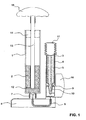
- FIG. 1 a first embodiment of a mixing device for mixing at least two components according to the present invention is shown.
- the mixing device has a mixing chamber 1 with a first component 2 and a component chamber 3, in which a component container 4 is accommodated with a second component 5.
- the mixing chamber 1 and the component chamber 3 are mounted on a base unit 6.
- the mixing chamber 1 is detachably attached to the base unit 6 by means of a screw connection 7, in this case a bayonet closure.
- the component chamber 3 is firmly connected in the embodiment shown with the base unit and in the present case formed integrally with the base unit. Alternatively, however, it is also possible to detachably connect the component chamber to the base unit.
- the component chamber 3 is connected to the mixing chamber 1 via a feed line 8.
- the supply line 8 passes through the base part 6 and opens at the top of the base unit of the base unit.
- the supply line extends into the screw connection 7 and, with the mixing chamber 1 in the mounted state of the mixing chamber, establishes a fluid connection to the interior of the mixing chamber.
- the feed line 8 opens into the interior of the component chamber 3.
- a filter may be provided, which can retain the first component 2, such as a powder in the mixing chamber.
- a further filter can be provided, the impurities or splinters, which arise for example by opening a component container in the form of an ampoule, can withhold.
- the mixing device is shown in a home position in which the components are stored separately in their respective chambers.
- the mixing chamber in the upper part of a connecting piece (not shown) for a vacuum device, which can generate a negative pressure in the mixing chamber relative to the component chamber.
- the component container 4 is held in the form of an ampoule by flexible lips 9 provided on an inwardly projecting flange of the component chamber.
- the flexible lips 9 project in a lower region near the outlet of the component chamber 3 to the feed line 8 into the interior of the component chamber 3.
- the component container 4 has at one end a container head 10, with which it protrudes through the flexible lips 9 of the component chamber and is held by this.
- the flexible lips 9 may be formed, for example, of elastic material, such as rubber, which abuts the container head 10 around its entire circumference and thus carries the component container 4 in the component chamber 3.
- the mixing device In the starting position according to FIG. 1 the mixing device is in a rest position, in which it can be stored for a long period of time.
- the flexible lips 9 act as sealing lips and form a kind of closure device between the mixing chamber and the component chamber.
- the flexible lips 9 divide the component chamber into two areas, one area in front of the closure device and one area behind the closure device in which the ampoule body is located. In the starting position according to FIG. 1
- the flexible lips 9 may be tight against the container head 10 so that the closure means is in a locked position.
- a display device in the form of an elastically deformable bellows 11 is provided, which can indicate a pressure change in the component chamber 3.
- the bellows 11 is located at an open end of the cylinder of the component chamber 3, which is opposite to the end, which faces the feed line 8.
- the bellows 11 is slipped with an opening over the opening of the component chamber 3 and closes the opening of the component chamber tightly.
- the bellows 11 is accordion-like, ie it has on its outer peripheral surface a zigzag-like, predetermined folding, along which the bellows can be compressed in the longitudinal direction, wherein the folds come to rest on each other. In the in FIG. 1 shown position, the bellows in a relaxed position, ie in the starting position.
- a relative to the mixing chamber movable mixer 12 is provided in the mixing chamber 1.
- the mixer 12 is mounted on a piston rod 13, which protrudes from the mixing chamber 1 at the end of the mixing chamber 1, which is opposite to the end in the direction of the feed line 8.
- the piston rod 13 is movably mounted in a plug 14, which closes the mixing chamber at this end tight.
- the piston rod 13 can be gripped by a handle 15 and the mixer 12 can be moved into and out of the mixing chamber 1 by pushing in and out and rotating the piston rod 13 in order to move the components together Mix.
- the mixing is preferably carried out in the mounted state of the mixing chamber 1 on the base unit 6.
- the mixing chamber 1 can also be removed before mixing of the base unit 6, wherein the opening 7 must be closed again for mixing.
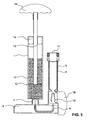
- FIG. 2 is the mixing device after FIG. 1 shown in a state in which the component container 4 has been opened.
- a rotary lever 16 is arranged, which is connected to an opening device in the interior of the component chamber 3 such that by turning the rotary lever 16 of the container head 10 is separated from the component container 4.
- the rotary lever 16 is shown in a downwardly rotated position in which the container head 10 has been separated, so that the second component 5 exits from the component container 4.
- the configuration of the opening device for the component container 4 is on the description of the already mentioned WO 2010/012114 A1 directed.
- the rotary lever 16 is to ensure that the transition to the component chamber 3 is sealed.
- the vacuum device can be activated, whereby a negative pressure is generated in the mixing chamber 1 relative to the Kompönentenhunt 3.
- a pressure equalization between the Kompönentenhunt 3 with higher pressure and the mixing chamber 1 at a lower pressure, so that in the component chamber 3, a pressure change, respectively, a reduction in pressure takes place.
- the rest of the second component 5 is conveyed through the supply line 8 into the mixing chamber 1.
- the second component also flows from the interior of the component container 4 and from the container head 10, which is held with the opening down from the opening device is, through the supply line 8 in the mixing chamber. 1
- the second component 5 has been completely transferred from the component chamber 3 into the mixing chamber.
- the negative pressure applied by the negative pressure device to the mixing chamber 1 extends through the supply line 8 to the component chamber 3 and the bellows 11. Due to the elastic properties of the bellows 11 this is by the concern of the negative pressure in its interior, in comparison to the ambient pressure, compressed.
- the compression of the bellows serves as an indication of the pressure change in the component chamber 3.
- the compression of the bellows 11 reduces the total volume of the component chamber 3.
- the bellows may, for example, on the outside in the areas between the folds have a reddish color and on the outside at the tips of the folds and the top of the bellows have a greenish color.
- the red areas between the folds are visible so that the starting position is displayed.
- the red areas between the pleats are covered by the juxtaposition of the pleats, and only the greenish color provided at the tips of the pleats is visible, whereby the pressure change can be displayed.
- the mixture 17 of the components 2 and 5 in the mixing chamber 1 can be made by moving the mixer 12 by means of the handle 15.
- the mixing chamber 1 can now be removed from the base unit 6.
- a discharge nozzle can then be attached and the mixture 17 can be discharged from the mixing chamber 1 in a known manner.
- a negative pressure in the mixing chamber 1 can be applied by means of the vacuum device even before opening the component container 4.
- z. B. serve the flexible lips 9 as a closure device.
- a negative pressure in the mixing chamber 1 in the supply line 8 and in the region of the component chamber 3, which lies in front of the flexible lips 9, or the supply line facing, a negative pressure.
- a higher pressure usually the ambient pressure
- FIG. 2 the closure device is in an opened state because the seal between the flexible lips 9 and the container head 10 has been resolved by separating the container head 10 from the component container 4.
- FIG. 4 a second embodiment of a mixing device according to the present invention is shown. Identical components are provided with the same reference numerals.
- a balloon bellows 18 is placed as a display device on the opening of the component chamber 3, which is opposite to the opening for the supply line 8.
- the balloon bellows 18 has an opening, on the circumference of an outer sealing lip 19 and an inner sealing lip 20 is provided, between which the peripheral edge of the component chamber 3 comes to rest in the assembled state.
- the outer sealing lip 19 of the balloon bellows 18 adjoins the outside of the component chamber 3 and the inner sealing lip 20 on the inside of the component chamber 3.
- a similar attachment can also be provided for the bellows 11.
- the balloon bellows 18 is bell-shaped and is made of such elastic material that its peripheral wall can curve inwards into the interior of the balloon volume. In FIG. 4 However, the balloon bellows is shown in expanded condition.
- the mixing apparatus has been described with reference to the drawings of various embodiments, which differ substantially by different design of a display device for indicating a change in pressure in the component chamber.
- the principle of the inventive mixing device with a display device for a Pressure change in a component chamber but also include other modifications.
- a second component can be provided directly in the component chamber 3, wherein a valve in the supply line 8 can serve as a closure device, for example.
- the display device elsewhere on the component chamber 3, such as in an area of the peripheral wall of the component chamber.
- other opening mechanisms for opening a component container may be provided than those described in the above-mentioned WO 2010 / 012114A1 are described.
- the mixing chamber may be formed without additional mixing elements, so that mixing of the components z. B. can be done by shaking the mixing chamber.
- more than one component chamber can preferably be connected to the mixing chamber, each with a display device.
Landscapes
- Chemical & Material Sciences (AREA)
- Chemical Kinetics & Catalysis (AREA)
- Package Specialized In Special Use (AREA)
- Mixers With Rotating Receptacles And Mixers With Vibration Mechanisms (AREA)
- Dental Tools And Instruments Or Auxiliary Dental Instruments (AREA)
Claims (14)
- Dispositif mélangeur pour le mélange d'au moins deux composants, présentant :- une cellule de mélange (1) contenant un premier composant (2),- au moins une cellule à composant (3) contenant un second composant (5) et qui est reliée ou peut être reliée à la cellule de mélange (1) par une conduite d'alimentation (8),- un dispositif de dépression permettant de générer une dépression dans la cellule de mélange (1) afin de transporter ainsi le second composant de la cellule à composant (3) à travers la conduite d' alimentation (8) vers la cellule de mélange (1) et- un dispositif d'affichage (11 ; 18) qui est prévu au niveau de la cellule à composant (3) pour afficher un changement de pression dans la cellule à composant (3), le dispositif d'affichage (11 ; 18) étant constitué par une partie élastique de la cellule à composant (3) ,caractérisé en ce que la partie élastique est formée d'un soufflet qui se raccorde à l'orifice de la cellule à composant (3) et que le soufflet se présente sous forme d'un soufflet accordéon (1) ou d'un soufflet ballon (18).
- Dispositif mélangeur selon la revendication 1, caractérisé en ce que la cellule à composant (3) présente une première extrémité au niveau de laquelle la conduite d'alimentation (8) est disposée et que la cellule à composant (3) présente une seconde extrémité qui est opposée à la première extrémité et au niveau de laquelle le dispositif d'affichage (11 ; 18) est disposé.
- Dispositif mélangeur selon la revendication 2, caractérisé en ce que le composant (5) ou un réservoir à composant (4) s'appuie par le composant (5) dans la cellule à composant (3) entre la conduite d'alimentation (8) et le dispositif d'affichage (11 ; 18).
- Dispositif mélangeur selon une des revendications précédentes, caractérisé en ce que le dispositif d'affichage (11 ; 18) est disposé de manière amovible au niveau de la cellule à composant (3).
- Dispositif mélangeur selon une des revendications précédentes, caractérisé en ce que le dispositif d'affichage (11 ; 18) est mobile à l'inverse d'une force d'élasticité depuis une position initiale jusqu'à une position d'affichage en différant.
- Dispositif mélangeur selon la revendication 5, caractérisé en ce que le dispositif d'affichage (11 ; 18) comprend un marquage coloré pour différencier la position initiale de la position d'affichage par la couleur.
- Dispositif mélangeur selon une des revendications précédentes, caractérisé en ce qu'un système d'ouverture est prévu au niveau de la cellule à composant (3) pour ouvrir le réservoir à composant (4).
- Dispositif mélangeur selon une des revendications précédentes, caractérisé en ce qu'un système de fermeture (9) qui bloque la conduite d'alimentation (8) dans une position initiale du dispositif mélangeur est prévu.
- Dispositif mélangeur selon une des revendications précédentes, caractérisé en ce qu'est prévue une unité de base (6) dans laquelle est installée au moins une partie de la conduite d' alimentation et qui présente des raccordements permettant de raccorder l'au moins une cellule à composant (3) et la conduite d'alimentation à la conduite d'alimentation (8) ou la partie de la conduite d'alimentation (8).
Applications Claiming Priority (2)
| Application Number | Priority Date | Filing Date | Title |
|---|---|---|---|
| CH892009 | 2009-01-21 | ||
| PCT/CH2009/000384 WO2010083616A1 (fr) | 2009-01-21 | 2009-12-02 | Dispositif mélangeur avec indication de changement de pression |
Publications (2)
| Publication Number | Publication Date |
|---|---|
| EP2379211A1 EP2379211A1 (fr) | 2011-10-26 |
| EP2379211B1 true EP2379211B1 (fr) | 2013-02-13 |
Family
ID=40548512
Family Applications (1)
| Application Number | Title | Priority Date | Filing Date |
|---|---|---|---|
| EP20090760699 Active EP2379211B1 (fr) | 2009-01-21 | 2009-12-02 | Dispositif mélangeur avec indication de changement de pression |
Country Status (4)
| Country | Link |
|---|---|
| US (1) | US9308506B2 (fr) |
| EP (1) | EP2379211B1 (fr) |
| CN (1) | CN102292147B (fr) |
| WO (1) | WO2010083616A1 (fr) |
Families Citing this family (6)
| Publication number | Priority date | Publication date | Assignee | Title |
|---|---|---|---|---|
| US8662736B2 (en) * | 2010-07-29 | 2014-03-04 | Heraeus Medical Gmbh | Bone cement system |
| DE102015106899B3 (de) * | 2015-05-04 | 2016-07-14 | Heraeus Medical Gmbh | Vorrichtung zum Mischen und Lagern von Polymethylmethacrylat-Knochenzement |
| DE102015116797B4 (de) | 2015-10-02 | 2018-08-23 | Heraeus Medical Gmbh | Vorrichtung und Verfahren zum Lagern und Mischen eines Knochenzements |
| CN107376749B (zh) * | 2017-06-30 | 2019-06-28 | 中国人民解放军第三军医大学第一附属医院 | 试剂快速配制针筒 |
| CN109158024A (zh) * | 2018-09-12 | 2019-01-08 | 贵州省独山县川旺饲料有限公司 | 一种可精确配比的饲料加工用制备装置 |
| CN110064332A (zh) * | 2019-04-10 | 2019-07-30 | 汪淑荣 | 一种药学室配药装置 |
Family Cites Families (18)
| Publication number | Priority date | Publication date | Assignee | Title |
|---|---|---|---|---|
| US3877682A (en) * | 1974-03-08 | 1975-04-15 | Mosstype Corp | Automatic chemical measuring and mixing machine |
| US4376439A (en) * | 1979-04-28 | 1983-03-15 | Lauterjung F G | Suction bottle for medical purposes particularly for the connection of drainage tubes |
| SE450545B (sv) * | 1984-10-19 | 1987-07-06 | Mit Ab | Forfarande och anordning vid framstellning av bencement for fixering av proteser |
| US5279550A (en) * | 1991-12-19 | 1994-01-18 | Gish Biomedical, Inc. | Orthopedic autotransfusion system |
| SE9301599L (sv) * | 1993-05-10 | 1994-06-27 | Cemvac System Ab | Anordning för inmatning av bencementkomponenter i ett under undertryck stående blandningskärl |
| DE19532015A1 (de) * | 1995-08-31 | 1997-03-06 | Alfred Von Schuckmann | Vorrichtung zum Mischen und Ausbringen von Mehrkomponentenprodukten |
| US5788463A (en) * | 1995-12-22 | 1998-08-04 | Chan; Kwan-Ho | Manual vacuum producing system having pressure indicator |
| US5779356A (en) | 1996-02-21 | 1998-07-14 | Chan; Kwan-Ho | Apparatus and method for mixing first and second components of a bone cement in a vacuum |
| CN1163147A (zh) * | 1996-02-21 | 1997-10-29 | 陈君豪 | 混合骨粘固剂的系统和方法 |
| US6042262A (en) * | 1997-07-29 | 2000-03-28 | Stryker Technologies Corportion | Apparatus for storing, mixing, and dispensing two-component bone cement |
| US6120174A (en) * | 1999-01-14 | 2000-09-19 | Bristol-Myers Squibb | Apparatus and method for mixing and dispensing bone cement |
| US6116773A (en) * | 1999-01-22 | 2000-09-12 | Murray; William M. | Bone cement mixer and method |
| US6254268B1 (en) * | 1999-07-16 | 2001-07-03 | Depuy Orthopaedics, Inc. | Bone cement mixing apparatus |
| US6435705B1 (en) * | 1999-04-16 | 2002-08-20 | Depuy Orthopaedics, Inc. | Apparatus and method for delivering and mixing a liquid bone cement component with a powder bone cement component |
| DE20005333U1 (de) * | 2000-02-28 | 2001-07-12 | Coripharm Medizinprodukte GmbH & Co. KG., 64807 Dieburg | Aufbereitungs- und Applikationsvorrichtung für Implantatmaterialien |
| EP1656214B1 (fr) * | 2003-08-21 | 2010-02-24 | Medmix Systems AG | Dispositif et procede pour transferer, melanger et distribuer des composants |
| US8096449B2 (en) * | 2006-07-17 | 2012-01-17 | Medmix Systems Ag | Dispensing appliance for a multiple cartridge |
| CN102066236B (zh) | 2008-07-29 | 2012-05-30 | 药物混合系统股份公司 | 一种用于打开封闭的流体容器的装置 |
-
2009
- 2009-12-02 EP EP20090760699 patent/EP2379211B1/fr active Active
- 2009-12-02 US US13/145,053 patent/US9308506B2/en active Active
- 2009-12-02 CN CN200980155070.1A patent/CN102292147B/zh active Active
- 2009-12-02 WO PCT/CH2009/000384 patent/WO2010083616A1/fr active Application Filing
Also Published As
| Publication number | Publication date |
|---|---|
| US9308506B2 (en) | 2016-04-12 |
| CN102292147B (zh) | 2014-03-12 |
| US20110273954A1 (en) | 2011-11-10 |
| CN102292147A (zh) | 2011-12-21 |
| WO2010083616A1 (fr) | 2010-07-29 |
| EP2379211A1 (fr) | 2011-10-26 |
Similar Documents
| Publication | Publication Date | Title |
|---|---|---|
| EP2379211B1 (fr) | Dispositif mélangeur avec indication de changement de pression | |
| EP2723482B1 (fr) | Dispositif destiné à mélanger et appliquer un produit ayant peu de bulles | |
| EP0663348B1 (fr) | Dispositif pour le vidage d'un sac tubulaire | |
| DE102010019223B4 (de) | Kartuschensystem mit Druckgaspatrone | |
| EP2303758B1 (fr) | Dispositif pour ouvrir un récipient de fluide fermé | |
| DE102010019222B4 (de) | Austragsvorrichtung für Kartuschen | |
| EP1830965B1 (fr) | Dispositif permettant l'ecoulement dose d'un fluide | |
| EP3272301B1 (fr) | Applicateur de ciment osseux à l'aide d'une vanne trois voies, destiné à la décharge de pression | |
| WO2005018830A2 (fr) | Dispositif et procede de conservation, de melange et d'application de constituants | |
| EP3317003B1 (fr) | Soupape pour agent de revêtement | |
| EP2823881A1 (fr) | Dispositif et procédé de stockage et de mélange de ciment osseux | |
| EP3050634A1 (fr) | Système d'application de pâte destiné au mélange d'une pâte à partir de deux composants | |
| DE602004005613T2 (de) | Pumpe zur abgabe eines fluidprodukts | |
| DE1425510B2 (de) | Druckbehälter, insbesondere für die Zuführung von Schmiermittel | |
| EP3529171A1 (fr) | Applicateur à plusieurs composants | |
| EP1624808B1 (fr) | Dispositif de decharge pour deux composants avec cartouche de decharge et melangeur | |
| DE19632717A1 (de) | Pneumatische Kartuschenauspreßvorrichtung | |
| EP2214839B1 (fr) | Générateur de colle à chaud | |
| EP1029513B1 (fr) | Capsule de mélange et d'application | |
| EP2711091A1 (fr) | Dispositif d'extraction pour masses liquides | |
| WO2019012156A1 (fr) | Fermeture de récipient dotée d'une capsule standard | |
| DE102007021634B3 (de) | Vorrichtung zur Dosierung von Flüssigkeit aus einem Gebinde | |
| EP4385613A1 (fr) | Dispositif pour mélanger du ciment osseux | |
| DE202014003991U1 (de) | Druckluft getriebener Spender | |
| DE102009056270B4 (de) | Vorrichtung und Verfahren zum Kompaktieren von kleinen Mengen pulverförmigen Materials |
Legal Events
| Date | Code | Title | Description |
|---|---|---|---|
| PUAI | Public reference made under article 153(3) epc to a published international application that has entered the european phase |
Free format text: ORIGINAL CODE: 0009012 |
|
| 17P | Request for examination filed |
Effective date: 20110622 |
|
| AK | Designated contracting states |
Kind code of ref document: A1 Designated state(s): AT BE BG CH CY CZ DE DK EE ES FI FR GB GR HR HU IE IS IT LI LT LU LV MC MK MT NL NO PL PT RO SE SI SK SM TR |
|
| DAX | Request for extension of the european patent (deleted) | ||
| GRAP | Despatch of communication of intention to grant a patent |
Free format text: ORIGINAL CODE: EPIDOSNIGR1 |
|
| RIC1 | Information provided on ipc code assigned before grant |
Ipc: B01F 11/00 20060101AFI20120906BHEP Ipc: B01F 15/02 20060101ALI20120906BHEP Ipc: A61F 2/30 20060101ALN20120906BHEP Ipc: B01F 13/06 20060101ALI20120906BHEP Ipc: B01F 15/00 20060101ALI20120906BHEP Ipc: A61F 2/46 20060101ALN20120906BHEP Ipc: B01F 13/00 20060101ALI20120906BHEP |
|
| GRAS | Grant fee paid |
Free format text: ORIGINAL CODE: EPIDOSNIGR3 |
|
| GRAA | (expected) grant |
Free format text: ORIGINAL CODE: 0009210 |
|
| AK | Designated contracting states |
Kind code of ref document: B1 Designated state(s): AT BE BG CH CY CZ DE DK EE ES FI FR GB GR HR HU IE IS IT LI LT LU LV MC MK MT NL NO PL PT RO SE SI SK SM TR |
|
| REG | Reference to a national code |
Ref country code: GB Ref legal event code: FG4D Free format text: NOT ENGLISH |
|
| REG | Reference to a national code |
Ref country code: AT Ref legal event code: REF Ref document number: 596162 Country of ref document: AT Kind code of ref document: T Effective date: 20130215 |
|
| REG | Reference to a national code |
Ref country code: IE Ref legal event code: FG4D Free format text: LANGUAGE OF EP DOCUMENT: GERMAN |
|
| REG | Reference to a national code |
Ref country code: CH Ref legal event code: NV Representative=s name: ISLER AND PEDRAZZINI AG, CH |
|
| REG | Reference to a national code |
Ref country code: DE Ref legal event code: R096 Ref document number: 502009006230 Country of ref document: DE Effective date: 20130411 |
|
| REG | Reference to a national code |
Ref country code: NL Ref legal event code: VDEP Effective date: 20130213 |
|
| REG | Reference to a national code |
Ref country code: LT Ref legal event code: MG4D |
|
| PG25 | Lapsed in a contracting state [announced via postgrant information from national office to epo] |
Ref country code: BG Free format text: LAPSE BECAUSE OF FAILURE TO SUBMIT A TRANSLATION OF THE DESCRIPTION OR TO PAY THE FEE WITHIN THE PRESCRIBED TIME-LIMIT Effective date: 20130513 Ref country code: IS Free format text: LAPSE BECAUSE OF FAILURE TO SUBMIT A TRANSLATION OF THE DESCRIPTION OR TO PAY THE FEE WITHIN THE PRESCRIBED TIME-LIMIT Effective date: 20130613 Ref country code: LT Free format text: LAPSE BECAUSE OF FAILURE TO SUBMIT A TRANSLATION OF THE DESCRIPTION OR TO PAY THE FEE WITHIN THE PRESCRIBED TIME-LIMIT Effective date: 20130213 Ref country code: NO Free format text: LAPSE BECAUSE OF FAILURE TO SUBMIT A TRANSLATION OF THE DESCRIPTION OR TO PAY THE FEE WITHIN THE PRESCRIBED TIME-LIMIT Effective date: 20130513 Ref country code: SE Free format text: LAPSE BECAUSE OF FAILURE TO SUBMIT A TRANSLATION OF THE DESCRIPTION OR TO PAY THE FEE WITHIN THE PRESCRIBED TIME-LIMIT Effective date: 20130213 Ref country code: ES Free format text: LAPSE BECAUSE OF FAILURE TO SUBMIT A TRANSLATION OF THE DESCRIPTION OR TO PAY THE FEE WITHIN THE PRESCRIBED TIME-LIMIT Effective date: 20130524 |
|
| PG25 | Lapsed in a contracting state [announced via postgrant information from national office to epo] |
Ref country code: FI Free format text: LAPSE BECAUSE OF FAILURE TO SUBMIT A TRANSLATION OF THE DESCRIPTION OR TO PAY THE FEE WITHIN THE PRESCRIBED TIME-LIMIT Effective date: 20130213 Ref country code: PL Free format text: LAPSE BECAUSE OF FAILURE TO SUBMIT A TRANSLATION OF THE DESCRIPTION OR TO PAY THE FEE WITHIN THE PRESCRIBED TIME-LIMIT Effective date: 20130213 Ref country code: SI Free format text: LAPSE BECAUSE OF FAILURE TO SUBMIT A TRANSLATION OF THE DESCRIPTION OR TO PAY THE FEE WITHIN THE PRESCRIBED TIME-LIMIT Effective date: 20130213 Ref country code: LV Free format text: LAPSE BECAUSE OF FAILURE TO SUBMIT A TRANSLATION OF THE DESCRIPTION OR TO PAY THE FEE WITHIN THE PRESCRIBED TIME-LIMIT Effective date: 20130213 Ref country code: PT Free format text: LAPSE BECAUSE OF FAILURE TO SUBMIT A TRANSLATION OF THE DESCRIPTION OR TO PAY THE FEE WITHIN THE PRESCRIBED TIME-LIMIT Effective date: 20130613 Ref country code: GR Free format text: LAPSE BECAUSE OF FAILURE TO SUBMIT A TRANSLATION OF THE DESCRIPTION OR TO PAY THE FEE WITHIN THE PRESCRIBED TIME-LIMIT Effective date: 20130514 |
|
| PG25 | Lapsed in a contracting state [announced via postgrant information from national office to epo] |
Ref country code: HR Free format text: LAPSE BECAUSE OF FAILURE TO SUBMIT A TRANSLATION OF THE DESCRIPTION OR TO PAY THE FEE WITHIN THE PRESCRIBED TIME-LIMIT Effective date: 20130213 |
|
| PG25 | Lapsed in a contracting state [announced via postgrant information from national office to epo] |
Ref country code: SK Free format text: LAPSE BECAUSE OF FAILURE TO SUBMIT A TRANSLATION OF THE DESCRIPTION OR TO PAY THE FEE WITHIN THE PRESCRIBED TIME-LIMIT Effective date: 20130213 Ref country code: CZ Free format text: LAPSE BECAUSE OF FAILURE TO SUBMIT A TRANSLATION OF THE DESCRIPTION OR TO PAY THE FEE WITHIN THE PRESCRIBED TIME-LIMIT Effective date: 20130213 Ref country code: RO Free format text: LAPSE BECAUSE OF FAILURE TO SUBMIT A TRANSLATION OF THE DESCRIPTION OR TO PAY THE FEE WITHIN THE PRESCRIBED TIME-LIMIT Effective date: 20130213 Ref country code: EE Free format text: LAPSE BECAUSE OF FAILURE TO SUBMIT A TRANSLATION OF THE DESCRIPTION OR TO PAY THE FEE WITHIN THE PRESCRIBED TIME-LIMIT Effective date: 20130213 Ref country code: NL Free format text: LAPSE BECAUSE OF FAILURE TO SUBMIT A TRANSLATION OF THE DESCRIPTION OR TO PAY THE FEE WITHIN THE PRESCRIBED TIME-LIMIT Effective date: 20130213 Ref country code: DK Free format text: LAPSE BECAUSE OF FAILURE TO SUBMIT A TRANSLATION OF THE DESCRIPTION OR TO PAY THE FEE WITHIN THE PRESCRIBED TIME-LIMIT Effective date: 20130213 |
|
| PLBE | No opposition filed within time limit |
Free format text: ORIGINAL CODE: 0009261 |
|
| STAA | Information on the status of an ep patent application or granted ep patent |
Free format text: STATUS: NO OPPOSITION FILED WITHIN TIME LIMIT |
|
| PG25 | Lapsed in a contracting state [announced via postgrant information from national office to epo] |
Ref country code: IT Free format text: LAPSE BECAUSE OF FAILURE TO SUBMIT A TRANSLATION OF THE DESCRIPTION OR TO PAY THE FEE WITHIN THE PRESCRIBED TIME-LIMIT Effective date: 20130213 |
|
| 26N | No opposition filed |
Effective date: 20131114 |
|
| REG | Reference to a national code |
Ref country code: DE Ref legal event code: R097 Ref document number: 502009006230 Country of ref document: DE Effective date: 20131114 |
|
| BERE | Be: lapsed |
Owner name: MEDMIX SYSTEMS A.G. Effective date: 20131231 |
|
| PG25 | Lapsed in a contracting state [announced via postgrant information from national office to epo] |
Ref country code: LU Free format text: LAPSE BECAUSE OF FAILURE TO SUBMIT A TRANSLATION OF THE DESCRIPTION OR TO PAY THE FEE WITHIN THE PRESCRIBED TIME-LIMIT Effective date: 20131202 |
|
| REG | Reference to a national code |
Ref country code: IE Ref legal event code: MM4A |
|
| PG25 | Lapsed in a contracting state [announced via postgrant information from national office to epo] |
Ref country code: IE Free format text: LAPSE BECAUSE OF NON-PAYMENT OF DUE FEES Effective date: 20131202 Ref country code: BE Free format text: LAPSE BECAUSE OF NON-PAYMENT OF DUE FEES Effective date: 20131231 |
|
| PG25 | Lapsed in a contracting state [announced via postgrant information from national office to epo] |
Ref country code: MC Free format text: LAPSE BECAUSE OF FAILURE TO SUBMIT A TRANSLATION OF THE DESCRIPTION OR TO PAY THE FEE WITHIN THE PRESCRIBED TIME-LIMIT Effective date: 20130213 |
|
| PG25 | Lapsed in a contracting state [announced via postgrant information from national office to epo] |
Ref country code: SM Free format text: LAPSE BECAUSE OF FAILURE TO SUBMIT A TRANSLATION OF THE DESCRIPTION OR TO PAY THE FEE WITHIN THE PRESCRIBED TIME-LIMIT Effective date: 20130213 |
|
| PG25 | Lapsed in a contracting state [announced via postgrant information from national office to epo] |
Ref country code: TR Free format text: LAPSE BECAUSE OF FAILURE TO SUBMIT A TRANSLATION OF THE DESCRIPTION OR TO PAY THE FEE WITHIN THE PRESCRIBED TIME-LIMIT Effective date: 20130213 Ref country code: CY Free format text: LAPSE BECAUSE OF FAILURE TO SUBMIT A TRANSLATION OF THE DESCRIPTION OR TO PAY THE FEE WITHIN THE PRESCRIBED TIME-LIMIT Effective date: 20130213 |
|
| REG | Reference to a national code |
Ref country code: DE Ref legal event code: R082 Ref document number: 502009006230 Country of ref document: DE Representative=s name: HOEGER, STELLRECHT & PARTNER PATENTANWAELTE MB, DE |
|
| PG25 | Lapsed in a contracting state [announced via postgrant information from national office to epo] |
Ref country code: MK Free format text: LAPSE BECAUSE OF FAILURE TO SUBMIT A TRANSLATION OF THE DESCRIPTION OR TO PAY THE FEE WITHIN THE PRESCRIBED TIME-LIMIT Effective date: 20130213 Ref country code: HU Free format text: LAPSE BECAUSE OF FAILURE TO SUBMIT A TRANSLATION OF THE DESCRIPTION OR TO PAY THE FEE WITHIN THE PRESCRIBED TIME-LIMIT; INVALID AB INITIO Effective date: 20091202 |
|
| PG25 | Lapsed in a contracting state [announced via postgrant information from national office to epo] |
Ref country code: MT Free format text: LAPSE BECAUSE OF FAILURE TO SUBMIT A TRANSLATION OF THE DESCRIPTION OR TO PAY THE FEE WITHIN THE PRESCRIBED TIME-LIMIT Effective date: 20130213 |
|
| REG | Reference to a national code |
Ref country code: FR Ref legal event code: PLFP Year of fee payment: 7 |
|
| REG | Reference to a national code |
Ref country code: AT Ref legal event code: MM01 Ref document number: 596162 Country of ref document: AT Kind code of ref document: T Effective date: 20141202 |
|
| PG25 | Lapsed in a contracting state [announced via postgrant information from national office to epo] |
Ref country code: AT Free format text: LAPSE BECAUSE OF NON-PAYMENT OF DUE FEES Effective date: 20141202 |
|
| REG | Reference to a national code |
Ref country code: FR Ref legal event code: PLFP Year of fee payment: 8 |
|
| REG | Reference to a national code |
Ref country code: FR Ref legal event code: PLFP Year of fee payment: 9 |
|
| REG | Reference to a national code |
Ref country code: CH Ref legal event code: PUE Owner name: SULZER MIXPAC AG, CH Free format text: FORMER OWNER: MEDMIX SYSTEMS AG, CH |
|
| REG | Reference to a national code |
Ref country code: DE Ref legal event code: R081 Ref document number: 502009006230 Country of ref document: DE Owner name: MEDMIX SWITZERLAND AG, CH Free format text: FORMER OWNER: MEDMIX SYSTEMS AG, ROTKREUZ, CH Ref country code: DE Ref legal event code: R082 Ref document number: 502009006230 Country of ref document: DE Representative=s name: HOEGER, STELLRECHT & PARTNER PATENTANWAELTE MB, DE Ref country code: DE Ref legal event code: R081 Ref document number: 502009006230 Country of ref document: DE Owner name: SULZER MIXPAC AG, CH Free format text: FORMER OWNER: MEDMIX SYSTEMS AG, ROTKREUZ, CH Ref country code: DE Ref legal event code: R082 Ref document number: 502009006230 Country of ref document: DE Representative=s name: MANITZ FINSTERWALD PATENT- UND RECHTSANWALTSPA, DE |
|
| REG | Reference to a national code |
Ref country code: DE Ref legal event code: R082 Ref document number: 502009006230 Country of ref document: DE Representative=s name: HOEGER, STELLRECHT & PARTNER PATENTANWAELTE MB, DE Ref country code: DE Ref legal event code: R082 Ref document number: 502009006230 Country of ref document: DE Representative=s name: MANITZ FINSTERWALD PATENT- UND RECHTSANWALTSPA, DE |
|
| REG | Reference to a national code |
Ref country code: GB Ref legal event code: 732E Free format text: REGISTERED BETWEEN 20190718 AND 20190724 |
|
| REG | Reference to a national code |
Ref country code: DE Ref legal event code: R082 Ref document number: 502009006230 Country of ref document: DE Representative=s name: MANITZ FINSTERWALD PATENT- UND RECHTSANWALTSPA, DE |
|
| REG | Reference to a national code |
Ref country code: DE Ref legal event code: R079 Ref document number: 502009006230 Country of ref document: DE Free format text: PREVIOUS MAIN CLASS: B01F0011000000 Ipc: B01F0031000000 |
|
| REG | Reference to a national code |
Ref country code: DE Ref legal event code: R081 Ref document number: 502009006230 Country of ref document: DE Owner name: MEDMIX SWITZERLAND AG, CH Free format text: FORMER OWNER: SULZER MIXPAC AG, HAAG, CH |
|
| P01 | Opt-out of the competence of the unified patent court (upc) registered |
Effective date: 20230505 |
|
| PGFP | Annual fee paid to national office [announced via postgrant information from national office to epo] |
Ref country code: GB Payment date: 20231220 Year of fee payment: 15 |
|
| PGFP | Annual fee paid to national office [announced via postgrant information from national office to epo] |
Ref country code: FR Payment date: 20231221 Year of fee payment: 15 Ref country code: DE Payment date: 20231214 Year of fee payment: 15 |
|
| PGFP | Annual fee paid to national office [announced via postgrant information from national office to epo] |
Ref country code: CH Payment date: 20240101 Year of fee payment: 15 |