EP2378309A1 - Capteur optoélectronique et procédé de production d'informations sur des objets dans une zone de surveillance - Google Patents
Capteur optoélectronique et procédé de production d'informations sur des objets dans une zone de surveillance Download PDFInfo
- Publication number
- EP2378309A1 EP2378309A1 EP10159752A EP10159752A EP2378309A1 EP 2378309 A1 EP2378309 A1 EP 2378309A1 EP 10159752 A EP10159752 A EP 10159752A EP 10159752 A EP10159752 A EP 10159752A EP 2378309 A1 EP2378309 A1 EP 2378309A1
- Authority
- EP
- European Patent Office
- Prior art keywords
- light
- sensor
- deflection unit
- light beam
- deflection
- Prior art date
- Legal status (The legal status is an assumption and is not a legal conclusion. Google has not performed a legal analysis and makes no representation as to the accuracy of the status listed.)
- Granted
Links
Images


Classifications
-
- G—PHYSICS
- G01—MEASURING; TESTING
- G01S—RADIO DIRECTION-FINDING; RADIO NAVIGATION; DETERMINING DISTANCE OR VELOCITY BY USE OF RADIO WAVES; LOCATING OR PRESENCE-DETECTING BY USE OF THE REFLECTION OR RERADIATION OF RADIO WAVES; ANALOGOUS ARRANGEMENTS USING OTHER WAVES
- G01S7/00—Details of systems according to groups G01S13/00, G01S15/00, G01S17/00
- G01S7/48—Details of systems according to groups G01S13/00, G01S15/00, G01S17/00 of systems according to group G01S17/00
- G01S7/481—Constructional features, e.g. arrangements of optical elements
- G01S7/4816—Constructional features, e.g. arrangements of optical elements of receivers alone
-
- G—PHYSICS
- G01—MEASURING; TESTING
- G01S—RADIO DIRECTION-FINDING; RADIO NAVIGATION; DETERMINING DISTANCE OR VELOCITY BY USE OF RADIO WAVES; LOCATING OR PRESENCE-DETECTING BY USE OF THE REFLECTION OR RERADIATION OF RADIO WAVES; ANALOGOUS ARRANGEMENTS USING OTHER WAVES
- G01S17/00—Systems using the reflection or reradiation of electromagnetic waves other than radio waves, e.g. lidar systems
- G01S17/02—Systems using the reflection of electromagnetic waves other than radio waves
- G01S17/06—Systems determining position data of a target
- G01S17/42—Simultaneous measurement of distance and other co-ordinates
-
- G—PHYSICS
- G01—MEASURING; TESTING
- G01S—RADIO DIRECTION-FINDING; RADIO NAVIGATION; DETERMINING DISTANCE OR VELOCITY BY USE OF RADIO WAVES; LOCATING OR PRESENCE-DETECTING BY USE OF THE REFLECTION OR RERADIATION OF RADIO WAVES; ANALOGOUS ARRANGEMENTS USING OTHER WAVES
- G01S7/00—Details of systems according to groups G01S13/00, G01S15/00, G01S17/00
- G01S7/48—Details of systems according to groups G01S13/00, G01S15/00, G01S17/00 of systems according to group G01S17/00
- G01S7/481—Constructional features, e.g. arrangements of optical elements
- G01S7/4817—Constructional features, e.g. arrangements of optical elements relating to scanning
-
- G—PHYSICS
- G02—OPTICS
- G02B—OPTICAL ELEMENTS, SYSTEMS OR APPARATUS
- G02B19/00—Condensers, e.g. light collectors or similar non-imaging optics
- G02B19/0004—Condensers, e.g. light collectors or similar non-imaging optics characterised by the optical means employed
- G02B19/0019—Condensers, e.g. light collectors or similar non-imaging optics characterised by the optical means employed having reflective surfaces only (e.g. louvre systems, systems with multiple planar reflectors)
- G02B19/0023—Condensers, e.g. light collectors or similar non-imaging optics characterised by the optical means employed having reflective surfaces only (e.g. louvre systems, systems with multiple planar reflectors) at least one surface having optical power
-
- G—PHYSICS
- G02—OPTICS
- G02B—OPTICAL ELEMENTS, SYSTEMS OR APPARATUS
- G02B19/00—Condensers, e.g. light collectors or similar non-imaging optics
- G02B19/0033—Condensers, e.g. light collectors or similar non-imaging optics characterised by the use
- G02B19/0085—Condensers, e.g. light collectors or similar non-imaging optics characterised by the use for use with both a detector and a source
-
- G—PHYSICS
- G02—OPTICS
- G02B—OPTICAL ELEMENTS, SYSTEMS OR APPARATUS
- G02B5/00—Optical elements other than lenses
- G02B5/08—Mirrors
- G02B5/10—Mirrors with curved faces
Definitions
- the invention relates to an optoelectronic sensor, in particular a laser scanner, and to a method for generating information about objects in a surveillance area according to the preamble of claims 1 and 15, respectively.
- Laser scanners are used in many applications for object detection.
- a light beam generated by a laser periodically sweeps a surveillance area by means of a deflection unit.
- the light is remitted to objects in the surveillance area and evaluated in the scanner. From the angular position of the deflection is on the angular position of the object and from the light transit time using the speed of light in addition to the removal of the object from the laser scanner closed.
- the location of an object in the surveillance area is recorded in two-dimensional polar coordinates.
- the third spatial coordinate can also be detected by a relative movement in the transverse direction, for example by a further degree of freedom of movement of the deflection unit in the laser scanner or by the object being conveyed relative to the laser scanner.
- a relative movement in the transverse direction for example by a further degree of freedom of movement of the deflection unit in the laser scanner or by the object being conveyed relative to the laser scanner.
- laser scanners are also used in security technology for monitoring a source of danger such as a dangerous one Machine represents.
- a safety laser scanner is from the DE 43 40 756 A1 known.
- a protective field is monitored, which must not be entered by the operating personnel during operation of the machine. If the laser scanner detects an inadmissible protective field intervention, for example a leg of an operator, it triggers an emergency stop of the machine. Other interference with the protective field, for example due to static machine parts, can be taught in advance as permissible.
- the protective fields are preceded by warning fields, where interventions initially only lead to a warning in order to prevent the interception of the protective field and thus the protection in good time, thus increasing the availability of the system.
- Safety laser scanners usually work pulse-based.
- Sensors used in safety technology must work extremely reliably and therefore meet high safety requirements, for example the EN13849 standard for machine safety and the EN61496 device standard for non-contact protective devices (ESPE).
- ESE non-contact protective devices
- a number of measures must be taken, such as safe electronic evaluation by redundant, diverse electronics, function monitoring or specially monitoring the contamination of optical components, in particular a windscreen, and / or providing individual test objectives with defined degrees of reflection, among the corresponding scan angles must be detected.
- the optical system consists of an autocollimation arrangement of the transmitting unit and the receiving optics with associated receiving element.
- the receiving optics usually comprises a simple converging lens.
- a disadvantage of the arrangement with such a converging lens is the effect of the so-called Kernabschattung.
- a deflection unit for the coupling of the transmission beam shadows the central portion of the reception light, so that this proportion can not be registered on the reception element.
- the DE 10 2006 040 812 A1 uses an off-axis parabolic mirror instead of a flat rotating mirror and a receiving lens.
- a similar concept is also in the US2009 / 0122294 A1 or the JP3175390A described.
- the conventional parabolic mirrors are highly sensitive to tilting because of the high numerical aperture and therefore have to be very elaborately and precisely adjusted in production.
- the problem of kernel shading has a particularly strong effect if the laser scanner is to be further miniaturized.
- an optoelectronic sensor according to claim 1 and a method for generating information about objects in a surveillance area according to claim 15.
- the invention is based on the basic idea of integrating the optical properties of the transmission optics into the deflection unit.
- the deflection unit is concave in order to focus the received light simultaneously with the deflection on the light receiver. So that the shading or other losses by the coupling of the emitted light beam prevents the detection of objects at certain distances, in particular by Kernabschattung in the vicinity, are provided on the deflection unit zones with different imaging properties. With more than one other zones, finer gradations can be achieved, in which case the other zones each have a different focal length than the main zone and at the same time preferably also have a different focal length from each other.
- the invention has the advantage that with the deflection unit according to the invention very high numerical apertures can be generated and thus the deflection with the receiving side image is combined. This dispenses with the need for a separate optical receiver and thus also saves the space for the light path between the receiving optics and the light receiver. This allows a particularly small size of the Sensor.
- the sensor is inexpensive, because the three elements mirror carrier, mirror and receiving optics or generally carrier of the deflection, deflection and receiving side image are integrated in one component.
- the received signal waveform is insensitive to production-related deviations from the transmitting and receiving axis. Because of the high robustness against tilting of the entire deflection unit, the production and assembly is facilitated.
- the deflection unit is preferably movable, in particular a rotating mirror.
- the optics principle according to the invention can also be used with a static sensor, such as a light scanner.
- a static sensor such as a light scanner.
- a laser scanner is produced, in which the deflection unit periodically deflects the emitted light beam into a monitoring plane and thus periodically scans this scan plane.
- the deflection unit is preferably integrally formed with the main zone and the other zones. This leads to a particularly cost-effective deflection unit, in which no further adjustments must be made.
- a one-piece deflection unit can be produced, for example, as an injection-molded part. In this case, a reflective coating is preferably applied.
- the main zone is preferably as a remote zone and the other zones are preferably designed as near zones.
- the received signal thus remains stable over a particularly wide range of different object distances.
- the core shading can be compensated by the near zones.
- the main zone is preferably formed optically imaging with a first focal length.
- the main zone should direct as much light as possible to the light receiver. Since its extent is usually very small, this is best achieved by mapping the receiving spot onto the light receiver.
- the further zones can likewise be formed optically imaging, wherein they then have a second focal length different from the first focal length. Also with each other, the focal lengths of the other zones, if more of the other zones are present, still vary, so be provided a third and additional focal lengths.
- the other zones are formed with optically non-imaging, in particular light-scattering or redistributing light properties, for example to produce a homogeneous light distribution on the light receiver.
- the other zones can also be flat and only scatter the light.
- the deflection unit has a remote zone and two near zones.
- the deflection unit has a remote zone and two near zones.
- the further zones are preferably formed as annular segments in the main zone. This preserves an association between the zones and a specific range of object distances.
- Each annular segment is mainly responsible for a specific object distance range and optimized in its shape for it.
- the other zones are preferably tilted with respect to the main zone and with each other by a tilt angle. This reduces the adjustment requirements in production and assembly. Figuratively speaking, at least one of the tilted zones always begins to receive enough light in a slightly misaligned arrangement.
- the tilt angle is more preferably less than 1 ° ° even or less than 0.5 °. This is a balance between precise optical properties and not too high demands on the adjustment found.
- the deflection unit preferably has a flat segment for deflecting the emitted light beam.
- the deflection unit is thus responsible not only for the received light, but also for the emitted light beam. With a laser scanner, the same rotary motion is thus used for the transmission path and the reception path.
- the flat segment is arranged in particular in the center of the main zone, so that the emitted light beam is deflected centrally and independently of the angular position of the deflection into the surveillance area.
- the main zone and / or the further zones have essentially the shape of a paraboloid, a hyperboloid or an ellipsoid.
- These contours are particularly suitable for reception-side imaging.
- the shape only has to substantially correspond to the aforementioned contour, so that, for example, in the case of a paraboloid, small correction terms higher than second order are permitted or vice versa the development of a hyperboloid or an ellipsoid at higher orders is interrupted without any particular influence on the optical properties of the contour.
- an off-axis arrangement is provided. This means that selectively no symmetrical portion of the contour is selected around the vertex or the puncture point of a main axis.
- the monitoring area is preferably a scanning plane, which can be scanned by the light beam by means of the deflection unit. More preferably, the optical axis of the light receiver and the scanning plane are perpendicular to each other.
- the optical axis of the light emitter is preferably at an acute angle to the optical axis of the light receiver, wherein a deflection mirror or a beam splitter is provided which is oriented at half the acute angle and is arranged between the light receiver and deflection unit, in particular above the center of the main zone.
- a deflection mirror or a beam splitter is provided which is oriented at half the acute angle and is arranged between the light receiver and deflection unit, in particular above the center of the main zone.
- a hollow shaft drive is provided for the deflection unit, and the light emitter is arranged in a plane below and the light receiver in a plane above the deflection unit, wherein in particular the optical axes of light emitter and light receiver are aligned in a common axis to each other.
- the drive requires a little more space, but the transmitter can be accommodated extremely compact.
- the deflection unit has particularly preferably in the extension of the hollow shaft to an opening, wherein in the opening a flat mirror segment for 90 'beam deflection of the emitted light beam is provided.
- This is the equivalent of a flat mirror segment in the arrangement of light emitter and light receiver on the same side of the deflection unit.
- the deflection for the emitted light beam is integrated in a simple, space-saving and cost-effective manner in the deflection.
- a protractor for determining a rotational position of the deflection unit, wherein the sensor is designed to be distance-measuring in that the distance to the objects can be determined in the evaluation unit from a light transit time of the emitted and again received light beam.
- the sensor measures the object positions and, if applicable, their contour in two-dimensional polar coordinates and thus captures all relevant position data of the objects in the monitoring area.
- the evaluation unit is preferably designed to detect interventions in a protective field within the monitoring area on the basis of the received signal and then to provide a safety signal.
- the sensor is designed as a safe sensor, in particular as a safety sensor in the sense of the aforementioned standards.
- the particularly small size makes it even easier to integrate the sensor into the systems and processes to be monitored.
- Fig. 1 shows a schematic sectional view through a sensor according to the invention 10.
- the invention will be described with reference to a safety laser scanner, but the principle is also applicable to other groping optoelectronic sensors and for applications outside the safety technology.
- a light transmitter 12 for example with a laser light source, generates a transmitted light beam 16 with individual short light pulses with the aid of transmission optics 14.
- the sensor 10 operates instead of a pulse method with the phase method described in the introduction.
- the transmitted light beam 16 is emitted by means of a deflecting mirror 18 and a deflection unit 20 in a monitoring area 22.
- a polarization splitter can also be used.
- the deflection unit 20 is concavely curved, ie a concave mirror, for example in the form of an off-axis paraboloid. In this case, the transmitted light beam strikes a plane or flat sub-segment 24 of the deflection unit 20.
- the exact configuration of the deflection unit 20 will be described below with reference to FIGS FIGS. 2 to 5 explained in more detail.
- the transmitted light beam 16 is remitted in the monitoring area 22 of any existing objects and then, depending on the optical properties of the object surface attenuated and / or scattered, at least partially as a remitted light beam 26 to the sensor 10 back.
- a light receiver 28 for example, a photodiode.
- An additional, not shown, receiving optics may be provided in front of the light receiver 28 in order to achieve desired optical properties together with the beam shaping properties of the deflection unit 20.
- the light emitter 12 is inclined in this embodiment, so its optical axis includes with the optical axis of the light receiver 28 an acute angle.
- the deflection unit 18 is therefore obliquely aligned with the half acute angle that the transmitting beam 16 is deflected parallel to the optical axis of the light receiver 28 to the sub-segment 24.
- the sub-segment 24 provides in turn for a vertical light deflection to evenly scan a plane as a monitoring area 22.
- the deflection unit 20 is designed as a rotating mirror, which rotates continuously by driving a motor 30.
- the respective angular position of the deflection unit 20 is detected by an encoder 32.
- the transmitted light beam 16 generated by the light emitter 12 thus passes over the monitoring area 22 generated by the rotational movement. If a remitted light beam 24 received by the light receiver 28 is received from the surveillance area 22, the angle position of the deflection unit 20 can be adjusted to the angular position of the deflection unit 20 by means of the encoder 32 Object in the monitoring area 22 are closed.
- the transit time of the individual laser light pulses from their emission to the reception after reflection on the object in the monitoring region 22 is determined. From the light transit time, the distance of the object from the sensor 10 is closed using the speed of light. This evaluation takes place in an evaluation unit 34 which is connected to the light transmitter 12, the light receiver 26, the motor 30 and the encoder 32. Thus, two-dimensional polar coordinates of all objects in the monitoring area 22 are available via the angle and the distance.
- the aim of the evaluation is to provide a safety signal at a safety output 36 (OSSD, output signal switching device), for example, to trigger an emergency stop of a connected machine.
- the evaluation unit 34 uses the angle and distance data to calculate the location of an object in the monitoring area 22. This is compared with a two-dimensional protective field whose geometry is stored by appropriate parameters in a memory 38 of the evaluation unit 34. Thus, the evaluation unit 34 detects whether the protective field is injured, that is, if an inadmissible object is located in it and switches the safety output 36 depending on the result.
- the evaluation or parts of the evaluation take place in an internal evaluation unit 34 in a higher-level evaluation unit To make control.
- All said functional components are arranged in a housing 40 which has a front screen 42 on the front side, that is to say in the region of the light exit and light entry.
- the front screen 42 is placed obliquely to avoid direct reflections in the light receiver 28, so that transmit light beam 16 and windshield 42 include an angle not equal to ninety degrees.
- a scan plane can be monitored in a viewing angle of up to 270 °.
- a reference target may be provided to test the function of the light emitter 12. This is an exemplary way to meet one of the requirements of the aforementioned safety standards, with which the sensor 10 becomes a safe sensor.
- the optical system shown also allows a larger viewing angle of up to 360 °.
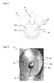
- FIG. 2 shows the deflection unit 20 and the deflection mirror arranged above 18 in a three-dimensional view.
- FIG. 3 is a section through this illustration, FIG. 4 a top view and FIG. 5 a photo of an embodiment of the deflection unit 20 as directly connected to the motor 30, one-piece injection-molded part with a mirror surface.
- the deflection unit 20 is designed overall as a concave, rotationally symmetrical mirror and is an off-axis paraboloid in the illustration. However, according to the invention, it is not important for a curvature exactly in the form of a paraboloid, as long as the deflection unit 20 fulfills the task of beam shaping, in that the remitted light beam 26 is deflected in a focused manner onto the light receiver 28. There are correction terms higher than second order possible.
- the shaping can also be derived from an ellipsoid or a hyperboloid, wherein then preferably an approximation is broken off at a certain order.
- the deflection unit 20 has, on the one hand, the central, plane sub-segment 24 for the transmitted light beam 16. As can be seen from the illustration, the deflecting mirror 18 shadows a portion of the remitted light beam 26, so that this portion does not reach the light receiver 28. This Kernabschattung leads to a significant loss of intensity, especially in the vicinity.
- additional near zones 46a-b are provided. Shown are two such near zones 46a-b, which is a good Compromise between sufficient adjustment options for the optimization of the reception intensity, sufficient light incidence per near zone 46a-b and manageability of the design and manufacture of the deflection unit 20 forms. But there are alternatively other Nahzonen or an embodiment with only one Nahzone conceivable.
- the near zones 46a-b are arranged in the illustration as concentric rings around the central sub-segment 24. It means centrally that the sub-segment 24 is symmetrical to the axis of rotation of the deflection unit 20. However, sub-segment 24 and near zones 46a-b are generally eccentric on deflection unit 20, i. the main zone 44 occupies more area up toward the light receiver than to the monitoring area 22.
- the near zones 46a-b are curved in the same way as the main zone 44, that is to say configured as paraboloid segments, for example. In this case, however, the near zones 46a-b have a different curvature from each other and to the main zone and a different off-axis offset. The result is a multizone receiving paraboloid as a deflection unit 20.
- the near zones 46a-b are also tilted toward each other and to the main zone 44, preferably at a small angle of less than 1 ° or even less than 0.5 °. This tilting causes at least some of the zones 44, 46a-b remain aligned properly with smaller misalignment of the deflection unit 20. This creates a certain insensitivity to tilting of the entire deflection unit 20.
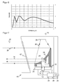
- FIG. 6 shows an exemplary intensity profile over the distance.
- two initial maxima can be identified, which are assigned to the near zones 46a-b, and a substantially flatter maximum of the main zone 44.
- the intensity portion of the main zone 44 dominates the long range. Without the near zones 46-b, practically no signal would be received for distances below half a meter due to the core shading.
- the near zones 46a-b contribute to longer distances of about one meter, and moreover, hardly any. In the overlay stands for all distances a sufficient received signal available. By further Nahzonen 46a-b could, if necessary, the intensity curve be smoothed even more by the intermediate minima are mitigated.
- FIG. 7 shows a schematic sectional view of a further embodiment of a sensor 10 according to the invention.
- the motor 30 is designed as a hollow shaft motor.
- the light emitter 12 is located opposite the light receiver 28, with mutual common optical axis, below the motor 30 so that the transmitted light beam 16 passes through the quill.
- the deflection unit 20 has in the extension of the hollow shaft to an opening in which the planar sub-segment 24 is oriented so that the transmitted light beam 16 is deflected at right angles in the monitoring area 22. On a deflecting mirror 18 can be omitted. Although there is no kernel shadowing in the true sense of the word, but a very similar effect by the amount of light that can not get to the light receiver 28 because of the subsegment 24.
- the deflection unit 20 likewise has at least one near zone and, apart from the opening and the changed arrangement of the subsegment 24, features analogously to the deflection unit 20 described and illustrated above.
Landscapes
- Physics & Mathematics (AREA)
- Engineering & Computer Science (AREA)
- General Physics & Mathematics (AREA)
- Computer Networks & Wireless Communication (AREA)
- Radar, Positioning & Navigation (AREA)
- Remote Sensing (AREA)
- Optics & Photonics (AREA)
- Electromagnetism (AREA)
- Optical Radar Systems And Details Thereof (AREA)
- Measurement Of Optical Distance (AREA)
Priority Applications (1)
| Application Number | Priority Date | Filing Date | Title |
|---|---|---|---|
| EP10159752.4A EP2378309B2 (fr) | 2010-04-13 | 2010-04-13 | Capteur optoélectronique et procédé de production d'informations sur des objets dans une zone de surveillance |
Applications Claiming Priority (1)
| Application Number | Priority Date | Filing Date | Title |
|---|---|---|---|
| EP10159752.4A EP2378309B2 (fr) | 2010-04-13 | 2010-04-13 | Capteur optoélectronique et procédé de production d'informations sur des objets dans une zone de surveillance |
Publications (3)
| Publication Number | Publication Date |
|---|---|
| EP2378309A1 true EP2378309A1 (fr) | 2011-10-19 |
| EP2378309B1 EP2378309B1 (fr) | 2012-07-04 |
| EP2378309B2 EP2378309B2 (fr) | 2023-08-09 |
Family
ID=42735334
Family Applications (1)
| Application Number | Title | Priority Date | Filing Date |
|---|---|---|---|
| EP10159752.4A Active EP2378309B2 (fr) | 2010-04-13 | 2010-04-13 | Capteur optoélectronique et procédé de production d'informations sur des objets dans une zone de surveillance |
Country Status (1)
| Country | Link |
|---|---|
| EP (1) | EP2378309B2 (fr) |
Cited By (9)
| Publication number | Priority date | Publication date | Assignee | Title |
|---|---|---|---|---|
| DE102012107794A1 (de) * | 2012-08-23 | 2014-02-27 | Osram Opto Semiconductors Gmbh | Optoelektronische Vorrichtung |
| US8681319B2 (en) | 2011-03-31 | 2014-03-25 | Denso Wave Incorporated | Laser radar for three-dimensional scanning |
| DE202013103233U1 (de) | 2013-07-18 | 2014-10-20 | Sick Ag | Optoelektronischer Sensor zur Erfassung von Objekten |
| EP2827173A2 (fr) | 2013-07-18 | 2015-01-21 | Sick Ag | Capteur optoélectronique et procédé destiné à la détection d'objets |
| EP2860546A1 (fr) * | 2013-10-09 | 2015-04-15 | Hexagon Technology Center GmbH | Appareil de mesure doté d'un miroir rotatif pour le balayage optique d'un environnement |
| WO2020088995A1 (fr) * | 2018-10-31 | 2020-05-07 | Osram Gmbh | Unité de mesure de distance |
| EP3671264A1 (fr) | 2018-12-21 | 2020-06-24 | Sick Ag | Capteur et procédé de détection d'un objet |
| CN111610532A (zh) * | 2019-02-22 | 2020-09-01 | 西克股份公司 | 光电传感器和用于检测对象的方法 |
| WO2020182782A1 (fr) * | 2019-03-12 | 2020-09-17 | Valeo Schalter Und Sensoren Gmbh | Dispositif de déviation de signal lumineux pour un système de mesure optique destiné à détecter des objets, système de mesure et procédé permettant de faire fonctionner un dispositif de déviation de signal lumineux |
Families Citing this family (5)
| Publication number | Priority date | Publication date | Assignee | Title |
|---|---|---|---|---|
| EP2759845B1 (fr) | 2013-01-28 | 2015-09-16 | Sick Ag | Capteur optoélectronique |
| US9964437B2 (en) | 2016-05-03 | 2018-05-08 | Datalogic IP Tech, S.r.l. | Laser scanner with reduced internal optical reflection comprising a light detector disposed between an interference filter and a collecting mirror |
| US10048120B2 (en) | 2016-05-03 | 2018-08-14 | Datalogic IP Tech, S.r.l. | Laser scanner and optical system |
| US11585905B2 (en) | 2016-05-03 | 2023-02-21 | Datalogic Ip Tech S.R.L. | Laser scanner |
| US10061021B2 (en) | 2016-07-06 | 2018-08-28 | Datalogic IP Tech, S.r.l. | Clutter filter configuration for safety laser scanner |
Citations (6)
| Publication number | Priority date | Publication date | Assignee | Title |
|---|---|---|---|---|
| JPH03175390A (ja) | 1989-12-04 | 1991-07-30 | Nippondenso Co Ltd | レーザレーダ走査装置 |
| DE4340756A1 (de) | 1992-12-08 | 1994-06-09 | Sick Optik Elektronik Erwin | Laserabstandsermittlungsvorrichtung |
| EP0897120A2 (fr) * | 1997-08-13 | 1999-02-17 | Schmersal-EOT GmbH & Co. KG | Dispositif pour localiser l'entrée d'objets dans un domaine spatial surveillé |
| DE102006040812A1 (de) | 2005-08-31 | 2007-05-24 | Zoller & Fröhlich GmbH | Empfangsvorrichtung für Laserscanner |
| US20090122294A1 (en) | 2007-11-12 | 2009-05-14 | Denso Wave Incorporated | Laser radar apparatus that measures direction and distance of an object |
| EP2101189A1 (fr) * | 2008-03-14 | 2009-09-16 | Firma Pepperl + Fuchs GmbH | Capteur optique |
-
2010
- 2010-04-13 EP EP10159752.4A patent/EP2378309B2/fr active Active
Patent Citations (7)
| Publication number | Priority date | Publication date | Assignee | Title |
|---|---|---|---|---|
| JPH03175390A (ja) | 1989-12-04 | 1991-07-30 | Nippondenso Co Ltd | レーザレーダ走査装置 |
| DE4340756A1 (de) | 1992-12-08 | 1994-06-09 | Sick Optik Elektronik Erwin | Laserabstandsermittlungsvorrichtung |
| EP0897120A2 (fr) * | 1997-08-13 | 1999-02-17 | Schmersal-EOT GmbH & Co. KG | Dispositif pour localiser l'entrée d'objets dans un domaine spatial surveillé |
| EP0897120B1 (fr) | 1997-08-13 | 2003-10-01 | Schmersal-EOT GmbH & Co. KG | Dispositif pour localiser l'entrée d'objets dans un domaine spatial surveillé |
| DE102006040812A1 (de) | 2005-08-31 | 2007-05-24 | Zoller & Fröhlich GmbH | Empfangsvorrichtung für Laserscanner |
| US20090122294A1 (en) | 2007-11-12 | 2009-05-14 | Denso Wave Incorporated | Laser radar apparatus that measures direction and distance of an object |
| EP2101189A1 (fr) * | 2008-03-14 | 2009-09-16 | Firma Pepperl + Fuchs GmbH | Capteur optique |
Cited By (18)
| Publication number | Priority date | Publication date | Assignee | Title |
|---|---|---|---|---|
| US8681319B2 (en) | 2011-03-31 | 2014-03-25 | Denso Wave Incorporated | Laser radar for three-dimensional scanning |
| DE102012102244B4 (de) * | 2011-03-31 | 2015-02-12 | Denso Wave Inc. | Laserradar für dreidimensionales Scannen |
| US9606231B2 (en) | 2012-08-23 | 2017-03-28 | Osram Opto Semiconductors Gmbh | Optoelectronic apparatus |
| DE102012107794B4 (de) | 2012-08-23 | 2023-10-19 | OSRAM Opto Semiconductors Gesellschaft mit beschränkter Haftung | Optoelektronische Vorrichtung |
| DE102012107794A1 (de) * | 2012-08-23 | 2014-02-27 | Osram Opto Semiconductors Gmbh | Optoelektronische Vorrichtung |
| DE202013103233U1 (de) | 2013-07-18 | 2014-10-20 | Sick Ag | Optoelektronischer Sensor zur Erfassung von Objekten |
| EP2827173A2 (fr) | 2013-07-18 | 2015-01-21 | Sick Ag | Capteur optoélectronique et procédé destiné à la détection d'objets |
| DE102013107695A1 (de) | 2013-07-18 | 2015-01-22 | Sick Ag | Optoelektronischer Sensor und Verfahren zur Erfassung von Objekten |
| JP2015021968A (ja) * | 2013-07-18 | 2015-02-02 | ジック アーゲー | 光電センサ及び物体検出方法 |
| US9341474B2 (en) | 2013-10-09 | 2016-05-17 | Hexagon Technology Center Gmbh | Surveying device having a rotation mirror for optically scanning an environment |
| EP2860546A1 (fr) * | 2013-10-09 | 2015-04-15 | Hexagon Technology Center GmbH | Appareil de mesure doté d'un miroir rotatif pour le balayage optique d'un environnement |
| WO2020088995A1 (fr) * | 2018-10-31 | 2020-05-07 | Osram Gmbh | Unité de mesure de distance |
| EP3671264A1 (fr) | 2018-12-21 | 2020-06-24 | Sick Ag | Capteur et procédé de détection d'un objet |
| DE102018133281A1 (de) | 2018-12-21 | 2020-06-25 | Sick Ag | Sensor und Verfahren zur Erfassung eines Objekts |
| US11592552B2 (en) | 2018-12-21 | 2023-02-28 | Sick Ag | Sensor and method for detecting an object |
| CN111610532A (zh) * | 2019-02-22 | 2020-09-01 | 西克股份公司 | 光电传感器和用于检测对象的方法 |
| WO2020182782A1 (fr) * | 2019-03-12 | 2020-09-17 | Valeo Schalter Und Sensoren Gmbh | Dispositif de déviation de signal lumineux pour un système de mesure optique destiné à détecter des objets, système de mesure et procédé permettant de faire fonctionner un dispositif de déviation de signal lumineux |
| CN113557445A (zh) * | 2019-03-12 | 2021-10-26 | 法雷奥开关和传感器有限责任公司 | 用于检测物体的光学测量系统的光信号偏转装置、测量系统以及用于操作光信号偏转装置的方法 |
Also Published As
| Publication number | Publication date |
|---|---|
| EP2378309B1 (fr) | 2012-07-04 |
| EP2378309B2 (fr) | 2023-08-09 |
Similar Documents
| Publication | Publication Date | Title |
|---|---|---|
| EP2378309B1 (fr) | Capteur optoélectronique et procédé de production d'informations sur des objets dans une zone de surveillance | |
| EP2927711B1 (fr) | Lecteur laser et procédé de saisie sécurisée d'objets | |
| EP2827173B1 (fr) | Capteur optoélectronique et procédé destiné à la détection d'objets | |
| EP3163322B1 (fr) | Scanner laser et procédé de vérification de sa capacité de fonctionnement | |
| EP2642314B1 (fr) | Capteur optoélectronique et procédé destiné à tester la perméabilité à la lumière d'une vitre frontale | |
| EP3078985B1 (fr) | Capteur optoelectronique et procede de surveillance de transmission d'un disque frontal | |
| EP2482094B1 (fr) | Capteur optoélectronique mesurant l'éloignement et procédé de détection d'objet | |
| WO2008019856A1 (fr) | Lecteur laser | |
| EP2381268B1 (fr) | Scanner laser de sécurité | |
| EP3388857B1 (fr) | Dispositif de balayage laser et procédé de vérification de la capacité de fonctionnement | |
| DE102013012789A1 (de) | Abtastende optoelektronische Detektionseinrichtung und Kraftfahrzeug mit einer solchen Detektionseinrichtung | |
| EP2645125B1 (fr) | Laser scanner et procédé destiné à la détection d'objets dans une zone de surveillance | |
| DE10217294A1 (de) | Sensorausrichtung | |
| EP2565699A2 (fr) | Capteur optoélectronique et un procédé pour détecter des objets dans une zone de surveillance | |
| EP3078984B1 (fr) | Capteur optoelectronique et procede de detection d'objets dans une zone de surveillance | |
| EP3699638B1 (fr) | Capteur optoélectronique et procédé de détection d'un objet | |
| EP2375266B1 (fr) | Capteur optoélectronique et procédé de sécurisation | |
| EP2354806B1 (fr) | Capteur optoélectronique | |
| EP3699640A1 (fr) | Capteur optoélectronique et procédé de détection d'un objet | |
| EP3699637B1 (fr) | Capteur optoélectronique et procédé de détection d'un objet | |
| EP1959271B1 (fr) | Agencement de capteur optoélectrique et procédé de vérification du mode de fonctionnement et/ou de l'ajustement d'un agencement de capteur optoélectronique | |
| DE202012101007U1 (de) | Optoelektronischer Sensor | |
| DE102019120997A1 (de) | Aktives optisches Sensorsystem | |
| EP4105682B1 (fr) | Capteur optoélectronique et procédé de détection des objets | |
| EP4071504B1 (fr) | Capteur optoélectronique et procédé de détection d'objets |
Legal Events
| Date | Code | Title | Description |
|---|---|---|---|
| 17P | Request for examination filed |
Effective date: 20101227 |
|
| AK | Designated contracting states |
Kind code of ref document: A1 Designated state(s): AT BE BG CH CY CZ DE DK EE ES FI FR GB GR HR HU IE IS IT LI LT LU LV MC MK MT NL NO PL PT RO SE SI SK SM TR |
|
| AX | Request for extension of the european patent |
Extension state: AL BA ME RS |
|
| PUAI | Public reference made under article 153(3) epc to a published international application that has entered the european phase |
Free format text: ORIGINAL CODE: 0009012 |
|
| RIC1 | Information provided on ipc code assigned before grant |
Ipc: G02B 5/10 20060101ALI20111220BHEP Ipc: G01S 7/481 20060101AFI20111220BHEP |
|
| GRAP | Despatch of communication of intention to grant a patent |
Free format text: ORIGINAL CODE: EPIDOSNIGR1 |
|
| GRAS | Grant fee paid |
Free format text: ORIGINAL CODE: EPIDOSNIGR3 |
|
| GRAA | (expected) grant |
Free format text: ORIGINAL CODE: 0009210 |
|
| STAA | Information on the status of an ep patent application or granted ep patent |
Free format text: STATUS: THE PATENT HAS BEEN GRANTED |
|
| AK | Designated contracting states |
Kind code of ref document: B1 Designated state(s): AT BE BG CH CY CZ DE DK EE ES FI FR GB GR HR HU IE IS IT LI LT LU LV MC MK MT NL NO PL PT RO SE SI SK SM TR |
|
| REG | Reference to a national code |
Ref country code: GB Ref legal event code: FG4D Free format text: NOT ENGLISH |
|
| REG | Reference to a national code |
Ref country code: CH Ref legal event code: EP |
|
| REG | Reference to a national code |
Ref country code: AT Ref legal event code: REF Ref document number: 565360 Country of ref document: AT Kind code of ref document: T Effective date: 20120715 |
|
| REG | Reference to a national code |
Ref country code: IE Ref legal event code: FG4D Free format text: LANGUAGE OF EP DOCUMENT: GERMAN |
|
| REG | Reference to a national code |
Ref country code: DE Ref legal event code: R096 Ref document number: 502010000969 Country of ref document: DE Effective date: 20120830 |
|
| REG | Reference to a national code |
Ref country code: NL Ref legal event code: VDEP Effective date: 20120704 |
|
| PG25 | Lapsed in a contracting state [announced via postgrant information from national office to epo] |
Ref country code: SI Free format text: LAPSE BECAUSE OF FAILURE TO SUBMIT A TRANSLATION OF THE DESCRIPTION OR TO PAY THE FEE WITHIN THE PRESCRIBED TIME-LIMIT Effective date: 20120704 |
|
| REG | Reference to a national code |
Ref country code: LT Ref legal event code: MG4D Effective date: 20120704 |
|
| PG25 | Lapsed in a contracting state [announced via postgrant information from national office to epo] |
Ref country code: HR Free format text: LAPSE BECAUSE OF FAILURE TO SUBMIT A TRANSLATION OF THE DESCRIPTION OR TO PAY THE FEE WITHIN THE PRESCRIBED TIME-LIMIT Effective date: 20120704 Ref country code: NO Free format text: LAPSE BECAUSE OF FAILURE TO SUBMIT A TRANSLATION OF THE DESCRIPTION OR TO PAY THE FEE WITHIN THE PRESCRIBED TIME-LIMIT Effective date: 20121004 Ref country code: CY Free format text: LAPSE BECAUSE OF FAILURE TO SUBMIT A TRANSLATION OF THE DESCRIPTION OR TO PAY THE FEE WITHIN THE PRESCRIBED TIME-LIMIT Effective date: 20120704 Ref country code: LT Free format text: LAPSE BECAUSE OF FAILURE TO SUBMIT A TRANSLATION OF THE DESCRIPTION OR TO PAY THE FEE WITHIN THE PRESCRIBED TIME-LIMIT Effective date: 20120704 Ref country code: FI Free format text: LAPSE BECAUSE OF FAILURE TO SUBMIT A TRANSLATION OF THE DESCRIPTION OR TO PAY THE FEE WITHIN THE PRESCRIBED TIME-LIMIT Effective date: 20120704 Ref country code: IS Free format text: LAPSE BECAUSE OF FAILURE TO SUBMIT A TRANSLATION OF THE DESCRIPTION OR TO PAY THE FEE WITHIN THE PRESCRIBED TIME-LIMIT Effective date: 20121104 |
|
| PG25 | Lapsed in a contracting state [announced via postgrant information from national office to epo] |
Ref country code: PT Free format text: LAPSE BECAUSE OF FAILURE TO SUBMIT A TRANSLATION OF THE DESCRIPTION OR TO PAY THE FEE WITHIN THE PRESCRIBED TIME-LIMIT Effective date: 20121105 Ref country code: SE Free format text: LAPSE BECAUSE OF FAILURE TO SUBMIT A TRANSLATION OF THE DESCRIPTION OR TO PAY THE FEE WITHIN THE PRESCRIBED TIME-LIMIT Effective date: 20120704 Ref country code: GR Free format text: LAPSE BECAUSE OF FAILURE TO SUBMIT A TRANSLATION OF THE DESCRIPTION OR TO PAY THE FEE WITHIN THE PRESCRIBED TIME-LIMIT Effective date: 20121005 Ref country code: LV Free format text: LAPSE BECAUSE OF FAILURE TO SUBMIT A TRANSLATION OF THE DESCRIPTION OR TO PAY THE FEE WITHIN THE PRESCRIBED TIME-LIMIT Effective date: 20120704 Ref country code: PL Free format text: LAPSE BECAUSE OF FAILURE TO SUBMIT A TRANSLATION OF THE DESCRIPTION OR TO PAY THE FEE WITHIN THE PRESCRIBED TIME-LIMIT Effective date: 20120704 |
|
| PG25 | Lapsed in a contracting state [announced via postgrant information from national office to epo] |
Ref country code: NL Free format text: LAPSE BECAUSE OF FAILURE TO SUBMIT A TRANSLATION OF THE DESCRIPTION OR TO PAY THE FEE WITHIN THE PRESCRIBED TIME-LIMIT Effective date: 20120704 |
|
| PLBI | Opposition filed |
Free format text: ORIGINAL CODE: 0009260 |
|
| PG25 | Lapsed in a contracting state [announced via postgrant information from national office to epo] |
Ref country code: EE Free format text: LAPSE BECAUSE OF FAILURE TO SUBMIT A TRANSLATION OF THE DESCRIPTION OR TO PAY THE FEE WITHIN THE PRESCRIBED TIME-LIMIT Effective date: 20120704 Ref country code: RO Free format text: LAPSE BECAUSE OF FAILURE TO SUBMIT A TRANSLATION OF THE DESCRIPTION OR TO PAY THE FEE WITHIN THE PRESCRIBED TIME-LIMIT Effective date: 20120704 Ref country code: CZ Free format text: LAPSE BECAUSE OF FAILURE TO SUBMIT A TRANSLATION OF THE DESCRIPTION OR TO PAY THE FEE WITHIN THE PRESCRIBED TIME-LIMIT Effective date: 20120704 Ref country code: DK Free format text: LAPSE BECAUSE OF FAILURE TO SUBMIT A TRANSLATION OF THE DESCRIPTION OR TO PAY THE FEE WITHIN THE PRESCRIBED TIME-LIMIT Effective date: 20120704 |
|
| PLAX | Notice of opposition and request to file observation + time limit sent |
Free format text: ORIGINAL CODE: EPIDOSNOBS2 |
|
| 26 | Opposition filed |
Opponent name: PEPPERL & FUCHS GMBH Effective date: 20130404 |
|
| PG25 | Lapsed in a contracting state [announced via postgrant information from national office to epo] |
Ref country code: SK Free format text: LAPSE BECAUSE OF FAILURE TO SUBMIT A TRANSLATION OF THE DESCRIPTION OR TO PAY THE FEE WITHIN THE PRESCRIBED TIME-LIMIT Effective date: 20120704 Ref country code: IT Free format text: LAPSE BECAUSE OF FAILURE TO SUBMIT A TRANSLATION OF THE DESCRIPTION OR TO PAY THE FEE WITHIN THE PRESCRIBED TIME-LIMIT Effective date: 20120704 |
|
| PLBB | Reply of patent proprietor to notice(s) of opposition received |
Free format text: ORIGINAL CODE: EPIDOSNOBS3 |
|
| REG | Reference to a national code |
Ref country code: DE Ref legal event code: R026 Ref document number: 502010000969 Country of ref document: DE Effective date: 20130404 |
|
| PG25 | Lapsed in a contracting state [announced via postgrant information from national office to epo] |
Ref country code: BG Free format text: LAPSE BECAUSE OF FAILURE TO SUBMIT A TRANSLATION OF THE DESCRIPTION OR TO PAY THE FEE WITHIN THE PRESCRIBED TIME-LIMIT Effective date: 20121004 |
|
| BERE | Be: lapsed |
Owner name: SICK A.G. Effective date: 20130430 |
|
| PG25 | Lapsed in a contracting state [announced via postgrant information from national office to epo] |
Ref country code: ES Free format text: LAPSE BECAUSE OF FAILURE TO SUBMIT A TRANSLATION OF THE DESCRIPTION OR TO PAY THE FEE WITHIN THE PRESCRIBED TIME-LIMIT Effective date: 20121015 |
|
| PG25 | Lapsed in a contracting state [announced via postgrant information from national office to epo] |
Ref country code: MC Free format text: LAPSE BECAUSE OF FAILURE TO SUBMIT A TRANSLATION OF THE DESCRIPTION OR TO PAY THE FEE WITHIN THE PRESCRIBED TIME-LIMIT Effective date: 20120704 |
|
| REG | Reference to a national code |
Ref country code: IE Ref legal event code: MM4A |
|
| PG25 | Lapsed in a contracting state [announced via postgrant information from national office to epo] |
Ref country code: BE Free format text: LAPSE BECAUSE OF NON-PAYMENT OF DUE FEES Effective date: 20130430 |
|
| PG25 | Lapsed in a contracting state [announced via postgrant information from national office to epo] |
Ref country code: IE Free format text: LAPSE BECAUSE OF NON-PAYMENT OF DUE FEES Effective date: 20130413 |
|
| RDAF | Communication despatched that patent is revoked |
Free format text: ORIGINAL CODE: EPIDOSNREV1 |
|
| APBM | Appeal reference recorded |
Free format text: ORIGINAL CODE: EPIDOSNREFNO |
|
| APBP | Date of receipt of notice of appeal recorded |
Free format text: ORIGINAL CODE: EPIDOSNNOA2O |
|
| APAH | Appeal reference modified |
Free format text: ORIGINAL CODE: EPIDOSCREFNO |
|
| APBQ | Date of receipt of statement of grounds of appeal recorded |
Free format text: ORIGINAL CODE: EPIDOSNNOA3O |
|
| PG25 | Lapsed in a contracting state [announced via postgrant information from national office to epo] |
Ref country code: MT Free format text: LAPSE BECAUSE OF FAILURE TO SUBMIT A TRANSLATION OF THE DESCRIPTION OR TO PAY THE FEE WITHIN THE PRESCRIBED TIME-LIMIT Effective date: 20120704 |
|
| PG25 | Lapsed in a contracting state [announced via postgrant information from national office to epo] |
Ref country code: SM Free format text: LAPSE BECAUSE OF FAILURE TO SUBMIT A TRANSLATION OF THE DESCRIPTION OR TO PAY THE FEE WITHIN THE PRESCRIBED TIME-LIMIT Effective date: 20120704 |
|
| PG25 | Lapsed in a contracting state [announced via postgrant information from national office to epo] |
Ref country code: TR Free format text: LAPSE BECAUSE OF FAILURE TO SUBMIT A TRANSLATION OF THE DESCRIPTION OR TO PAY THE FEE WITHIN THE PRESCRIBED TIME-LIMIT Effective date: 20120704 |
|
| PG25 | Lapsed in a contracting state [announced via postgrant information from national office to epo] |
Ref country code: HU Free format text: LAPSE BECAUSE OF FAILURE TO SUBMIT A TRANSLATION OF THE DESCRIPTION OR TO PAY THE FEE WITHIN THE PRESCRIBED TIME-LIMIT; INVALID AB INITIO Effective date: 20100413 Ref country code: LU Free format text: LAPSE BECAUSE OF NON-PAYMENT OF DUE FEES Effective date: 20130413 Ref country code: MK Free format text: LAPSE BECAUSE OF FAILURE TO SUBMIT A TRANSLATION OF THE DESCRIPTION OR TO PAY THE FEE WITHIN THE PRESCRIBED TIME-LIMIT Effective date: 20120704 |
|
| REG | Reference to a national code |
Ref country code: FR Ref legal event code: PLFP Year of fee payment: 7 |
|
| REG | Reference to a national code |
Ref country code: AT Ref legal event code: MM01 Ref document number: 565360 Country of ref document: AT Kind code of ref document: T Effective date: 20150413 |
|
| PG25 | Lapsed in a contracting state [announced via postgrant information from national office to epo] |
Ref country code: AT Free format text: LAPSE BECAUSE OF NON-PAYMENT OF DUE FEES Effective date: 20150413 |
|
| REG | Reference to a national code |
Ref country code: FR Ref legal event code: PLFP Year of fee payment: 8 |
|
| REG | Reference to a national code |
Ref country code: FR Ref legal event code: PLFP Year of fee payment: 9 |
|
| PLAB | Opposition data, opponent's data or that of the opponent's representative modified |
Free format text: ORIGINAL CODE: 0009299OPPO |
|
| R26 | Opposition filed (corrected) |
Opponent name: PEPPERL & FUCHS GMBH Effective date: 20130404 |
|
| PGFP | Annual fee paid to national office [announced via postgrant information from national office to epo] |
Ref country code: CH Payment date: 20190424 Year of fee payment: 10 |
|
| RAP2 | Party data changed (patent owner data changed or rights of a patent transferred) |
Owner name: SICK AG |
|
| REG | Reference to a national code |
Ref country code: CH Ref legal event code: PL |
|
| PG25 | Lapsed in a contracting state [announced via postgrant information from national office to epo] |
Ref country code: CH Free format text: LAPSE BECAUSE OF NON-PAYMENT OF DUE FEES Effective date: 20200430 Ref country code: LI Free format text: LAPSE BECAUSE OF NON-PAYMENT OF DUE FEES Effective date: 20200430 |
|
| APBU | Appeal procedure closed |
Free format text: ORIGINAL CODE: EPIDOSNNOA9O |
|
| PLAY | Examination report in opposition despatched + time limit |
Free format text: ORIGINAL CODE: EPIDOSNORE2 |
|
| PLBC | Reply to examination report in opposition received |
Free format text: ORIGINAL CODE: EPIDOSNORE3 |
|
| PLAZ | Examination of admissibility of opposition: despatch of communication + time limit |
Free format text: ORIGINAL CODE: EPIDOSNOPE2 |
|
| PLBA | Examination of admissibility of opposition: reply received |
Free format text: ORIGINAL CODE: EPIDOSNOPE4 |
|
| REG | Reference to a national code |
Ref country code: CH Ref legal event code: PK Free format text: BERICHTIGUNGEN |
|
| RIN2 | Information on inventor provided after grant (corrected) |
Inventor name: KRAEMER, JOACHIM Inventor name: MACK, STEFAN Inventor name: WUESTEFELD, MARTIN |
|
| PUAH | Patent maintained in amended form |
Free format text: ORIGINAL CODE: 0009272 |
|
| STAA | Information on the status of an ep patent application or granted ep patent |
Free format text: STATUS: PATENT MAINTAINED AS AMENDED |
|
| PGFP | Annual fee paid to national office [announced via postgrant information from national office to epo] |
Ref country code: FR Payment date: 20230417 Year of fee payment: 14 Ref country code: DE Payment date: 20230418 Year of fee payment: 14 |
|
| 27A | Patent maintained in amended form |
Effective date: 20230809 |
|
| AK | Designated contracting states |
Kind code of ref document: B2 Designated state(s): AT BE BG CH CY CZ DE DK EE ES FI FR GB GR HR HU IE IS IT LI LT LU LV MC MK MT NL NO PL PT RO SE SI SK SM TR |
|
| REG | Reference to a national code |
Ref country code: DE Ref legal event code: R102 Ref document number: 502010000969 Country of ref document: DE |
|
| PGFP | Annual fee paid to national office [announced via postgrant information from national office to epo] |
Ref country code: GB Payment date: 20230420 Year of fee payment: 14 |