EP2377987A1 - Laundry treating appliance with detergent dispenser and method of operating it - Google Patents
Laundry treating appliance with detergent dispenser and method of operating it Download PDFInfo
- Publication number
- EP2377987A1 EP2377987A1 EP11155870A EP11155870A EP2377987A1 EP 2377987 A1 EP2377987 A1 EP 2377987A1 EP 11155870 A EP11155870 A EP 11155870A EP 11155870 A EP11155870 A EP 11155870A EP 2377987 A1 EP2377987 A1 EP 2377987A1
- Authority
- EP
- European Patent Office
- Prior art keywords
- cover
- cup
- liquid stream
- siphon tube
- treating
- Prior art date
- Legal status (The legal status is an assumption and is not a legal conclusion. Google has not performed a legal analysis and makes no representation as to the accuracy of the status listed.)
- Withdrawn
Links
Images



Classifications
-
- D—TEXTILES; PAPER
- D06—TREATMENT OF TEXTILES OR THE LIKE; LAUNDERING; FLEXIBLE MATERIALS NOT OTHERWISE PROVIDED FOR
- D06F—LAUNDERING, DRYING, IRONING, PRESSING OR FOLDING TEXTILE ARTICLES
- D06F39/00—Details of washing machines not specific to a single type of machines covered by groups D06F9/00 - D06F27/00
- D06F39/02—Devices for adding soap or other washing agents
- D06F39/028—Arrangements for selectively supplying water to detergent compartments
-
- D—TEXTILES; PAPER
- D06—TREATMENT OF TEXTILES OR THE LIKE; LAUNDERING; FLEXIBLE MATERIALS NOT OTHERWISE PROVIDED FOR
- D06F—LAUNDERING, DRYING, IRONING, PRESSING OR FOLDING TEXTILE ARTICLES
- D06F39/00—Details of washing machines not specific to a single type of machines covered by groups D06F9/00 - D06F27/00
- D06F39/02—Devices for adding soap or other washing agents
-
- D—TEXTILES; PAPER
- D06—TREATMENT OF TEXTILES OR THE LIKE; LAUNDERING; FLEXIBLE MATERIALS NOT OTHERWISE PROVIDED FOR
- D06F—LAUNDERING, DRYING, IRONING, PRESSING OR FOLDING TEXTILE ARTICLES
- D06F39/00—Details of washing machines not specific to a single type of machines covered by groups D06F9/00 - D06F27/00
- D06F39/08—Liquid supply or discharge arrangements
- D06F39/088—Liquid supply arrangements
Definitions
- Laundry treating appliances such as clothes washers, clothes dryers, refreshers, and non-aqueous systems, may be provided with a dispenser for automatically dispensing one or more treating chemistries during a cleaning cycle.
- dispensers are well-known devices for receiving powder and/or liquid treating chemistries, such as detergents, bleach, and fabric softeners, and dispensing the treating chemistries into a treating chamber during an operation cycle of the laundry treating appliance.
- Such dispensers typically have one or more dispensing cups that may be filled with only enough treating chemistry, i.e. a "charge” or "dose", for a single cleaning cycle.
- the cups are usually designated for only a powder treating chemistry or a liquid treating chemistry. Users have been known to fill the cup with the wrong type of treating chemistry and this may cause problems within the dispenser.
- water is flushed through the cup to dispense the treating chemistry into the treating chamber.
- the water may not fully remove the treating chemistry from the cup or there may be poor mixing of the treating chemistry and the water.
- the residual treating chemistry may negatively impact the efficacy of the next treating chemistry placed in the cup or may undesirably alter the dosage of the same treating chemistry in a subsequent dose.
- the invention relates to a fabric treating appliance and a method for treating fabric where a liquid stream is introduced into a dispensing cup from a position above the cup and beyond a periphery of a cover over a siphon tube in the cup, with the liquid stream traveling downwardly along a trajectory terminating below and within the periphery of the cover, wherein the liquid stream directly impinges a portion of at least one of the cup and siphon tube below the cover.
- Figure 1 is a schematic illustration of a fabric treating appliance in the form of a laundry treating appliance according to a first embodiment of the invention.
- Figure 2 is a perspective view of the dispenser drawer of the laundry treating appliance of Figure 1 .
- Figure 3 is a top view of a liquid distribution header functioning as a water distributor for the laundry treating appliance of Figure 1 .
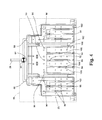
- Figure 4 is a top view of another example of a liquid distribution header of the fabric treating appliance of Figure 1 .
- Figure 5 is a schematic illustration of a portion of the dispenser drawer and a portion of the water distributor of the laundry treating appliance of Figure 1 .
- FIG. 1 schematically illustrates a first embodiment of the invention in the environment of a fabric treating appliance, such as a laundry treating appliance in the form of a clothes washer 10 comprising a housing 12, which may be a cabinet, chassis, or both, defining an interior.
- the laundry treating appliance is a horizontal axis washing machine; however, the laundry treating appliance may be any appliance which performs a cycle of operation on laundry, non-limiting examples of which include a vertical-axis washing machine; a horizontal or vertical axis clothes dryer; a combination washing machine and clothes dryer; a tumbling or stationary refreshing/revitalizing machine; an extractor; and a revitalizing machine.
- the term "horizontal-axis" washing machine refers to a washing machine having a rotatable drum that rotates about a generally horizontal axis relative to a surface that supports the washing machine.
- the drum may rotate about the axis inclined relative to the horizontal axis, with fifteen degrees of inclination being one example of the inclination.
- vertical-axis washing machine refers to a washing machine having a rotatable drum that rotates about a generally vertical axis relative to a surface that supports the washing machine.
- the rotational axis need not be perfectly vertical to the surface.
- the drum may rotate about an axis inclined relative to the vertical axis, with fifteen degrees of inclination being one example of the inclination.
- the clothes washer 10 described herein shares many features of a traditional automatic washing machine, which will not be described in detail except as necessary for a complete understanding of the invention. Further, it should be understood that the invention may be adapted for use with other appliances, such as dishwashers, employing a dispensing system.
- a tub 14 may be provided in the interior of the housing 12 and may be configured to hold liquid.
- the tub 14 may be supported within the housing 12 by a suitable suspension system (not shown).
- a drum 16 may be provided within the tub 14 and may define a treating chamber 15 for receiving fabric, such as laundry to be treated according to a cycle of operation.
- the drum 16 may be mounted for rotation within the tub 14.
- the drum 14 may have perforations that permit the flow of water between the drum 16 and the tub 14.
- the tub 14 and drum 16 may have aligned openings that provide access to the treating chamber 15.
- a door (not shown) may be provided to selectively close at least one of the aligned openings to selectively provide access to the treating chamber 15.
- a dispensing system illustrated as a treating chemistry dispenser 20 may be provided within the housing 12 and may include at least one treating chemistry reservoir 22, a liquid distribution header, such as a water distributor 23, and a dispenser housing 24.
- One or more treating chemistries may be provided in the treating chemistry reservoir 22 in any desirable configuration, such as a single charge, multiple charge (also known as bulk dispenser), or both. Examples of typical treating chemistries include, without limitation, water, detergent, bleach, fabric softener, and enzymes.
- the treating chemistry dispensing system 20 may be configured to meter the treating chemistry as required for a particular cycle of operation.
- a liquid such as water may be supplied from a water source, such as a household water supply 27, to the treating chemistry dispensing system 20 by operation of a valve 26 controlling the flow of water through a conduit 28.
- An outlet conduit 29 extends from the treating chemistry dispensing system 20 to the tub 14.
- any treating chemistry supplied from the treating chemistry dispensing system 20 may be supplied to the tub 14 via the outlet conduit 29.
- a liquid recirculation system may be provided for recirculating liquid to the treating chamber 15.
- the recirculation system includes a recirculation pump 30 and a spray conduit 32.
- the recirculation pump 30 fluidly couples the tub 14 to the spray conduit such that liquid in the tub 14 may be supplied to the spray conduit 32, where it may be sprayed into the treating chamber 15.
- the recirculation pump 30 may be located in a low portion or sump of the tub 14.
- a liquid drain system may be provided for draining liquid from the treating chamber 15.
- the liquid draining system may include a drain pump 40 and a drain conduit 42.
- the drain pump 40 fluidly couples the tub 14 to the drain conduit 42 such that liquid in the tub 14 may be drained via the drain conduit 42.
- the drain conduit 42 may be coupled to a household drain.
- the drain pump 40 may be located in a low portion or sump of the tub 14.
- a controller 45 may be provided for controlling the operation of the various components of the laundry treating appliance 10 to implement one or more cycles of operation, which may be stored in a memory of the controller 45. Examples, without limitation, of cycles of operation include: wash, heavy duty wash, delicate wash, quick wash, refresh, rinse only, and timed wash. Any suitable controller 45 may be used. The specific type of controller is not germane to the invention. It is contemplated that the controller 45 may be a microprocessor-based controller that implements control software and sends/receives one or more electrical signals to/from each of the various components to affect the control software.
- proportional control P
- proportional integral control PI
- proportional derivative control PD
- P proportional integral derivative control
- controller 45 may be operably coupled to at least the water supply valve 26, the dispensing system 20, the recirculation pump 30, the drain pump 40, and a motor (not shown) that rotates the drum 16 to control the operation of these and other components to implement one or more of the cycles of operation.
- the treating chemistry dispensing system 20 may be provided on an exterior or interior of the housing 12 and may be immediately accessible by the user or hidden behind a cover, such as a drawer 21 or an access panel as illustrated in Figure 2 . Further, the treating chemistry dispensing system 20 may include multiple treating chemistry reservoirs 22, which are supplied a liquid stream such as water from the water distributor 23 to flush the contents from the reservoirs into the tub. These multiple treating chemistry reservoirs define cups 49, 50, and 51.
- Each cup 49, 50, 51 includes a siphon tube 54 (shown partially in phantom) that extends above and below the bottom wall of each cup 49, 50, 51 and the longitudinal axis defined by the siphon tube 54 is generally perpendicular to a vertical axis and the bottom wall of each cup 49, 50, 51.
- the siphon tube 54 may be surrounded by a siphon sump 52 formed in the bottom wall of each cup 49, 50, 51.
- the portion of the siphon tube 54 extending above the bottom and into the cup 49, 50, 51 may be received within a siphon cover 56.
- the siphon cover 56 may include a sleeve with a periphery that covers additional portions of the siphon tube 54.
- the siphon tube 54 forms a siphon device for removal of the treating chemistry solution from each cup 49, 50, 51 during operation of the treating chemistry dispensing system 20.
- the siphon tube 54 may be fluidly coupled to the dispenser housing 24 and the treating chamber 15 such that the treating chemistry solution may be dispensed to the treating chamber 15.
- FIG. 3 illustrates that the water distributor 23 may include multiple water inlets 62, 64, and 66, water outlet holes 70 and 72, water outlet slots 74, and raised portions 80 and raised nibs 82.
- Each of the water inlets 62, 64, and 66 may correspond to a separate portion of the water distributor 23 which in turn distributes water to each of the cups 49, 50, and 51 respectively.
- the water inlets 62, 64, and 66 are fluidly coupled to the conduit 28 through a valve 26 which may selectively distribute water to each of the cups 49, 50, and 51 by selectively controlling the flow of water through the water inlets 62, 64, and 66. More specifically, when water is introduced through water inlet 64 it may travel through water outlet holes 70 and 72 and water outlet slots 74 to cup 50.
- the raised portions 80 and raised nibs 82 help to channel the flow of water from the water inlet 64 to the liquid stream outlet holes 70 and 72 and water outlet slots 74.
- FIG 4 illustrates another example of the liquid distribution header with a different configuration of holes and slots than the water distributor of Figure 3 .
- the water distributor 23 may include multiple water inlets 62, 64, and 66, water outlet holes 86, 90, 92, and 96, water outlet slots 94, raised outlet holes 106, raised portions 100, and raised nibs 102.
- the water distributor 23 shown here may include shorter water outlet slots 94 compared to the water outlet slots 74 of the distributor of Figure 3 .
- the raised outlet holes 106 by providing a barrier around the hole, may provide for a different flow of the water there through compared to the holes 90, 92, and 96. The flow through the raised outlet holes 106 may be less than the flow through the holes 90, 92, and 96.
- Each of the water inlets 62, 64, and 66 may correspond to a separate portion of the water distributor 23 which in turn distributes water to each of the cups 49, 50, and 51 respectively.
- Water inlets 62, 64, and 66 are fluidly coupled to the conduit 28 through a valve 26 which may selectively distribute the water to each of the cups 49, 50, and 51 by selectively controlling the flow of the water through the water inlets 62, 64, and 66.
- the raised portions 100, raised nibs 102, and the walls of the raised outlet holes 106 help to channel the flow of water from the water inlet 64 to the water outlet holes 86, 90, 92, 96, the hole of the raised outlet hole 106, and water outlet slots 94.
- the at least one treating chemistry reservoir 22 stores a single dose of treating chemistry that the treating chemistry dispensing system 20 may dispense to the tub 14, as part of the execution of the cleaning cycle; i.e., typically the entire volume of chemistry contained within the at least one treating chemistry reservoir 22 is dispensed into the tub 14 during a single cleaning cycle.
- FIG. 5 illustrates the operation of either one of the water distributor 23 described in conjunction with Figures 3 and 4 .
- Water may flow through the water inlet 64 and into the water distributor 23. The water may then flow through the water outlet holes 70, 72, 86, 90, and 92 and water outlet slots 74 and 94 to cup 50.
- the small diameter of the water outlet holes 70, 72, 86, 90, and 92 creates a stream of water with a small flow and a high velocity.
- the water outlet holes 70 and 90 may be positioned such that the water flowing from them impinges on and keeps the siphon sump 52 and portions of the cup adjacent the siphon tube 54 clean of any debris.
- the water outlet holes 72 and 92 may be positioned such that the water flowing from impinges upon and keeps the top of the siphon cover 56 clean of any debris.
- the larger area of the water outlet slots 74 and 94, as compared to the water outlet holes 70, 72, 86, 90, and 92 provides for a greater flow of water to enter the cup 50 under a slightly lower velocity and in more of a shower or spray pattern, as compared to the discrete jet produced by the water outlet holes 70, 72, 86, 90, and 92 and the raised outlet holes 106.
- the shape of the water outlet slots 74 and 94 also provide for the water to spray in a forward direction instead of straight down as with the water outlet holes 70, 72, 86, 90, and 92.
- the forward velocity of the spray may provide for greater turbulence and mixing when the water contacts the detergent contained in each of the cups 49, 50, and 51 without creating excess sudsing.
- This shower spray pattern and the forward spray direction of the spray coming from the water outlet slots 74 and 94 on either side of the water outlet hole 70 and 90 function to keep the area under the siphon cover 56 clean because the water from the water outlet slots 74 and 94 contacts the bottom of the cups 49, 50, and 51 and spreads out and cleans the bottom of the cups 49, 50, and 51.
- the shower like spray and its forward directional spray also provides for the spray to pass under and not be blocked by the siphon cover 56.
- the shower like spray may be able to spray both the siphon tube 54 and any sleeve that the siphon cover 56 may have.
- liquid stream outlet holes 70 and 72 and liquid stream outlet slots 74 are two outlet openings that introduce two different liquid streams downwardly into the cups 49, 50, and 51 from a position above the siphon cover 56 and along a generally vertical trajectory.
- the liquid stream may be either a continuous stream or a discontinuous stream.
- the water outlet slots 74 and 94 also provide the additional functionality of limiting the amount of suds produced by the incoming water that is sprayed into each of the cups 49, 50, and 51 by limiting the velocity of the water as compared to the jets of water from the water outlet holes 70, 72, 86, 90, and 92.
- the higher velocity of the water entering the cups tends to increase the amount of suds.
- the lower velocity of the water from the water outlet slots 74 and 94 reduces the amount of suds that would be present if holes were used instead of the slots.
- the additional suds may create cross flow into the outer cups.
- the treating chemistry dispensing system 20 is especially advantageous when any of the cups 49, 50, and 51 contains a powder detergent. Powder tends to solidify in cooler temperatures, such as a cold water wash, and it tends to stick to the bottom of the cups 49, 50, and 51 when the cups 49, 50, and 51 contain residual water from a previous cycle.
- a siphon tube 54 there will be residual water in the cups 49, 50, and 51 due to the water held vertically between the siphon cover 56 and the siphon tube 54.
- a high velocity shower is one way to remove the residual or dried powder, but it tends to generate more suds than desired.
- the water outlet slots 74 and 94 have a larger surface area than typical outlet holes which results in a lower velocity shower than the spray from the holes, but a spray that still has a high enough velocity to remove the residual powder while providing reduced aeration, by having a portion of its spray velocity in a direction parallel to the bottom of the cups 49, 50, and 51 and thereby creating fewer suds.
- the treating chemistry reservoir 22 can be used with either liquid or powder detergent dispensed through a siphon tube 54 into the treating chamber 15.
- the siphon tube 54 is fluidly coupled to the outlet conduit 29.
- the siphon tube 54 also allows the benefit of the powder detergent time to more uniformly mix with the liquid stream delivered via the water distributor 23 before the mixture proceeds to the outlet conduit and into the treating chamber 15.
Landscapes
- Engineering & Computer Science (AREA)
- Textile Engineering (AREA)
- Detail Structures Of Washing Machines And Dryers (AREA)
- Accessory Of Washing/Drying Machine, Commercial Washing/Drying Machine, Other Washing/Drying Machine (AREA)
Abstract
A fabric treating appliance comprising:
a treating chamber for receiving the fabric for treatment;
a treating chemistry dispenser comprising:
at least one cup with a bottom wall;
a siphon tube projecting upwardly from the bottom wall and having an inlet opening above the bottom wall, with an inlet opening fluidly coupled to the treating chamber;
a cover for the siphon tube; and
a liquid distribution header located above the cover and having at least one of a first type of outlet opening configured to introduce a liquid stream into the cup from a position above and beyond a periphery of the cover and downwardly along a trajectory terminating below and within the periphery of the cover, wherein the liquid stream directly impinges a portion of at least one of the cup and siphon tube below the cover
and a method of operating the fabric treating appliance. The detergent dispenser is flushed with a water flow for removal of residual powder while reducing sudsing.
a treating chamber for receiving the fabric for treatment;
a treating chemistry dispenser comprising:
at least one cup with a bottom wall;
a siphon tube projecting upwardly from the bottom wall and having an inlet opening above the bottom wall, with an inlet opening fluidly coupled to the treating chamber;
a cover for the siphon tube; and
a liquid distribution header located above the cover and having at least one of a first type of outlet opening configured to introduce a liquid stream into the cup from a position above and beyond a periphery of the cover and downwardly along a trajectory terminating below and within the periphery of the cover, wherein the liquid stream directly impinges a portion of at least one of the cup and siphon tube below the cover
and a method of operating the fabric treating appliance. The detergent dispenser is flushed with a water flow for removal of residual powder while reducing sudsing.
Description
- Laundry treating appliances, such as clothes washers, clothes dryers, refreshers, and non-aqueous systems, may be provided with a dispenser for automatically dispensing one or more treating chemistries during a cleaning cycle. Such dispensers are well-known devices for receiving powder and/or liquid treating chemistries, such as detergents, bleach, and fabric softeners, and dispensing the treating chemistries into a treating chamber during an operation cycle of the laundry treating appliance. Such dispensers typically have one or more dispensing cups that may be filled with only enough treating chemistry, i.e. a "charge" or "dose", for a single cleaning cycle. The cups are usually designated for only a powder treating chemistry or a liquid treating chemistry. Users have been known to fill the cup with the wrong type of treating chemistry and this may cause problems within the dispenser.
- Typically, water is flushed through the cup to dispense the treating chemistry into the treating chamber. The water may not fully remove the treating chemistry from the cup or there may be poor mixing of the treating chemistry and the water. The residual treating chemistry may negatively impact the efficacy of the next treating chemistry placed in the cup or may undesirably alter the dosage of the same treating chemistry in a subsequent dose.
- The invention relates to a fabric treating appliance and a method for treating fabric where a liquid stream is introduced into a dispensing cup from a position above the cup and beyond a periphery of a cover over a siphon tube in the cup, with the liquid stream traveling downwardly along a trajectory terminating below and within the periphery of the cover, wherein the liquid stream directly impinges a portion of at least one of the cup and siphon tube below the cover.
- The invention will be further described by way of example with reference to the accompanying drawings, in which:-
-
Figure 1 is a schematic illustration of a fabric treating appliance in the form of a laundry treating appliance according to a first embodiment of the invention. -
Figure 2 is a perspective view of the dispenser drawer of the laundry treating appliance ofFigure 1 . -
Figure 3 is a top view of a liquid distribution header functioning as a water distributor for the laundry treating appliance ofFigure 1 . -
Figure 4 is a top view of another example of a liquid distribution header of the fabric treating appliance ofFigure 1 . -
Figure 5 is a schematic illustration of a portion of the dispenser drawer and a portion of the water distributor of the laundry treating appliance ofFigure 1 . -
Figure 1 schematically illustrates a first embodiment of the invention in the environment of a fabric treating appliance, such as a laundry treating appliance in the form of aclothes washer 10 comprising ahousing 12, which may be a cabinet, chassis, or both, defining an interior. As illustrated, the laundry treating appliance is a horizontal axis washing machine; however, the laundry treating appliance may be any appliance which performs a cycle of operation on laundry, non-limiting examples of which include a vertical-axis washing machine; a horizontal or vertical axis clothes dryer; a combination washing machine and clothes dryer; a tumbling or stationary refreshing/revitalizing machine; an extractor; and a revitalizing machine. As used herein, the term "horizontal-axis" washing machine refers to a washing machine having a rotatable drum that rotates about a generally horizontal axis relative to a surface that supports the washing machine. The drum may rotate about the axis inclined relative to the horizontal axis, with fifteen degrees of inclination being one example of the inclination. Similar to the horizontal axis washing machine, the term "vertical-axis" washing machine refers to a washing machine having a rotatable drum that rotates about a generally vertical axis relative to a surface that supports the washing machine. However, the rotational axis need not be perfectly vertical to the surface. The drum may rotate about an axis inclined relative to the vertical axis, with fifteen degrees of inclination being one example of the inclination. Theclothes washer 10 described herein shares many features of a traditional automatic washing machine, which will not be described in detail except as necessary for a complete understanding of the invention. Further, it should be understood that the invention may be adapted for use with other appliances, such as dishwashers, employing a dispensing system. - A
tub 14 may be provided in the interior of thehousing 12 and may be configured to hold liquid. Thetub 14 may be supported within thehousing 12 by a suitable suspension system (not shown). Adrum 16 may be provided within thetub 14 and may define a treatingchamber 15 for receiving fabric, such as laundry to be treated according to a cycle of operation. Thedrum 16 may be mounted for rotation within thetub 14. Thedrum 14 may have perforations that permit the flow of water between thedrum 16 and thetub 14. - The
tub 14 anddrum 16 may have aligned openings that provide access to the treatingchamber 15. A door (not shown) may be provided to selectively close at least one of the aligned openings to selectively provide access to the treatingchamber 15. - A dispensing system illustrated as a treating
chemistry dispenser 20 may be provided within thehousing 12 and may include at least one treatingchemistry reservoir 22, a liquid distribution header, such as awater distributor 23, and adispenser housing 24. One or more treating chemistries may be provided in the treatingchemistry reservoir 22 in any desirable configuration, such as a single charge, multiple charge (also known as bulk dispenser), or both. Examples of typical treating chemistries include, without limitation, water, detergent, bleach, fabric softener, and enzymes. The treatingchemistry dispensing system 20 may be configured to meter the treating chemistry as required for a particular cycle of operation. - A liquid such as water may be supplied from a water source, such as a
household water supply 27, to the treating chemistry dispensingsystem 20 by operation of avalve 26 controlling the flow of water through aconduit 28. Anoutlet conduit 29 extends from the treating chemistry dispensingsystem 20 to thetub 14. Thus, any treating chemistry supplied from the treatingchemistry dispensing system 20 may be supplied to thetub 14 via theoutlet conduit 29. - A liquid recirculation system may be provided for recirculating liquid to the treating
chamber 15. As illustrated, the recirculation system includes arecirculation pump 30 and aspray conduit 32. Therecirculation pump 30 fluidly couples thetub 14 to the spray conduit such that liquid in thetub 14 may be supplied to thespray conduit 32, where it may be sprayed into the treatingchamber 15. Therecirculation pump 30 may be located in a low portion or sump of thetub 14. - A liquid drain system may be provided for draining liquid from the treating
chamber 15. The liquid draining system may include adrain pump 40 and adrain conduit 42. Thedrain pump 40 fluidly couples thetub 14 to thedrain conduit 42 such that liquid in thetub 14 may be drained via thedrain conduit 42. Thedrain conduit 42 may be coupled to a household drain. Thedrain pump 40 may be located in a low portion or sump of thetub 14. - A
controller 45 may be provided for controlling the operation of the various components of thelaundry treating appliance 10 to implement one or more cycles of operation, which may be stored in a memory of thecontroller 45. Examples, without limitation, of cycles of operation include: wash, heavy duty wash, delicate wash, quick wash, refresh, rinse only, and timed wash. Anysuitable controller 45 may be used. The specific type of controller is not germane to the invention. It is contemplated that thecontroller 45 may be a microprocessor-based controller that implements control software and sends/receives one or more electrical signals to/from each of the various components to affect the control software. As an example, proportional control (P), proportional integral control (PI), and proportional derivative control (PD), or a combination thereof, a proportional integral derivative control (PID control), may be used to control the various components. Thecontroller 45 may be operably coupled to at least thewater supply valve 26, thedispensing system 20, therecirculation pump 30, thedrain pump 40, and a motor (not shown) that rotates thedrum 16 to control the operation of these and other components to implement one or more of the cycles of operation. - Looking at the treating chemistry dispensing
system 20 in greater detail, it may be provided on an exterior or interior of thehousing 12 and may be immediately accessible by the user or hidden behind a cover, such as adrawer 21 or an access panel as illustrated inFigure 2 . Further, the treating chemistry dispensingsystem 20 may include multiple treatingchemistry reservoirs 22, which are supplied a liquid stream such as water from thewater distributor 23 to flush the contents from the reservoirs into the tub. These multiple treating chemistry reservoirs definecups cup cup siphon tube 54 is generally perpendicular to a vertical axis and the bottom wall of eachcup siphon tube 54 may be surrounded by asiphon sump 52 formed in the bottom wall of eachcup siphon tube 54 extending above the bottom and into thecup siphon tube 54. Thesiphon tube 54 forms a siphon device for removal of the treating chemistry solution from eachcup chemistry dispensing system 20. Thesiphon tube 54 may be fluidly coupled to thedispenser housing 24 and the treatingchamber 15 such that the treating chemistry solution may be dispensed to the treatingchamber 15. -
Figure 3 illustrates that thewater distributor 23 may includemultiple water inlets water outlet holes water outlet slots 74, and raisedportions 80 and raisednibs 82. Each of thewater inlets water distributor 23 which in turn distributes water to each of thecups conduit 28 through avalve 26 which may selectively distribute water to each of thecups water inlets water inlet 64 it may travel through water outlet holes 70 and 72 andwater outlet slots 74 tocup 50. The raisedportions 80 and raisednibs 82 help to channel the flow of water from thewater inlet 64 to the liquid stream outlet holes 70 and 72 andwater outlet slots 74. -
Figure 4 illustrates another example of the liquid distribution header with a different configuration of holes and slots than the water distributor ofFigure 3 . Thewater distributor 23 may includemultiple water inlets water outlet slots 94, raised outlet holes 106, raisedportions 100, and raisednibs 102. Thewater distributor 23 shown here may include shorterwater outlet slots 94 compared to thewater outlet slots 74 of the distributor ofFigure 3 . The raised outlet holes 106, by providing a barrier around the hole, may provide for a different flow of the water there through compared to theholes holes - Each of the
water inlets water distributor 23 which in turn distributes water to each of thecups Water inlets conduit 28 through avalve 26 which may selectively distribute the water to each of thecups water inlets water inlet 64 it may travel through water outlet holes 86, 90, 92, and 96 andwater outlet slots 94 tocups portions 100, raisednibs 102, and the walls of the raised outlet holes 106 help to channel the flow of water from thewater inlet 64 to the water outlet holes 86, 90, 92, 96, the hole of the raisedoutlet hole 106, andwater outlet slots 94. - Although treating chemistries, in either liquid or powder form, may be provided in any desirable configuration, the remainder of this application will describe only a single charge of treating chemistry. Thus, the at least one treating
chemistry reservoir 22 stores a single dose of treating chemistry that the treatingchemistry dispensing system 20 may dispense to thetub 14, as part of the execution of the cleaning cycle; i.e., typically the entire volume of chemistry contained within the at least one treatingchemistry reservoir 22 is dispensed into thetub 14 during a single cleaning cycle. -
Figure 5 illustrates the operation of either one of thewater distributor 23 described in conjunction withFigures 3 and4 . Water may flow through thewater inlet 64 and into thewater distributor 23. The water may then flow through the water outlet holes 70, 72, 86, 90, and 92 andwater outlet slots cup 50. The small diameter of the water outlet holes 70, 72, 86, 90, and 92 creates a stream of water with a small flow and a high velocity. The water outlet holes 70 and 90 may be positioned such that the water flowing from them impinges on and keeps the siphonsump 52 and portions of the cup adjacent the siphontube 54 clean of any debris. The water outlet holes 72 and 92 may be positioned such that the water flowing from impinges upon and keeps the top of the siphon cover 56 clean of any debris. - The larger area of the
water outlet slots cup 50 under a slightly lower velocity and in more of a shower or spray pattern, as compared to the discrete jet produced by the water outlet holes 70, 72, 86, 90, and 92 and the raised outlet holes 106. The shape of thewater outlet slots cups water outlet slots water outlet hole 70 and 90 function to keep the area under the siphon cover 56 clean because the water from thewater outlet slots cups cups tube 54 and any sleeve that the siphon cover 56 may have. In other words, the liquid stream outlet holes 70 and 72 and liquidstream outlet slots 74 are two outlet openings that introduce two different liquid streams downwardly into thecups - The
water outlet slots cups water outlet slots - The treating
chemistry dispensing system 20 is especially advantageous when any of thecups cups cups tube 54, there will be residual water in thecups tube 54. A high velocity shower is one way to remove the residual or dried powder, but it tends to generate more suds than desired. Thewater outlet slots cups - It should be noted that in
chemistry dispensing system 20, the treatingchemistry reservoir 22 can be used with either liquid or powder detergent dispensed through a siphontube 54 into the treatingchamber 15. The siphontube 54 is fluidly coupled to theoutlet conduit 29. Although the use of a siphontube 54 can result in residual liquid from a previous cycle as described above, the siphontube 54 also allows the benefit of the powder detergent time to more uniformly mix with the liquid stream delivered via thewater distributor 23 before the mixture proceeds to the outlet conduit and into the treatingchamber 15. - While the invention has been specifically described in connection with certain specific embodiments thereof, it is to be understood that this is by way of illustration and not of limitation. Reasonable variation and modification are possible within the scope of the invention as defined in the appended claims.
Claims (15)
- A method of operating a fabric treating appliance comprising a treating chamber and a treating chemistry dispenser having at least one cup with a siphon tube with cover having a periphery, where the siphon tube is fluidly coupled to the treating chamber, the method comprising:introducing a liquid stream into the cup from a position above and beyond the periphery of the cover of the siphon tube and along a trajectory terminating below and within the periphery of the cover; andwherein the liquid stream directly impinges a portion of at least one of the cup and siphon tube below the cover.
- The method of claim 1 wherein the liquid stream comprises a continuous stream.
- The method of claim 1 wherein the liquid stream comprises a discontinuous stream.
- The method of claim 1, 2 or 3, wherein the liquid stream directly impinges on one or more of: (a) a portion of the siphon tube; (b) a portion of the cup adjacent the siphon tube; (c) a junction of the siphon tube and the cup.
- The method of any one of the preceding claims wherein the liquid stream washes away residual detergent beneath the cover.
- The method of any one of the preceding claims wherein the siphon tube defines a longitudinal axis and the trajectory is at an angle relative to the longitudinal axis.
- The method of claim 6 wherein the longitudinal axis comprises a vertical axis.
- The method of claim 7 further comprising introducing a second liquid stream into the cup along an axis generally parallel to the vertical axis.
- The method of claim 8 further comprising introducing the second liquid stream at a location above the cover.
- The method of any one of claims 1 to 7 further comprising introducing a second liquid stream from a position above the cover and downwardly along a vertical trajectory.
- The method of claim 8, 9 or 10, wherein both the liquid stream and the second liquid stream are emitted from a distribution header positioned above the cup.
- A fabric treating appliance comprising:a treating chamber for receiving the fabric for treatment;a treating chemistry dispenser comprising:at least one cup with a bottom wall;a siphon tube projecting upwardly from the bottom wall and having an inlet opening above the bottom wall, with an inlet opening fluidly coupled to the treating chamber;a cover for the siphon tube; anda liquid distribution header located above the cover and having at least one of a first type of outlet opening configured to introduce a liquid stream into the cup from a position above and beyond a periphery of the cover and downwardly along a trajectory terminating below and within the periphery of the cover, wherein the liquid stream directly impinges a portion of at least one of the cup and siphon tube below the cover.
- The fabric treating appliance of claim 12 wherein the liquid distribution header comprises a second type of outlet opening configured to introduce a second liquid stream downwardly into the cup from a position above the cover and along a generally vertical trajectory.
- The fabric treating appliance of claim 13 further comprising a plurality of at least one of the first and second types of outlet openings.
- The fabric treating appliance of claim 12, 13 or 14, wherein the siphon tube defines a longitudinal axis that is generally parallel to a vertical axis.
Applications Claiming Priority (2)
| Application Number | Priority Date | Filing Date | Title |
|---|---|---|---|
| US32381010P | 2010-04-13 | 2010-04-13 | |
| US12/905,133 US9003588B2 (en) | 2010-04-13 | 2010-10-15 | Appliances with sudsing-reducing flushable detergent dispensers |
Publications (1)
| Publication Number | Publication Date |
|---|---|
| EP2377987A1 true EP2377987A1 (en) | 2011-10-19 |
Family
ID=44201172
Family Applications (1)
| Application Number | Title | Priority Date | Filing Date |
|---|---|---|---|
| EP11155870A Withdrawn EP2377987A1 (en) | 2010-04-13 | 2011-02-24 | Laundry treating appliance with detergent dispenser and method of operating it |
Country Status (3)
| Country | Link |
|---|---|
| US (6) | US9003588B2 (en) |
| EP (1) | EP2377987A1 (en) |
| BR (1) | BRPI1101056A2 (en) |
Cited By (7)
| Publication number | Priority date | Publication date | Assignee | Title |
|---|---|---|---|---|
| EP2604743A3 (en) * | 2011-12-14 | 2013-11-06 | Electrolux Home Products Corporation N.V. | Laundry washing machine |
| EP2604744A3 (en) * | 2011-12-14 | 2013-11-06 | Electrolux Home Products Corporation N.V. | Laundry washing machine |
| CN104093897A (en) * | 2011-12-28 | 2014-10-08 | 阿塞里克股份有限公司 | Washing machine including detergent dispenser |
| DE102013223432B3 (en) * | 2013-11-18 | 2014-11-13 | BSH Bosch und Siemens Hausgeräte GmbH | household appliance |
| DE102013225351B3 (en) * | 2013-12-10 | 2015-04-02 | BSH Bosch und Siemens Hausgeräte GmbH | household appliance |
| EP3460119A1 (en) * | 2017-09-20 | 2019-03-27 | Miele & Cie. KG | Suction device for suction of a detergent composition from a flushing box of a washing machine |
| US10648121B2 (en) | 2016-11-17 | 2020-05-12 | Whirlpool Corporation | Laundry treating appliance and dispenser |
Families Citing this family (23)
| Publication number | Priority date | Publication date | Assignee | Title |
|---|---|---|---|---|
| US9127391B2 (en) * | 2011-08-17 | 2015-09-08 | General Electric Company | Device for dispensing an additive in an appliance |
| US10781548B2 (en) | 2014-12-23 | 2020-09-22 | Electrolux Appliances Aktiebolag | Method for operating a laundry washing machine using a unit dose package and laundry washing machine implementing the method |
| CN107109759B (en) * | 2014-12-23 | 2019-10-22 | 伊莱克斯家用电器股份公司 | Method for operating a washing machine using unit dose packs and washing machine |
| KR102551727B1 (en) * | 2016-08-19 | 2023-07-06 | 삼성전자주식회사 | Detergent feeding device and washing machine having the same |
| EP3293302A1 (en) | 2016-09-13 | 2018-03-14 | Electrolux Appliances Aktiebolag | Method for operating a laundry washing machine with a unit dose package and laundry washing machine implementing the method |
| CN107815818A (en) * | 2016-09-14 | 2018-03-20 | 迪尔阿扣基金两合公司 | Distributor and the electrical equipment with the distributor |
| US10280550B2 (en) * | 2016-09-16 | 2019-05-07 | Haier Us Appliance Solutions, Inc. | Fluid additive dispenser |
| US10612181B2 (en) | 2017-04-13 | 2020-04-07 | Whirlpool Corporation | Laundry treating appliance with dispenser having domed bottom |
| US9885136B1 (en) | 2017-04-13 | 2018-02-06 | Whirlpool Corporation | Laundry treating appliance with dispenser having sliding interface for water inlet duct |
| US10584438B2 (en) | 2017-04-13 | 2020-03-10 | Whirlpool Corporation | Laundry treating appliance with dispenser having multiple lids |
| US10988881B2 (en) | 2017-07-06 | 2021-04-27 | Whirlpool Corporation | Fabric cleaning appliance with performance enhancement selector |
| USD863237S1 (en) | 2017-09-22 | 2019-10-15 | Whirlpool Corporation | Push button knob with illumination capabilities for a laundry treating appliance |
| CN109898281B (en) * | 2017-12-08 | 2022-09-09 | 青岛海尔洗涤电器有限公司 | laundry treatment device |
| CN108589204A (en) * | 2018-07-16 | 2018-09-28 | 广东好太太科技集团股份有限公司 | A kind of electric clothes airing machine |
| US11162209B2 (en) | 2018-09-14 | 2021-11-02 | Electrolux Home Products, Inc. | Method for operating a laundry washing machine using a unit dose package and laundry washing machine |
| US11359325B2 (en) | 2018-09-14 | 2022-06-14 | Electrolux Appliances Aktiebolag | Method and apparatus for cleaning laundry |
| US11041267B2 (en) | 2018-09-14 | 2021-06-22 | Electrolux Appliances Aktiebolag | Method and apparatus for cleaning laundry |
| US11066775B2 (en) | 2018-09-14 | 2021-07-20 | Electrolux Appliances Aktiebolag | Method and apparatus for cleaning laundry |
| CN109183360B (en) * | 2018-10-24 | 2022-03-11 | 青岛海尔洗涤电器有限公司 | Detergent box and washing machine with same |
| JP7253894B2 (en) * | 2018-10-30 | 2023-04-07 | 三星電子株式会社 | washing machine |
| WO2020147769A1 (en) * | 2019-01-18 | 2020-07-23 | 青岛海尔滚筒洗衣机有限公司 | Dispensing device for washing |
| US11913156B2 (en) | 2019-07-03 | 2024-02-27 | Electrolux Appliances Aktiebolag | Laundry washing machine for use with unit dose detergent packages |
| US11155951B2 (en) | 2019-07-25 | 2021-10-26 | Electrolux Appliances Aktiebolag | Laundry washing machine for use with unit dose detergent packages |
Citations (5)
| Publication number | Priority date | Publication date | Assignee | Title |
|---|---|---|---|---|
| DE3803196A1 (en) * | 1988-02-03 | 1989-08-17 | Bosch Siemens Hausgeraete | DETERGENT DISCHARGE DEVICE |
| US20030145633A1 (en) * | 2002-02-06 | 2003-08-07 | Merkle Scott A. | Dual use detergent dispenser |
| US20050229652A1 (en) * | 2004-04-14 | 2005-10-20 | Lg Electronics Inc. | Apparatus for supplying detergent in washer |
| DE102008004258A1 (en) * | 2007-03-26 | 2008-10-02 | BSH Bosch und Siemens Hausgeräte GmbH | Household-washing machine, has dispensing pipelines, outlets, circulating pipeline, circulating pump, two way-valve, cylinder, piston and spring, which are provided to remove deposits of washing agent residues by supplying additional water |
| EP2025798A2 (en) * | 2007-07-30 | 2009-02-18 | Miele & Cie. KG | Water supply device for a washing machine and washing machine |
Family Cites Families (49)
| Publication number | Priority date | Publication date | Assignee | Title |
|---|---|---|---|---|
| GB1161216A (en) | 1966-08-31 | 1969-08-13 | Philips Electronic Associated | Improvements in or relating to Domestic Washing Machines. |
| US3481163A (en) * | 1968-05-08 | 1969-12-02 | Gen Electric | Dispensing arrangement for washing machine |
| AT291900B (en) * | 1969-05-17 | 1971-08-10 | Zanussi A Spa Industrie | Detergent and additive dispenser for washing machines |
| GB1289412A (en) | 1970-04-13 | 1972-09-20 | ||
| US3742736A (en) * | 1970-07-17 | 1973-07-03 | Gen Motors Corp | Peripheral fill system for a clothes washer |
| DE2038324B2 (en) | 1970-08-01 | 1978-07-06 | Licentia Patent-Verwaltungs-Gmbh, 6000 Frankfurt | Washing agent flushing equipment in automatic machine - has concave chamber end wall of spherical section |
| GB1330798A (en) | 1972-08-08 | 1973-09-19 | British Domestic Appliances | Liquid dispensers for washing machines |
| US4112590A (en) * | 1975-07-02 | 1978-09-12 | August Lepper, Maschinen- Und Apparatebau Gmbh | Combined drum washer and drying arrangement |
| FR2401259A1 (en) | 1977-08-23 | 1979-03-23 | Thomson Brandt | Automatic washing machine - with treatment liq. distributor comprising various compartments filled at beginning of cycle with treatment liq. |
| FR2503744A1 (en) | 1981-04-14 | 1982-10-15 | Esswein Sa | Washing machines with alternative reservoirs for liq. or powder soap - with split water jets to use either additive form without further adjustment |
| FR2546194B1 (en) | 1983-05-20 | 1986-03-28 | Esswein Sa | WASHING MACHINE OR DISHWASHER EQUIPPED WITH A PRODUCTS BOX |
| DE3403852A1 (en) | 1984-02-03 | 1985-08-14 | Bosch-Siemens Hausgeräte GmbH, 7000 Stuttgart | Automatically controlled washing machine |
| IT8434054V0 (en) | 1984-10-05 | 1984-10-05 | Zanussi Elettrodomestici | DISTRIBUTOR OF LIQUID AND POWDER DETERGENTS FOR WASHING MACHINES. |
| IT8434062V0 (en) | 1984-10-12 | 1984-10-12 | Zanussi Elettrodomestici | DISTRIBUTOR OF LIQUID AND POWDER DETERGENTS FOR WASHING MACHINES. |
| FR2574097B1 (en) | 1984-11-30 | 1987-01-23 | Amiens Const Electro Mec | LIGE WASHING MACHINE HAVING A DUAL-USE WASHING PRODUCTS BOX |
| FR2585739B1 (en) | 1985-08-02 | 1988-09-02 | Amiens Const Elect Mec | LAUNDRY WASHING MACHINE EQUIPPED WITH A DUAL-PURPOSE LAUNDRY POT. |
| IT1187302B (en) | 1985-12-04 | 1987-12-23 | Zanussi Elettrodomestici | DETERGENT CONTAINER-DISPENSER DEVICE FOR WASHING MACHINE |
| DE3608619A1 (en) | 1986-03-14 | 1987-09-17 | Bosch Siemens Hausgeraete | WASHING MACHINE WITH A DETERGENT DISH WASHER |
| DE3608620A1 (en) | 1986-03-14 | 1987-09-24 | Bosch Siemens Hausgeraete | WASHING MACHINE WITH A DETERGENT DISH WASHER |
| IT207655Z2 (en) | 1986-04-30 | 1988-02-08 | Eurodomestici Ind Riunite | DRAWER FOR DETERGENTS WITH NON-INTEGRATED WATER SUPPLY DUCTS, FOR WASHING MACHINE. |
| DE3715832A1 (en) | 1987-05-12 | 1988-11-24 | Bosch Siemens Hausgeraete | DETERGENT DISCHARGE TRAY WITH AUXILIARY DEVICE FOR LIQUID DETERGENT |
| DE3736252A1 (en) | 1987-10-27 | 1989-05-11 | Bauknecht Hausgeraete | Flush-in device for liquid laundry-treatment agents |
| FR2632984B1 (en) | 1988-06-17 | 1991-05-17 | Ciapem | POWDER OR LIQUID PRODUCTS BOX AND WASHING MACHINE PROVIDED WITH SUCH A BOX |
| US5262132A (en) * | 1990-04-30 | 1993-11-16 | Diversey Corporation | Solid detergent dispensing system |
| IT1270426B (en) | 1993-06-07 | 1997-05-05 | Merloni Elettrodomestici Spa | TOP-LOADING WASHING MACHINE, WITH DISPENSER OF WASHING AGENTS IN THE DOOR |
| GB9521719D0 (en) | 1995-10-24 | 1996-01-03 | Gw Chemicals Ltd | Cleaning apparatus |
| DE19724174C1 (en) | 1997-06-09 | 1998-08-06 | Whirlpool Co | Washing machine detergent feed |
| EP1423564B1 (en) | 2001-07-13 | 2007-02-21 | Arçelik A.S. | Washing machine with detergent dispenser |
| ITPN20020016A1 (en) * | 2002-03-19 | 2003-09-19 | Electrolux Home Products Corpo | TANK FOR DETERGENT SUBSTANCES AND WASHING MACHINE INCLUDING THE TANK. |
| CN1282786C (en) | 2002-04-17 | 2006-11-01 | Lg电子有限公司 | Detergent injection device for washing machine |
| EP1479813A1 (en) | 2003-05-21 | 2004-11-24 | AWECO APPLIANCE SYSTEMS GmbH & Co. KG | Household appliance with flushing device for dosing unit |
| KR101013374B1 (en) | 2003-11-10 | 2011-02-14 | 삼성전자주식회사 | Washing machine with detergent supply |
| KR101022224B1 (en) | 2003-11-17 | 2011-03-17 | 삼성전자주식회사 | Washing machine with detergent supply |
| JP2005253507A (en) * | 2004-03-09 | 2005-09-22 | Sanyo Electric Co Ltd | Washing machine |
| KR101082562B1 (en) * | 2004-04-14 | 2011-11-10 | 엘지전자 주식회사 | Water supplying control method of washing machine |
| PL1600546T3 (en) * | 2004-05-25 | 2009-12-31 | Electrolux Home Products Corp Nv | Clothes washing machine with improved water dispensers |
| KR20050118894A (en) | 2004-06-15 | 2005-12-20 | 삼성전자주식회사 | Washing machine having a detergent feeding device |
| CN1746408A (en) | 2004-09-08 | 2006-03-15 | 乐金电子(天津)电器有限公司 | Detergent throwing device of washer |
| DE102005012423A1 (en) * | 2005-03-17 | 2006-09-21 | BSH Bosch und Siemens Hausgeräte GmbH | Method for operating a flushing device |
| KR101233188B1 (en) * | 2005-10-12 | 2013-02-15 | 엘지전자 주식회사 | Detergent box of washing machine |
| FR2910913B1 (en) | 2006-12-27 | 2009-05-29 | Brandt Ind Sas | DETERGENT DISPENSER FOR INTRODUCING AT LEAST ONE DOSE OF DETERGENT, IN PARTICULAR FOR HOUSEHOLD APPLIANCE OF THE WASHING MACHINE TYPE |
| DE102008005363A1 (en) | 2007-04-20 | 2008-10-23 | BSH Bosch und Siemens Hausgeräte GmbH | Washing machine with a device for the portioned addition of detergent active ingredients |
| US7900486B2 (en) * | 2007-08-20 | 2011-03-08 | Whirlpool Corporation | Agent dispenser |
| US9085844B2 (en) * | 2007-11-13 | 2015-07-21 | Electrolux Home Products, Inc. | Sequenced water delivery in an additive dispenser |
| KR101479242B1 (en) | 2008-09-25 | 2015-01-05 | 삼성전자 주식회사 | A detergent supply device and a washing machine including the same |
| KR101010697B1 (en) | 2008-11-17 | 2011-01-24 | 엘지전자 주식회사 | Laundry treatment equipment |
| CN102282307B (en) | 2008-11-17 | 2013-12-25 | Lg电子株式会社 | Washing machine |
| US8074476B2 (en) * | 2009-09-21 | 2011-12-13 | Alliance Laundry Systems Llc | Washer extractor with improved chemical dispenser |
| EP2604744A3 (en) * | 2011-12-14 | 2013-11-06 | Electrolux Home Products Corporation N.V. | Laundry washing machine |
-
2010
- 2010-10-15 US US12/905,133 patent/US9003588B2/en active Active
-
2011
- 2011-02-24 EP EP11155870A patent/EP2377987A1/en not_active Withdrawn
- 2011-03-21 BR BRPI1101056-8A patent/BRPI1101056A2/en not_active Application Discontinuation
-
2015
- 2015-02-13 US US14/621,458 patent/US9695539B2/en active Active
-
2017
- 2017-06-12 US US15/619,692 patent/US10538873B2/en active Active
-
2019
- 2019-12-19 US US16/720,658 patent/US11142861B2/en active Active
- 2019-12-19 US US16/720,855 patent/US11214914B2/en active Active
-
2021
- 2021-12-22 US US17/559,513 patent/US20220112650A1/en not_active Abandoned
Patent Citations (5)
| Publication number | Priority date | Publication date | Assignee | Title |
|---|---|---|---|---|
| DE3803196A1 (en) * | 1988-02-03 | 1989-08-17 | Bosch Siemens Hausgeraete | DETERGENT DISCHARGE DEVICE |
| US20030145633A1 (en) * | 2002-02-06 | 2003-08-07 | Merkle Scott A. | Dual use detergent dispenser |
| US20050229652A1 (en) * | 2004-04-14 | 2005-10-20 | Lg Electronics Inc. | Apparatus for supplying detergent in washer |
| DE102008004258A1 (en) * | 2007-03-26 | 2008-10-02 | BSH Bosch und Siemens Hausgeräte GmbH | Household-washing machine, has dispensing pipelines, outlets, circulating pipeline, circulating pump, two way-valve, cylinder, piston and spring, which are provided to remove deposits of washing agent residues by supplying additional water |
| EP2025798A2 (en) * | 2007-07-30 | 2009-02-18 | Miele & Cie. KG | Water supply device for a washing machine and washing machine |
Cited By (10)
| Publication number | Priority date | Publication date | Assignee | Title |
|---|---|---|---|---|
| EP2604743A3 (en) * | 2011-12-14 | 2013-11-06 | Electrolux Home Products Corporation N.V. | Laundry washing machine |
| EP2604744A3 (en) * | 2011-12-14 | 2013-11-06 | Electrolux Home Products Corporation N.V. | Laundry washing machine |
| CN104093897A (en) * | 2011-12-28 | 2014-10-08 | 阿塞里克股份有限公司 | Washing machine including detergent dispenser |
| DE102013223432B3 (en) * | 2013-11-18 | 2014-11-13 | BSH Bosch und Siemens Hausgeräte GmbH | household appliance |
| DE102013225351B3 (en) * | 2013-12-10 | 2015-04-02 | BSH Bosch und Siemens Hausgeräte GmbH | household appliance |
| EP2883993A1 (en) | 2013-12-10 | 2015-06-17 | BSH Hausgeräte GmbH | Domestic appliance with a pressurized water supply line and a regulating valve |
| US10648121B2 (en) | 2016-11-17 | 2020-05-12 | Whirlpool Corporation | Laundry treating appliance and dispenser |
| US11214911B2 (en) | 2016-11-17 | 2022-01-04 | Whirlpool Corporation | Laundry treating appliance and dispenser |
| US11773527B2 (en) | 2016-11-17 | 2023-10-03 | Whirlpool Corporation | Laundry treating appliance and dispenser |
| EP3460119A1 (en) * | 2017-09-20 | 2019-03-27 | Miele & Cie. KG | Suction device for suction of a detergent composition from a flushing box of a washing machine |
Also Published As
| Publication number | Publication date |
|---|---|
| US20200123694A1 (en) | 2020-04-23 |
| US9003588B2 (en) | 2015-04-14 |
| US11142861B2 (en) | 2021-10-12 |
| US20200123693A1 (en) | 2020-04-23 |
| US10538873B2 (en) | 2020-01-21 |
| US20110247147A1 (en) | 2011-10-13 |
| US20220112650A1 (en) | 2022-04-14 |
| US11214914B2 (en) | 2022-01-04 |
| BRPI1101056A2 (en) | 2012-08-21 |
| US9695539B2 (en) | 2017-07-04 |
| US20170275806A1 (en) | 2017-09-28 |
| US20150159313A1 (en) | 2015-06-11 |
Similar Documents
| Publication | Publication Date | Title |
|---|---|---|
| US11214914B2 (en) | Appliances with sudsing-reducing flushable detergent dispensers | |
| US8713737B2 (en) | Method and apparatus for dispensing treating chemistry in a laundry treating appliance | |
| US11603621B2 (en) | Household cleaning appliance with a non-bulk dispensing system convertible to a household cleaning appliance with a bulk dispensing system | |
| US7900486B2 (en) | Agent dispenser | |
| US10231597B2 (en) | Household cleaning appliance with a single water flow path for both non-bulk and bulk dispensing | |
| US10422073B2 (en) | Laundry washing machine equipped with a treating agents dispenser having water supplying apparatus | |
| US10351985B2 (en) | Method and apparatus for rinsing laundry in a laundry treating appliance | |
| US7426932B2 (en) | Spray fill device and method for using the same | |
| US10253444B2 (en) | Integrated single dose and bulk dispenser for a laundry treating appliance | |
| US12247343B2 (en) | Household appliance with single-use dispenser for bulk dispenser filling | |
| US9103062B2 (en) | Appliance with features for preventing additive drying | |
| US20180119328A1 (en) | Dispenser for a laundry treating household appliance having a float diverter | |
| KR20130010363A (en) | A washing machine and a methoed for jetting washing water of the washing machine | |
| US20050056060A1 (en) | Washing machine with improved washing-aid dispenser | |
| KR20050121051A (en) | Washing machine |
Legal Events
| Date | Code | Title | Description |
|---|---|---|---|
| AK | Designated contracting states |
Kind code of ref document: A1 Designated state(s): AL AT BE BG CH CY CZ DE DK EE ES FI FR GB GR HR HU IE IS IT LI LT LU LV MC MK MT NL NO PL PT RO RS SE SI SK SM TR |
|
| AX | Request for extension of the european patent |
Extension state: BA ME |
|
| PUAI | Public reference made under article 153(3) epc to a published international application that has entered the european phase |
Free format text: ORIGINAL CODE: 0009012 |
|
| 17P | Request for examination filed |
Effective date: 20120130 |
|
| STAA | Information on the status of an ep patent application or granted ep patent |
Free format text: STATUS: THE APPLICATION HAS BEEN WITHDRAWN |
|
| 18W | Application withdrawn |
Effective date: 20170124 |