EP2377387A2 - Konkave Einstellungsanordnung mit einer Torsionsachse zum Dämpfen der Getreidedreschimpulsbelastung - Google Patents
Konkave Einstellungsanordnung mit einer Torsionsachse zum Dämpfen der Getreidedreschimpulsbelastung Download PDFInfo
- Publication number
- EP2377387A2 EP2377387A2 EP10160384A EP10160384A EP2377387A2 EP 2377387 A2 EP2377387 A2 EP 2377387A2 EP 10160384 A EP10160384 A EP 10160384A EP 10160384 A EP10160384 A EP 10160384A EP 2377387 A2 EP2377387 A2 EP 2377387A2
- Authority
- EP
- European Patent Office
- Prior art keywords
- concave
- threshing system
- inner element
- damping elements
- drive
- Prior art date
- Legal status (The legal status is an assumption and is not a legal conclusion. Google has not performed a legal analysis and makes no representation as to the accuracy of the status listed.)
- Granted
Links
Images

Classifications
-
- A—HUMAN NECESSITIES
- A01—AGRICULTURE; FORESTRY; ANIMAL HUSBANDRY; HUNTING; TRAPPING; FISHING
- A01F—PROCESSING OF HARVESTED PRODUCE; HAY OR STRAW PRESSES; DEVICES FOR STORING AGRICULTURAL OR HORTICULTURAL PRODUCE
- A01F12/00—Parts or details of threshing apparatus
- A01F12/18—Threshing devices
- A01F12/28—Devices for adjusting the concaves
-
- A—HUMAN NECESSITIES
- A01—AGRICULTURE; FORESTRY; ANIMAL HUSBANDRY; HUNTING; TRAPPING; FISHING
- A01F—PROCESSING OF HARVESTED PRODUCE; HAY OR STRAW PRESSES; DEVICES FOR STORING AGRICULTURAL OR HORTICULTURAL PRODUCE
- A01F12/00—Parts or details of threshing apparatus
- A01F12/18—Threshing devices
- A01F12/181—Adjustable threshing mechanisms
Definitions
- This invention relates generally to apparatus for adjustably supporting a concave of threshing apparatus of an agricultural combine, and more particularly, to a concave adjust assembly utilizing a torsion axle for damping impulse or shock loads generated from threshing crops.
- An agricultural combine generally includes a threshing system including at least one concave disposed about a threshing rotor of the system.
- a gap will be located between the concave and rotor, and is desirably variable for accommodating different crops and conditions. In particular, it has become a desirable feature to have a capability to remotely adjust the gap just before and during operation of the combine.
- concave adjust assemblies or mechanisms have been developed to allow concave gap adjustments to be made by the combine operator or another person using a suitable input device or switch, located in the operator cabin or another location, and some systems allow the adjustments to be made automatically.
- Such adjust assemblies or mechanisms typically include a motor in driven relation to a gear train in connection with the concave, operation of which can be used for precisely adjusting or setting the concave gap.
- threshing forces generated by the rotation of the rotor and resulting impacts with the crop material during threshing can be transmitted through the concave and the apparatus in support thereof, e.g., linkages, cross bar, etc., to elements of the concave adjust assembly, resulting in breakage and/or failure thereof. It has been found that the threshing forces, particularly those resulting from intermittently occurring plugs or slugs of crop material, can translate into repeating impulse or shock loads which have a jack hammering effect on the adjust assembly elements of the adjust assembly which can cause fatigue failures over time.
- a concave adjust assembly which provides a desired concave adjustability, and which includes a torsion axle for absorbing impulse or shock loads, and thus overcomes one or more of the problems set forth above.
- the torsion axle includes an elongate inner element having an angular sectional shape and opposite longitudinal ends configured for connection to spaced apart portions of a threshing system concave.
- An elongate tubular outer element is disposed about the inner element and also has an angular sectional shape, but is of larger sectional extent than the inner element.
- the tubular outer element is oriented relative to the inner element such that corner portions of an inner surface of the outer element are disposed in generally opposing relation to flat portions of an outer surface of the inner element and define spaces therebetween, and such that the outer element and the inner element are laterally relatively rotatable.
- the torsion axle includes elongate resilient damping or biasing elements disposed in the spaces between the inner and outer elements, respectively, such that when the lateral relative rotation of the inner and outer elements occurs, the inner and outer elements will bear against the damping elements to load them in compression.
- the adjust assembly additionally includes a drive having a gear mounted on an outer surface of the tubular outer element, enmeshed with a gear on an output shaft of a motor fixedly mountable to structure of a combine such as a housing of the threshing system, such that operation of the motor will relatively rotate the enmeshed gears.
- the motor can be operated for adjusting the position of the concave relative to an adjacent rotor. Then, as slugs or other impulse or shock load generating conditions are encountered during threshing, the resulting impulse or shock loads will be transmitted through the inner element to the damping elements so as to be damped and dissipated, to substantially reduce or prevent transmission of potentially damage causing impulse loads to the outer element of the torsion axle, and thus to the drive.
- the composition and construction of the damping elements can be selected such that loads exerted thereagainst by just the weight of the concave will not result in significant deformation thereof, to enable precise adjustments of the concave position, and such that any deformation of the damping elements caused by the exertion of the impulse loads thereagainst will be distributed and in a direction which only minimally affects the concave setting, and will be effectively damped and dissipated.
- the inner and outer elements of the torsion axle can be of rectangular sectional shape, and the damping elements can comprise cords of a resilient biasing material, such as an elastomeric material, such as natural and/or synthetic rubber, of a selected firmness which provides the required or desired damping capability.
- a resilient biasing material such as an elastomeric material, such as natural and/or synthetic rubber
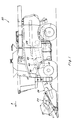
- a representative self-propelled combine 20 including a threshing system 22 constructed and operable for threshing crop material cut by a header 24 and conveyed to threshing system 22 via a feeder 26, as combine 20 moves in a forward direction, denoted by an arrow A, over a field, in the well known manner.
- threshing system 22 includes at least one elongate, generally cylindrical rotor 28 rotatable about a longitudinal axis thereof within, and relative to, a cylindrical tube or housing 30, a lower portion of which housing 30 comprises a concave 32.
- Concave 32 is typically constructed so as to have a plurality of orifices or apertures therethrough, sized for passage of crops, e.g., grain, legumes, etc., therethrough, as well as smaller particles and elements of crop material other than grain (MOG), en route to a cleaning system of combine 20 disposed below threshing system 22, again, in the well known manner.
- crops e.g., grain, legumes, etc.
- MOG crop material other than grain
- a concave such as concave 32
- a concave 32 will be configured and supported hingedly on one side and on the other side so as to be movable generally radially relative to rotor 28 for adjusting a space or gap 34 between an outer cylindrical surface 36 of rotor 28, and an inner cylindrical surface 38 of concave 32, as is also well known.
- Harvested crop material will be formed into a mat as it enters the threshing system so as to essentially wrap about rotor 28 within gap 34 and so as to be conveyed by the rotation of rotor 28 in a helical manner through gap 34, for separating the grain and smaller elements of MOG from larger elements of the MOG, e.g., straw, stalks, cob fragments, etc., which are then discharged from the rear end of the threshing system.
- larger elements of the MOG e.g., straw, stalks, cob fragments, etc.
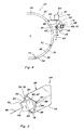
- Prior art concave adjust assembly 40 includes a drive 42 fixedly supported by an inverted U-shape bracket 44 in cantilever relation on a side of housing 30 of threshing system 22, or other fixed structure of combine 20 above and radially outwardly of concave 32.
- Concave adjust assembly 40 additionally includes an elongate axle 46 of suitable material such as tubular or bar steel, supported for lateral rotation about a longitudinal axis therethrough by brackets 48 on housing 30 or other suitable structure of the combine, so as to extend in a generally fore and aft direction just above and outwardly of concave 32, and below drive 42.
- Drive 42 includes a motor 50, which is typically an electrically powered stepping motor or actuator, having a rotatable output 52, which here is a gear train including an output gear 54 which is a worm gear.
- Gear 54 is enmeshed with a gear 56 extending partially about axle 46.
- the ends of axle 46 include cantilever arms 58 fixed thereto, which are connected by linkages 60 to opposite ends of concave 32, for supporting that side of the concave.
- motor 50 of assembly 40 is configured so as to be controllably operated to rotate output 52, to relatively rotate gears 54 and 56, and thus axle 46, in either direction, as denoted by arrow 62 in FIG. 3 .
- the rotation of axle 46 in a clockwise direction will adjustably lift concave 32, as denoted by arrow B, to move it closer to rotor 28, and thereby reduce gap 34, while rotation in the counterclockwise direction will lower the concave (arrow C) to increase gap 34.
- motor 50 When a desired concave position and gap have been achieved, motor 50 will hold the concave in that position. At essentially all times, a portion of the weight of concave 32 will exert a static downwardly directed force FW, which will be transmitted through linkages 60 to arms 58, and thus to axle 46 of assembly 40. Force FW will thus be transmitted by axle 46 to gear 56 thereon, to urge rotation of gear 56 in the counterclockwise direction, denoted by the upwardly directed portion of arrow 62, so as to be opposed or supported by motor 50.
- Pressures exerted by a crop mat (not shown) within gap 34 will exert forces in the same direction, depending on the density and consistency of the mat, so as also to be opposed by motor 50. Thus, normally, these forces will oppose any lifting movements of concave 32 by motor 50, and will result in application of shear loads on the teeth of gears 54 and 56, and, because of the mounting arrangement of motor 50, bending loads on bracket 44.
- impulse forces denoted by arrows FI in FIG. 3 , which are transmitted by concave 32 to linkages 60, and by linkages 60 to arms 58, to axle 46, and to the above described elements of drive 40, e.g., gears 54, 56, motor 50 and bracket 44.
- impulse loads can be generated in rapid and sustained succession, so as to have a jack hammer effect on drive 40, or they can be intermittent.
- the levels of the loads can also vary, as a function of various factors, such as rotor speed, crop loads, composition of a slug or rock, stone or the like. As a result, fatigue and other failure of components of drive 40 have been found to occur, including, but not limited to, bracket 44.
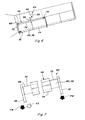
- Concave adjust assembly 64 constructed and operable according to the teachings of the present invention, for resisting damage from jack hammer impulse loads and overcoming the failure related problems discussed above, is shown, like parts of concave assembly 64 and assembly 40 being identified by like parts.
- Concave adjust assembly 64 includes a drive 42 mounted by a bracket 44 to housing 30 in the above described manner, drive 42 including a motor 50 having an output 52, including a gear 54 enmeshed with a gear 56.
- gear 56 is mounted on an elongate torsion axle 66 of the invention which differs in important ways from axle 46.
- torsion axle 66 includes an elongate inner element 68 of a suitable material such as steel, having an angular sectional shape and opposite longitudinal ends 70 and 72 in connection with linkages 60 connecting to opposite ends of concave 32.
- Torsion axle 66 includes an elongate tubular outer element 74, also of a suitable material such as steel, disposed about inner element 68, outer element 74 having an angular sectional shape having a larger sectional extent or size than a sectional extent or size of inner element 68.
- outer element 74 is oriented in angular offset relation to inner element 68 such that corner portions 76 of an inner surface 78 of outer element 74 are disposed in generally opposing relation to flat portions 80 of an outer surface 82 of inner element 68, defining spaces 84 therebetween, as best shown in FIGS. 5 and 9 .
- inner and outer elements 68 and 74 preferably each have a rectangular shape and more preferably a square shape, such that spaces 84 are generally triangular shaped.
- elements 68 and 74 are relatively rotatable laterally, that is, generally about a longitudinal axis 86 therethrough ( FIG. 5 ).
- Torsion axle 66 includes elongate resilient damping elements 88 disposed in spaces 84, respectively, such that forces urging the lateral relative rotation of outer element 74 and inner element 68 will act to exert compression forces against damping elements 88, respectively.
- damping elements are preferably elongate cords of a resilient elastomeric material such as, but not limited to, a natural rubber, synthetic rubber, or a mixture of the two, although it should be recognized that other elastomeric polymers or other compositions could be used.
- loads such as the portion of the weight FW of concave 32, and impulse forces FI ( FIG. 7 )
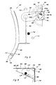
- loads will be transmitted via linkages 60 to arms 58, so as to act to pull arms 58 downwardly, as best illustrated in FIG. 8 .
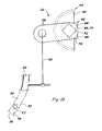
- This loading will be transmitted to ends 70 and 72 of inner element 68, as denoted by torques TFW and TFI, respectively, which urge element 68 to rotate in the counterclockwise direction as shown, relative to outer element 74.
- torques TFW and TFI respectively
- a force FO generated by drive 42 which will exert an equal counteracting torque TO, as required for holding concave 32 in a selected position, as also shown in FIG. 8 .
- Drive 42 is capable of generating a force FO exceeding force FW which in the absence of force FI will act to lift the concave for reducing gap 34, and a reduced force FO to allow the concave to lower to increase the gap.
- Damping elements 88 are configured and disposed about inner element 68 for resiliently opposing relative rotation of elements 68 and 74, and preferably, to largely resist significant physical deformation when subjected to just loads LW exerted by the weight of the concave, to enable precisely setting gap 34.
- damping elements 88 which can correspond to the length of torsion axle 64, and which can be over one meter (several feet).
- Damping elements 88 are configured to deform to a greater but still limited extent when subjected to loads LI of greater magnitudes, as illustrated in FIG. 9 , which is beneficial so as to absorb and damp loads LI, and prevent or substantially reduce transmission thereof past outer element 74, such that those forces that reach drive 42 will be of lower magnitude, again though, such that any changes to gap 34 will be minimal.
- the effects of impulse loads LI transmitted through outer element 74 to gears 54 and 56 are significantly reduced, so as to correspondingly reduce occurrence of consequential damage to the gears, as well as other components of drive 42, including bracket 44.
- torsion axle 64 will typically have a length of over one meter (several feet).
- Impulse loads generated during threshing can be exerted against axle 64 unevenly from end to end.
- an impulse loading condition may initially be exerted primarily against end 70 and move from end 70 toward end 72 of inner element 68 as a slug of material progresses along concave 32.
- Inner element 68 can be configured so as to also be resiliently twistable to a limited extent, as illustrated, so as to be capable of absorbing and damping such loads or a portion of the loads. This can be advantageous to distribute the loads more along the torsion axle, and also to minimize deformation of damping elements 88 and thus reduce any movement of concave 32.
- the torsion axle can be configured such that the inner element is connected to the drive, and the outer element connected to the concave.
- the motor in operation, with the outer element of the torsion axle connected in support of a concave, and the inner element connected to the drive, the motor can still be operated for adjusting the position of the concave relative to an adjacent rotor. Then, as slugs or other impulse or shock load generating conditions are encountered during threshing, the resulting impulse or shock loads will be transmitted through the outer element to the damping elements so as to be damped and dissipated, to substantially reduce or prevent transmission of potentially damage causing impulse loads to the inner element of the torsion axle, and thus to the drive.
Landscapes
- Life Sciences & Earth Sciences (AREA)
- Environmental Sciences (AREA)
- Vibration Prevention Devices (AREA)
Applications Claiming Priority (1)
| Application Number | Priority Date | Filing Date | Title |
|---|---|---|---|
| US42587810A | 2010-04-17 | 2010-04-17 |
Publications (3)
| Publication Number | Publication Date |
|---|---|
| EP2377387A2 true EP2377387A2 (de) | 2011-10-19 |
| EP2377387A3 EP2377387A3 (de) | 2012-09-12 |
| EP2377387B1 EP2377387B1 (de) | 2018-09-05 |
Family
ID=44209957
Family Applications (1)
| Application Number | Title | Priority Date | Filing Date |
|---|---|---|---|
| EP10160384.3A Active EP2377387B1 (de) | 2010-04-17 | 2010-04-19 | Konkave Einstellungsanordnung mit einer Torsionsachse zum Dämpfen der Getreidedreschimpulsbelastung |
Country Status (1)
| Country | Link |
|---|---|
| EP (1) | EP2377387B1 (de) |
Cited By (1)
| Publication number | Priority date | Publication date | Assignee | Title |
|---|---|---|---|---|
| US10015930B2 (en) | 2015-12-10 | 2018-07-10 | Cnh Industrial America Llc | Positioning and safety apparatus suitable for control of concave suspension in a combine harvester |
Family Cites Families (3)
| Publication number | Priority date | Publication date | Assignee | Title |
|---|---|---|---|---|
| US2625784A (en) * | 1948-10-22 | 1953-01-20 | Cadwallader W Kelsey | Multiple windrowing disk type mower |
| DE10242579A1 (de) * | 2002-09-11 | 2005-03-17 | Claas Selbstfahrende Erntemaschinen Gmbh | Einrichtung zum Absorbieren von Schwingunggen in einer landwirtschaftlichen Erntemaschine |
| US7393274B2 (en) * | 2006-02-01 | 2008-07-01 | Agco Corporation | Combine harvester processing system having adjustable members |
-
2010
- 2010-04-19 EP EP10160384.3A patent/EP2377387B1/de active Active
Non-Patent Citations (1)
| Title |
|---|
| None |
Cited By (1)
| Publication number | Priority date | Publication date | Assignee | Title |
|---|---|---|---|---|
| US10015930B2 (en) | 2015-12-10 | 2018-07-10 | Cnh Industrial America Llc | Positioning and safety apparatus suitable for control of concave suspension in a combine harvester |
Also Published As
| Publication number | Publication date |
|---|---|
| EP2377387B1 (de) | 2018-09-05 |
| EP2377387A3 (de) | 2012-09-12 |
Similar Documents
| Publication | Publication Date | Title |
|---|---|---|
| US7803040B1 (en) | Concave adjust assembly including a torsion axle for damping crop threshing impulse loads | |
| US20100083629A1 (en) | Flexible cutterbar support apparatus with integral adjustable torsional preload mechanism and vibration damper | |
| US8141331B2 (en) | Divider support apparatus with integral adjustable torsional preload mechanism and vibration damper | |
| EP2072191A1 (de) | Handwerkzeugmaschine | |
| DE112010002057T5 (de) | Antriebseinheitsschwingungsdämpfungsstütze für ein elektromotorbetriebenes Fahrzeug | |
| US11483971B2 (en) | Cutter bar support linkage | |
| EP2377387B1 (de) | Konkave Einstellungsanordnung mit einer Torsionsachse zum Dämpfen der Getreidedreschimpulsbelastung | |
| US6779326B2 (en) | Spring system for feeder rollers in forage harvesters | |
| GB1586768A (en) | Rotary cultivators | |
| DE2453171A1 (de) | Befestigungsanordnung | |
| EP1932420A1 (de) | Siebträgerstruktur für einen Mähdrescher | |
| EP3530105B1 (de) | Einstell- und aufhängevorrichtung für dreschkorb | |
| WO2008028652A1 (de) | Schwingungserreger | |
| EP2153079B1 (de) | Elastische wellenkupplung mit adaptiver charakteristik | |
| US20150336623A1 (en) | Mount for a cabin of an agricultural harvester | |
| CN107864753A (zh) | 带喂料器的玉米脱粒机 | |
| DE10361294A1 (de) | Antivibrationselement | |
| EP1411174B1 (de) | Bodenverdichtungsvorrichtung | |
| DE102008033922B4 (de) | Häckselaggregat für Feldhäcksler | |
| DE202009004301U1 (de) | Bodenverdichtungsvorrichtung mit schwingungsisolierter Deichsel | |
| US4342187A (en) | Resonant sickle drive with spring means at opposite ends of the sickle | |
| WO2021052936A1 (de) | Schneidwerk mit blattfederpaket als schneidelementträger | |
| EP1380203B1 (de) | Massendurchsatzmessgerät für einen Mähdrescher | |
| EP1653112B1 (de) | Aufsammeleinrichtung zum Aufnehmen von am Boden liegendem Erntegut | |
| DE20307433U1 (de) | Bodenverdichtungsvorrichtung |
Legal Events
| Date | Code | Title | Description |
|---|---|---|---|
| AK | Designated contracting states |
Kind code of ref document: A2 Designated state(s): AT BE BG CH CY CZ DE DK EE ES FI FR GB GR HR HU IE IS IT LI LT LU LV MC MK MT NL NO PL PT RO SE SI SK SM TR |
|
| AX | Request for extension of the european patent |
Extension state: AL BA ME RS |
|
| PUAI | Public reference made under article 153(3) epc to a published international application that has entered the european phase |
Free format text: ORIGINAL CODE: 0009012 |
|
| PUAL | Search report despatched |
Free format text: ORIGINAL CODE: 0009013 |
|
| AK | Designated contracting states |
Kind code of ref document: A3 Designated state(s): AT BE BG CH CY CZ DE DK EE ES FI FR GB GR HR HU IE IS IT LI LT LU LV MC MK MT NL NO PL PT RO SE SI SK SM TR |
|
| AX | Request for extension of the european patent |
Extension state: AL BA ME RS |
|
| RIC1 | Information provided on ipc code assigned before grant |
Ipc: A01F 12/28 20060101ALI20120808BHEP Ipc: A01F 12/18 20060101AFI20120808BHEP |
|
| 17P | Request for examination filed |
Effective date: 20130312 |
|
| RAP1 | Party data changed (applicant data changed or rights of an application transferred) |
Owner name: CNH INDUSTRIAL BELGIUM NV |
|
| GRAP | Despatch of communication of intention to grant a patent |
Free format text: ORIGINAL CODE: EPIDOSNIGR1 |
|
| STAA | Information on the status of an ep patent application or granted ep patent |
Free format text: STATUS: GRANT OF PATENT IS INTENDED |
|
| INTG | Intention to grant announced |
Effective date: 20180323 |
|
| GRAS | Grant fee paid |
Free format text: ORIGINAL CODE: EPIDOSNIGR3 |
|
| GRAA | (expected) grant |
Free format text: ORIGINAL CODE: 0009210 |
|
| STAA | Information on the status of an ep patent application or granted ep patent |
Free format text: STATUS: THE PATENT HAS BEEN GRANTED |
|
| AK | Designated contracting states |
Kind code of ref document: B1 Designated state(s): AT BE BG CH CY CZ DE DK EE ES FI FR GB GR HR HU IE IS IT LI LT LU LV MC MK MT NL NO PL PT RO SE SI SK SM TR |
|
| REG | Reference to a national code |
Ref country code: GB Ref legal event code: FG4D |
|
| REG | Reference to a national code |
Ref country code: CH Ref legal event code: EP |
|
| REG | Reference to a national code |
Ref country code: AT Ref legal event code: REF Ref document number: 1036758 Country of ref document: AT Kind code of ref document: T Effective date: 20180915 |
|
| REG | Reference to a national code |
Ref country code: IE Ref legal event code: FG4D |
|
| REG | Reference to a national code |
Ref country code: DE Ref legal event code: R096 Ref document number: 602010053252 Country of ref document: DE |
|
| REG | Reference to a national code |
Ref country code: NL Ref legal event code: MP Effective date: 20180905 |
|
| REG | Reference to a national code |
Ref country code: LT Ref legal event code: MG4D |
|
| PG25 | Lapsed in a contracting state [announced via postgrant information from national office to epo] |
Ref country code: GR Free format text: LAPSE BECAUSE OF FAILURE TO SUBMIT A TRANSLATION OF THE DESCRIPTION OR TO PAY THE FEE WITHIN THE PRESCRIBED TIME-LIMIT Effective date: 20181206 Ref country code: NO Free format text: LAPSE BECAUSE OF FAILURE TO SUBMIT A TRANSLATION OF THE DESCRIPTION OR TO PAY THE FEE WITHIN THE PRESCRIBED TIME-LIMIT Effective date: 20181205 Ref country code: SE Free format text: LAPSE BECAUSE OF FAILURE TO SUBMIT A TRANSLATION OF THE DESCRIPTION OR TO PAY THE FEE WITHIN THE PRESCRIBED TIME-LIMIT Effective date: 20180905 Ref country code: FI Free format text: LAPSE BECAUSE OF FAILURE TO SUBMIT A TRANSLATION OF THE DESCRIPTION OR TO PAY THE FEE WITHIN THE PRESCRIBED TIME-LIMIT Effective date: 20180905 Ref country code: BG Free format text: LAPSE BECAUSE OF FAILURE TO SUBMIT A TRANSLATION OF THE DESCRIPTION OR TO PAY THE FEE WITHIN THE PRESCRIBED TIME-LIMIT Effective date: 20181205 Ref country code: LT Free format text: LAPSE BECAUSE OF FAILURE TO SUBMIT A TRANSLATION OF THE DESCRIPTION OR TO PAY THE FEE WITHIN THE PRESCRIBED TIME-LIMIT Effective date: 20180905 |
|
| REG | Reference to a national code |
Ref country code: AT Ref legal event code: MK05 Ref document number: 1036758 Country of ref document: AT Kind code of ref document: T Effective date: 20180905 |
|
| PG25 | Lapsed in a contracting state [announced via postgrant information from national office to epo] |
Ref country code: HR Free format text: LAPSE BECAUSE OF FAILURE TO SUBMIT A TRANSLATION OF THE DESCRIPTION OR TO PAY THE FEE WITHIN THE PRESCRIBED TIME-LIMIT Effective date: 20180905 Ref country code: LV Free format text: LAPSE BECAUSE OF FAILURE TO SUBMIT A TRANSLATION OF THE DESCRIPTION OR TO PAY THE FEE WITHIN THE PRESCRIBED TIME-LIMIT Effective date: 20180905 Ref country code: ES Free format text: LAPSE BECAUSE OF FAILURE TO SUBMIT A TRANSLATION OF THE DESCRIPTION OR TO PAY THE FEE WITHIN THE PRESCRIBED TIME-LIMIT Effective date: 20180905 |
|
| PG25 | Lapsed in a contracting state [announced via postgrant information from national office to epo] |
Ref country code: RO Free format text: LAPSE BECAUSE OF FAILURE TO SUBMIT A TRANSLATION OF THE DESCRIPTION OR TO PAY THE FEE WITHIN THE PRESCRIBED TIME-LIMIT Effective date: 20180905 Ref country code: CZ Free format text: LAPSE BECAUSE OF FAILURE TO SUBMIT A TRANSLATION OF THE DESCRIPTION OR TO PAY THE FEE WITHIN THE PRESCRIBED TIME-LIMIT Effective date: 20180905 Ref country code: PL Free format text: LAPSE BECAUSE OF FAILURE TO SUBMIT A TRANSLATION OF THE DESCRIPTION OR TO PAY THE FEE WITHIN THE PRESCRIBED TIME-LIMIT Effective date: 20180905 Ref country code: AT Free format text: LAPSE BECAUSE OF FAILURE TO SUBMIT A TRANSLATION OF THE DESCRIPTION OR TO PAY THE FEE WITHIN THE PRESCRIBED TIME-LIMIT Effective date: 20180905 Ref country code: IS Free format text: LAPSE BECAUSE OF FAILURE TO SUBMIT A TRANSLATION OF THE DESCRIPTION OR TO PAY THE FEE WITHIN THE PRESCRIBED TIME-LIMIT Effective date: 20190105 Ref country code: NL Free format text: LAPSE BECAUSE OF FAILURE TO SUBMIT A TRANSLATION OF THE DESCRIPTION OR TO PAY THE FEE WITHIN THE PRESCRIBED TIME-LIMIT Effective date: 20180905 Ref country code: EE Free format text: LAPSE BECAUSE OF FAILURE TO SUBMIT A TRANSLATION OF THE DESCRIPTION OR TO PAY THE FEE WITHIN THE PRESCRIBED TIME-LIMIT Effective date: 20180905 |
|
| PG25 | Lapsed in a contracting state [announced via postgrant information from national office to epo] |
Ref country code: SK Free format text: LAPSE BECAUSE OF FAILURE TO SUBMIT A TRANSLATION OF THE DESCRIPTION OR TO PAY THE FEE WITHIN THE PRESCRIBED TIME-LIMIT Effective date: 20180905 Ref country code: SM Free format text: LAPSE BECAUSE OF FAILURE TO SUBMIT A TRANSLATION OF THE DESCRIPTION OR TO PAY THE FEE WITHIN THE PRESCRIBED TIME-LIMIT Effective date: 20180905 Ref country code: PT Free format text: LAPSE BECAUSE OF FAILURE TO SUBMIT A TRANSLATION OF THE DESCRIPTION OR TO PAY THE FEE WITHIN THE PRESCRIBED TIME-LIMIT Effective date: 20190105 |
|
| REG | Reference to a national code |
Ref country code: DE Ref legal event code: R097 Ref document number: 602010053252 Country of ref document: DE |
|
| PLBE | No opposition filed within time limit |
Free format text: ORIGINAL CODE: 0009261 |
|
| STAA | Information on the status of an ep patent application or granted ep patent |
Free format text: STATUS: NO OPPOSITION FILED WITHIN TIME LIMIT |
|
| PG25 | Lapsed in a contracting state [announced via postgrant information from national office to epo] |
Ref country code: DK Free format text: LAPSE BECAUSE OF FAILURE TO SUBMIT A TRANSLATION OF THE DESCRIPTION OR TO PAY THE FEE WITHIN THE PRESCRIBED TIME-LIMIT Effective date: 20180905 |
|
| 26N | No opposition filed |
Effective date: 20190606 |
|
| PG25 | Lapsed in a contracting state [announced via postgrant information from national office to epo] |
Ref country code: SI Free format text: LAPSE BECAUSE OF FAILURE TO SUBMIT A TRANSLATION OF THE DESCRIPTION OR TO PAY THE FEE WITHIN THE PRESCRIBED TIME-LIMIT Effective date: 20180905 |
|
| REG | Reference to a national code |
Ref country code: CH Ref legal event code: PL |
|
| PG25 | Lapsed in a contracting state [announced via postgrant information from national office to epo] |
Ref country code: LU Free format text: LAPSE BECAUSE OF NON-PAYMENT OF DUE FEES Effective date: 20190419 Ref country code: MC Free format text: LAPSE BECAUSE OF FAILURE TO SUBMIT A TRANSLATION OF THE DESCRIPTION OR TO PAY THE FEE WITHIN THE PRESCRIBED TIME-LIMIT Effective date: 20180905 |
|
| PG25 | Lapsed in a contracting state [announced via postgrant information from national office to epo] |
Ref country code: LI Free format text: LAPSE BECAUSE OF NON-PAYMENT OF DUE FEES Effective date: 20190430 Ref country code: CH Free format text: LAPSE BECAUSE OF NON-PAYMENT OF DUE FEES Effective date: 20190430 |
|
| PG25 | Lapsed in a contracting state [announced via postgrant information from national office to epo] |
Ref country code: TR Free format text: LAPSE BECAUSE OF FAILURE TO SUBMIT A TRANSLATION OF THE DESCRIPTION OR TO PAY THE FEE WITHIN THE PRESCRIBED TIME-LIMIT Effective date: 20180905 |
|
| PG25 | Lapsed in a contracting state [announced via postgrant information from national office to epo] |
Ref country code: IE Free format text: LAPSE BECAUSE OF NON-PAYMENT OF DUE FEES Effective date: 20190419 |
|
| PG25 | Lapsed in a contracting state [announced via postgrant information from national office to epo] |
Ref country code: CY Free format text: LAPSE BECAUSE OF FAILURE TO SUBMIT A TRANSLATION OF THE DESCRIPTION OR TO PAY THE FEE WITHIN THE PRESCRIBED TIME-LIMIT Effective date: 20180905 |
|
| PG25 | Lapsed in a contracting state [announced via postgrant information from national office to epo] |
Ref country code: HU Free format text: LAPSE BECAUSE OF FAILURE TO SUBMIT A TRANSLATION OF THE DESCRIPTION OR TO PAY THE FEE WITHIN THE PRESCRIBED TIME-LIMIT; INVALID AB INITIO Effective date: 20100419 Ref country code: MT Free format text: LAPSE BECAUSE OF FAILURE TO SUBMIT A TRANSLATION OF THE DESCRIPTION OR TO PAY THE FEE WITHIN THE PRESCRIBED TIME-LIMIT Effective date: 20180905 |
|
| PG25 | Lapsed in a contracting state [announced via postgrant information from national office to epo] |
Ref country code: MK Free format text: LAPSE BECAUSE OF FAILURE TO SUBMIT A TRANSLATION OF THE DESCRIPTION OR TO PAY THE FEE WITHIN THE PRESCRIBED TIME-LIMIT Effective date: 20180905 |
|
| PGFP | Annual fee paid to national office [announced via postgrant information from national office to epo] |
Ref country code: BE Payment date: 20230420 Year of fee payment: 14 |
|
| PGFP | Annual fee paid to national office [announced via postgrant information from national office to epo] |
Ref country code: GB Payment date: 20230420 Year of fee payment: 14 |
|
| GBPC | Gb: european patent ceased through non-payment of renewal fee |
Effective date: 20240419 |
|
| REG | Reference to a national code |
Ref country code: BE Ref legal event code: MM Effective date: 20240430 |
|
| PG25 | Lapsed in a contracting state [announced via postgrant information from national office to epo] |
Ref country code: BE Free format text: LAPSE BECAUSE OF NON-PAYMENT OF DUE FEES Effective date: 20240430 |
|
| PG25 | Lapsed in a contracting state [announced via postgrant information from national office to epo] |
Ref country code: GB Free format text: LAPSE BECAUSE OF NON-PAYMENT OF DUE FEES Effective date: 20240419 |
|
| PG25 | Lapsed in a contracting state [announced via postgrant information from national office to epo] |
Ref country code: GB Free format text: LAPSE BECAUSE OF NON-PAYMENT OF DUE FEES Effective date: 20240419 Ref country code: BE Free format text: LAPSE BECAUSE OF NON-PAYMENT OF DUE FEES Effective date: 20240430 |
|
| PGFP | Annual fee paid to national office [announced via postgrant information from national office to epo] |
Ref country code: DE Payment date: 20250428 Year of fee payment: 16 |
|
| PGFP | Annual fee paid to national office [announced via postgrant information from national office to epo] |
Ref country code: IT Payment date: 20250422 Year of fee payment: 16 |
|
| PGFP | Annual fee paid to national office [announced via postgrant information from national office to epo] |
Ref country code: FR Payment date: 20250424 Year of fee payment: 16 |