EP2376172B1 - Systeme und verfahren für eine konvektionsverstärkte freisetzungsvorrichtung - Google Patents
Systeme und verfahren für eine konvektionsverstärkte freisetzungsvorrichtung Download PDFInfo
- Publication number
- EP2376172B1 EP2376172B1 EP10700628.0A EP10700628A EP2376172B1 EP 2376172 B1 EP2376172 B1 EP 2376172B1 EP 10700628 A EP10700628 A EP 10700628A EP 2376172 B1 EP2376172 B1 EP 2376172B1
- Authority
- EP
- European Patent Office
- Prior art keywords
- catheter
- adapter
- clip
- receiving channel
- grooves
- Prior art date
- Legal status (The legal status is an assumption and is not a legal conclusion. Google has not performed a legal analysis and makes no representation as to the accuracy of the status listed.)
- Not-in-force
Links
- 238000000034 method Methods 0.000 title description 12
- 238000003780 insertion Methods 0.000 claims description 28
- 230000037431 insertion Effects 0.000 claims description 28
- 210000002105 tongue Anatomy 0.000 claims description 16
- 239000003814 drug Substances 0.000 claims description 7
- 230000003993 interaction Effects 0.000 claims description 7
- 230000008878 coupling Effects 0.000 claims description 5
- 238000010168 coupling process Methods 0.000 claims description 5
- 238000005859 coupling reaction Methods 0.000 claims description 5
- 230000037361 pathway Effects 0.000 claims description 5
- 239000006185 dispersion Substances 0.000 claims description 3
- 238000007917 intracranial administration Methods 0.000 claims description 3
- 210000001519 tissue Anatomy 0.000 description 37
- 239000012530 fluid Substances 0.000 description 10
- 238000001802 infusion Methods 0.000 description 4
- 239000000463 material Substances 0.000 description 4
- 239000000853 adhesive Substances 0.000 description 3
- 230000001070 adhesive effect Effects 0.000 description 3
- 210000000988 bone and bone Anatomy 0.000 description 3
- 210000003169 central nervous system Anatomy 0.000 description 3
- 238000012377 drug delivery Methods 0.000 description 3
- 230000008901 benefit Effects 0.000 description 2
- 230000001684 chronic effect Effects 0.000 description 2
- 239000000126 substance Substances 0.000 description 2
- 229940124597 therapeutic agent Drugs 0.000 description 2
- 239000004593 Epoxy Substances 0.000 description 1
- 206010028980 Neoplasm Diseases 0.000 description 1
- 230000000712 assembly Effects 0.000 description 1
- 238000000429 assembly Methods 0.000 description 1
- 230000008499 blood brain barrier function Effects 0.000 description 1
- 210000001218 blood-brain barrier Anatomy 0.000 description 1
- 230000003247 decreasing effect Effects 0.000 description 1
- 210000004207 dermis Anatomy 0.000 description 1
- 238000009792 diffusion process Methods 0.000 description 1
- 229940079593 drug Drugs 0.000 description 1
- 229920005570 flexible polymer Polymers 0.000 description 1
- 238000002347 injection Methods 0.000 description 1
- 239000007924 injection Substances 0.000 description 1
- 238000007913 intrathecal administration Methods 0.000 description 1
- 238000001990 intravenous administration Methods 0.000 description 1
- 239000002184 metal Substances 0.000 description 1
- 239000007769 metal material Substances 0.000 description 1
- 229940126701 oral medication Drugs 0.000 description 1
- 229920000642 polymer Polymers 0.000 description 1
- 239000002861 polymer material Substances 0.000 description 1
- 230000008569 process Effects 0.000 description 1
- 230000001681 protective effect Effects 0.000 description 1
- 210000004761 scalp Anatomy 0.000 description 1
- 239000007787 solid Substances 0.000 description 1
- 230000009885 systemic effect Effects 0.000 description 1
- 230000001225 therapeutic effect Effects 0.000 description 1
- 238000002560 therapeutic procedure Methods 0.000 description 1
Images





Classifications
-
- A—HUMAN NECESSITIES
- A61—MEDICAL OR VETERINARY SCIENCE; HYGIENE
- A61M—DEVICES FOR INTRODUCING MEDIA INTO, OR ONTO, THE BODY; DEVICES FOR TRANSDUCING BODY MEDIA OR FOR TAKING MEDIA FROM THE BODY; DEVICES FOR PRODUCING OR ENDING SLEEP OR STUPOR
- A61M25/00—Catheters; Hollow probes
- A61M25/01—Introducing, guiding, advancing, emplacing or holding catheters
- A61M25/02—Holding devices, e.g. on the body
- A61M2025/024—Holding devices, e.g. on the body having a clip or clamp system
Definitions
- the present invention relates to a convection-enhanced delivery system for use in any targeted drug delivery procedure including convection-enhanced delivery (CED) and chronic intracranial administrations such a system is disclosed in the WO2008119041 .
- CED is the continuous injection under positive pressure of a fluid containing a therapeutic agent.
- This technique is especially useful for administering therapeutic agents to tissues that are inaccessible via traditional oral medications or venous infusion techniques.
- CNS central nervous system
- drug delivery by systemic or by intrathecal methods is not very effective because of the blood-brain barrier and limitations with regard to the drug diffusion into the tissue.
- traditional methods of treatment result in incomplete, non-targeted and heterogeneous dispersion throughout the CNS.
- CED may be used to overcome some of the restrictions associated with traditional and other delivery systems.
- CED utilizes a pressure gradient to infuse substances directly into the interstitial space of a target tissue, for example a solid tumor tissue, via a catheter. This process is known as interstitial infusion and relies on bulk, convective flow and can be used to distribute both small and large molecular weight substances over clinically relevant volumes within solid tissue. Additional benefits include the ability to deliver the therapeutic at relatively constant concentrations throughout the volume of distribution.
- the present invention relates to a convection-enhanced delivery system for use in any targeted drug delivery procedure including convection-enhanced delivery (CED) and chronic intracranial administrations as further disclosed in claim 1.
- the present invention provides a delivery device that includes a generally planar mounting surface for attaching the delivery device to an external surface of a patient.
- a target tissue of the patient is first accessed by providing an aperture in the patient via a drill bit or burr.
- the delivery device is then positioned on the patient such that an aperture in the base member is centered on top of the access aperture of the patient.
- the delivery device is then secured to the external surface of the patient via a plurality of fasteners, such as screws or an adhesive.
- the aperture of the base member provides a pathway through the base member through which a catheter is inserted to access the target tissue of the patient, via the patient aperture.
- the base member further includes a hinged clip that selectively moves between an opened position and a closed position.
- the opened position of the hinged clip exposes the aperture through the base thereby enabling a catheter to be inserted through the aperture and into the target tissue to a desired insertion depth.
- the hinged clip is selectively moved to and locked in a closed position to secure the insertion depth of the catheter in the target tissue.
- the closed position of the hinged clip repositions an adapter portion of the catheter from a vertical orientation to a horizontal orientation. The horizontal orientation reduces the distance between the adapter portion of the catheter and the patient, thereby reducing the vertical profile of the delivery device and inserted catheter.
- the base member further includes a receiving channel for receiving and securing the adapter portion of the catheter when the delivery device is in a closed position.
- An inner surface of the receiving channel may include features for adjustably interacting with an outer surface of the catheter adapter.
- the inner surface of the receiving channel includes a plurality of tongues that fit within a plurality of grooves located on an external surface of the catheter adapter.
- the inner surface of the receiving channel includes a contour or feature that mirrors an external surface of the catheter adapter. The interaction of the receiving channel and the catheter adapter retain the catheter adapter within the receiving channel at various positions within the receiving channel.
- the insertion depth of the catheter in the target tissue is adjusted by selectively positioning the catheter adapter within the receiving channel.
- compatible features between abutting surfaces of the receiving channel and the catheter adapter enable precise and predetermined insertion depths of the catheter within the target tissue.
- a semi-flexible, metallic catheter is used in conjunction with the delivery device.
- a flexible, polymer based catheter is used with the delivery device, thereby requiring the use of a trocar or introducer needle to insert the catheter into the target tissue.
- a micromanipulator is coupled to a portion of the catheter adapter to provide control and accuracy for insertion of the catheter into the target tissue.
- the delivery system 10 comprises a base 12 that includes a generally planar mounting surface 14 that interfaces directly with an outer surface 16 of a patient 18.
- the mounting surface 14 of the base 12 is arched or otherwise shaped to conform to a non-planar external surface 16.
- a non-planar external surface 16 is made planar by removing excess external surface 16 material.
- the planar mounting surface 14 is positioned on the external surface 16 and secured thereto via a plurality of fasteners 50.
- the base 12 comprises a flexible or semi-rigid material that contours to the non-planar external surface 16.
- the base portion 12 of the delivery device 10 is contoured and held in a contoured configuration by securing the device 10 to the external surface 16 via the plurality of fasteners 50.
- the plurality of fasteners 50 may include any device or combination of devices sufficient to maintain an interface between the base 12 and the external surface 16 of the patient 18.
- the plurality of fasteners 50 comprises bone screws.
- the plurality of fasteners 50 comprises an adhesive, such as an epoxy, or an adhesive strip (not shown).
- the delivery device 10 is attached directly to the bone 20 of the patient 18 via fasteners 50.
- the delivery device 10 is placed directly on the dermis (not shown) of the patient 18 and secured to the patient 18 via fasteners 50 that are anchored into the bone 20.
- the fasteners 50 are generally inserted through an aperture 22 of the base, wherein a head portion of the fastener 50 binds on a chamfered surface of the aperture 22 to secure the position of the delivery device 10.
- a proximal end 30 of the base 12 further comprises a hinged clip 40.
- the clip 40 is hingedly anchored to the base 12 via a stationary stator 24 and pin 26.
- the clip 40 further comprises an outer surface 42 and an inner surface 44.
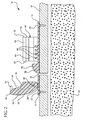
- the outer surface 42 may comprise any shape or contour that maintains a low profile when the clip 40 is in a closed position, as illustrated in Figure 1 .
- the outer surface 42 is gently arched and is free from sharp edges that may snag or otherwise catch on clothing or hair of the patient 18.
- the outer surface 42 further comprises a ledge feature 46 for interlockedly coupling with a clip catch 62 feature of the delivery device 10. The coupling of the ledge feature 46 and the clip catch 62 hold the clip 40 in a closed and locked position, as shown in Figures 1 and 7 .
- the inner surface 44 is generally contoured to form an arched surface 48.
- the radius of the arched surface 48 is selected to provide a gentle angle by which an uninserted portion 76 of a catheter 72 is bent in a non-occluding manner.
- the base 12 further comprises a catheter support 90 having a contoured support surface 92 that mirrors the arched surface 48 of the clip 40. As such, the uninserted portion 76 of the catheter 72 is interposedly held between the clip 40 and the catheter support 90 at a desired radial (angle). When in the closed position, the clip 40 and the catheter support 90 assist to maintain the position of the inserted portion 78 of the catheter 72 within the target tissue 28.
- the outer surface 42 of the clip 40 further comprises a pair of catheter guards 52 that straddle an unsupported portion of the catheter 76.
- the catheter guards 52 generally comprise a gap interposed between the two guards 52 into which a portion of the uninserted portion 76 of the catheter 72 is inserted upon positioning the clip 40 in a closed configuration. The catheter guards 52 thus hold the uninserted portion 76 of the catheter 72 to prevent lateral movement of the catheter 76 with respect to the clip 40 and catheter support 90.
- a distal end 32 of the base further comprises a receiving channel 60.
- the receiving channel 60 generally comprises a pair of opposing walls 64 that attach to the base 12 to provide a three-sided channel.
- the opposing walls 64 are generally parallel and spaced apart so as to accommodate insertion of a catheter adapter 74 therein.
- an inner surface of the opposing walls 64 is recessed 68 or otherwise contoured to compatibly receive an outwardly extended surface 82 of the catheter adapter 74, as illustrated in Figures 3 , 6 , and 8 .
- a portion of the inner surface of the opposing walls 64 is extended inwardly into the channel 60 to provide a lip 84.
- the opposing lips 84 generally provide an opening to the channel 60 that is slightly narrower than the width of the catheter adapter 74.
- the outer surface of the catheter adapter 74 contacts the opposing lips 84 to outwardly bias the opposing walls 64 during insertion of the catheter adapter 74 within the channel 60.
- the portion of the channel 60 defined by the base 12 further comprises a plurality of tongues 66 extending upwardly from the base 12.
- the plurality of tongues 66 provide a spaced surface which is adjustably fitted into a plurality of grooves 80 located on a catheter adapter portion 74 of a catheter assembly 70.
- the interaction between the plurality of tongues 66 and the plurality of grooves 80 enables varied placement of the catheter adapter 74 within the receiving channel 60. As such, the insertion depth of the inserted portion 78 of the catheter 72 is determined by the position of the catheter adapter 74 within the receiving channel 60.
- the catheter adapter 74 of the catheter assembly 70 further includes a fluid chamber 86 and fluid inlet 88, as is conventional with intravenous catheters.
- Other features of the catheter adapter 74 include a plug 96 and a sealed pathway 98 through which a trocar 110 or introducer needle is inserted, in some embodiments (see Figure 8 ).
- the catheter 72 material is a semi-flexible polymer material that does not possess sufficient rigidity to pierce the target tissue 28.
- a trocar 110 is first inserted through the catheter 72 via the pathway 98 of the plug 96. The trocar 110 and catheter 72 are then inserted through an aperture 34 of the base 12 and into the target tissue 28 to a desired insertion depth.
- the clip 40 is pivoted to a closed position and secured therein via the coupling of the ledge feature 46 and the clip catch 62.
- the adapter portion 74 of the catheter assembly 70 is then secured in the receiving channel 60, and the trocar 110 is removed from the catheter assembly 70.
- a fluid or medicament is administered to the target tissue 28 via the fluid inlet 88.
- the catheter 72 material is a semi-flexible metal material that possesses sufficient rigidity to pierce the target tissue 28.
- use of a trocar 110 or introducer needle is unnecessary and therefore the catheter adapter 74 may be modified to exclude the plug 96 and sealed pathway 98.
- the size or gauge of the metal catheter 72 may still require the use of a trocar 110 to enable accurate and efficient placement of the catheter 72 within the target tissue 28.
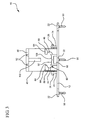
- FIG. 2 a cross-sectioned side view of the delivery system 10 is shown in an opened position.
- the aperture 34 of the base 12 is generally positioned adjacent to the catheter support 90, such that the support surface 92 ends into the aperture 34.
- a catheter 72 may be supported by the catheter support 90 and inserted directly into the aperture 34 without kinking or otherwise occluding the catheter 72.
- the walls of the aperture 34 are generally perpendicular to the base 12 so as to direct the inserted portion 78 of the catheter 72 into the target tissue 28 at a right angle.
- the aperture 32 is provided at an angle of less than 90°, such that the catheter 72 is inserted into the target tissue 28 at an angle of less than 90°.
- the support surface 92 of the catheter support 90 further includes a groove 100 to compatibly receive an outer surface of the uninserted portion 76 of the catheter 72.
- the groove 100 generally includes a recessed feature having a radius or contour configured to retain the catheter 72 on the support surface 90.
- the arched surface 48 of the clip 40 further comprises a groove 102 to compatibly receive an outer surface of the uninserted portion 76 of the catheter 72.
- the groove 102 generally includes a recessed feature having a radius or contoured configured to retain the catheter 72 in a desired position between the clip 40 and the catheter support 90.
- the grooves 100 and 102 are used in combination to further retain a desired position of the catheter 72 between the clip 40 and the catheter support 90.
- the support surface 92 of the catheter support 90 further comprises a tapered slope 106 that directs and guides the catheter 72 over the support surface 92 and into the aperture 34.
- the support surface 92 is funnel-shaped such that the tapered walls 107 of the support surface 92 direct the catheter 72 into the aperture 34.
- the base 12 of the delivery device 10 may further include features to promote stability to the mounted device 10. For example, in some embodiments lateral protrusions or wings 36 are provided to accommodate a fastener, as well as to provide lateral stability to the device 10. In other embodiments, forward and aft wings 54 and 56 are provided to further stabilize the mounted delivery device 10.
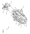
- FIG. 5 a perspective top view of the delivery device 10 is shown in an opened configuration following insertion of a catheter assembly 70.
- the catheter adapter 74 of the catheter assembly 70 is positioned and secured in the receiving channel 60.
- the position of the catheter 76 is maintained in the aperture 34 and in the target tissue 28.
- the position of the catheter adapter 74 within the channel 60 is maintained by an interaction between the plurality of tongues 66 (see Figure 4 ) of the channel 60 and the plurality of grooves 80 adjacent to the plurality of tongues 66 (see Figure 1 ).
- the interaction between the plurality of tongues 66 and the plurality of grooves 80 prevents the catheter adapter 74 from sliding within the channel 60.
- lip portions 84 of the opposing walls 64 overlap a portion of the upper surface 38 of the catheter adapter 74 to further retain the catheter adapter 74 within the channel 60.
- the upper surface 38 of the catheter adapter 74 includes a second plurality of grooves 108.
- the catheter adapter 74 may be rotated and positioned within the channel 60 such that the upper surface 38 of the catheter adapter 74 forms an interface with the plurality of tongues 66. As such, the position of the fluid inlet 88 may be adjusted as required by the physician.
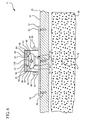
- FIG. 6 a cross-sectioned rear view of the delivery device 10 is shown in an opened configuration following insertion of a catheter assembly 70.
- Figure 6 clearly demonstrates the interaction between the catheter adapter 74 and the groove 68 or recessed feature of the opposing walls 64 and the lips 84. Additionally, the plurality of grooves 80 and the plurality of tongues 66 are clearly shown in a coupled configuration.
- the catheter adapter 74 comprises a plurality of tongues that adjustably couple with a plurality of grooves within the channel 60 to secure the position of the catheter adapter 74 within the channel 60.
- any adjustable coupling system may be used to position the catheter adapter 74 within the channel 60 so as to maintain a position of the catheter 72 within the target tissue 28.
- FIG. 7 a perspective top view of the delivery device 10 is shown in a closed position.
- the clip 40 of the device 10 has been moved to a closed position such that the ledge features 46 of the clip 40 have interlocked with the clip catch features 62 of the opposing walls 64.
- the catheter guards 52 have been repositioned to straddle a portion of the uninserted catheter 76.
- the positions of the catheter guards 52, the clip 40 and the catheter support 90 (not seen in this Figure) secure the position of the catheter 72 relative to the delivery device 10.
- the arched position of the catheter 72 and the horizontal position of the catheter adapter 74 provide a low profile delivery system 10.
- the trocar 110 generally comprises a semirigid wire 114 or stylet having a length that extends through an internal cavity of the catheter assembly 70.
- the trocar 110 further comprises a tip end 112 that extends beyond a tip portion 104 of the catheter 78.
- the tip end 112 is generally sharpened or tapered to facilitate movement of the tip end 112 and the tip portion 104 of the catheter through the target tissue 28.
- the trocar 110 and catheter 78 are inserted into the target tissue 28 until a desired insertion depth is attained.
- a mechanical device such as a micromanipulator 120 (shown in phantom) is coupled to the catheter adapter 74 to assist in placement of the catheter 78 and trocar 110 within the target tissue 28.
- the uninserted portion 76 of the catheter is arched over the support surface 92 of the catheter support 90 and the catheter adapter 74 is secured within the receiving channel 60.
- the clip 40 is then moved to a closed position, and the ledge features 46 interlock with the clip catches 62 of the opposing walls 64.
- the trocar 110 is then removed from the catheter assembly 70 thereby enabling infusion to the target tissue via the fluid inlet 88.
- the trocar 110 is removed prior to moving the clip 40 to a closed position.
- the clip 40 is moved to a closed position enabling infusion to the target tissue via the fluid inlet 88.
- multiple insertion depths are achieved with a single catheter assembly 70.
- a catheter assembly 70 having a catheter length is inserted into the target tissue to a first depth wherein the catheter adapter 74 is secured within the receiving channel 60 in a first position.
- the insertion depth of the catheter 72 is increased by repositioning the catheter adapter 74 within the receiving channel 60 to a second position.
- the insertion depth of the catheter 72 is decreased by reposition the catheter adapter 74 within the receiving channel 60 to a third position.
- the insertion depth of the catheter 78 is adjusted by providing a plurality of catheter assemblies, each assembly 70 having a catheter 72 comprising a different length.
- a catheter assembly 70 having a catheter 72 with a greater length is selected.
- a catheter assembly 70 having a catheter 72 with a lesser length is selected.
- the delivery system 10 may be modified to include a removable clip 40.
- Other design features may be further modified to optimize functionality of the system 10.
- base 12 is modified to include a slightly concave surface configured to more accurately interface with a non-planar surface, such as the surface of a patients scalp.
- delivery system 10 is modified to include additional structural features to provide support to the various functional features of the device, as shown.
Landscapes
- Health & Medical Sciences (AREA)
- Life Sciences & Earth Sciences (AREA)
- Biophysics (AREA)
- Pulmonology (AREA)
- Engineering & Computer Science (AREA)
- Anesthesiology (AREA)
- Biomedical Technology (AREA)
- Heart & Thoracic Surgery (AREA)
- Hematology (AREA)
- Animal Behavior & Ethology (AREA)
- General Health & Medical Sciences (AREA)
- Public Health (AREA)
- Veterinary Medicine (AREA)
- Media Introduction/Drainage Providing Device (AREA)
- Infusion, Injection, And Reservoir Apparatuses (AREA)
Claims (14)
- Katheterbefestigungsvorrichtung für die konvektionsverstärkte Verabreichung die intracranielle Verabreichung, mit:einer Basis (12) mit einer im Wesentlichen planaren Oberfläche zur Bildung einer Schnittstelle mit einem Patienten,wobei die Basis (12) an einer Außenfläche des Patienten mittels mehrerer Befestigungseinrichtungen befestigbar ist, so dass die Position des Katheters stabil bleibt, um eine effektive Verteilung eines Medikaments in einem Zielgewebe zu gewährleisten;einem Aufnahmekanal (60), der ein distales Ende der Basis bildet und derart konfiguriert ist, dass er einen Adapterbereich eines Katheters aufnimmt, wobei ein Bereich des Aufnahmekanals ferner eine Cliprasteinrichtung aufweist;einer Katheterstütze (90) mit einer ersten gewölbten Fläche und einer ersten Nut zur Aufnahme eines Rohrbereichs des Katheters;einer Öffnung (34), die proximal der Katheterstütze (90) angeordnet ist, wobei die Öffnung (34) einen Durchgang durch die Basis bildet, um den Durchtritt des Rohrbereichs des Katheters durch die Basis zu ermöglichen;einem Clip (40), der gelenkig mit einem proximalen Ende der Basis verbunden ist, wobei der Clip eine Innenfläche (44) und eine Außenfläche (42) aufweist, wobei die Innenfläche eine zweite gewölbte Fläche und eine zweite Nut zum Zurückhalten des Bereichs des Katheters gegen die erste gewölbte Fläche und die erste Nut aufweist, wobei die Außenfläche eine Leisteneinrichtung aufweist, um in kompatibler Weise mit dem Clipverschluss zusammenzugreifen, wobei der Clip eine Öffnungsposition und eine Schließposition aufweist.
- Vorrichtung nach Anspruch 1, ferner mit mehreren Nuten, welche einen Bereich des Aufnahmekanals bilden, wobei die mehreren Nuten derart konfiguriert sind, dass sie in kompatibler Weise mehrere Laschen aufnehmen, welche eine Außenfläche des Katheteradapters bilden, wobei eine Interaktion zwischen den mehreren Nuten und den mehreren Laschen eine Position des Katheteradapters in dem Aufnahmekanal sichert.
- Vorrichtung nach Anspruch 1, bei welcher eine Innenfläche des Aufnahmekanals derart ausgebildet ist, dass sie eine Außenfläche des Katheteradapters spiegelt, und wobei die Außenfläche des Katheteradapters in kompatibler Weise in der Innenfläche des Aufnahmekanals sitzt.
- Vorrichtung nach Anspruch 1, bei welcher die zweite Nut des Clips ferner zwei gegenüberliegende Katheterschutzeinrichtungen aufweist, welche einen Bereich des Katheters übergreifen, wenn sich der Clip in der Schließposition befindet.
- Vorrichtung nach Anspruch 1, bei welcher die Schließposition den Clipverschluss des Aufnahmekanals und die Leisteneinrichtung des Clips miteinander verriegelt.
- Vorrichtung nach Anspruch 1, bei welcher die Basis ferner mehrere Löcher (22) zum Aufnehmen mehrerer Befestigungseinrichtungen aufweist.
- Vorrichtung nach Anspruch 2, bei welcher die mehreren Laschen an mehreren Positionen einstellbar mit den mehreren Nuten zusammengreifen, wodurch der Katheteradapter wahlweise an den mehreren Positionen mit dem Aufnahmeelement der Vorrichtung gekoppelt ist.
- Vorrichtung nach Anspruch 7, bei welcher das selektive Koppeln des Katheteradapters an den mehreren Positionen die Einführtiefe eines Spitzenbereichs des Katheters in ein Zielgewebe regelt und bestimmt.
- Vorrichtung nach Anspruch 1, bei welcher der Aufnahmekanal einen horizontal positionierten Hohlraum zum Aufnehmen eines Adapterbereichs eines Katheters, wobei die Katheterstütze eine erste gewölbte Fläche zum Stützen eines nicht eingeführten Bereichs des Katheters in einer gebogenen Konfiguration aufweist.
- Vorrichtung nach Anspruch 9, ferner mit mehreren Nuten, die einen Bereich des horizontal positionieren Hohlraums bilden, wobei die mehreren Nuten derart konfiguriert sind, dass sie in kompatibler und austauschbarer Weise mehrere Laschen aufnehmen, die eine Außenfläche des Adapterbereichs des Katheters bilden, wobei eine Interaktion zwischen den mehreren Nuten und den mehreren Laschen einen Bereich des Katheteradapters in dem Aufnahmekanal sichert.
- Vorrichtung nach Anspruch 9, bei welcher eine Innenfläche des horizontal positionierten Hohlraums derart konfiguriert ist, dass sie eine Außenfläche des Katheteradapters spiegelt, und wobei die Außenfläche des Katheteradapters in kompatibler Weise in der Innenfläche des horizontal positionierten Hohlraums sitzt, um den Adapterbereich des Katheters in einer im Allgemeinen horizontalen Ausrichtung zu halten.
- Vorrichtung nach Anspruch 9, ferner mit einer ersten Katheternut, die einen Bereich der ersten gewölbten Fläche bildet, und einer zweiten Katheternut, die einen Bereich der zweiten gewölbte Fläche bildet, wobei die erste und die zweite Katheternut den nicht eingeführten Bereich des Katheters zwischen der Katheterstütze und dem Clip aufnehmen und halten, wenn sich der Clip in der Schließposition befindet.
- Vorrichtung nach Anspruch 9, bei welcher die Basis ferner mehrere Löcher zum Aufnehmen mehrerer Befestigungseinrichtungen (50) aufweist.
- Vorrichtung nach Anspruch 10, bei welcher die mehreren Laschen an mehreren Positionen einstellbar mit den mehreren Nuten zusammengreifen, wodurch der Adapterbereich des Katheters wahlweise an den mehreren Positionen mit dem Aufnahmeelement der Vorrichtung gekoppelt ist, um eine gewünschte Einführtiefe eines Spitzenbereichs des Katheters in das Zielgewebe beizubehalten.
Applications Claiming Priority (2)
| Application Number | Priority Date | Filing Date | Title |
|---|---|---|---|
| US14402309P | 2009-01-12 | 2009-01-12 | |
| PCT/US2010/020609 WO2010081067A1 (en) | 2009-01-12 | 2010-01-11 | Systems and methods for providing a convection-enhanced delivery device |
Publications (2)
| Publication Number | Publication Date |
|---|---|
| EP2376172A1 EP2376172A1 (de) | 2011-10-19 |
| EP2376172B1 true EP2376172B1 (de) | 2014-07-23 |
Family
ID=42154341
Family Applications (1)
| Application Number | Title | Priority Date | Filing Date |
|---|---|---|---|
| EP10700628.0A Not-in-force EP2376172B1 (de) | 2009-01-12 | 2010-01-11 | Systeme und verfahren für eine konvektionsverstärkte freisetzungsvorrichtung |
Country Status (4)
| Country | Link |
|---|---|
| US (1) | US9278193B2 (de) |
| EP (1) | EP2376172B1 (de) |
| ES (1) | ES2511046T3 (de) |
| WO (1) | WO2010081067A1 (de) |
Cited By (1)
| Publication number | Priority date | Publication date | Assignee | Title |
|---|---|---|---|---|
| EP4688079A4 (de) * | 2023-03-31 | 2026-07-08 | Forcast Orthopedics Inc | Tragbare medizinische vorrichtung |
Families Citing this family (6)
| Publication number | Priority date | Publication date | Assignee | Title |
|---|---|---|---|---|
| US11864884B2 (en) * | 2016-05-20 | 2024-01-09 | Brainlab Ag | Tracking reference fixation support |
| US10799312B2 (en) | 2017-04-28 | 2020-10-13 | Edwards Lifesciences Corporation | Medical device stabilizing apparatus and method of use |
| JP7134229B2 (ja) | 2017-07-06 | 2022-09-09 | ラグビア バスデ, | 組織把持デバイスおよび関連方法 |
| WO2019075095A1 (en) | 2017-10-10 | 2019-04-18 | Raghuveer Basude | FABRIC PREVENTION DEVICES AND ASSOCIATED METHODS |
| US11931525B2 (en) | 2018-10-04 | 2024-03-19 | Edwards Lifesciences Corporation | Stabilizer for a delivery system |
| JP2024100618A (ja) * | 2023-01-16 | 2024-07-26 | テルモ株式会社 | カテーテル保持具 |
Citations (1)
| Publication number | Priority date | Publication date | Assignee | Title |
|---|---|---|---|---|
| WO2008119041A1 (en) * | 2007-03-27 | 2008-10-02 | Cranial Medical Systems, Inc. | Anchoring apparatus and methods for use |
Family Cites Families (9)
| Publication number | Priority date | Publication date | Assignee | Title |
|---|---|---|---|---|
| US6827705B2 (en) * | 1993-03-19 | 2004-12-07 | Venetec International, Inc. | Catheter anchoring system |
| US5690616A (en) * | 1996-01-16 | 1997-11-25 | Mogg; Alan David | Catheter clamp |
| DE19749741C1 (de) * | 1997-11-11 | 1998-11-05 | Medi Globe Gip Medizin Technik | Fixiervorrichtung zur Befestigung eines percutan verlegten Schlauchs |
| US6572588B1 (en) * | 2000-03-10 | 2003-06-03 | Venetec International, Inc. | Medical anchoring system |
| GB0203713D0 (en) | 2002-02-16 | 2002-04-03 | Mogg Alan D | Catheter clamp |
| US20030199831A1 (en) * | 2002-04-23 | 2003-10-23 | Morris Mary M. | Catheter anchor system and method |
| NZ538214A (en) | 2002-08-15 | 2006-05-26 | Venetec Int Inc | Catheter securement device |
| US7963956B2 (en) | 2003-04-22 | 2011-06-21 | Antisense Pharma Gmbh | Portable equipment for administration of fluids into tissues and tumors by convection enhanced delivery technique |
| EP2060287B1 (de) | 2007-11-14 | 2011-06-15 | BrainLAB AG | Medikamentenzuführungssystem für CED (Convection Enhanced Delivery)-Katheterinfusionen |
-
2010
- 2010-01-11 US US13/143,535 patent/US9278193B2/en active Active
- 2010-01-11 WO PCT/US2010/020609 patent/WO2010081067A1/en not_active Ceased
- 2010-01-11 ES ES10700628.0T patent/ES2511046T3/es active Active
- 2010-01-11 EP EP10700628.0A patent/EP2376172B1/de not_active Not-in-force
Patent Citations (1)
| Publication number | Priority date | Publication date | Assignee | Title |
|---|---|---|---|---|
| WO2008119041A1 (en) * | 2007-03-27 | 2008-10-02 | Cranial Medical Systems, Inc. | Anchoring apparatus and methods for use |
Cited By (1)
| Publication number | Priority date | Publication date | Assignee | Title |
|---|---|---|---|---|
| EP4688079A4 (de) * | 2023-03-31 | 2026-07-08 | Forcast Orthopedics Inc | Tragbare medizinische vorrichtung |
Also Published As
| Publication number | Publication date |
|---|---|
| US9278193B2 (en) | 2016-03-08 |
| WO2010081067A1 (en) | 2010-07-15 |
| ES2511046T3 (es) | 2014-10-22 |
| EP2376172A1 (de) | 2011-10-19 |
| US20110306934A1 (en) | 2011-12-15 |
Similar Documents
| Publication | Publication Date | Title |
|---|---|---|
| US9278193B2 (en) | Systems and methods for providing a convection-enhanced delivery device | |
| KR0161328B1 (ko) | 결합된 척수-경막외 니이들의 길이를 조절하기위한 방법 및 장치 | |
| JP7012784B2 (ja) | 側部ポートの流体コネクタを持つ皮下注入セット | |
| JP6122021B2 (ja) | カテーテル位置決めシステム | |
| US8147480B2 (en) | Catheter for reduced reflux in targeted tissue delivery of a therapeutic agent | |
| US7211068B2 (en) | Infusion device having offset flow path | |
| ES2720158T3 (es) | Dispositivo de inserción para un conducto médico | |
| US20070106234A1 (en) | Infiltration cannula | |
| JP6356213B2 (ja) | 薬剤注入のための傾斜式挿入器 | |
| US12396750B2 (en) | Adjustable stepped cannula | |
| EP2385854B1 (de) | Optimierte intrakranielle katheter für konvektionsverstärkte verabreichung von therapeutika | |
| WO2008124123A1 (en) | Stabilized elongate implantable vascular access device | |
| JP2022087288A (ja) | 閉塞の低減を伴う医療用デバイス | |
| JP2022186913A (ja) | 医薬物を注入するための皮下注入装置 | |
| CN106039481A (zh) | 注入针单元、液体注入装置 | |
| US20230021353A1 (en) | Securing A Catheter Device | |
| WO2016138004A1 (en) | Injection needle having varying caliber | |
| WO2014128824A1 (ja) | 医療用器具 | |
| RU2463087C2 (ru) | Инъекционная площадка для впрыскивания лекарственных препаратов | |
| CN221513230U (zh) | 柔性导管系统和颅骨固定系统 | |
| US6468252B1 (en) | Clamp for vascular access device | |
| US20230372675A1 (en) | Vascular Access System With Integrated Catheter, Extension Set Providing Integrated Catheter Septum Access, Stabilization Features and Direct Probe Access | |
| RU2806631C2 (ru) | Предохранительный механизм для иглы губера в сборе | |
| HK40048812B (en) | Subcutaneous infusion device for injecting medicinal substances | |
| BR112020021351B1 (pt) | Sistema de cateter provido com instrumento remoto |
Legal Events
| Date | Code | Title | Description |
|---|---|---|---|
| PUAI | Public reference made under article 153(3) epc to a published international application that has entered the european phase |
Free format text: ORIGINAL CODE: 0009012 |
|
| 17P | Request for examination filed |
Effective date: 20110713 |
|
| AK | Designated contracting states |
Kind code of ref document: A1 Designated state(s): AT BE BG CH CY CZ DE DK EE ES FI FR GB GR HR HU IE IS IT LI LT LU LV MC MK MT NL NO PL PT RO SE SI SK SM TR |
|
| DAX | Request for extension of the european patent (deleted) | ||
| 17Q | First examination report despatched |
Effective date: 20120326 |
|
| GRAP | Despatch of communication of intention to grant a patent |
Free format text: ORIGINAL CODE: EPIDOSNIGR1 |
|
| INTG | Intention to grant announced |
Effective date: 20140204 |
|
| GRAS | Grant fee paid |
Free format text: ORIGINAL CODE: EPIDOSNIGR3 |
|
| GRAA | (expected) grant |
Free format text: ORIGINAL CODE: 0009210 |
|
| AK | Designated contracting states |
Kind code of ref document: B1 Designated state(s): AT BE BG CH CY CZ DE DK EE ES FI FR GB GR HR HU IE IS IT LI LT LU LV MC MK MT NL NO PL PT RO SE SI SK SM TR |
|
| REG | Reference to a national code |
Ref country code: GB Ref legal event code: FG4D |
|
| REG | Reference to a national code |
Ref country code: CH Ref legal event code: EP |
|
| REG | Reference to a national code |
Ref country code: IE Ref legal event code: FG4D |
|
| REG | Reference to a national code |
Ref country code: AT Ref legal event code: REF Ref document number: 678517 Country of ref document: AT Kind code of ref document: T Effective date: 20140815 |
|
| REG | Reference to a national code |
Ref country code: DE Ref legal event code: R096 Ref document number: 602010017678 Country of ref document: DE Effective date: 20140904 |
|
| REG | Reference to a national code |
Ref country code: ES Ref legal event code: FG2A Ref document number: 2511046 Country of ref document: ES Kind code of ref document: T3 Effective date: 20141022 |
|
| REG | Reference to a national code |
Ref country code: AT Ref legal event code: MK05 Ref document number: 678517 Country of ref document: AT Kind code of ref document: T Effective date: 20140723 |
|
| REG | Reference to a national code |
Ref country code: NL Ref legal event code: VDEP Effective date: 20140723 |
|
| REG | Reference to a national code |
Ref country code: LT Ref legal event code: MG4D |
|
| PG25 | Lapsed in a contracting state [announced via postgrant information from national office to epo] |
Ref country code: FI Free format text: LAPSE BECAUSE OF FAILURE TO SUBMIT A TRANSLATION OF THE DESCRIPTION OR TO PAY THE FEE WITHIN THE PRESCRIBED TIME-LIMIT Effective date: 20140723 Ref country code: SE Free format text: LAPSE BECAUSE OF FAILURE TO SUBMIT A TRANSLATION OF THE DESCRIPTION OR TO PAY THE FEE WITHIN THE PRESCRIBED TIME-LIMIT Effective date: 20140723 Ref country code: LT Free format text: LAPSE BECAUSE OF FAILURE TO SUBMIT A TRANSLATION OF THE DESCRIPTION OR TO PAY THE FEE WITHIN THE PRESCRIBED TIME-LIMIT Effective date: 20140723 Ref country code: NO Free format text: LAPSE BECAUSE OF FAILURE TO SUBMIT A TRANSLATION OF THE DESCRIPTION OR TO PAY THE FEE WITHIN THE PRESCRIBED TIME-LIMIT Effective date: 20141023 Ref country code: PT Free format text: LAPSE BECAUSE OF FAILURE TO SUBMIT A TRANSLATION OF THE DESCRIPTION OR TO PAY THE FEE WITHIN THE PRESCRIBED TIME-LIMIT Effective date: 20141124 Ref country code: BG Free format text: LAPSE BECAUSE OF FAILURE TO SUBMIT A TRANSLATION OF THE DESCRIPTION OR TO PAY THE FEE WITHIN THE PRESCRIBED TIME-LIMIT Effective date: 20141023 Ref country code: GR Free format text: LAPSE BECAUSE OF FAILURE TO SUBMIT A TRANSLATION OF THE DESCRIPTION OR TO PAY THE FEE WITHIN THE PRESCRIBED TIME-LIMIT Effective date: 20141024 |
|
| PG25 | Lapsed in a contracting state [announced via postgrant information from national office to epo] |
Ref country code: CY Free format text: LAPSE BECAUSE OF FAILURE TO SUBMIT A TRANSLATION OF THE DESCRIPTION OR TO PAY THE FEE WITHIN THE PRESCRIBED TIME-LIMIT Effective date: 20140723 Ref country code: HR Free format text: LAPSE BECAUSE OF FAILURE TO SUBMIT A TRANSLATION OF THE DESCRIPTION OR TO PAY THE FEE WITHIN THE PRESCRIBED TIME-LIMIT Effective date: 20140723 Ref country code: PL Free format text: LAPSE BECAUSE OF FAILURE TO SUBMIT A TRANSLATION OF THE DESCRIPTION OR TO PAY THE FEE WITHIN THE PRESCRIBED TIME-LIMIT Effective date: 20140723 Ref country code: LV Free format text: LAPSE BECAUSE OF FAILURE TO SUBMIT A TRANSLATION OF THE DESCRIPTION OR TO PAY THE FEE WITHIN THE PRESCRIBED TIME-LIMIT Effective date: 20140723 Ref country code: NL Free format text: LAPSE BECAUSE OF FAILURE TO SUBMIT A TRANSLATION OF THE DESCRIPTION OR TO PAY THE FEE WITHIN THE PRESCRIBED TIME-LIMIT Effective date: 20140723 Ref country code: IS Free format text: LAPSE BECAUSE OF FAILURE TO SUBMIT A TRANSLATION OF THE DESCRIPTION OR TO PAY THE FEE WITHIN THE PRESCRIBED TIME-LIMIT Effective date: 20141123 Ref country code: AT Free format text: LAPSE BECAUSE OF FAILURE TO SUBMIT A TRANSLATION OF THE DESCRIPTION OR TO PAY THE FEE WITHIN THE PRESCRIBED TIME-LIMIT Effective date: 20140723 |
|
| REG | Reference to a national code |
Ref country code: DE Ref legal event code: R097 Ref document number: 602010017678 Country of ref document: DE |
|
| PG25 | Lapsed in a contracting state [announced via postgrant information from national office to epo] |
Ref country code: RO Free format text: LAPSE BECAUSE OF FAILURE TO SUBMIT A TRANSLATION OF THE DESCRIPTION OR TO PAY THE FEE WITHIN THE PRESCRIBED TIME-LIMIT Effective date: 20140723 Ref country code: CZ Free format text: LAPSE BECAUSE OF FAILURE TO SUBMIT A TRANSLATION OF THE DESCRIPTION OR TO PAY THE FEE WITHIN THE PRESCRIBED TIME-LIMIT Effective date: 20140723 Ref country code: EE Free format text: LAPSE BECAUSE OF FAILURE TO SUBMIT A TRANSLATION OF THE DESCRIPTION OR TO PAY THE FEE WITHIN THE PRESCRIBED TIME-LIMIT Effective date: 20140723 Ref country code: DK Free format text: LAPSE BECAUSE OF FAILURE TO SUBMIT A TRANSLATION OF THE DESCRIPTION OR TO PAY THE FEE WITHIN THE PRESCRIBED TIME-LIMIT Effective date: 20140723 Ref country code: SK Free format text: LAPSE BECAUSE OF FAILURE TO SUBMIT A TRANSLATION OF THE DESCRIPTION OR TO PAY THE FEE WITHIN THE PRESCRIBED TIME-LIMIT Effective date: 20140723 |
|
| PLBE | No opposition filed within time limit |
Free format text: ORIGINAL CODE: 0009261 |
|
| STAA | Information on the status of an ep patent application or granted ep patent |
Free format text: STATUS: NO OPPOSITION FILED WITHIN TIME LIMIT |
|
| PG25 | Lapsed in a contracting state [announced via postgrant information from national office to epo] |
Ref country code: BE Free format text: LAPSE BECAUSE OF NON-PAYMENT OF DUE FEES Effective date: 20150131 |
|
| 26N | No opposition filed |
Effective date: 20150424 |
|
| REG | Reference to a national code |
Ref country code: CH Ref legal event code: PL |
|
| PG25 | Lapsed in a contracting state [announced via postgrant information from national office to epo] |
Ref country code: LU Free format text: LAPSE BECAUSE OF FAILURE TO SUBMIT A TRANSLATION OF THE DESCRIPTION OR TO PAY THE FEE WITHIN THE PRESCRIBED TIME-LIMIT Effective date: 20150111 |
|
| PG25 | Lapsed in a contracting state [announced via postgrant information from national office to epo] |
Ref country code: MC Free format text: LAPSE BECAUSE OF FAILURE TO SUBMIT A TRANSLATION OF THE DESCRIPTION OR TO PAY THE FEE WITHIN THE PRESCRIBED TIME-LIMIT Effective date: 20140723 |
|
| PG25 | Lapsed in a contracting state [announced via postgrant information from national office to epo] |
Ref country code: LI Free format text: LAPSE BECAUSE OF NON-PAYMENT OF DUE FEES Effective date: 20150131 Ref country code: CH Free format text: LAPSE BECAUSE OF NON-PAYMENT OF DUE FEES Effective date: 20150131 |
|
| REG | Reference to a national code |
Ref country code: IE Ref legal event code: MM4A |
|
| PG25 | Lapsed in a contracting state [announced via postgrant information from national office to epo] |
Ref country code: SI Free format text: LAPSE BECAUSE OF FAILURE TO SUBMIT A TRANSLATION OF THE DESCRIPTION OR TO PAY THE FEE WITHIN THE PRESCRIBED TIME-LIMIT Effective date: 20140723 |
|
| REG | Reference to a national code |
Ref country code: FR Ref legal event code: PLFP Year of fee payment: 7 |
|
| PG25 | Lapsed in a contracting state [announced via postgrant information from national office to epo] |
Ref country code: IE Free format text: LAPSE BECAUSE OF NON-PAYMENT OF DUE FEES Effective date: 20150111 |
|
| PG25 | Lapsed in a contracting state [announced via postgrant information from national office to epo] |
Ref country code: BE Free format text: LAPSE BECAUSE OF FAILURE TO SUBMIT A TRANSLATION OF THE DESCRIPTION OR TO PAY THE FEE WITHIN THE PRESCRIBED TIME-LIMIT Effective date: 20140723 |
|
| REG | Reference to a national code |
Ref country code: FR Ref legal event code: PLFP Year of fee payment: 8 |
|
| PG25 | Lapsed in a contracting state [announced via postgrant information from national office to epo] |
Ref country code: MT Free format text: LAPSE BECAUSE OF FAILURE TO SUBMIT A TRANSLATION OF THE DESCRIPTION OR TO PAY THE FEE WITHIN THE PRESCRIBED TIME-LIMIT Effective date: 20140723 |
|
| PG25 | Lapsed in a contracting state [announced via postgrant information from national office to epo] |
Ref country code: HU Free format text: LAPSE BECAUSE OF FAILURE TO SUBMIT A TRANSLATION OF THE DESCRIPTION OR TO PAY THE FEE WITHIN THE PRESCRIBED TIME-LIMIT; INVALID AB INITIO Effective date: 20100111 Ref country code: SM Free format text: LAPSE BECAUSE OF FAILURE TO SUBMIT A TRANSLATION OF THE DESCRIPTION OR TO PAY THE FEE WITHIN THE PRESCRIBED TIME-LIMIT Effective date: 20140723 |
|
| PG25 | Lapsed in a contracting state [announced via postgrant information from national office to epo] |
Ref country code: TR Free format text: LAPSE BECAUSE OF FAILURE TO SUBMIT A TRANSLATION OF THE DESCRIPTION OR TO PAY THE FEE WITHIN THE PRESCRIBED TIME-LIMIT Effective date: 20140723 |
|
| REG | Reference to a national code |
Ref country code: FR Ref legal event code: PLFP Year of fee payment: 9 |
|
| PG25 | Lapsed in a contracting state [announced via postgrant information from national office to epo] |
Ref country code: MK Free format text: LAPSE BECAUSE OF FAILURE TO SUBMIT A TRANSLATION OF THE DESCRIPTION OR TO PAY THE FEE WITHIN THE PRESCRIBED TIME-LIMIT Effective date: 20140723 |
|
| PGFP | Annual fee paid to national office [announced via postgrant information from national office to epo] |
Ref country code: FR Payment date: 20191219 Year of fee payment: 11 |
|
| PGFP | Annual fee paid to national office [announced via postgrant information from national office to epo] |
Ref country code: GB Payment date: 20191223 Year of fee payment: 11 Ref country code: IT Payment date: 20200102 Year of fee payment: 11 Ref country code: DE Payment date: 20191218 Year of fee payment: 11 Ref country code: ES Payment date: 20200203 Year of fee payment: 11 |
|
| REG | Reference to a national code |
Ref country code: DE Ref legal event code: R119 Ref document number: 602010017678 Country of ref document: DE |
|
| GBPC | Gb: european patent ceased through non-payment of renewal fee |
Effective date: 20210111 |
|
| PG25 | Lapsed in a contracting state [announced via postgrant information from national office to epo] |
Ref country code: FR Free format text: LAPSE BECAUSE OF NON-PAYMENT OF DUE FEES Effective date: 20210131 |
|
| PG25 | Lapsed in a contracting state [announced via postgrant information from national office to epo] |
Ref country code: DE Free format text: LAPSE BECAUSE OF NON-PAYMENT OF DUE FEES Effective date: 20210803 Ref country code: GB Free format text: LAPSE BECAUSE OF NON-PAYMENT OF DUE FEES Effective date: 20210111 |
|
| REG | Reference to a national code |
Ref country code: ES Ref legal event code: FD2A Effective date: 20220422 |
|
| PG25 | Lapsed in a contracting state [announced via postgrant information from national office to epo] |
Ref country code: IT Free format text: LAPSE BECAUSE OF NON-PAYMENT OF DUE FEES Effective date: 20210111 |
|
| PG25 | Lapsed in a contracting state [announced via postgrant information from national office to epo] |
Ref country code: ES Free format text: LAPSE BECAUSE OF NON-PAYMENT OF DUE FEES Effective date: 20210112 |