EP2375705B1 - Gehäuse für einen Sprecher einer drahtlosen Vorrichtung - Google Patents
Gehäuse für einen Sprecher einer drahtlosen Vorrichtung Download PDFInfo
- Publication number
- EP2375705B1 EP2375705B1 EP11153840A EP11153840A EP2375705B1 EP 2375705 B1 EP2375705 B1 EP 2375705B1 EP 11153840 A EP11153840 A EP 11153840A EP 11153840 A EP11153840 A EP 11153840A EP 2375705 B1 EP2375705 B1 EP 2375705B1
- Authority
- EP
- European Patent Office
- Prior art keywords
- wireless device
- speaker
- enclosure
- case
- volume
- Prior art date
- Legal status (The legal status is an assumption and is not a legal conclusion. Google has not performed a legal analysis and makes no representation as to the accuracy of the status listed.)
- Active
Links
Images




Classifications
-
- H—ELECTRICITY
- H04—ELECTRIC COMMUNICATION TECHNIQUE
- H04M—TELEPHONIC COMMUNICATION
- H04M1/00—Substation equipment, e.g. for use by subscribers
- H04M1/02—Constructional features of telephone sets
- H04M1/03—Constructional features of telephone transmitters or receivers, e.g. telephone hand-sets
- H04M1/035—Improving the acoustic characteristics by means of constructional features of the housing, e.g. ribs, walls, resonating chambers or cavities
-
- H—ELECTRICITY
- H04—ELECTRIC COMMUNICATION TECHNIQUE
- H04R—LOUDSPEAKERS, MICROPHONES, GRAMOPHONE PICK-UPS OR LIKE ACOUSTIC ELECTROMECHANICAL TRANSDUCERS; ELECTRIC HEARING AIDS; PUBLIC ADDRESS SYSTEMS
- H04R1/00—Details of transducers, loudspeakers or microphones
- H04R1/02—Casings; Cabinets ; Supports therefor; Mountings therein
- H04R1/025—Arrangements for fixing loudspeaker transducers, e.g. in a box, furniture
-
- H—ELECTRICITY
- H04—ELECTRIC COMMUNICATION TECHNIQUE
- H04M—TELEPHONIC COMMUNICATION
- H04M1/00—Substation equipment, e.g. for use by subscribers
- H04M1/02—Constructional features of telephone sets
- H04M1/0202—Portable telephone sets, e.g. cordless phones, mobile phones or bar type handsets
- H04M1/026—Details of the structure or mounting of specific components
- H04M1/0266—Details of the structure or mounting of specific components for a display module assembly
-
- H—ELECTRICITY
- H04—ELECTRIC COMMUNICATION TECHNIQUE
- H04R—LOUDSPEAKERS, MICROPHONES, GRAMOPHONE PICK-UPS OR LIKE ACOUSTIC ELECTROMECHANICAL TRANSDUCERS; ELECTRIC HEARING AIDS; PUBLIC ADDRESS SYSTEMS
- H04R1/00—Details of transducers, loudspeakers or microphones
- H04R1/20—Arrangements for obtaining desired frequency or directional characteristics
- H04R1/22—Arrangements for obtaining desired frequency or directional characteristics for obtaining desired frequency characteristic only
- H04R1/28—Transducer mountings or enclosures modified by provision of mechanical or acoustic impedances, e.g. resonator, damping means
- H04R1/2803—Transducer mountings or enclosures modified by provision of mechanical or acoustic impedances, e.g. resonator, damping means for loudspeaker transducers
-
- H—ELECTRICITY
- H04—ELECTRIC COMMUNICATION TECHNIQUE
- H04R—LOUDSPEAKERS, MICROPHONES, GRAMOPHONE PICK-UPS OR LIKE ACOUSTIC ELECTROMECHANICAL TRANSDUCERS; ELECTRIC HEARING AIDS; PUBLIC ADDRESS SYSTEMS
- H04R2499/00—Aspects covered by H04R or H04S not otherwise provided for in their subgroups
- H04R2499/10—General applications
- H04R2499/11—Transducers incorporated or for use in hand-held devices, e.g. mobile phones, PDA's, camera's
Definitions
- This application relates to the field of wireless devices, and more specifically, to an enclosure for a speaker of a wireless device.
- Wireless mobile communication devices include microprocessors, memory, soundcards, speakers, headphones, and run one or more software applications in addition to providing for voice communications. Examples of software applications used in these wireless devices include micro-browsers, address books, email clients, instant messaging (“IM”) clients, and wavetable instruments. Additionally, wireless devices have access to a plurality of services via the Internet. A wireless device may, for example, be used to browse web sites on the Internet, to transmit and receive graphics, and to execute streaming audio and/or video applications. Such wireless devices may operate on a cellular network, on a wireless local area network (“WLAN”), or on both of these types of networks.
- WLAN wireless local area network
- British Patent specification no. 2,386,281 discloses an aural interface which comprises a transparent acoustic chamber superimposed on the display of a portable communications terminal.
- the present teaching relates to a wireless device as detailed in claim 1.
- Advantageous embodiments are detailed in the dependent claims.
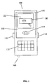
- FIG. 1 is a front view illustrating a wireless device in accordance with an embodiment of the application
- FIG 2 is a block diagram illustrating the wireless device of FIG. 1 ;
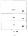
- FIG. 3 is a block diagram illustrating a memory of the wireless device of FIG. 1 ;
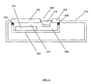
- FIG. 4 is a simplified longitudinal section view illustrating an enclosure for a speaker of the wireless device of FIG. 1 ;
- FIG. 5 is a simplified longitudinal section view illustrating an enclosure for a speaker of a wireless device in accordance with an alternate embodiment
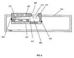
- FIG. 6 is a simplified longitudinal section view illustrating an enclosure for a speaker of a wireless device in accordance with an alternate embodiment
- FIG. 7 is a simplified longitudinal section view illustrating an enclosure for a speaker of a wireless device in accordance with an alternate embodiment.
- FIG. 8 is a simplified longitudinal section view illustrating an enclosure for a speaker of a wireless device in accordance with an alternate embodiment.
- FIG. 1 is a front view illustrating a wireless device 100 in accordance with an embodiment of the application.
- the wireless device 100 includes a case 150, a display (e.g., a liquid crystal display (“LCD”)) 122, a graphical user interface ("GUI") 180 displayed on the display 122, a transparent cover (e.g., a lens) 105 mounted over the display 122 for protection thereof, a speaker 134, a keyboard (or keypad) 132, a thumbwheel (or trackwheel) 110, various select buttons 120, and various inputs/outputs (e.g., power connector jack, data interface ports, headphones jack, etc.) 160.
- the wireless device 100 typically includes one or more circuit boards (not shown in FIG.
- FIG. 2 is a block diagram illustrating the wireless device 100 of FIG. 1 .
- the wireless device 100 may operate over a wireless network 220.
- the wireless network 220 may include antenna, base stations, access points, transceivers, supporting radio equipment, etc., as known to those of ordinary skill in the art, for supporting wireless communications between the wireless device 100 and other devices (not shown).
- the wireless device 100 may be a two-way communication device having at least voice and advanced data communication capabilities, including the capability to communicate with other devices. Depending on the functionality provided by the device 100, it may be referred to as a data messaging device, a two-way pager, a cellular telephone with data messaging capabilities, a wireless Internet appliance, a data communication device (with or without telephony capabilities), a Wi-Fi device, a WLAN device, a dual-mode (i.e., Wi-Fi and cellular) device, or a portable audio device.
- the device 100 may communicate with any one of a plurality of transceiver stations (not shown) within its geographic coverage area.
- the wireless device 100 has a communication subsystem 111, which includes a RF receiver, a RF transmitter, and associated components, such as one or more antenna elements (e.g., embedded or internal), local oscillators ("LOs”), and a processing module such as a digital signal processor (“DSP”) (all not shown).
- a communication subsystem 111 which includes a RF receiver, a RF transmitter, and associated components, such as one or more antenna elements (e.g., embedded or internal), local oscillators (“LOs”), and a processing module such as a digital signal processor (“DSP”) (all not shown).
- LOs local oscillators
- DSP digital signal processor
- the device 100 may be capable of cellular network access and hence the device 100 may have a subscriber identity module (or "SIM” card) 162 for inserting into a SIM interface (“IF") 164 in order to operate on the cellular network (e.g., a global system for mobile communication (“GSM”) network).
- SIM subscriber identity module
- IF SIM interface
- GSM global system for mobile communication
- the device 100 may be a battery-powered device and so it may also include a battery IF 154 for receiving one or more rechargeable batteries 156.
- the battery (or batteries) 156 provides electrical power to most if not all electrical circuitry in the device 100, and the battery IF 154 provides for a mechanical and electrical connection for it.
- the battery IF 154 is coupled to a regulator (not shown) which provides regulated power to the circuitry of the device 100.
- the wireless device 100 includes a microprocessor 138 which controls overall operation of the device 100. Communication functions, including at least data and voice communications, are performed through the communication subsystem 111.
- the microprocessor 138 also interacts with additional device subsystems such as the display 122, a flash memory 124 or other persistent store, a random access memory (“RAM”) 126, auxiliary input/output (“I/O") subsystems 128, a serial port (e.g., a universal serial bus (“USB”) port) 131, the keyboard 132, the clickable thumbwheel 110, the speaker 134, a microphone 136, a short-range communications subsystem 141, and other device subsystems 142.
- additional device subsystems such as the display 122, a flash memory 124 or other persistent store, a random access memory (“RAM”) 126, auxiliary input/output (“I/O") subsystems 128, a serial port (e.g., a universal serial bus (“USB”) port) 131, the keyboard 132, the click
- the microprocessor 138 in addition to its operating system functions, preferably enables execution of software applications on the device 100.
- a preferred application that may be loaded onto the device 100 may be a personal information manager (“PIM”) application having the ability to organize and manage data items relating to the user such as, but not limited to, instant messaging (“IM”), email, calendar events, voice mails, appointments, and task items.
- PIM personal information manager
- IM instant messaging
- SIM 162 one or more memory stores are available on the device 100 and SIM 162 to facilitate storage of PIM data items and other information.
- a received signal such as a text message, an email message, or web page download will be processed by the communication subsystem 111 and input to the microprocessor 138.
- the microprocessor 138 will preferably further process the signal for output to the display 122 and/or to the auxiliary I/O device 128.
- a user of the wireless device 100 may also compose data items, such as email messages, for example, using the keyboard 132 in conjunction with the display 122, and possibly the auxiliary I/O device 128.
- the keyboard 132 is preferably a complete alphanumeric keyboard and/or a telephone-type keypad. These composed items may be transmitted over a communication network 220 through the communication subsystem 111 or the short range communication subsystem 141.
- the overall operation of the wireless device 100 is substantially similar, except that the received signals would be output to the speaker 134 and signals for transmission would be generated by the microphone 136.
- Alternative voice or audio I/O subsystems such as a voice message recording subsystem, may also be implemented on the device 100.
- voice or audio signal output is preferably accomplished primarily through the speaker 134, the display 122 may also be used to provide, for example, an indication of the identity of a calling party, duration of a voice call, or other voice call related information.
- FIG. 3 is a block diagram illustrating a memory 200 of the wireless device 100 of FIG. 1 .
- the microprocessor 138 is coupled to the memory 200.
- the memory 200 has various hardware and software components for storing information (e.g., instructions, data, database tables, test parameters, etc.) for enabling operation of the device 100 and may include flash memory 124, RAM 126, ROM (not shown), disk drives (not shown), etc.
- the memory 200 may include a variety of storage devices typically arranged in a hierarchy of storage as understood to those skilled in the art.
- the wireless device 100 may be a multi-tasking wireless communications device configured for sending and receiving data items and for making and receiving voice calls.
- the microprocessor 138 of the wireless device 100 is typically coupled to one or more devices or subsystems (e.g., 110, 120, 132) for receiving user commands or queries and for displaying the results of these commands or queries to the user on the display 122.
- operating system (“O/S") software modules 202 resident on the device 100 provide a basic set of operations for supporting various applications typically operable through the GUI 180 and supporting GUI software modules 204.
- the present application provides an enclosure for the speaker 134 that allows the wireless device 100 to maintain its thickness while using a cavity that is not used for anything else in the wireless device 100. In addition, there is no need for separate sealing of this cavity as dust sealing of this cavity is already provided.
- FIG. 4 is a simplified longitudinal section view illustrating an enclosure 400 for a speaker 134 of the wireless device 100 of FIG. 1 .
- the enclosure 400 provides a back-volume 410 or cavity for the speaker 134 of the wireless device 100.
- the enclosure 400 is formed by the lower surface of the transparent cover 105, also called a lens, the upper surface of the display 122, and sealing material 420 that forms or completes the walls of the enclosure 400.
- the lens 105 is spaced apart from the display 122 by the sealing material 420 to form the back-volume 410 therebetween.
- Portions of the enclosure 400 may be formed by various supports 430 for the display 122 and/or speaker 132 (e.g., printed circuit boards, spacers, baffles, etc.) and by various portions of the case 150 depending on the geometry of the display 122, transparent cover 105, speaker 134, and case 150.
- the speaker 134 may form or complete a wall of the enclosure 400.
- the sealing material 420 may include dust sealing material that is typically used to seal the perimeter of the display 122 and transparent cover 105 to prevent dust from entering therebetween.
- the sealing material 420 may include acoustic sealing material to improve the performance of the back-volume 410.
- the material chosen for the sealing material 420 may include both appropriate dust sealing and acoustic sealing properties.
- the sealing material 420 may be silicon or a thermoplastic elastomer ("TPE").
- the speaker 134 is mounted proximate to the back-volume 410, and may become part of the enclosure 400.
- the speaker 134 is shown as being mounted behind the transparent cover 105 for projecting sound through an appropriate opening or openings 440 in the transparent cover 105.
- the speaker 134 may be mounted in the case 150 proximate to the back-volume 410 (see FIGS. 7-9 ).
- the speaker 134 is a magnetic type loudspeaker (i.e., having a magnet, cone, frame, etc.).
- the wireless device 100 has two or more speakers 134.
- FIG. 5 is a simplified longitudinal section view illustrating an enclosure 400 for a speaker 134 of a wireless device 100 in accordance with an alternate embodiment.
- the transparent cover 105 is L-shaped having one end proximate to one end of the display 122.
- the sealing material 420 does not necessarily form a significant portion of the enclosure 400.
- FIG. 6 is a simplified longitudinal section view illustrating an enclosure 400 for a speaker 134 of a wireless device 100 in accordance with an alternate embodiment.
- the transparent cover 105 is tapered at one end proximate to one end of the display 122.
- the sealing material 420 does not necessarily form a significant portion of the enclosure 400.
- FIG. 7 is a simplified longitudinal section view illustrating an enclosure 400 for a speaker 134 of a wireless device 100 in accordance with an alternate embodiment.
- the transparent cover 105 is L-shaped having one end proximate to one end of the display 122.
- the sealing material 420 does necessarily not form a significant portion of the enclosure 400.
- the speaker 134 is mounted on the back of the case 150 to which the back-volume 410 extends.
- FIG. 8 is a simplified longitudinal section view illustrating an enclosure 400 for a speaker 134 of a wireless device 100 in accordance with an alternate embodiment.
- the support 430 is C-shaped having one end proximate to the case 150.
- the sealing material 430 between the transparent cover 105 and the support 430 forms a portion of the enclosure 400 but the sealing material 430 between the support 430 and the case 150 does not necessarily form a significant portion of the enclosure 400.
- an opening or openings 440 for the speaker 134 is provided in the case 150 rather than in the transparent cover 105.
- the above embodiments may provide one or more advantages.
Landscapes
- Physics & Mathematics (AREA)
- Acoustics & Sound (AREA)
- Engineering & Computer Science (AREA)
- Signal Processing (AREA)
- Details Of Audible-Bandwidth Transducers (AREA)
- Telephone Set Structure (AREA)
- Structure Of Receivers (AREA)
- Fittings On The Vehicle Exterior For Carrying Loads, And Devices For Holding Or Mounting Articles (AREA)
Claims (11)
- Drahtlose Vorrichtung (100), die aufweist:einen magnetischen Lautsprecher (134);eine Anzeige (122), die in einem Gehäuse (150) angebracht ist; undeine transparente Abdeckung (105), die über der Anzeige (122) angebracht ist;wobei die Anzeige (122) zumindest teilweise von der transparenten Abdeckung (105) beabstandet ist, um zumindest einen Teil eines umschlossenen rückwärtigen Volumens (410) zu bilden, das in dem Gehäuse (150) für den magnetischen Lautsprecher (134) gebildet wird, wobei der magnetische Lautsprecher (134) direkt in dem umschlossenen rückwärtigen Volumen (410) angebracht ist;wobei die transparente Abdeckung (105) in einem ersten Teil des Gehäuses (150) angebracht ist; undwobei eine Öffnung (440) in einem zweiten Teil des Gehäuses (150) ausgebildet ist zum Aussenden von Klang von dem magnetischen Lautsprecher (134).
- Die drahtlose Vorrichtung (100) gemäß Anspruch 1, wobei der magnetische Lautsprecher (134) unter dem zweiten Teil des Gehäuses (150) angebracht ist und Klang durch die Öffnung (440) aussendet.
- Die drahtlose Vorrichtung (100) gemäß Anspruch 1 oder Anspruch 2, wobei der erste Teil und der zweite Teil auf gegenüberliegenden Oberflächen des Gehäuses (150) sind.
- Die drahtlose Vorrichtung (100) gemäß einem der Ansprüche 1 bis 3, wobei der erste Teil und der zweite Teil eine Vorderseite beziehungsweise eine Rückseite des Gehäuses (150) sind.
- Die drahtlose Vorrichtung (100) gemäß einem der Ansprüche 1 bis 4, wobei sich das umschlossene rückwärtige Volumen (410) zwischen den ersten und zweiten Teil des Gehäuses (150) erstreckt.
- Die drahtlose Vorrichtung (100) gemäß einem der Ansprüche 1 bis 5, wobei ein Teil des Gehäuses (150) das umschlossene rückwärtige Volumen (410) definiert.
- Die drahtlose Vorrichtung (100) gemäß einem der Ansprüche 1 bis 6, wobei zumindest eines der Anzeige (122) und des Lautsprechers (134) auf einem Träger (430) in der drahtlosen Vorrichtung (100) angebracht ist.
- Die drahtlose Vorrichtung (100) gemäß Anspruch 7, wobei der Träger (430) eine Leiterplatte aufweist.
- Die drahtlose Vorrichtung (100) gemäß einem der Ansprüche 1 bis 8, wobei ein Teil eines Dichtungsmaterials (420) das umschlossene rückwärtige Volumen (410) definiert.
- Die drahtlose Vorrichtung (100) gemäß Anspruch 9, wobei sich der Teil des Dichtungsmaterials (420) in der Nähe einer unteren Oberfläche der transparenten Abdeckung (105) befindet.
- Die drahtlose Vorrichtung (100) gemäß Anspruch 9 oder Anspruch 10, wobei das Dichtungsmaterial (420) zumindest eines aus einem Staubabdichtungs- und einem akustisch abdichtenden Material ist.
Applications Claiming Priority (1)
| Application Number | Priority Date | Filing Date | Title |
|---|---|---|---|
| EP09154049A EP2224695B1 (de) | 2009-02-27 | 2009-02-27 | Gehäuse für einen Sprecher einer drahtlosen Vorrichtung |
Related Parent Applications (1)
| Application Number | Title | Priority Date | Filing Date |
|---|---|---|---|
| EP09154049.2 Division | 2009-02-27 |
Publications (2)
| Publication Number | Publication Date |
|---|---|
| EP2375705A1 EP2375705A1 (de) | 2011-10-12 |
| EP2375705B1 true EP2375705B1 (de) | 2013-01-23 |
Family
ID=40728702
Family Applications (2)
| Application Number | Title | Priority Date | Filing Date |
|---|---|---|---|
| EP11153840A Active EP2375705B1 (de) | 2009-02-27 | 2009-02-27 | Gehäuse für einen Sprecher einer drahtlosen Vorrichtung |
| EP09154049A Active EP2224695B1 (de) | 2009-02-27 | 2009-02-27 | Gehäuse für einen Sprecher einer drahtlosen Vorrichtung |
Family Applications After (1)
| Application Number | Title | Priority Date | Filing Date |
|---|---|---|---|
| EP09154049A Active EP2224695B1 (de) | 2009-02-27 | 2009-02-27 | Gehäuse für einen Sprecher einer drahtlosen Vorrichtung |
Country Status (4)
| Country | Link |
|---|---|
| EP (2) | EP2375705B1 (de) |
| AT (1) | ATE505899T1 (de) |
| CA (1) | CA2691312C (de) |
| DE (1) | DE602009001096D1 (de) |
Families Citing this family (1)
| Publication number | Priority date | Publication date | Assignee | Title |
|---|---|---|---|---|
| WO2016040745A1 (en) * | 2014-09-12 | 2016-03-17 | Commscope Technologies Llc | Aesthetically appealing communications equipment enclosure |
Family Cites Families (4)
| Publication number | Priority date | Publication date | Assignee | Title |
|---|---|---|---|---|
| GB2374236B (en) | 2001-04-02 | 2004-09-01 | Ericsson Telefon Ab L M | Communications Apparatus |
| GB2386281B (en) * | 2002-03-07 | 2005-03-16 | Matsushita Comm Ind Uk Ltd | Aural interface for portable communications terminals |
| EP1603308B1 (de) * | 2004-06-01 | 2006-11-22 | Research In Motion Limited | Deckel für eine Anzeige eines Kommunikationsgerätes |
| KR100811871B1 (ko) | 2006-11-18 | 2008-03-10 | 주식회사 이엠텍 | 인클로져 음향변환장치 |
-
2009
- 2009-02-27 EP EP11153840A patent/EP2375705B1/de active Active
- 2009-02-27 EP EP09154049A patent/EP2224695B1/de active Active
- 2009-02-27 DE DE602009001096T patent/DE602009001096D1/de active Active
- 2009-02-27 AT AT09154049T patent/ATE505899T1/de not_active IP Right Cessation
-
2010
- 2010-01-28 CA CA2691312A patent/CA2691312C/en active Active
Also Published As
| Publication number | Publication date |
|---|---|
| CA2691312C (en) | 2014-08-19 |
| DE602009001096D1 (de) | 2011-05-26 |
| ATE505899T1 (de) | 2011-04-15 |
| EP2375705A1 (de) | 2011-10-12 |
| EP2224695B1 (de) | 2011-04-13 |
| EP2224695A1 (de) | 2010-09-01 |
| CA2691312A1 (en) | 2010-08-27 |
Similar Documents
| Publication | Publication Date | Title |
|---|---|---|
| US8483422B2 (en) | Enclosure for a speaker of a wireless device | |
| US8005207B2 (en) | Microphone coupler system for a communication device | |
| US7123736B2 (en) | Double-resonator micro-speaker assemblies and methods for tuning the same | |
| WO2007083442A1 (ja) | 携帯端末及びスピーカ | |
| CN216700057U (zh) | 电子设备 | |
| CN101473292A (zh) | 具有三维音频系统的无线通信装置 | |
| US8116504B2 (en) | Electronic device having a receiver | |
| CN111988701A (zh) | 一种终端设备 | |
| US7668320B2 (en) | Sound reproduction in portable electronic equipment | |
| JP2003319039A (ja) | 電子機器 | |
| CN102204275A (zh) | 包括垂直安装的扩音器的电子设备以及相关组件和方法 | |
| CN221177918U (zh) | 发声模组和电子设备 | |
| CA2691312C (en) | Enclosure for a speaker of a wireless device | |
| KR20060032195A (ko) | 폴더 단말기용 스피커 장치 | |
| US8459403B2 (en) | Front resonator for a speaker of a wireless device | |
| JP5515672B2 (ja) | 携帯端末 | |
| EP1780989A1 (de) | Mikrofonkoppler für ein Kommunikationsgerät | |
| EP2288177B1 (de) | Frontresonator für einen Lautsprecher einer drahtlosen Vorrichtung | |
| KR200341095Y1 (ko) | 멀티미디어 서비스 처리부를 포함하는 무선단말기용표시장치 모듈 | |
| CN107911963A (zh) | 电子设备的壳体组件及电子设备 |
Legal Events
| Date | Code | Title | Description |
|---|---|---|---|
| PUAI | Public reference made under article 153(3) epc to a published international application that has entered the european phase |
Free format text: ORIGINAL CODE: 0009012 |
|
| 17P | Request for examination filed |
Effective date: 20110209 |
|
| AC | Divisional application: reference to earlier application |
Ref document number: 2224695 Country of ref document: EP Kind code of ref document: P |
|
| AK | Designated contracting states |
Kind code of ref document: A1 Designated state(s): AT BE BG CH CY CZ DE DK EE ES FI FR GB GR HR HU IE IS IT LI LT LU LV MC MK MT NL NO PL PT RO SE SI SK TR |
|
| 17Q | First examination report despatched |
Effective date: 20120308 |
|
| GRAP | Despatch of communication of intention to grant a patent |
Free format text: ORIGINAL CODE: EPIDOSNIGR1 |
|
| GRAC | Information related to communication of intention to grant a patent modified |
Free format text: ORIGINAL CODE: EPIDOSCIGR1 |
|
| RIC1 | Information provided on ipc code assigned before grant |
Ipc: H04R 1/02 20060101ALI20120712BHEP Ipc: H04M 1/03 20060101AFI20120712BHEP |
|
| GRAS | Grant fee paid |
Free format text: ORIGINAL CODE: EPIDOSNIGR3 |
|
| GRAA | (expected) grant |
Free format text: ORIGINAL CODE: 0009210 |
|
| AC | Divisional application: reference to earlier application |
Ref document number: 2224695 Country of ref document: EP Kind code of ref document: P |
|
| AK | Designated contracting states |
Kind code of ref document: B1 Designated state(s): AT BE BG CH CY CZ DE DK EE ES FI FR GB GR HR HU IE IS IT LI LT LU LV MC MK MT NL NO PL PT RO SE SI SK TR |
|
| REG | Reference to a national code |
Ref country code: GB Ref legal event code: FG4D |
|
| REG | Reference to a national code |
Ref country code: CH Ref legal event code: EP |
|
| REG | Reference to a national code |
Ref country code: AT Ref legal event code: REF Ref document number: 595470 Country of ref document: AT Kind code of ref document: T Effective date: 20130215 Ref country code: CH Ref legal event code: EP |
|
| REG | Reference to a national code |
Ref country code: IE Ref legal event code: FG4D |
|
| REG | Reference to a national code |
Ref country code: DE Ref legal event code: R096 Ref document number: 602009013107 Country of ref document: DE Effective date: 20130321 |
|
| REG | Reference to a national code |
Ref country code: NL Ref legal event code: T3 |
|
| REG | Reference to a national code |
Ref country code: AT Ref legal event code: MK05 Ref document number: 595470 Country of ref document: AT Kind code of ref document: T Effective date: 20130123 |
|
| REG | Reference to a national code |
Ref country code: LT Ref legal event code: MG4D |
|
| PG25 | Lapsed in a contracting state [announced via postgrant information from national office to epo] |
Ref country code: SE Free format text: LAPSE BECAUSE OF FAILURE TO SUBMIT A TRANSLATION OF THE DESCRIPTION OR TO PAY THE FEE WITHIN THE PRESCRIBED TIME-LIMIT Effective date: 20130123 Ref country code: IS Free format text: LAPSE BECAUSE OF FAILURE TO SUBMIT A TRANSLATION OF THE DESCRIPTION OR TO PAY THE FEE WITHIN THE PRESCRIBED TIME-LIMIT Effective date: 20130523 Ref country code: LT Free format text: LAPSE BECAUSE OF FAILURE TO SUBMIT A TRANSLATION OF THE DESCRIPTION OR TO PAY THE FEE WITHIN THE PRESCRIBED TIME-LIMIT Effective date: 20130123 Ref country code: BE Free format text: LAPSE BECAUSE OF FAILURE TO SUBMIT A TRANSLATION OF THE DESCRIPTION OR TO PAY THE FEE WITHIN THE PRESCRIBED TIME-LIMIT Effective date: 20130123 Ref country code: NO Free format text: LAPSE BECAUSE OF FAILURE TO SUBMIT A TRANSLATION OF THE DESCRIPTION OR TO PAY THE FEE WITHIN THE PRESCRIBED TIME-LIMIT Effective date: 20130423 Ref country code: AT Free format text: LAPSE BECAUSE OF FAILURE TO SUBMIT A TRANSLATION OF THE DESCRIPTION OR TO PAY THE FEE WITHIN THE PRESCRIBED TIME-LIMIT Effective date: 20130123 Ref country code: ES Free format text: LAPSE BECAUSE OF FAILURE TO SUBMIT A TRANSLATION OF THE DESCRIPTION OR TO PAY THE FEE WITHIN THE PRESCRIBED TIME-LIMIT Effective date: 20130504 Ref country code: BG Free format text: LAPSE BECAUSE OF FAILURE TO SUBMIT A TRANSLATION OF THE DESCRIPTION OR TO PAY THE FEE WITHIN THE PRESCRIBED TIME-LIMIT Effective date: 20130423 |
|
| REG | Reference to a national code |
Ref country code: CH Ref legal event code: PFA Owner name: BLACKBERRY LIMITED, CA Free format text: FORMER OWNER: RESEARCH IN MOTION LIMITED, CA |
|
| PG25 | Lapsed in a contracting state [announced via postgrant information from national office to epo] |
Ref country code: FI Free format text: LAPSE BECAUSE OF FAILURE TO SUBMIT A TRANSLATION OF THE DESCRIPTION OR TO PAY THE FEE WITHIN THE PRESCRIBED TIME-LIMIT Effective date: 20130123 Ref country code: SI Free format text: LAPSE BECAUSE OF FAILURE TO SUBMIT A TRANSLATION OF THE DESCRIPTION OR TO PAY THE FEE WITHIN THE PRESCRIBED TIME-LIMIT Effective date: 20130123 Ref country code: PT Free format text: LAPSE BECAUSE OF FAILURE TO SUBMIT A TRANSLATION OF THE DESCRIPTION OR TO PAY THE FEE WITHIN THE PRESCRIBED TIME-LIMIT Effective date: 20130523 Ref country code: PL Free format text: LAPSE BECAUSE OF FAILURE TO SUBMIT A TRANSLATION OF THE DESCRIPTION OR TO PAY THE FEE WITHIN THE PRESCRIBED TIME-LIMIT Effective date: 20130123 Ref country code: GR Free format text: LAPSE BECAUSE OF FAILURE TO SUBMIT A TRANSLATION OF THE DESCRIPTION OR TO PAY THE FEE WITHIN THE PRESCRIBED TIME-LIMIT Effective date: 20130424 Ref country code: LV Free format text: LAPSE BECAUSE OF FAILURE TO SUBMIT A TRANSLATION OF THE DESCRIPTION OR TO PAY THE FEE WITHIN THE PRESCRIBED TIME-LIMIT Effective date: 20130123 |
|
| RAP2 | Party data changed (patent owner data changed or rights of a patent transferred) |
Owner name: BLACKBERRY LIMITED |
|
| PG25 | Lapsed in a contracting state [announced via postgrant information from national office to epo] |
Ref country code: HR Free format text: LAPSE BECAUSE OF FAILURE TO SUBMIT A TRANSLATION OF THE DESCRIPTION OR TO PAY THE FEE WITHIN THE PRESCRIBED TIME-LIMIT Effective date: 20130123 Ref country code: MC Free format text: LAPSE BECAUSE OF NON-PAYMENT OF DUE FEES Effective date: 20130228 |
|
| REG | Reference to a national code |
Ref country code: CH Ref legal event code: PL |
|
| PG25 | Lapsed in a contracting state [announced via postgrant information from national office to epo] |
Ref country code: SK Free format text: LAPSE BECAUSE OF FAILURE TO SUBMIT A TRANSLATION OF THE DESCRIPTION OR TO PAY THE FEE WITHIN THE PRESCRIBED TIME-LIMIT Effective date: 20130123 Ref country code: RO Free format text: LAPSE BECAUSE OF FAILURE TO SUBMIT A TRANSLATION OF THE DESCRIPTION OR TO PAY THE FEE WITHIN THE PRESCRIBED TIME-LIMIT Effective date: 20130123 Ref country code: CZ Free format text: LAPSE BECAUSE OF FAILURE TO SUBMIT A TRANSLATION OF THE DESCRIPTION OR TO PAY THE FEE WITHIN THE PRESCRIBED TIME-LIMIT Effective date: 20130123 Ref country code: CH Free format text: LAPSE BECAUSE OF NON-PAYMENT OF DUE FEES Effective date: 20130228 Ref country code: DK Free format text: LAPSE BECAUSE OF FAILURE TO SUBMIT A TRANSLATION OF THE DESCRIPTION OR TO PAY THE FEE WITHIN THE PRESCRIBED TIME-LIMIT Effective date: 20130123 Ref country code: LI Free format text: LAPSE BECAUSE OF NON-PAYMENT OF DUE FEES Effective date: 20130228 Ref country code: EE Free format text: LAPSE BECAUSE OF FAILURE TO SUBMIT A TRANSLATION OF THE DESCRIPTION OR TO PAY THE FEE WITHIN THE PRESCRIBED TIME-LIMIT Effective date: 20130123 |
|
| RAP2 | Party data changed (patent owner data changed or rights of a patent transferred) |
Owner name: BLACKBERRY LIMITED |
|
| PG25 | Lapsed in a contracting state [announced via postgrant information from national office to epo] |
Ref country code: CY Free format text: LAPSE BECAUSE OF FAILURE TO SUBMIT A TRANSLATION OF THE DESCRIPTION OR TO PAY THE FEE WITHIN THE PRESCRIBED TIME-LIMIT Effective date: 20130123 |
|
| PLBE | No opposition filed within time limit |
Free format text: ORIGINAL CODE: 0009261 |
|
| STAA | Information on the status of an ep patent application or granted ep patent |
Free format text: STATUS: NO OPPOSITION FILED WITHIN TIME LIMIT |
|
| REG | Reference to a national code |
Ref country code: IE Ref legal event code: MM4A |
|
| PG25 | Lapsed in a contracting state [announced via postgrant information from national office to epo] |
Ref country code: IT Free format text: LAPSE BECAUSE OF FAILURE TO SUBMIT A TRANSLATION OF THE DESCRIPTION OR TO PAY THE FEE WITHIN THE PRESCRIBED TIME-LIMIT Effective date: 20130123 |
|
| 26N | No opposition filed |
Effective date: 20131024 |
|
| PG25 | Lapsed in a contracting state [announced via postgrant information from national office to epo] |
Ref country code: IE Free format text: LAPSE BECAUSE OF NON-PAYMENT OF DUE FEES Effective date: 20130227 |
|
| REG | Reference to a national code |
Ref country code: DE Ref legal event code: R097 Ref document number: 602009013107 Country of ref document: DE Effective date: 20131024 |
|
| PG25 | Lapsed in a contracting state [announced via postgrant information from national office to epo] |
Ref country code: MT Free format text: LAPSE BECAUSE OF FAILURE TO SUBMIT A TRANSLATION OF THE DESCRIPTION OR TO PAY THE FEE WITHIN THE PRESCRIBED TIME-LIMIT Effective date: 20130123 |
|
| REG | Reference to a national code |
Ref country code: DE Ref legal event code: R082 Ref document number: 602009013107 Country of ref document: DE Representative=s name: MERH-IP MATIAS ERNY REICHL HOFFMANN, DE |
|
| REG | Reference to a national code |
Ref country code: DE Ref legal event code: R082 Ref document number: 602009013107 Country of ref document: DE Representative=s name: MERH-IP MATIAS ERNY REICHL HOFFMANN, DE Effective date: 20140926 Ref country code: DE Ref legal event code: R081 Ref document number: 602009013107 Country of ref document: DE Owner name: BLACKBERRY LIMITED, WATERLOO, CA Free format text: FORMER OWNER: RESEARCH IN MOTION LIMITED, WATERLOO, ONTARIO, CA Effective date: 20140926 Ref country code: DE Ref legal event code: R082 Ref document number: 602009013107 Country of ref document: DE Representative=s name: MERH-IP MATIAS ERNY REICHL HOFFMANN PATENTANWA, DE Effective date: 20140926 |
|
| PG25 | Lapsed in a contracting state [announced via postgrant information from national office to epo] |
Ref country code: TR Free format text: LAPSE BECAUSE OF FAILURE TO SUBMIT A TRANSLATION OF THE DESCRIPTION OR TO PAY THE FEE WITHIN THE PRESCRIBED TIME-LIMIT Effective date: 20130123 |
|
| PG25 | Lapsed in a contracting state [announced via postgrant information from national office to epo] |
Ref country code: MK Free format text: LAPSE BECAUSE OF FAILURE TO SUBMIT A TRANSLATION OF THE DESCRIPTION OR TO PAY THE FEE WITHIN THE PRESCRIBED TIME-LIMIT Effective date: 20130123 Ref country code: HU Free format text: LAPSE BECAUSE OF FAILURE TO SUBMIT A TRANSLATION OF THE DESCRIPTION OR TO PAY THE FEE WITHIN THE PRESCRIBED TIME-LIMIT; INVALID AB INITIO Effective date: 20090227 Ref country code: LU Free format text: LAPSE BECAUSE OF NON-PAYMENT OF DUE FEES Effective date: 20130227 |
|
| REG | Reference to a national code |
Ref country code: FR Ref legal event code: PLFP Year of fee payment: 8 |
|
| REG | Reference to a national code |
Ref country code: FR Ref legal event code: PLFP Year of fee payment: 9 |
|
| REG | Reference to a national code |
Ref country code: FR Ref legal event code: PLFP Year of fee payment: 10 |
|
| REG | Reference to a national code |
Ref country code: DE Ref legal event code: R082 Ref document number: 602009013107 Country of ref document: DE Ref country code: DE Ref legal event code: R081 Ref document number: 602009013107 Country of ref document: DE Owner name: MALIKIE INNOVATIONS LTD., IE Free format text: FORMER OWNER: BLACKBERRY LIMITED, WATERLOO, ONTARIO, CA |
|
| PGFP | Annual fee paid to national office [announced via postgrant information from national office to epo] |
Ref country code: NL Payment date: 20250224 Year of fee payment: 17 |
|
| PGFP | Annual fee paid to national office [announced via postgrant information from national office to epo] |
Ref country code: DE Payment date: 20250226 Year of fee payment: 17 |
|
| PGFP | Annual fee paid to national office [announced via postgrant information from national office to epo] |
Ref country code: FR Payment date: 20250224 Year of fee payment: 17 |
|
| PGFP | Annual fee paid to national office [announced via postgrant information from national office to epo] |
Ref country code: GB Payment date: 20250218 Year of fee payment: 17 |