EP2375193A2 - Air conditioner and method of controlling the same - Google Patents
Air conditioner and method of controlling the same Download PDFInfo
- Publication number
- EP2375193A2 EP2375193A2 EP10188151A EP10188151A EP2375193A2 EP 2375193 A2 EP2375193 A2 EP 2375193A2 EP 10188151 A EP10188151 A EP 10188151A EP 10188151 A EP10188151 A EP 10188151A EP 2375193 A2 EP2375193 A2 EP 2375193A2
- Authority
- EP
- European Patent Office
- Prior art keywords
- oil
- compressor
- compressors
- level
- preset level
- Prior art date
- Legal status (The legal status is an assumption and is not a legal conclusion. Google has not performed a legal analysis and makes no representation as to the accuracy of the status listed.)
- Granted
Links
- 238000000034 method Methods 0.000 title claims abstract description 50
- 239000012530 fluid Substances 0.000 claims description 23
- 238000011017 operating method Methods 0.000 claims description 11
- 239000000203 mixture Substances 0.000 claims description 9
- 239000003507 refrigerant Substances 0.000 description 21
- 230000006835 compression Effects 0.000 description 17
- 238000007906 compression Methods 0.000 description 17
- 238000010586 diagram Methods 0.000 description 6
- 238000001816 cooling Methods 0.000 description 4
- 238000004873 anchoring Methods 0.000 description 2
- 238000001514 detection method Methods 0.000 description 2
- 238000010438 heat treatment Methods 0.000 description 2
- 238000004378 air conditioning Methods 0.000 description 1
- 238000005265 energy consumption Methods 0.000 description 1
- 230000003993 interaction Effects 0.000 description 1
- 239000007788 liquid Substances 0.000 description 1
- 230000003252 repetitive effect Effects 0.000 description 1
- 238000003466 welding Methods 0.000 description 1
Images


Classifications
-
- F—MECHANICAL ENGINEERING; LIGHTING; HEATING; WEAPONS; BLASTING
- F25—REFRIGERATION OR COOLING; COMBINED HEATING AND REFRIGERATION SYSTEMS; HEAT PUMP SYSTEMS; MANUFACTURE OR STORAGE OF ICE; LIQUEFACTION SOLIDIFICATION OF GASES
- F25B—REFRIGERATION MACHINES, PLANTS OR SYSTEMS; COMBINED HEATING AND REFRIGERATION SYSTEMS; HEAT PUMP SYSTEMS
- F25B43/00—Arrangements for separating or purifying gases or liquids; Arrangements for vaporising the residuum of liquid refrigerant, e.g. by heat
- F25B43/02—Arrangements for separating or purifying gases or liquids; Arrangements for vaporising the residuum of liquid refrigerant, e.g. by heat for separating lubricants from the refrigerant
-
- F—MECHANICAL ENGINEERING; LIGHTING; HEATING; WEAPONS; BLASTING
- F25—REFRIGERATION OR COOLING; COMBINED HEATING AND REFRIGERATION SYSTEMS; HEAT PUMP SYSTEMS; MANUFACTURE OR STORAGE OF ICE; LIQUEFACTION SOLIDIFICATION OF GASES
- F25B—REFRIGERATION MACHINES, PLANTS OR SYSTEMS; COMBINED HEATING AND REFRIGERATION SYSTEMS; HEAT PUMP SYSTEMS
- F25B31/00—Compressor arrangements
- F25B31/002—Lubrication
- F25B31/004—Lubrication oil recirculating arrangements
-
- F—MECHANICAL ENGINEERING; LIGHTING; HEATING; WEAPONS; BLASTING
- F25—REFRIGERATION OR COOLING; COMBINED HEATING AND REFRIGERATION SYSTEMS; HEAT PUMP SYSTEMS; MANUFACTURE OR STORAGE OF ICE; LIQUEFACTION SOLIDIFICATION OF GASES
- F25B—REFRIGERATION MACHINES, PLANTS OR SYSTEMS; COMBINED HEATING AND REFRIGERATION SYSTEMS; HEAT PUMP SYSTEMS
- F25B2400/00—General features or devices for refrigeration machines, plants or systems, combined heating and refrigeration systems or heat-pump systems, i.e. not limited to a particular subgroup of F25B
- F25B2400/06—Several compression cycles arranged in parallel
-
- F—MECHANICAL ENGINEERING; LIGHTING; HEATING; WEAPONS; BLASTING
- F25—REFRIGERATION OR COOLING; COMBINED HEATING AND REFRIGERATION SYSTEMS; HEAT PUMP SYSTEMS; MANUFACTURE OR STORAGE OF ICE; LIQUEFACTION SOLIDIFICATION OF GASES
- F25B—REFRIGERATION MACHINES, PLANTS OR SYSTEMS; COMBINED HEATING AND REFRIGERATION SYSTEMS; HEAT PUMP SYSTEMS
- F25B2400/00—General features or devices for refrigeration machines, plants or systems, combined heating and refrigeration systems or heat-pump systems, i.e. not limited to a particular subgroup of F25B
- F25B2400/07—Details of compressors or related parts
- F25B2400/075—Details of compressors or related parts with parallel compressors
-
- F—MECHANICAL ENGINEERING; LIGHTING; HEATING; WEAPONS; BLASTING
- F25—REFRIGERATION OR COOLING; COMBINED HEATING AND REFRIGERATION SYSTEMS; HEAT PUMP SYSTEMS; MANUFACTURE OR STORAGE OF ICE; LIQUEFACTION SOLIDIFICATION OF GASES
- F25B—REFRIGERATION MACHINES, PLANTS OR SYSTEMS; COMBINED HEATING AND REFRIGERATION SYSTEMS; HEAT PUMP SYSTEMS
- F25B2500/00—Problems to be solved
- F25B2500/16—Lubrication
-
- F—MECHANICAL ENGINEERING; LIGHTING; HEATING; WEAPONS; BLASTING
- F25—REFRIGERATION OR COOLING; COMBINED HEATING AND REFRIGERATION SYSTEMS; HEAT PUMP SYSTEMS; MANUFACTURE OR STORAGE OF ICE; LIQUEFACTION SOLIDIFICATION OF GASES
- F25B—REFRIGERATION MACHINES, PLANTS OR SYSTEMS; COMBINED HEATING AND REFRIGERATION SYSTEMS; HEAT PUMP SYSTEMS
- F25B2700/00—Sensing or detecting of parameters; Sensors therefor
- F25B2700/03—Oil level
Abstract
Description
- The present invention relates to an operating method for an air conditioner.
- In general, a compressor is provided with a drive motor for generating a driving force in the internal space of a container, together with a compression unit for compressing refrigerant while operating in combination with the drive motor. The compressor may be divided into a reciprocating type, a scroll type, a rotary type, vibration type, and the like, depending on how to compress refrigerant. The reciprocating type, scroll type, and rotary type are based on the method of using a rotary motion of the drive motor, but the vibration type is based on the method of using a reciprocating motion of the drive motor.
- The drive motor of a compressor using a rotary motion in the foregoing compressor is provided with a crankshaft, thereby transferring a rotary motion of the drive motor to the compression unit. For instance, the drive motor of the rotary-type compressor (hereinafter, referred to as "rotary compressor") may include a stator fixed to the container, a rotor inserted in the stator with a predetermined gap to rotate in interaction with the stator, a crankshaft combined with the rotor to transfer a rotary motion of the rotor to the compression unit. In addition, the compression unit may include a compression unit combined with the crankshaft to inhale, compress, and discharge refrigerant while rotating inside a cylinder, and a plurality of bearing members forming a compression space together with the cylinder while supporting the compression unit.
- In the compressor having the foregoing structure, compression is made while rotating the compression unit by a rotary motion generated by the driving unit, and the compressor is provided with an oil supply means for supplying oil to the compression unit and driving unit thereof to facilitate the rotation of the compression unit and easily dissipate heat generated during the process of operating the driving unit. Such an oil supply means is typically provided at a lower end portion of the crankshaft, and oil stored in a lower portion of the container is pumped through an oil flow path formed inside the crankshaft by the rotation of the crankshaft and supplied to each component inside the compressor.
- In recent years, the use of a so-called system air conditioner including a plurality of compressors and a plurality of indoor units has been increased. In such a system air conditioner, a pipe in which working fluid flows is lengthened, and thus the amount of oil remaining inside the system increases during the operation process. So, it may be difficult to estimate when, where, how much oil will remain, and accordingly, it becomes more difficult to maintain the oil level inside each compressor in an appropriate condition. As a result, the amount of oil stored in the oil storage space may be irregularly, greatly varied during the operation even though a suitable amount of oil is supplied in the initial stage.
- Due to this, it may be required to continuously check the level of oil inside each compressor during the operation. If it is checked that the level of oil is in an appropriate condition, then an oil return operation for collecting oil into the compressor will be carried out. Conventionally, it is not easy to check the level of oil in each compressor, and therefore, the oil return operation has been carried out at a predetermined period of time regardless of the actual level of oil. In this case, however, it may not be effective because there is likelihood of forcibly performing the oil return operation even in case where the level of oil is sufficient in actuality, and energy may be consumed while not providing air cooling during the oil return operation.
- That is, the air conditioner cannot work as a cooling or heating system while performing the oil return operation, the short-intervaled oil return operation is ineffective in the aspect of energy consumption and may increase inconvenience
- According to an aspect of the present invention, the object of the invention is to provide an operating method for an air conditioner with multiple compressors which may minimize the time to perform the oil collection operation.
- According to one embodiment, an operating method may be provided for an air conditioner, which may include a plurality of compressors, each of which may include a casing that may store oil in an inner lower portion thereof and an oil level detecting device that detects the oil level within the casing; at least one first heat exchanger that intakes a working fluid from the plurality of compressors; at least one expansion unit; at least one second heat exchanger, through which the working fluid may pass after the first heat exchanger; a first suction pipe, to which the working fluid flows from the first or second heat exchanger; and a plurality of second suction pipes, which may be branched out from the first suction pipe and connected to each of the compressors. The method may include detecting an oil level of each of the compressors; distributing the oil in the compressor containing oil over a desired level preset for each compressor toward the compressor containing oil lower than a desired level preset for each compressor via the first and the second suction pipes without passing through the first and the second heat exchanger; and performing an oil collecting operation in a case in which there may be a compressor containing oil lower than a desired level preset for each compressor after performing the distributing.
- According to this embodiment, the oil may be supplied to the compressors with a relatively lower oil level from a compressor with a relatively higher oil level without performing an oil collecting operation. Therefore, it may be possible to supply oil to the compressor without stopping normal operation of the air conditioner, which may minimize a number of the oil collecting operations.
- The distributing may be performed for a predetermined period or until all of the compressors have the desired oil level. However, there may be a limit as to an amount of time necessary to distribute the oil when there is not enough oil in the compressors to fill each compressor to a respective desired level preset for each compressor with the oil from another compressor.
- The oil collecting operation may be performed prior to the distributing when a number of the compressors containing oil lower than a desired level preset for each compressor is more than a predetermined number. For example, when there is not enough oil in the compressors to fill each compressor to a desired level preset for each compressor with the oil supply between the compressors, the oil distributing process may be cancelled, and then the oil collecting operation may proceed.
- Further, a first oil return pipe may be included that connects an inside of the casing of each compressor to the first suction pipe, and the oil in the compressor containing oil over a desired level preset for each compressor may be supplied to the first suction pipe via the first oil return pipe during the distributing. The oil supplied to the first suction pipe may be distributed to each of the compressors via the second suction pipe, and by performing such steps repeatedly, the oil level in each of the compressors may remain over a desired level preset for each compressor.
- Further, the first oil return pipe of the compressor containing oil lower than a desired level preset for each compressor may remain closed during the distributing. Accordingly, the oil level may be recovered quickly to the desired level since the oil in the compressor containing oil lower than a desired level preset for each compressor may not be collected from the compressor.
- Additionally, at least one oil separator with a second oil return pipe that connects the oil separator and the first suction pipe may be included, and the oil collected in the oil separator may be supplied to the first suction pipe via the second oil return pipe. The oil separator may separate and store the oil from the mixed working fluid discharged from the compressors, and the oil in the oil separator may be supplied to the compressors to increase the oil level.
- Here, the first oil return pipe may be further included, and it may be possible to increase the oil supply to the compressor by connecting both of oil separator and first oil return pipe to the first suction pipe. Further, additional oil storing devices, for example, an oil reservoir, may be included, and the oil collected from the compressors may be distributed via the oil storing devices.
- According to another embodiment, an operating method is provided for an air conditioner including a plurality of compressors, each of which may include a casing that stores oil in on inner lower portion thereof, and an oil level detecting device that detects the oil level within the casing; at least one oil storage that stores the oil from the compressors; at least one first heat exchanger that intakes a working fluid from the plurality of compressors; at least one expansion unit; at least one second heat exchanger, through which the working fluid may pass after the first heat exchanger; a first suction pipe, to which the working fluid flows from the first or second heat exchanger; and a plurality of second suction pipes branched from the first suction pipe and connected to each of the compressors. The method may include detecting the oil level of each of the compressors and the oil storage; supplying the oil in the oil storage or the compressors containing oil over a desired level preset for each compressor to the compressor containing oil lower than a desired level preset for each compressor; and performing an oil collecting operation when there is a compressor containing oil lower than a desired level preset for each compressor after performing the step of supplying.
- The method may further include performing the oil collecting operation when a number of the compressors containing oil lower than a desired level preset for each compressor is over a predetermined number and the oil level of the oil storage is lower than a desired level for the oil storage.
- Further, the oil in the oil storage may be supplied to the compressor only when the oil level of the oil storage is over the desired level for the oil storage. The oil storage may also include at least one oil separator connected to the compressors. Additionally, the supplying may be performed for a predetermined period or until all of the compressors have the desired oil level.
- According to another embodiment, an operating method is provided for an air conditioner which may include comprise at least one compressor with an oil level detecting device; an oil transferring device that transfers oil among the at least one compressor; a plurality of heat exchangers and an expansion unit that cooperate with the at least one compressor. The method may include detecting the oil level of each of the compressors; transferring the oil from the compressors with relatively higher oil level to the compressors with a relatively lower oil level; and performing an oil collecting operation when a number of the compressors with the oil level lower than a desired level preset for each compressor is greater than a predetermined number.
- The method may further include performing the oil collecting operation when a compressor containing oil lower than a desired level preset for each compressor still remains even after transferring the oil for a predetermined time.
- According to another embodiment, an operating method is provided for an air conditioner, which may include at least one compressor with an oil level detecting unit; at least one oil storage that may stores the oil from the at least one compressor; an oil supplying device that supplies the oil of the oil storage to the at least one compressor; a plurality of heat exchangers and expansion units that cooperate with the at least one compressor. The method may include detecting the oil level of each compressor and the oil storage; supplying the oil from a compressor containing oil over a desired level preset for each compressor or the oil storage toward a compressor containing oil lower than a desired level preset for each compressor; and performing an oil collecting operation when a number of the compressors containing oil lower than a desired level preset for each compressor is greater than a predetermined number and the oil level of the oil storage is lower than a desired level for the oil storage.
- The method may further include supplying the oil from the oil storage toward the compressor containing oil lower than a desired level preset for each compressor when the number of the compressors containing oil lower than a desired level preset for each compressor is greater than the predetermined number and the oil level of the oil storage is over the desired level for the oil storage. According to this embodiment, a number of oil collecting operations may be minimized by circulating the oil in the compressors among the other compressors.
- According to another embodiment, there is provided an operating method for an air conditioner, the air conditioner including a plurality of compressors, each of which includes a casing that stores oil in an inner lower portion thereof and an oil level detecting device that detects an oil level in the casing; at least one first heat exchanger that intakes a working fluid from the plurality of compressors; at least one expansion device; at least one second heat exchanger, through which the working fluid passes after passing through the at least one first heat exchanger; a first suction pipe, through which the working fluid flows from the at least one first heat exchanger or the at least one second heat exchanger; and a plurality of second suction pipes branched from the first suction pipe and then connected to each of the compressors, wherein the method may include detecting an oil level of each of the plurality of compressors; distributing oil in a first compressor of the plurality of compressors containing oil over a first preset level for the first compressor toward a second compressor of the plurality of compressors containing oil lower than a second preset level for the second compressor via the first and the second suction pipes without passing through the at least one first exchanger and the at least one second heat exchanger when a number of the plurality of compressors containing oil lower than the preset level for the respective compressor is less than or equal to a predetermined number; and performing an oil collecting operation if there exists a compressor containing oil lower than a preset level for that compressor after performing the distributing or if the number of the plurality of compressors containing oil lower than the preset level for the respective compressor is greater than the predetermined number.
- The preset level of each of the plurality of compressors may be all the same or all different. Alternatively, the preset level of at least two of the plurality of compressors may be the same or different.
- The distributing may be performed for a predetermined period of time, at predetermined time intervals, or until all of the plurality of compressors have at least the preset level for the respective compressor. Further, each of the plurality of compressors may include a first oil return pipe that connects the casing of the respective compressor to the first suction pipe, and oil in the respective compressor containing oil over the preset level for the respective compressor may be supplied to the first suction pipe via the first oil return pipe during the distributing. Furthermore, the first oil return pipe connected to a compressor containing oil lower than a preset level for each compressor may remain closed during the distributing.
- The air conditioner may further include at least one oil separator having a second oil return pipe that connects the oil separator and the first suction pipe, and the oil collected in the oil separator may be supplied to the first suction pipe via the second oil return pipe during the step of distributing.
- The at least one oil separator may receive a mixture of oil and working fluid from at least one of the plurality of compressors through an oil discharge pipe. The at least one oil separator may also store the oil from the plurality of compressors and, if the number of the plurality of compressors containing oil lower than the preset level for the respective compressor is greater than the predetermined number, the method may further include detecting an oil level of the at least one oil separator; if the oil level of the at least one oil separator is less than a preset level for the at least one oil separator, performing the oil collecting operation; and if the oil level of the at least one oil separator is greater than or equal to the preset level, opening a valve that allows the oil to flow into the compressor containing oil lower than the preset level for the respective compressor.
- The air conditioner may further include a plurality of oil separators, and wherein each of the plurality of compressors may discharge a mixture of oil and working fluid to a respective one of the plurality of oil separators, wherein the distributing may include distributing the oil stored in the at least one oil separator toward the second compressor of the plurality of compressors containing oil lower than the second preset level for the second compressor.
- The air conditioner may further include a first oil return pipe that connects the casing of each compressor to the first suction pipe, and the oil in the respective compressor containing oil over a desired level preset for each compressor and the oil in the oil separator may be supplied to the first suction pipe via the first and the second oil return pipe during the distributing. Additionally, the air conditioner may include at least one oil reservoir that stores the oil from the plurality of compressors and if the number of the plurality of compressors containing oil lower than the preset level for the respective compressor is greater than the predetermined number, the method may further include detecting an oil level of the at least one oil reservoir; if the oil level of the at least one reservoir is less than a preset level for the at least one oil reservoir, performing the oil collecting operation; and if the oil level of the at least one reservoir is greater than or equal to the preset level of the at least one oil reservoir, opening a reservoir valve of the at least one reservoir as part of the distributing.
- Each of the plurality of compressors may include a first oil return pipe that connects the casing of the respective compressor to the at least one oil reservoir, wherein oil in the respective compressor containing oil over the preset level for the respective compressor may be supplied to the at least one oil reservoir via the first oil return pipe. The first oil return pipe connected to the compressor containing oil lower than a preset level for each compressor may remain closed during the distributing. The at least one oil reservoir may function as an oil separator, wherein the oil separator may receive a mixture of oil and working fluid from at least one of the plurality of compressors through an oil discharge pipe.
- An operating method for an air conditioner may include a plurality of compressors, each having an oil level detecting device, an oil transferring device that transfers oil among the plurality of compressors; and a plurality of heat exchangers and expansion devices that cooperate with the plurality of compressors. The method may further include detecting an oil level of each of the plurality of compressors; transferring oil from at least one compressor of the plurality of compressors with a relatively higher oil level to at least one compressor of the plurality of compressors with a relatively lower oil level when a number of the plurality of compressors containing oil lower than the preset level for the respective compressor is less than or equal to a predetermined number; and performing an oil collecting operation if a number of compressors containing oil lower than a preset level for the respective compressor is greater than a predetermined number.
- The method may further include performing the oil collecting operation when a compressor containing oil lower than the preset level is detected after transferring the oil for a predetermined period of time, wherein the transferring may include transferring the oil without passing through the plurality of heat exchangers and expansion devices that cooperate with the plurality of compressors, and closing an oil return pipe connected to the compressor containing oil lower than the preset level for the respective compressor during the transferring.
- An operating method for an air conditioner may include the air conditioner that includes a plurality of compressors, each having an oil level detecting device, an oil transferring device that transfers oil among the plurality of compressors, and a plurality of heat exchangers and expansion devices that cooperate with the plurality of compressors, the method including detecting an oil level of each of the plurality of compressors; transferring oil from at least one compressor of the plurality of compressors with a relatively higher oil level to at least one compressor of the plurality of compressors with a relatively lower oil level when a number of the plurality of compressors containing oil lower than the preset level for the respective compressor is less than or equal to a predetermined number; storing oil from at least one of the plurality of compressors during a normal operation of the air conditioner in at least one oil reservoir or at least one oil separator; detecting an oil level of the at least one oil reservoir or the at least one oil separator when the number of compressors containing oil lower than the preset level for the respective compressor is greater than the predetermined number; performing an oil collecting operation when the oil level of the at least one oil reservoir or the at least one oil separator is less than a preset level for the at least one oil reservoir or the at least one oil separator; and transferring the stored oil to the at least one compressor of the plurality of compressors with the relatively lower oil level when the oil level of the at least one oil reservoir or the at least one oil separator is greater than or equal to the preset level for the at least one oil reservoir or the at least one oil separator.
- The at least one oil reservoir or the at least one oil separator may include at least one oil separator, and wherein the at least one oil separator receives a mixture of oil and working fluid from at least one of the plurality of compressors through an oil discharge pipe. The method may further include separating the mixture of oil and working fluid at the at least one oil separator, and storing the separated oil and transferring the separated working fluid to the plurality of heat exchangers and expansion devices that cooperate with the plurality of compressors. Further, each of the plurality of compressors may include a valve that controls a flow of the stored oil from the at least one oil separator to each respective compressor, and wherein the method further comprises opening the valve of the compressor containing oil lower than the preset level during the transferring of the stored oil.
- The at least one oil reservoir or the at least one oil separator may include at least one oil reservoir, wherein the at least one oil reservoir may function as an oil separator. Each of the plurality of compressors may include a valve that controls a flow of oil in the oil return pipe from each respective compressor to the at least one oil reservoir, and wherein the method may further include closing the valve of the compressor containing oil lower than the preset level during the transferring. Each of the plurality of compressors may communicate with a respective one of a plurality of oil separators. Further, the at least one oil reservoir may receives oil from at least one of the plurality of compressors through a respective oil return pipe that connects the casing of each compressor to the at least one oil reservoir.
- Embodiments will be described in detail with reference to the following drawings in which like reference numerals refer to like elements, and wherein:
-
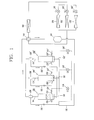
FIG. 1 is a schematic diagram of an air conditioner having a plurality of compressors according to an embodiment; -
FIG. 2 is a cross-sectional view of internal structure of a compressor and an oil separator ofFIG.1 ; -
FIG. 3 is a flow chart of a method of operating the air conditioner ofFIG. 1 ; -
FIG. 4 is a schematic diagram of an air conditioner having a plurality of compressors according to another embodiment; -
FIG. 5 is a flow chart of a method of operating the air conditioner ofFIG. 4 ; -
FIG. 6 is a schematic diagram of an air conditioner having a plurality of compressors according to another embodiment; and -
FIG. 7 is a flow chart of a method of operating the air conditioner ofFIG. 6 . - Hereinafter, embodiments for an operating method for an air conditioner with multiple compressors according to the present invention will be described in detail with reference to the accompanying drawings.
-
FIG. 1 is a schematic diagram of an air conditioner having a plurality of compressors according to an embodiment. Referring toFIG. 1 , the air conditioner may include a plurality ofcompressors first suction pipe 110, through which refrigerant may flow, and asecond suction pipe first suction pipe 110 to eachrespective compressor compressor respective discharge pipes - Oil may be stored inside the compressor, which may serve to lower friction within the compressor during operation. Further, an oil
level detecting sensor oil return pipe respective compressor first suction pipe 110 to redistribute the oil received from the firstoil return pipe oil return pipes oil return pipes solenoid valves oil return pipes - The
discharge pipes oil separators oil separators second oil separators first suction pipe 110. The separated refrigerant, and any remaining oil, may be discharged from theoil separators way valve 140. Thus, the discharged oil may be separated from the refrigerant by theoil separators compressors first suction pipe 110 and thesecond suction pipes - The 4-
way valve 140 may include, for example, three discharge ports, which may be connected to anaccumulator 180, an outdoor-side heat exchanger 150, and one or more indoor-side heat exchanger(s) 170, 170', 170", respectively. The air conditioner may provide either cooling or heating based on a switching state of the 4-way valve 140. Simply for ease of explanation, the 4-way valve as shown inFIG. 1 is configured to provide cooling to the indoor-side. - In the embodiment of
Fig. 1 , the refrigerant discharged from the 4-way valve 140 may be passed through the outdoor-side heat exchanger 150 andexpansion apparatuses side heat exchangers way valve 140 into theaccumulator 180. Once refrigerant remaining in a liquid state is separated from refrigerant in a gaseous state, theaccumulator 180 may pass the gaseous refrigerant to thefirst suction pipe 110. -
FIG. 2 is a cross-sectional view of internal structure of a compressor and an oil separator ofFig. 1 .Compressors 100', 100" andoil separators 130', 130" ofFig. 1 may have the same structure ascompressor 100 andoil separator 130 ofFig. 1 . Therefore, repetitive description of thecompressors 100', 100" andoil separators 130',130" has been omitted hereinafter. - Simply for ease of explanation, embodiments are described herein in the form of a scroll compressor. However, embodiments are not limited thereto and may be applied to or employ any type of compressor in which oil is stored inside of the compressor. Referring to
FIG. 2 , amain frame 20 and asub frame 30 may be provided inside a container orcase 10, and a drive motor 40, which is a driving device, may be provided between themain frame 20 andsub frame 30. A compression device that compresses refrigerant may be combined with the drive motor 40. The compression device may include a fixedscroll 50 and anorbiting scroll 60, which may be provided at an upper side of themain frame 20. Further, a suction port SP may be formed on thecontainer 10 and may be connected to thesecond suction pipe 112. The compressed refrigerant may be supplied from thecompressor 100 to theoil separator 130 via thedischarge pipe 114. - The
oil separator 130 may include adischarge pipe 131 at an upper side thereof and dischargeport 133 at a lower side thereof. Thedischarge port 133 may be connected to the secondoil return pipe 132. Thedischarge pipe 131 may extend to a middle portion of theoil separator 130, and thus, may lengthen a flow path of the compressed refrigerant in theoil separator 130. Accordingly, as compressed refrigerant is discharged from thedischarge pipe 131 to the 4-way valve 140, any oil that remains in the compressed refrigerant may be separated therefrom and collected in a lower portion of theoil separator 130. The separated oil, once collected, may be discharged from theoil separator 130 via thedischarge port 133 to the secondoil return pipe 132. - The drive motor 40 may include a
stator 41, which may be wound with a coil, a rotor 42 rotatably inserted in thestator 41, and arotating shaft 43 attached to a center of the rotor 42 that transfers rotary force to a compression mechanism. A drivingpin portion 44 may be formed to protrude at an upper end of therotating shaft 43. The drivingpin portion 44 may be formed adjacent to a rotational axis of therotating shaft 43. That is, the drivingpin portion 44 may be positioned away from a rotational center of therotating shaft 43. - The
compressor 100 may further include the fixedscroll 50, which may be fixed to an upper surface of themain frame 20, the orbitingscroll 60, which may be placed on an upper surface of themain frame 20 and engaged with the fixedscroll 50, and anOldham ring 70 disposed between the orbitingscroll 60 and themain frame 20 to prevent the rotation of the orbitingscroll 60. A fixedwrap 51 may be spirally wound and formed on the fixedscroll 50. Further, an orbitingwrap 61 may be spirally wound and formed on theorbiting scroll 60. The fixedwrap 51 together with the orbitingwrap 61 may form a compression chamber (P). Aboss portion 62 may protrude at a bottom surface of the orbitingscroll 60, for example, a lateral surface opposite the orbitingwrap 61. Theboss portion 62 may engage therotating shaft 43 to receive a rotary force therefrom. - A sliding
bush 63 may be combined with the drivingpin portion 44 of therotating shaft 43 to slide in a radial direction. The slidingbush 63 may then be combined with the boss portion 162 of the orbitingscroll 60 to slide in a rotating direction. An external diameter of the slidingbush 63 may be formed to be the same as an internal diameter of theboss portion 62 of the orbitingscroll 60, to thereby reduce friction between therotating shaft 43 and the orbitingscroll 60. Further, amain frame bush 22 may be provided on an inside surface of themain frame 120 to reduce friction between therotating shaft 43 andmain frame 20. Oil may be supplied by anoil feeder 180 provided at a lower end portion of therotating shaft 43 to lubricate each of thebushes - The oil may be stored in an oil storage space formed by an inner surface of a
base 12 of thecontainer 10. The oil may be pumped from the oil storage space and supplied to the compression device through anoil flow path 43a formed inside the rotatingshaft 43. Theoil feeder 80, which may be provided at a lower end portion of theoil flow path 43a, may rotate with the rotatingshaft 43 to pump the oil from the oil storage space into theoil flow path 43a. The pumped oil may then be supplied to the compression device positioned at an upper portion of theoil flow path 43a. - In order for the oil to be supplied by the
oil feeder 80, the oil should be maintained at appropriate levels inside thecontainer 10. However, the level of oil may vary during operation of thecompressor 100. The variation of oil level may be an absolute variation due to, for example, loss or leakage of oil, or a temporary variation in which the oil level may temporarily increase or decrease during operation based on changes in an operational speed of thecompressor 100. In either case, the oil level should be maintained in an appropriate condition, for example, within an acceptable range, during the operation of the compressor to ensure normal operation. Accordingly, an oillevel detecting sensor 102 may be provided to detect the oil level inside thecontainer 10 in real time. - The oil
level detecting sensor 102 may include a pair ofelectrodes 102a, which may protrude inside thecontainer 10. A supportingplate 102b may be provided to support the pair ofelectrodes 102a and allow them to pass through thecontainer 10 into thecompressor 100. The supportingplate 102b may be attached to a side wall of thecontainer 10 by, for example, welding or another appropriate method of attaching. Further, the supportingplate 102b may be attached to thecontainer 10 so as to be flush with an outer surface of thecontainer 10. Aflange 102c may be formed that protrudes from an outer circumference of the supportingplate 102b. Aflange anchoring portion 16, which may have a diameter greater than a diameter of the mountinghole 14, may be formed at an outer circumference of the mountinghole 14. When the supportingplate 102b is inserted into the mountinghole 14, theflange 102c may be seated on theflange anchoring portion 16 and may be attached to thecontainer 10. Accordingly, the supportingplate 102b may be mounted to thecontainer 10 at a desired position. -
FIG. 3 is a flow chart of a method of operating the air conditioner ofFIG. 1 . Referring toFIG. 3 , once operation of the plurality of compressors is initiated, the oil level H of each compressor may first be detected, in step S01. Based on the detection result, it may then be determined whether the oil level H of each compressor is over a preset level for the respective compressor, in step S02. If the oil level H of all of the compressors is over the respective preset level, normal operation of the plurality of compressors may be initiated, in step S07. If the oil level H of some or all of the plurality of compressors is not over the preset level, then a number of compressors may be determined in which the oil level H is less than or equal to the respective preset level, in step S03. If the number of compressors having a relatively low oil level H is greater than a predetermined number of compressors, for example, the number of compressors is greater than one, then an oil collection operation may be initiated, in step S08. When the number of compressors requiring additional oil is two or more, it may be difficult to adjust the oil level in each compressor to be over the preset levels without an oil collection operation. Further, when the number of compressors is two or more, a large amount of time may be required to transfer oil between the plurality of compressors. In this case, the oil collection operation may be required. The predetermined number of compressors may be set to any number according to the number of compressors included in the air conditioner. - The oil collecting operation may transfer oil remaining inside the air conditioner, for example, in the foregoing indoor/outdoor-side heat exchanger or pipes, to the compressor(s) having a low oil level, During the oil collecting operation, the
expansion apparatus - If the number of compressors in which the oil level H is less than or equal to the respective preset level is determined to be less than or equal to the predetermined number in step S03, for example, the number of compressors is equal to one, the process may move to step S04. In step S04, the oil levels H in the compressors may be adjusted without performing an oil collecting operation. For example, a solenoid valve of the compressor in which the oil level H is greater than the preset level may be opened, and a solenoid valve of the compressor in which the oil level H is less than the preset level may be closed, in step S04. For example, referring to
FIG. 1 , if thecompressor 100 has a sufficient oil level and thecompressor 100" has a relatively low oil level, thesolenoid valve 126 may be opened and thesolenoid valve 126" may be closed. - With the solenoid valves configured as above, a normal operation of the compressors may be carried out for a predetermined period of time, for example, approximately five minutes, in step S05. During the normal operation of the compressors, oil may be collected from the
compressor 100 having a sufficient oil level, which may then be uniformly distributed and supplied to each compressor through the first and the second suction pipes. However, as thesolenoid valve 112" of thecompressor 100" having a relatively low oil level is closed, oil is not collected fromcompressor 100". The oil level in thecompressor 100" may therefore gradually increase above the preset level. Accordingly, an oil level of a compressor having insufficient oil may be increased above the preset level when a total amount of oil stored in the air conditioner is sufficient. - However, it may be difficult to adjust the oil level of each compressor over a desired level in spite of the foregoing process when a total amount of oil remaining inside all of the compressors, for example, a total amount of oil in the air conditioning system, is insufficient to be redistributed. Thus, as previously described, the normal operation may be carried out for the predetermined period of time, for example, approximately 5 minutes, in step S05. Thereafter, the oil levels H of the compressors may be checked again, and if the oil level H of all of the compressors is over each respective preset level, in step S06 the compressors may return to normal operation, in step S06. Otherwise, if the oil level H of all of the compressors is not above the respective preset levels, the oil collecting operation may be performed, in step S08.
-
FIG. 4 is a schematic diagram of an air conditioner according to another embodiment. Referring toFIG. 4 , the air conditioner may temporarily store oil collected from eachcompressor oil reservoir 128 through a firstoil return pipe oil reservoir 128 may include an oillevel detecting sensor 128a that detects an oil level inside theoil reservoir 128 and avalve 128b that controls a flow of oil discharged from theoil reservoir 128. Theoil reservoir 128 may store oil exceeding a preset level received from each of thecompressors first suction pipe 110 and thesecond suction pipes -
FIG. 5 is a flow chart of a method of operating the air conditioner ofFIG. 4 . After detecting an oil level H of each compressor, in step S10, a number of compressors in which the oil level H is lower than or equal to a respective preset level is determined. If the number of compressors is less than or equal to a predetermined number, for example, the predetermined number is one, in step S11, then it may be determined whether all of the compressors have sufficient amounts of oil, in step S12. If the oil level H of all of the compressors is above the respective preset level, then the compressors are operated in normal operation, in step S16. If it is determined in step S12 that the oil level H of all of the compressors is not over the respective preset level, then asolenoid valve 126 of each compressor in which the oil level H is greater than a respective preset level may be opened, and avalve 126" of the compressor in which H is less than or equal to the desired level may be closed, in step S13. - A normal operation of the compressors may be carried out in this state for a predetermined amount of time, for example, about five minutes, in step S14. Then, oil collected from each of the compressors having a sufficient amount of oil may be uniformly distributed and supplied to all compressors through the first and the second suction pipes. However, oil is not collected from a compressor for which the solenoid valve is closed. Further, oil may be collected again even if it is supplied to a compressor for which the solenoid valve is open, thereby maintaining the oil level over a preset level. Accordingly, the oil levels in each of the compressors may be maintained over a preset level when the total amount oil stored by the compressors is sufficient.
- However, it may be difficult to adjust the oil level of a compressor to be over a preset level in spite of this process when the total amount of oil remaining inside the compressors is insufficient. Thus, as previously described, a normal operation of the compressors may be carried out for the predetermined period of time, for example, approximately 5 minutes, in step S14. Then, the oil level of each of the compressors may be checked again, and in step S16, if the oil level H of all compressors is over each respective preset level, in step S15, a normal operation may be carried out. Otherwise, an oil collecting operation may be performed, in step S20.
- In step S11, if the number of the compressors having a relatively low oil level (H is below respective preset level) is greater than the predetermined number, for example, the predetermined number is one then an oil level of the oil reservoir (HR) may be detected, in step S17. After detecting the oil level HR of the oil reservoir, the oil collecting operation may be performed, in step S20, if the oil level HR of the oil reservoir is lower than or equal to a preset level of the reservoir, in step S18. Otherwise, if HR is greater than the preset level, the
reservoir valve 128b may opened, in step S19, and thesolenoid valves -
FIG. 6 is a schematic diagram of an air conditioner according to another embodiment. Referring toFIG. 6 , a plurality ofcompressors oil separator 230. An oillevel detecting sensor 231 that detects an oil level Hs inside theoil separator 230 may be provided in theoil separator 230. Further, a secondoil return pipe 232 that supplies the oil stored in theoil separator 230 to thecompressors oil return pipe 232 may be connected tooil replenishing pipes second suction pipes oil replenishing pipes valves respective compressor - The
valves level detecting sensors compressors 200, 200' because the respective oil levels are greater than a respective preset level,corresponding valves 236, 236' may be closed. However, if additional oil is required incompressor 200" because a corresponding oil level is less than a preset level,valve 236" may be opened to supply oil stored in theoil separator 230 tocompressor 200". -
FIG. 7 is a flow chart of a method of operating the air conditioner ofFIG. 6 . After detecting an oil level H of each compressor, in step S21, a number of compressors in which the oil level H is lower than or equal to a respective preset level is determined, in step S22. If the number of compressors is less than or equal to a predetermined number, for example, the predetermined number is one, then it is determined whether all of the compressors have a sufficient amount of oil, in step S23. If the oil level H of all of the compressors is above the respective preset levels, then the compressors are operated in normal operation, in step S27. If the oil level H of all of the compressors are not above the preset levels, then thesolenoid valve 236" of the compressor in which H is less than or equal to the preset level may be opened, and thesolenoid valve 236, 236' of each of the compressors in which H is greater than the respective preset level may be closed, in step S24. - Thereafter, normal operation may be carried out in this state for a predetermined amount of time, for example, about five minutes, in step S25. The oil stored in the
oil separator 230 may then be provided to thecompressor 200" having the insufficient oil level during the predetermined amount of time. Then, the oil level of all of the compressors may be checked again, and if the oil level H of the all compressors is over each respective preset level, in step S26, the compressors may return to normal operation, in step S27. Otherwise, an oil collecting operation may be performed, in step S30. - Returning to step S22, if the number of the compressors in which the oil level H is less than or equal to the respective preset level is greater than the predetermined number, for example, the number of compressors is 2 or 3, then the oil level Hs of the
oil separator 230 may be detected, in step S28. After detecting the oil level Hs, the oil collecting operation may be performed, in step S30, if the oil level Hs is lower than or equal to a preset level for theoil separator 230, in step S29. Otherwise, if the oil level Hs is over the preset level, the valves of each compressor may be configured to add oil to compressors having an oil level H less than or equal to the respective preset level, in step S24.
Claims (15)
- An operating method for an air conditioner, the air conditioner comprising a plurality of compressors, each of which includes a casing that stores oil in an inner lower portion thereof and an oil level detecting device that detects an oil level in the casing; at least one first heat exchanger that intakes a working fluid from the plurality of compressors; at least one expansion device; at least one second heat exchanger, through which the working fluid passes after passing through the at least one first heat exchanger; a first suction pipe, through which the working fluid flows from the at least one first heat exchanger or the at least one second heat exchanger; and a plurality of second suction pipes branched from the first suction pipe and then connected to each of the compressors, the method comprising:detecting an oil level of each of the plurality of compressors;distributing oil in a first compressor of the plurality of compressors containing oil over a first preset level for the first compressor toward a second compressor of the plurality of compressors containing oil lower than a second preset level for the second compressor via the first and the second suction pipes without passing through the at least one first exchanger and the at least one second heat exchanger when a number of the plurality of compressors containing oil lower than the preset level for the respective compressor is less than or equal to a predetermined number; andperforming an oil collecting operation if there exists a compressor containing oil lower than a preset level for that compressor after performing the distributing or if the number of the plurality of compressors containing oil lower than the preset level for the respective compressor is greater than the predetermined number.
- The method of claim 1, wherein the distributing is performed for a predetermined period of time, at predetermined time intervals, or until all of the plurality of compressors have at least the preset level for the respective compressor.
- The method of claim 1, wherein each of the plurality of compressors includes a first oil return pipe that connects the casing of the respective compressor to the first suction pipe, and wherein oil in the respective compressor containing oil over the preset level for the respective compressor is supplied to the first suction pipe via the first oil return pipe during the distributing.
- The method of claim 3, wherein the first oil return pipe connected to a compressor containing oil lower than a preset level for each compressor remains closed during the distributing.
- The method of claim 1, wherein the air conditioner further comprises at least one oil separator having a second oil return pipe that connects the oil separator and the first suction pipe, and wherein oil collected in the oil separator is supplied to the first suction pipe via the second oil return pipe during the distributing.
- The method of claim 5, wherein the at least one oil separator receives a mixture of oil and working fluid from at least one of the plurality of compressors through an oil discharge pipe.
- The method of claim 6, wherein the at least one oil separator stores the oil from the plurality of compressors and if the number of the plurality of compressors containing oil lower than the preset level for the respective compressor is greater than the predetermined number, the method further comprises:detecting an oil level of the at least one oil separator;if the oil level of the at least one oil separator is less than a preset level for the at least one oil separator, performing the oil collecting operation; andif the oil level of the at least one oil separator is greater than or equal to the preset level, opening a valve that allows the stored oil to flow into the compressor containing oil lower than the preset level for the respective compressor.
- The method of claim 1, wherein the air conditioner further comprises a plurality of oil separators, and wherein each of the plurality of compressors discharges a mixture of oil and working fluid to a respective one of the plurality of oil separators.
- The method of claim 8, wherein the distributing includes distributing the oil stored in the at least one oil separator toward the second compressor of the plurality of compressors containing oil lower than the second preset level for the second compressor.
- The method of claim 1, wherein the air conditioner further comprises a first oil return pipe that connects the casing of each compressor to the first suction pipe, and wherein oil in the respective compressor containing oil over a preset level for each compressor and the oil in the oil separator are supplied to the first suction pipe via the first and second oil return pipes during the distributing.
- The method of claim 1, wherein the air conditioner further comprises at least one oil reservoir that stores the oil from the plurality of compressors and if the number of the plurality of compressors containing oil lower than the preset level for the respective compressor is greater than the predetermined number, the method further comprises:detecting an oil level of the at least one oil reservoir;if the oil level of the at least one reservoir is less than a preset level for the at least one oil reservoir, performing the oil collecting operation; andif the oil level of the at least one reservoir is greater than or equal to the preset level of the at least one oil reservoir, opening a reservoir valve of the at least one reservoir as part of the distributing.
- The method of claim 11, wherein each of the plurality of compressors includes a first oil return pipe that connects the casing of the respective compressor to the at least one oil reservoir, and wherein oil in the respective compressor containing oil over the preset level for the respective compressor is supplied to the at least one oil reservoir via the first oil return pipe.
- The method of claim 12, wherein the first oil return pipe connected to the compressor containing oil lower than a preset level for each compressor remains closed during the distributing.
- The method of claim 11, wherein the at least one oil reservoir functions as an oil separator.
- The method of claim 14, wherein the oil separator receives a mixture of oil and working fluid from at least one of the plurality of compressors through an oil discharge pipe.
Applications Claiming Priority (1)
| Application Number | Priority Date | Filing Date | Title |
|---|---|---|---|
| KR20100030120A KR101495186B1 (en) | 2010-04-01 | 2010-04-01 | Air conditioner with multiple compressors and an operation method thereof |
Publications (3)
| Publication Number | Publication Date |
|---|---|
| EP2375193A2 true EP2375193A2 (en) | 2011-10-12 |
| EP2375193A3 EP2375193A3 (en) | 2011-11-30 |
| EP2375193B1 EP2375193B1 (en) | 2013-03-06 |
Family
ID=44310311
Family Applications (1)
| Application Number | Title | Priority Date | Filing Date |
|---|---|---|---|
| EP10188151A Active EP2375193B1 (en) | 2010-04-01 | 2010-10-20 | Operating method for air conditioner with multiple compressors |
Country Status (4)
| Country | Link |
|---|---|
| US (1) | US20110239667A1 (en) |
| EP (1) | EP2375193B1 (en) |
| KR (1) | KR101495186B1 (en) |
| CN (1) | CN102213474B (en) |
Cited By (1)
| Publication number | Priority date | Publication date | Assignee | Title |
|---|---|---|---|---|
| CN107923403A (en) * | 2015-08-11 | 2018-04-17 | 艾默生环境优化技术有限公司 | Multi-compressor configuration with oil balancing system |
Families Citing this family (22)
| Publication number | Priority date | Publication date | Assignee | Title |
|---|---|---|---|---|
| KR101977984B1 (en) * | 2012-07-11 | 2019-05-14 | 엘지전자 주식회사 | Air conditioner and method for controlling the same |
| KR101356312B1 (en) * | 2012-08-01 | 2014-01-29 | 엘지전자 주식회사 | Air conditioner and method for controlling the same |
| CN103671119A (en) * | 2012-09-24 | 2014-03-26 | 珠海格力电器股份有限公司 | Oil level control system and method and screw compressor set |
| CN103062872B (en) * | 2013-01-11 | 2015-06-17 | 四川长虹电器股份有限公司 | Household air conditioner integrated control system and starting method thereof |
| CN103062841B (en) * | 2013-01-18 | 2015-08-19 | 四川长虹电器股份有限公司 | A kind of air-conditioning system, control system and air conditioning control method |
| JP5940489B2 (en) * | 2013-05-21 | 2016-06-29 | ジョンソンコントロールズ ヒタチ エア コンディショニング テクノロジー(ホンコン)リミテッド | Air conditioner |
| JP6143633B2 (en) | 2013-10-15 | 2017-06-07 | 住友重機械工業株式会社 | Compressor and compressor oil quantity management system |
| KR102073011B1 (en) | 2013-12-18 | 2020-03-02 | 삼성전자주식회사 | Oil detecting apparatus, compressor having the same and method for controlling compressor |
| KR102198326B1 (en) * | 2013-12-26 | 2021-01-05 | 엘지전자 주식회사 | Air conditioner |
| EP3023713A1 (en) * | 2014-11-19 | 2016-05-25 | Danfoss A/S | A method for controlling a vapour compression system with an ejector |
| JP6476810B2 (en) * | 2014-12-10 | 2019-03-06 | ダイキン工業株式会社 | Compressor preheating device |
| KR101639513B1 (en) * | 2015-01-12 | 2016-07-13 | 엘지전자 주식회사 | Air conditioner and method for controlling the same |
| EP3334985B1 (en) | 2015-08-14 | 2019-05-01 | Danfoss A/S | A vapour compression system with at least two evaporator groups |
| CN105091441B (en) * | 2015-08-25 | 2017-12-26 | 珠海格力电器股份有限公司 | Air-conditioning system and its oil circulation amount regulating system and method |
| CN105180533B (en) * | 2015-09-11 | 2018-02-16 | 珠海格力电器股份有限公司 | Screw chiller method for controlling oil return, system and Screw chiller |
| CA2997658A1 (en) | 2015-10-20 | 2017-04-27 | Danfoss A/S | A method for controlling a vapour compression system with a variable receiver pressure setpoint |
| BR112018007270A2 (en) | 2015-10-20 | 2018-10-30 | Danfoss As | method for controlling an ejector mode steam compression system for an extended time |
| US20180195794A1 (en) * | 2017-01-12 | 2018-07-12 | Emerson Climate Technologies, Inc. | Diagnostics And Control For Micro Booster Supermarket Refrigeration System |
| GB2566538A (en) * | 2017-09-18 | 2019-03-20 | J & E Hall Ltd | Oil separator |
| US11713760B2 (en) * | 2017-12-28 | 2023-08-01 | Emerson Climate Technologies (Suzhou) Co., Ltd. | Intake pipe used for compressor system and compressor system |
| DK180146B1 (en) | 2018-10-15 | 2020-06-25 | Danfoss As Intellectual Property | Heat exchanger plate with strenghened diagonal area |
| US11460224B2 (en) * | 2018-10-31 | 2022-10-04 | Emerson Climate Technologies, Inc. | Oil control for climate-control system |
Family Cites Families (23)
| Publication number | Priority date | Publication date | Assignee | Title |
|---|---|---|---|---|
| US4478050A (en) * | 1982-11-19 | 1984-10-23 | Hussmann Corporation | Oil separation for refrigeration system |
| US4589263A (en) * | 1984-04-12 | 1986-05-20 | Hussmann Corporation | Multiple compressor oil system |
| GB2215866B (en) * | 1988-02-09 | 1992-06-24 | Toshiba Kk | Multi-type air conditioner system with oil level control for parallel operated compressor therein |
| JP2865707B2 (en) * | 1989-06-14 | 1999-03-08 | 株式会社日立製作所 | Refrigeration equipment |
| JP3163121B2 (en) * | 1991-06-28 | 2001-05-08 | 東芝キヤリア株式会社 | Air conditioner |
| US5327997A (en) * | 1993-01-22 | 1994-07-12 | Temprite, Inc. | Lubrication management system |
| US5321956A (en) * | 1993-05-26 | 1994-06-21 | Kemp Industrial Refrigeration, Inc. | Oil management and removal system for a refrigeration installation |
| AUPM630094A0 (en) * | 1994-06-17 | 1994-07-14 | Refrigerant Monitoring Systems Pty Ltd | Oil level control device |
| EP0838640A3 (en) * | 1996-10-28 | 1998-06-17 | Matsushita Refrigeration Company | Oil level equalizing system for plural compressors |
| KR20040010740A (en) * | 2002-04-08 | 2004-01-31 | 다이킨 고교 가부시키가이샤 | Refrigeration apparatus |
| JP3478292B2 (en) * | 2002-05-28 | 2003-12-15 | ダイキン工業株式会社 | Compression mechanism of refrigeration system |
| JP4300804B2 (en) * | 2002-06-11 | 2009-07-22 | ダイキン工業株式会社 | Oil leveling circuit of compression mechanism, heat source unit of refrigeration apparatus, and refrigeration apparatus including the same |
| JP4173784B2 (en) * | 2003-08-29 | 2008-10-29 | 三星電子株式会社 | Multi-compressor oil leveling system |
| CN1690603A (en) * | 2004-04-30 | 2005-11-02 | 乐金电子(天津)电器有限公司 | Air-liquid separator for air conditioners |
| JP3939314B2 (en) * | 2004-06-10 | 2007-07-04 | 三星電子株式会社 | Air conditioner and oil equalizing operation method thereof |
| EP1780416A4 (en) * | 2004-08-03 | 2011-03-09 | Maekawa Seisakusho Kk | Lubricant supply system and operating method of multisystem lubrication screw compressor |
| US7231783B2 (en) * | 2004-08-27 | 2007-06-19 | Zero Zone, Inc. | Oil control system for a refrigeration system |
| KR100758901B1 (en) * | 2004-11-17 | 2007-09-14 | 엘지전자 주식회사 | Multi-type air conditioner |
| KR20080032870A (en) * | 2006-10-11 | 2008-04-16 | 엘지전자 주식회사 | A compressor oil retrieving apparatus of multi-type air conditioner and oil return method thereof |
| KR101266657B1 (en) * | 2006-10-17 | 2013-05-28 | 엘지전자 주식회사 | air conditioner |
| KR100878819B1 (en) * | 2007-03-02 | 2009-01-14 | 엘지전자 주식회사 | Air conditioner and control method for the same |
| KR101480546B1 (en) * | 2007-10-25 | 2015-01-08 | 엘지전자 주식회사 | Air conditioner |
| KR20090041846A (en) * | 2007-10-25 | 2009-04-29 | 엘지전자 주식회사 | Air conditioner |
-
2010
- 2010-04-01 KR KR20100030120A patent/KR101495186B1/en active IP Right Grant
- 2010-10-20 EP EP10188151A patent/EP2375193B1/en active Active
- 2010-11-12 CN CN201010547580.8A patent/CN102213474B/en not_active Expired - Fee Related
- 2010-12-02 US US12/958,915 patent/US20110239667A1/en not_active Abandoned
Non-Patent Citations (1)
| Title |
|---|
| None |
Cited By (4)
| Publication number | Priority date | Publication date | Assignee | Title |
|---|---|---|---|---|
| CN107923403A (en) * | 2015-08-11 | 2018-04-17 | 艾默生环境优化技术有限公司 | Multi-compressor configuration with oil balancing system |
| EP3334940A4 (en) * | 2015-08-11 | 2019-04-03 | Emerson Climate Technologies, Inc. | Multiple compressor configuration with oil-balancing system |
| CN107923403B (en) * | 2015-08-11 | 2019-08-13 | 艾默生环境优化技术有限公司 | Multi-compressor configuration with oil balancing system |
| US10641268B2 (en) | 2015-08-11 | 2020-05-05 | Emerson Climate Technologies, Inc. | Multiple compressor configuration with oil-balancing system |
Also Published As
| Publication number | Publication date |
|---|---|
| EP2375193B1 (en) | 2013-03-06 |
| KR20110110662A (en) | 2011-10-07 |
| KR101495186B1 (en) | 2015-02-24 |
| CN102213474A (en) | 2011-10-12 |
| EP2375193A3 (en) | 2011-11-30 |
| CN102213474B (en) | 2014-03-12 |
| US20110239667A1 (en) | 2011-10-06 |
Similar Documents
| Publication | Publication Date | Title |
|---|---|---|
| EP2375193B1 (en) | Operating method for air conditioner with multiple compressors | |
| US7931453B2 (en) | Capacity variable device for rotary compressor and driving method of air conditioner having the same | |
| AU2007241898B2 (en) | Refrigeration system | |
| US20160186754A1 (en) | Scroll compressor and air conditioner having the same | |
| EP1703231A1 (en) | Apparatus and method for equalizing oil for multiple compressors | |
| JP2000179481A (en) | Scroll type compressor | |
| KR20080035982A (en) | Scroll compressor and freezing cycle using the same | |
| WO2007123087A1 (en) | Refrigerating apparatus | |
| EP1526340B1 (en) | Method and apparatus for preventing the accumulation of liquid refrigerant in an air conditioner | |
| JP2005201145A (en) | Scroll type compressor | |
| WO2017221398A1 (en) | Rotary compressor and refrigeration cycle device | |
| CN111365874A (en) | Refrigerant circulating system | |
| CN203362462U (en) | Compressor system | |
| WO2010122812A1 (en) | Refrigeration cycle device | |
| DE112018002522B4 (en) | screw compactor | |
| JP3361000B2 (en) | Refrigeration cycle device | |
| JPH0559278B2 (en) | ||
| JP3114418B2 (en) | Compressor and refrigeration apparatus provided with the compressor | |
| JP4720594B2 (en) | Refrigeration equipment | |
| KR20070066294A (en) | Refrigeration system | |
| JP3229125B2 (en) | Refrigeration air conditioner | |
| JPH01195982A (en) | Control of compressor | |
| JPH08144953A (en) | Oil feeder for compressor | |
| JP4816316B2 (en) | Compression device | |
| JPS6245110Y2 (en) |
Legal Events
| Date | Code | Title | Description |
|---|---|---|---|
| PUAI | Public reference made under article 153(3) epc to a published international application that has entered the european phase |
Free format text: ORIGINAL CODE: 0009012 |
|
| 17P | Request for examination filed |
Effective date: 20101020 |
|
| AK | Designated contracting states |
Kind code of ref document: A2 Designated state(s): AL AT BE BG CH CY CZ DE DK EE ES FI FR GB GR HR HU IE IS IT LI LT LU LV MC MK MT NL NO PL PT RO RS SE SI SK SM TR |
|
| AX | Request for extension of the european patent |
Extension state: BA ME |
|
| PUAL | Search report despatched |
Free format text: ORIGINAL CODE: 0009013 |
|
| AK | Designated contracting states |
Kind code of ref document: A3 Designated state(s): AL AT BE BG CH CY CZ DE DK EE ES FI FR GB GR HR HU IE IS IT LI LT LU LV MC MK MT NL NO PL PT RO RS SE SI SK SM TR |
|
| AX | Request for extension of the european patent |
Extension state: BA ME |
|
| RIC1 | Information provided on ipc code assigned before grant |
Ipc: F25B 31/00 20060101AFI20111024BHEP |
|
| RAP1 | Party data changed (applicant data changed or rights of an application transferred) |
Owner name: LG ELECTRONICS INC. |
|
| GRAP | Despatch of communication of intention to grant a patent |
Free format text: ORIGINAL CODE: EPIDOSNIGR1 |
|
| GRAS | Grant fee paid |
Free format text: ORIGINAL CODE: EPIDOSNIGR3 |
|
| GRAP | Despatch of communication of intention to grant a patent |
Free format text: ORIGINAL CODE: EPIDOSNIGR1 |
|
| GRAA | (expected) grant |
Free format text: ORIGINAL CODE: 0009210 |
|
| AK | Designated contracting states |
Kind code of ref document: B1 Designated state(s): AL AT BE BG CH CY CZ DE DK EE ES FI FR GB GR HR HU IE IS IT LI LT LU LV MC MK MT NL NO PL PT RO RS SE SI SK SM TR |
|
| REG | Reference to a national code |
Ref country code: GB Ref legal event code: FG4D |
|
| REG | Reference to a national code |
Ref country code: CH Ref legal event code: EP Ref country code: AT Ref legal event code: REF Ref document number: 599863 Country of ref document: AT Kind code of ref document: T Effective date: 20130315 |
|
| REG | Reference to a national code |
Ref country code: IE Ref legal event code: FG4D |
|
| REG | Reference to a national code |
Ref country code: DE Ref legal event code: R096 Ref document number: 602010005225 Country of ref document: DE Effective date: 20130502 |
|
| REG | Reference to a national code |
Ref country code: AT Ref legal event code: MK05 Ref document number: 599863 Country of ref document: AT Kind code of ref document: T Effective date: 20130306 |
|
| PG25 | Lapsed in a contracting state [announced via postgrant information from national office to epo] |
Ref country code: BG Free format text: LAPSE BECAUSE OF FAILURE TO SUBMIT A TRANSLATION OF THE DESCRIPTION OR TO PAY THE FEE WITHIN THE PRESCRIBED TIME-LIMIT Effective date: 20130606 Ref country code: SE Free format text: LAPSE BECAUSE OF FAILURE TO SUBMIT A TRANSLATION OF THE DESCRIPTION OR TO PAY THE FEE WITHIN THE PRESCRIBED TIME-LIMIT Effective date: 20130306 Ref country code: ES Free format text: LAPSE BECAUSE OF FAILURE TO SUBMIT A TRANSLATION OF THE DESCRIPTION OR TO PAY THE FEE WITHIN THE PRESCRIBED TIME-LIMIT Effective date: 20130617 Ref country code: LT Free format text: LAPSE BECAUSE OF FAILURE TO SUBMIT A TRANSLATION OF THE DESCRIPTION OR TO PAY THE FEE WITHIN THE PRESCRIBED TIME-LIMIT Effective date: 20130306 Ref country code: NO Free format text: LAPSE BECAUSE OF FAILURE TO SUBMIT A TRANSLATION OF THE DESCRIPTION OR TO PAY THE FEE WITHIN THE PRESCRIBED TIME-LIMIT Effective date: 20130606 Ref country code: AT Free format text: LAPSE BECAUSE OF FAILURE TO SUBMIT A TRANSLATION OF THE DESCRIPTION OR TO PAY THE FEE WITHIN THE PRESCRIBED TIME-LIMIT Effective date: 20130306 |
|
| REG | Reference to a national code |
Ref country code: NL Ref legal event code: VDEP Effective date: 20130306 |
|
| REG | Reference to a national code |
Ref country code: LT Ref legal event code: MG4D |
|
| PG25 | Lapsed in a contracting state [announced via postgrant information from national office to epo] |
Ref country code: GR Free format text: LAPSE BECAUSE OF FAILURE TO SUBMIT A TRANSLATION OF THE DESCRIPTION OR TO PAY THE FEE WITHIN THE PRESCRIBED TIME-LIMIT Effective date: 20130607 Ref country code: LV Free format text: LAPSE BECAUSE OF FAILURE TO SUBMIT A TRANSLATION OF THE DESCRIPTION OR TO PAY THE FEE WITHIN THE PRESCRIBED TIME-LIMIT Effective date: 20130306 Ref country code: SI Free format text: LAPSE BECAUSE OF FAILURE TO SUBMIT A TRANSLATION OF THE DESCRIPTION OR TO PAY THE FEE WITHIN THE PRESCRIBED TIME-LIMIT Effective date: 20130306 Ref country code: FI Free format text: LAPSE BECAUSE OF FAILURE TO SUBMIT A TRANSLATION OF THE DESCRIPTION OR TO PAY THE FEE WITHIN THE PRESCRIBED TIME-LIMIT Effective date: 20130306 |
|
| PG25 | Lapsed in a contracting state [announced via postgrant information from national office to epo] |
Ref country code: HR Free format text: LAPSE BECAUSE OF FAILURE TO SUBMIT A TRANSLATION OF THE DESCRIPTION OR TO PAY THE FEE WITHIN THE PRESCRIBED TIME-LIMIT Effective date: 20130306 Ref country code: BE Free format text: LAPSE BECAUSE OF FAILURE TO SUBMIT A TRANSLATION OF THE DESCRIPTION OR TO PAY THE FEE WITHIN THE PRESCRIBED TIME-LIMIT Effective date: 20130306 Ref country code: RS Free format text: LAPSE BECAUSE OF FAILURE TO SUBMIT A TRANSLATION OF THE DESCRIPTION OR TO PAY THE FEE WITHIN THE PRESCRIBED TIME-LIMIT Effective date: 20130306 |
|
| PG25 | Lapsed in a contracting state [announced via postgrant information from national office to epo] |
Ref country code: NL Free format text: LAPSE BECAUSE OF FAILURE TO SUBMIT A TRANSLATION OF THE DESCRIPTION OR TO PAY THE FEE WITHIN THE PRESCRIBED TIME-LIMIT Effective date: 20130306 Ref country code: SK Free format text: LAPSE BECAUSE OF FAILURE TO SUBMIT A TRANSLATION OF THE DESCRIPTION OR TO PAY THE FEE WITHIN THE PRESCRIBED TIME-LIMIT Effective date: 20130306 Ref country code: RO Free format text: LAPSE BECAUSE OF FAILURE TO SUBMIT A TRANSLATION OF THE DESCRIPTION OR TO PAY THE FEE WITHIN THE PRESCRIBED TIME-LIMIT Effective date: 20130306 Ref country code: PT Free format text: LAPSE BECAUSE OF FAILURE TO SUBMIT A TRANSLATION OF THE DESCRIPTION OR TO PAY THE FEE WITHIN THE PRESCRIBED TIME-LIMIT Effective date: 20130708 Ref country code: IS Free format text: LAPSE BECAUSE OF FAILURE TO SUBMIT A TRANSLATION OF THE DESCRIPTION OR TO PAY THE FEE WITHIN THE PRESCRIBED TIME-LIMIT Effective date: 20130706 Ref country code: CZ Free format text: LAPSE BECAUSE OF FAILURE TO SUBMIT A TRANSLATION OF THE DESCRIPTION OR TO PAY THE FEE WITHIN THE PRESCRIBED TIME-LIMIT Effective date: 20130306 Ref country code: EE Free format text: LAPSE BECAUSE OF FAILURE TO SUBMIT A TRANSLATION OF THE DESCRIPTION OR TO PAY THE FEE WITHIN THE PRESCRIBED TIME-LIMIT Effective date: 20130306 |
|
| PG25 | Lapsed in a contracting state [announced via postgrant information from national office to epo] |
Ref country code: PL Free format text: LAPSE BECAUSE OF FAILURE TO SUBMIT A TRANSLATION OF THE DESCRIPTION OR TO PAY THE FEE WITHIN THE PRESCRIBED TIME-LIMIT Effective date: 20130306 |
|
| PLBE | No opposition filed within time limit |
Free format text: ORIGINAL CODE: 0009261 |
|
| STAA | Information on the status of an ep patent application or granted ep patent |
Free format text: STATUS: NO OPPOSITION FILED WITHIN TIME LIMIT |
|
| PG25 | Lapsed in a contracting state [announced via postgrant information from national office to epo] |
Ref country code: DK Free format text: LAPSE BECAUSE OF FAILURE TO SUBMIT A TRANSLATION OF THE DESCRIPTION OR TO PAY THE FEE WITHIN THE PRESCRIBED TIME-LIMIT Effective date: 20130306 |
|
| 26N | No opposition filed |
Effective date: 20131209 |
|
| REG | Reference to a national code |
Ref country code: DE Ref legal event code: R097 Ref document number: 602010005225 Country of ref document: DE Effective date: 20131209 |
|
| PG25 | Lapsed in a contracting state [announced via postgrant information from national office to epo] |
Ref country code: MC Free format text: LAPSE BECAUSE OF FAILURE TO SUBMIT A TRANSLATION OF THE DESCRIPTION OR TO PAY THE FEE WITHIN THE PRESCRIBED TIME-LIMIT Effective date: 20130306 |
|
| REG | Reference to a national code |
Ref country code: IE Ref legal event code: MM4A |
|
| PG25 | Lapsed in a contracting state [announced via postgrant information from national office to epo] |
Ref country code: IE Free format text: LAPSE BECAUSE OF NON-PAYMENT OF DUE FEES Effective date: 20131020 |
|
| PG25 | Lapsed in a contracting state [announced via postgrant information from national office to epo] |
Ref country code: SM Free format text: LAPSE BECAUSE OF FAILURE TO SUBMIT A TRANSLATION OF THE DESCRIPTION OR TO PAY THE FEE WITHIN THE PRESCRIBED TIME-LIMIT Effective date: 20130306 |
|
| REG | Reference to a national code |
Ref country code: CH Ref legal event code: PL |
|
| GBPC | Gb: european patent ceased through non-payment of renewal fee |
Effective date: 20141020 |
|
| PG25 | Lapsed in a contracting state [announced via postgrant information from national office to epo] |
Ref country code: CY Free format text: LAPSE BECAUSE OF FAILURE TO SUBMIT A TRANSLATION OF THE DESCRIPTION OR TO PAY THE FEE WITHIN THE PRESCRIBED TIME-LIMIT Effective date: 20130306 Ref country code: TR Free format text: LAPSE BECAUSE OF FAILURE TO SUBMIT A TRANSLATION OF THE DESCRIPTION OR TO PAY THE FEE WITHIN THE PRESCRIBED TIME-LIMIT Effective date: 20130306 |
|
| PG25 | Lapsed in a contracting state [announced via postgrant information from national office to epo] |
Ref country code: GB Free format text: LAPSE BECAUSE OF NON-PAYMENT OF DUE FEES Effective date: 20141020 Ref country code: HU Free format text: LAPSE BECAUSE OF FAILURE TO SUBMIT A TRANSLATION OF THE DESCRIPTION OR TO PAY THE FEE WITHIN THE PRESCRIBED TIME-LIMIT; INVALID AB INITIO Effective date: 20101020 Ref country code: LI Free format text: LAPSE BECAUSE OF NON-PAYMENT OF DUE FEES Effective date: 20141031 Ref country code: CH Free format text: LAPSE BECAUSE OF NON-PAYMENT OF DUE FEES Effective date: 20141031 Ref country code: LU Free format text: LAPSE BECAUSE OF NON-PAYMENT OF DUE FEES Effective date: 20131020 Ref country code: MK Free format text: LAPSE BECAUSE OF FAILURE TO SUBMIT A TRANSLATION OF THE DESCRIPTION OR TO PAY THE FEE WITHIN THE PRESCRIBED TIME-LIMIT Effective date: 20130306 |
|
| PG25 | Lapsed in a contracting state [announced via postgrant information from national office to epo] |
Ref country code: MT Free format text: LAPSE BECAUSE OF FAILURE TO SUBMIT A TRANSLATION OF THE DESCRIPTION OR TO PAY THE FEE WITHIN THE PRESCRIBED TIME-LIMIT Effective date: 20130306 |
|
| REG | Reference to a national code |
Ref country code: FR Ref legal event code: PLFP Year of fee payment: 6 |
|
| REG | Reference to a national code |
Ref country code: FR Ref legal event code: PLFP Year of fee payment: 7 |
|
| REG | Reference to a national code |
Ref country code: FR Ref legal event code: PLFP Year of fee payment: 8 |
|
| REG | Reference to a national code |
Ref country code: FR Ref legal event code: PLFP Year of fee payment: 9 |
|
| PG25 | Lapsed in a contracting state [announced via postgrant information from national office to epo] |
Ref country code: AL Free format text: LAPSE BECAUSE OF FAILURE TO SUBMIT A TRANSLATION OF THE DESCRIPTION OR TO PAY THE FEE WITHIN THE PRESCRIBED TIME-LIMIT Effective date: 20130306 |
|
| PGFP | Annual fee paid to national office [announced via postgrant information from national office to epo] |
Ref country code: FR Payment date: 20190906 Year of fee payment: 10 |
|
| PGFP | Annual fee paid to national office [announced via postgrant information from national office to epo] |
Ref country code: DE Payment date: 20190905 Year of fee payment: 10 |
|
| REG | Reference to a national code |
Ref country code: DE Ref legal event code: R119 Ref document number: 602010005225 Country of ref document: DE |
|
| PG25 | Lapsed in a contracting state [announced via postgrant information from national office to epo] |
Ref country code: DE Free format text: LAPSE BECAUSE OF NON-PAYMENT OF DUE FEES Effective date: 20210501 Ref country code: FR Free format text: LAPSE BECAUSE OF NON-PAYMENT OF DUE FEES Effective date: 20201031 |
|
| PGFP | Annual fee paid to national office [announced via postgrant information from national office to epo] |
Ref country code: IT Payment date: 20230906 Year of fee payment: 14 |