EP2374961B1 - Plastering strip - Google Patents
Plastering strip Download PDFInfo
- Publication number
- EP2374961B1 EP2374961B1 EP11161136.4A EP11161136A EP2374961B1 EP 2374961 B1 EP2374961 B1 EP 2374961B1 EP 11161136 A EP11161136 A EP 11161136A EP 2374961 B1 EP2374961 B1 EP 2374961B1
- Authority
- EP
- European Patent Office
- Prior art keywords
- profile body
- guide foot
- sealing
- plastering strip
- sealing element
- Prior art date
- Legal status (The legal status is an assumption and is not a legal conclusion. Google has not performed a legal analysis and makes no representation as to the accuracy of the status listed.)
- Active
Links
- 238000007789 sealing Methods 0.000 claims description 85
- 239000000463 material Substances 0.000 claims description 9
- 239000000565 sealant Substances 0.000 claims description 6
- 239000011505 plaster Substances 0.000 description 56
- 230000001681 protective effect Effects 0.000 description 17
- 238000000465 moulding Methods 0.000 description 10
- 239000012790 adhesive layer Substances 0.000 description 8
- 239000010410 layer Substances 0.000 description 7
- 239000004744 fabric Substances 0.000 description 6
- 239000000853 adhesive Substances 0.000 description 4
- 230000001070 adhesive effect Effects 0.000 description 4
- 238000006073 displacement reaction Methods 0.000 description 4
- 239000002390 adhesive tape Substances 0.000 description 3
- 230000000694 effects Effects 0.000 description 2
- 239000000945 filler Substances 0.000 description 2
- 229920001296 polysiloxane Polymers 0.000 description 2
- 230000007704 transition Effects 0.000 description 2
- 238000013519 translation Methods 0.000 description 2
- 230000014616 translation Effects 0.000 description 2
- 238000009825 accumulation Methods 0.000 description 1
- 238000004026 adhesive bonding Methods 0.000 description 1
- 238000004140 cleaning Methods 0.000 description 1
- 230000001419 dependent effect Effects 0.000 description 1
- 238000010790 dilution Methods 0.000 description 1
- 239000012895 dilution Substances 0.000 description 1
- 239000013013 elastic material Substances 0.000 description 1
- 238000000034 method Methods 0.000 description 1
- 230000003287 optical effect Effects 0.000 description 1
- 230000035515 penetration Effects 0.000 description 1
- 230000003014 reinforcing effect Effects 0.000 description 1
- 230000003313 weakening effect Effects 0.000 description 1
Images

Classifications
-
- E—FIXED CONSTRUCTIONS
- E04—BUILDING
- E04F—FINISHING WORK ON BUILDINGS, e.g. STAIRS, FLOORS
- E04F13/00—Coverings or linings, e.g. for walls or ceilings
- E04F13/02—Coverings or linings, e.g. for walls or ceilings of plastic materials hardening after applying, e.g. plaster
- E04F13/04—Bases for plaster
- E04F13/06—Edge-protecting borders
- E04F13/068—Edge-protecting borders combined with mesh material or the like to allow plaster to bond therewith
-
- E—FIXED CONSTRUCTIONS
- E04—BUILDING
- E04G—SCAFFOLDING; FORMS; SHUTTERING; BUILDING IMPLEMENTS OR AIDS, OR THEIR USE; HANDLING BUILDING MATERIALS ON THE SITE; REPAIRING, BREAKING-UP OR OTHER WORK ON EXISTING BUILDINGS
- E04G21/00—Preparing, conveying, or working-up building materials or building elements in situ; Other devices or measures for constructional work
- E04G21/24—Safety or protective measures preventing damage to building parts or finishing work during construction
- E04G21/30—Safety or protective measures preventing damage to building parts or finishing work during construction against mechanical damage or dirt, e.g. guard covers of stairs
-
- E—FIXED CONSTRUCTIONS
- E06—DOORS, WINDOWS, SHUTTERS, OR ROLLER BLINDS IN GENERAL; LADDERS
- E06B—FIXED OR MOVABLE CLOSURES FOR OPENINGS IN BUILDINGS, VEHICLES, FENCES OR LIKE ENCLOSURES IN GENERAL, e.g. DOORS, WINDOWS, BLINDS, GATES
- E06B1/00—Border constructions of openings in walls, floors, or ceilings; Frames to be rigidly mounted in such openings
- E06B1/62—Tightening or covering joints between the border of openings and the frame or between contiguous frames
-
- E—FIXED CONSTRUCTIONS
- E04—BUILDING
- E04F—FINISHING WORK ON BUILDINGS, e.g. STAIRS, FLOORS
- E04F13/00—Coverings or linings, e.g. for walls or ceilings
- E04F13/02—Coverings or linings, e.g. for walls or ceilings of plastic materials hardening after applying, e.g. plaster
- E04F13/04—Bases for plaster
- E04F13/06—Edge-protecting borders
- E04F2013/063—Edge-protecting borders for corners
-
- E—FIXED CONSTRUCTIONS
- E06—DOORS, WINDOWS, SHUTTERS, OR ROLLER BLINDS IN GENERAL; LADDERS
- E06B—FIXED OR MOVABLE CLOSURES FOR OPENINGS IN BUILDINGS, VEHICLES, FENCES OR LIKE ENCLOSURES IN GENERAL, e.g. DOORS, WINDOWS, BLINDS, GATES
- E06B1/00—Border constructions of openings in walls, floors, or ceilings; Frames to be rigidly mounted in such openings
- E06B1/62—Tightening or covering joints between the border of openings and the frame or between contiguous frames
- E06B2001/624—Tightening or covering joints between the border of openings and the frame or between contiguous frames with parts to be embedded in the stucco layer or otherwise linked to this layer
Definitions
- the invention relates to a plaster molding according to the preamble of claim 1.
- a plaster molding has a profile body, a guide foot and a base surface on the guide foot for applying the plaster molding to a building element, in particular a door or window stock.
- Known cleaning strips go out of the DE 199 23 309 A1 , of the EP 1 808 565 A1 and the DE 198 19 605 A1 out. These have a channel-shaped guide foot for attachment to a building element. About a sliding element, which is integrally formed with a profile body, the profile body is mounted longitudinally displaceable in the channel-shaped guide foot.
- a generic plaster molding goes from the DE 20 2008 006 053 U1 out.
- the known plaster molding comprises a fastening part which can be displaced in the longitudinal direction of the plastering strip. By displaceably arranged fastening part a mobility of the plaster strip in the longitudinal direction is made possible.
- the use of a plaster strip is usually carried out as follows: The plaster strip is first glued by means of an adhesive layer in a corner between the door or window floor and an adjacent wall section on the door or window floor. Subsequently, one or more plaster layers are applied to the wall section
- the invention has for its object to improve a plaster molding of the specified type so that this allows the most reliable and clean completion of a plaster layer.
- the plaster strip according to the invention is characterized in that for sealing an intermediate space between the guide foot and the profile body a Sealing element is provided, which is connected to the profile body and / or the guide foot.
- a basic idea of the invention is to seal the profiled body with respect to the guide foot in order to prevent penetration of moisture, in particular in the form of heavy rain, into a gap between the profiled body and the guide foot as far as possible. This also prevents moisture from getting through the gap between the guide foot and profile body behind the plaster molding and can damage the plaster.
- the sealing element is preferably designed and arranged so that a gap between the guide foot and profile body is covered from the outside. As a result, on the one hand a good seal and on the other hand a visually appealing conclusion of the plaster layer is achieved.
- the sealing element preferably has an outer surface which is largely smooth, ie not corrugated or folded, by means of which an accumulation of moisture can be largely prevented.
- the profile body is displaceable in particular in a longitudinal direction of the plastering strip along the guide foot.
- a movement of the profile body relative to the building element, in particular parallel to a building surface possible.
- displacements can be compensated, for example, between a door or window stock and an adjacent wall portion, such as may be caused by temperature variations, wind loads or impact loads, such as window slamming.
- the sealing element ensures a seal even with a movement of the profile body relative to the guide foot, in particular a longitudinal displacement relative to the guide foot.
- the sealing element is movable relative to the guide foot and / or the profile body. It is particularly preferred if the sealing element is firmly connected to the profile body or the guide foot and is movable or displaceable with respect to or along the respective other element.
- a preferred embodiment is given by the fact that the sealing element is firmly bonded, in particular by coextrusion, to the guide foot and / or the profile body.
- the sealing element can be made of a different material be as the guide foot and / or the profile body. By coextrusion, the sealing element is fixed and tightly connected to the guide foot and / or the profile body. Coextrusion is a particularly economical process.
- the sealing element bears under pretension on the guide foot and / or the profile body.
- the sealing element is preferably movable relative to the guide foot and / or the profile body, so that in conjunction with the bias a good sealing effect can be achieved even with a movement of the profile body relative to the guide foot.
- a preferred embodiment is that the sealing element is integrally connected to the guide foot and bears under pretension on the profile body.
- the sealing element which may also be referred to as a sealing lip, is fastened to the guide foot in a material-locking manner by coextrusion.
- the sealing lip is extruded so that it rests in the connected to the profile body state under bias to the profile body.
- the sealing element can also be materially connected to the profile body and rest under pretension on the guide foot.
- the sealing element in the assembled state preferably also serves to seal the guide foot with respect to a contact surface of the building element to which the plastering strip can be applied with its base surface.
- the sealing element has a contact surface, which is arranged in extension of the base surface of the guide foot.
- the sealing element can therefore be designed so that it rests in the assembled state of the contact surface.
- the sealing element is in this case substantially flat against the contact surface.
- An outer contour of the sealing element may be concave-shaped, so that a substantially continuous transition from the abutment surface to an outer surface of an outer Einputzsteges, similar to a known silicone joint, can be provided.
- the sealing element is designed so that it rests in the assembled state under pretension on the contact surface.
- the sealing element may be designed at least partially lamellar and / or arcuate. In this way, a sealing lip can be provided in an expedient manner, which can rest under prestress on the guide foot and / or the profile body. At the same time, an attractive shape of the sealing element is provided.
- a further preferred embodiment consists in that a thickness of the sealing element increases in the direction of the guide foot.
- the sealing element can be designed in a lower region in the form of a conventional silicone joint and thus provide a particularly attractive optical termination.
- a lower region is understood in particular to be a region which adjoins a plane of the base surface.
- the profile body has an elastic element and a sliding element.
- the sliding element is slidably mounted along the guide foot, which can also be referred to as a guide shoe.
- the elastic element is arranged between the sliding element and a base web of the profile body.
- the elastic element can in principle be designed so that it allows movements or translations of the profile body relative to the guide foot or the sliding element in all spatial directions.
- the screed can absorb both compressive and tensile forces, in particular in a normal to the contact surface, so a building or the window or door frame and also allows a lateral displacement along the structure.
- the elastic element is tubular. It thus allows in particular translations in the normal to the building and in a Building parallel plane transverse to the longitudinal axis of the profile body, usually in the direction of a window or a door.
- the longitudinal direction of the plastering strip, in particular the displaceable guide along the guide foot is provided.
- the sealing element has at least one sealing means between the guide foot and a sliding element of the profile body.
- the sealing means may also be provided instead of the sealing element.
- the sealing means is arranged in a groove-shaped recess in the guide foot. This allows a particularly good seal and at the same time a good mobility of the sliding element along the guide foot.
- At least one sealing means is arranged on two opposite sides of the sliding element.
- the sealing means are preferably designed so that also a good mobility of the sliding element is achieved.
- the sealing means are arranged on longitudinal sides, in particular narrow, of the sliding element.
- Fig. 1 is a schematic cross-sectional view of a first embodiment of a plaster strip 10.
- the plaster strip 10 has an elongated shape, wherein the longitudinal axis extends transversely to the plane of the drawing.
- a cross section of the plaster strip 10 is substantially constant along the length of the plaster strip 10.
- the plaster strip 10 preferably contains at least one plastic material.
- the plaster strip 10 has a base surface 12 along which the plaster strip 10 can be applied to a building element, in particular to a door or window stock or a roller blind rail.
- the corresponding surface of the building element, to which the plaster strip 10 is applied in an assembled state is referred to below as a contact surface.
- the contact surface is preferably a flat, in the assembled state of the plaster strip 10 to the base surface 12 parallel surface. In particular, this is to be understood as an area that runs in a plane with the base surface 12 of the plastering strip 10.
- the plaster strip 10 is preferably attached in the assembled state to the contact surface.
- the base surface 12 has an adhesive layer 14, so that the plaster strip 10 can be glued to the contact surface.
- the adhesive layer 14 may be, for example, a double-sided adhesive tape, which is glued to a base 11 of the plaster strip 10. In principle, it is also possible to provide a plurality of adhesive layers 14 or adhesive elements.
- the plaster strip 10 also has a base web 22.
- the base web 22 has a longitudinal axis which extends in the longitudinal direction of the plaster molding strip 10.
- a plane of the base web 22 is aligned substantially parallel to the base surface 12 and / or the base surface 11.
- the plaster strip 10 further comprises three Einputzstege 24, 26, 30, which extend substantially transverse to the base web 22.
- the Einputzstege 24, 26, 30 also have a longitudinal axis which is parallel to a longitudinal axis of the plaster strip 10.
- a plurality of plaster webs 24, 26, 30, in particular two or three Einputzstege 24, 26, 30 are provided on the plaster strip 10. generalized know the plaster strip 10 at least one Einputzsteg 24, 26, 30.
- the base web 22 and the or the Einputzstege 24, 26, 30 form a profile frame of the profile body 20th
- the plastering webs 24, 26, 30 extend substantially perpendicular to the base web 22.
- An inner Einputzsteg 24 and an outer Einputzsteg 30 are connected to the base web 22, that the inner Einputzsteg 24, the base web 22 and the outer Einputzsteg 30 substantially give a U-shaped profile.
- a central Einputzsteg 26 extends substantially parallel to the inner Einputzsteg 24 and the outer Einputzsteg 30, between them.
- the middle Einputzsteg 26 preferably has a greater width or height than the inner Einputzsteg 24 and / or the outer Einputzsteg 30th
- the outer Einputzsteg 30 is usually arranged after completion of the plaster work along an outer surface of a plaster layer.
- the inner plaster web 24 is provided in particular for the purpose of applying the plaster molding 10 to a building surface, in particular a building surface arranged transversely to a door or window surface. He can therefore also be referred to as a jetty.
- the outer Einputzsteg 20 has a greater width than the inner Einputzsteg 24th
- the middle Einputzsteg 26 is disposed between the inner Einputzsteg 24 and the outer Einputzsteg 30 and serves to provide a trigger surface for a first, inner plaster or filler layer.
- a projection 27 is preferably provided on the middle Einputzsteg 26, which forms a trigger edge 28.
- the projection 27 extends in the direction of the outer Einsputzsteges 30, so that between the central Einputzsteg 26 and the outer Einputzsteg 30 an undercut 29 is formed.
- at least one of the Einputzstege 24, 26, 30 omitted or another Einputzsteg be added.
- a fabric 32, knit or the like may be attached at one of the Einputzstege, in particular the central Einputzsteg 26, a fabric 32, knit or the like may be attached.
- a preferred way of attaching such a fabric 32 or the like to the profile body 20 or the profile frame is one between two Einputzstegen, In particular, the inner Einputzsteg 24 and the central Einputzsteg 26, filled area with a filling element 34 or filling material. This area is usually designed channel or channel-shaped.
- the filling element 34 fixes the fabric 32 to one of the plastering webs, in particular the inner plaster web 24 or the middle plaster web 26.
- the filler element 34 is coextruded with the profile body 20.
- the fabric 32 which may also be referred to as a reinforcing fabric, may have apertures in the form of a hole profile in a known manner.
- the plaster penetrates the fabric 32 through the hole profile, whereby a good connection with the building wall is made.
- a protective tab 38 is further arranged on the profile body 20 .
- the protective tab extends in the assembled state in the direction of the door or window surface.
- the protective tab 38 is connected to the profile body 20 such that the protective tab 38 can be separated from the profile body 20 in a defined manner.
- the protective tab 38 preferably together with an attached protective film, be separated from the profile body 20.
- a predetermined breaking point in particular in the form of a material weakening provided. This can be done for example by a dilution of material at the transition between profile body 20 and protection tab 38.
- the protective tab 38 is preferably fastened to a plastered web, in particular the outer plaster web 30, of the profile body 20.
- the protective tab 38 can be connected to the predetermined breaking point elastically with the profile body 20, in particular the Einputzsteg 30.
- the protective tab 38 may also be referred to as a tear-off tab.
- the side of the profile body 20, on which the protective tab 38 is arranged, is also referred to as the outer side of the profile body 20.
- the protective tab 38 has for this purpose an adhesive element 48 or an adhesive layer.
- the adhesive element 48 may be, for example, an adhesive tape, in particular a double-sided adhesive tape.
- the adhesive member 48 and the adhesive layer is provided on one side of the protective tab 38, which is remote in the assembled state of the plaster strip 10 of the contact surface of the building element.
- the protective tab 38 has a substantially straight shape and is aligned approximately parallel to the base surface 12.
- the protective tab 38 preferably has a substantially constant thickness or thickness.
- the plaster strip 10 has a guide foot 50 and a plate-shaped sliding element 56, which is guided on the guide foot 50 along a longitudinal axis of the plaster strip 10 slidably.
- the profile body 20 or the profile frame is connected to the sliding element 56 and so slidably mounted on the sliding member 56 opposite or along the guide foot 50. Due to the displaceable mounting of the profile body 20 forces in a longitudinal direction of the plaster strip 10 can be compensated.
- the base surface 12 and the adhesive layer 14 are arranged on the guide foot 50 of the plaster strip 10.
- the guide foot 50 may be formed as a web-shaped or plate-shaped element which extends parallel to the base web 22 of the profile body 20.
- the guide foot has lateral guide rails 58.
- the guide rails 58 each have a projection 57 which surrounds the sliding element 56.
- an elastic element 36 is provided.
- the elastic element 36 is arranged between the sliding element 56 and the profile body 20, in particular the base web 22.
- the profile body 20 or the profile frame is connected via the elastic element 36 with the sliding element 56.
- the elastic element 36 is preferably made of a soft-elastic or flexible material, in particular a soft plastic, and serves to store the profile body 20 or the profile frame relative to the sliding element 56 elastically movable.
- the profile body 20 is also movably mounted relative to the guide foot 50 and the contact surface of the building element.
- the elastic member 36 preferably includes a different material than the profile body 20 and / or the sliding member 56 and may be coextruded with the profile body 20 and / or the sliding member 56.
- the profile body 20 is preferably formed of a hard material, in particular plastic.
- the plaster bar 10 can compensate for forces in all three dimensions.
- the base surface 12 for applying the plaster strip 10 to the building element is preferably provided on the guide foot 50.
- the base surface 12 has an adhesive layer 14.
- the elastic element 36 is preferably shaped approximately tubular or loop-shaped. It has, for example, a circular, oval and / or elliptical cross section. This embodiment allows a roll-like movement of the profile body relative to the fastening element 16. In principle, however, other forms of an elastic element 36 are possible. Also, a plurality of elastic members 36 may be provided.
- a sealing element 60 is provided for sealing a gap between the guide foot 50 and the profile body 20.
- the sealing element 60 may have the shape of a sealing lip.
- the sealing element 60 is integrally connected to the guide foot 50.
- the sealing element 60 may be anextrudiert to the guide foot 50, which preferably takes place by coextrusion.
- the sealing element 60 contains an elastic material, in particular a soft plastic.
- An outer surface of the sealing element 60 has a curved, in particular a concave shape.
- the sealing element 60 is designed so that it seals not only a gap between the guide foot 50 and the profile body 20, but in the assembled state of the plastering strip 10 and the guide foot 50 against the contact surface.
- the sealing element 60 has a first region, which can be applied to the contact surface.
- the sealing element for this purpose has a contact surface 62 which extends substantially parallel to the base surface 12, so that the sealing element 60 can be applied substantially flat against the contact surface.
- a second region of the sealing element 60 bears against the profile body 20, in particular the outer plastered web 30.
- the sealing element 60 is preferably both on the profile body 20 and in the assembled state of the contact surface under bias at.
- the sealing element 60 can prevent moisture, in particular by driving rain, penetrates behind the plaster strip 10 and damage the plaster.
- a particularly tight sealing of the guide foot 50 relative to the profile body 20 can be achieved by additionally or alternatively to the sealing element 60 between the sliding element 56 and the guide foot 50, at least one further sealing means 70 (FIG. FIGS. 2 to 5 ) is provided.
- the sealant 70 may be fixedly connected to the guide foot 3 50 and movably connected to the slide member 56, or vice versa.
- a preferred embodiment is that the sealing means 70 is arranged in a recess 72 of the guide foot 50, as in FIGS. 2 and 3 shown.
- the sealant 70 may have recesses or protrusions that engage with corresponding protrusions or recesses of the push member 56 to increase the sealing effect.
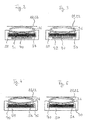
- Fig. 2 shows an embodiment in which the sealing means 70 has a plate-like shape.
- the sealing means 70 is arranged parallel to the plate-shaped sliding element 56.
- the sealing means 70 is located on a side opposite the elastic element 36 side of the sliding element 56.
- the sealing means 70 is connected to the guide foot 50 against displacement.
- the sliding element 56 is displaceably mounted along the sealing means 70. Rail-like projections of the sliding element 56 engage in corresponding recesses or grooves of the sealing means 70.
- Fig. 3 shows a further embodiment of a sealant 70.
- the sealing means 70 has at least one protruding sealing part, which engages in a corresponding groove-like or groove-like depression of the sliding element 56.
- three protruding sealing parts are provided.
- FIGS. 4 and 5 show further embodiments of sealing means 70.
- two sealing means 70 are provided, which are each arranged in a space between the guide foot 50 and the sliding element 56.
- the sealing means 70 are arranged opposite one another on the side of the plate-shaped sliding element 56 and in each case are fastened to the guide foot 50.
- the sliding element 56 is slidably guided along the sealing means 70.
- the sealing means 70 have a substantially semicircular shape.
- FIG. 5 The embodiment shown differs from the embodiment according to FIG Fig. 4 in that the sealing means 70 are fastened to longitudinal edges of the sliding element 56.
- the sliding element is displaceably or slidably mounted on the guide foot 50 via the sealing means 70.
- a plastering strip is provided, which allows a reliable and clean completion of a plaster layer and also provides an appealing conclusion of a plaster layer.
Landscapes
- Engineering & Computer Science (AREA)
- Architecture (AREA)
- Civil Engineering (AREA)
- Structural Engineering (AREA)
- Mechanical Engineering (AREA)
- Specific Sealing Or Ventilating Devices For Doors And Windows (AREA)
- Building Environments (AREA)
Description
Die Erfindung betrifft eine Anputzleiste nach dem Oberbegriff des Anspruchs 1. Eine solche Anputzleiste weist einen Profilkörper, einen Führungsfuß und eine Basisfläche an dem Führungsfuß zum Anlegen der Anputzleiste an ein Gebäudeelement, insbesondere einen Tür- oder Fensterstock, auf.The invention relates to a plaster molding according to the preamble of claim 1. Such a plaster molding has a profile body, a guide foot and a base surface on the guide foot for applying the plaster molding to a building element, in particular a door or window stock.
Bekannte Anputzleisten gehen jeweils aus der
Eine gattungsgemäße Anputzleiste geht beispielsweise aus der
Die Verwendung einer Anputzleiste erfolgt üblicherweise folgendermaßen: Die Anputzleiste wird zunächst mittels einer Klebeschicht in einem Eckbereich zwischen dem Tür- oder Fensterstock und einem angrenzenden Wandabschnitt auf den Tür- oder Fensterstock aufgeklebt. Anschließend erfolgt der Auftrag einer oder mehrerer Putzschichten auf den WandabschnittThe use of a plaster strip is usually carried out as follows: The plaster strip is first glued by means of an adhesive layer in a corner between the door or window floor and an adjacent wall section on the door or window floor. Subsequently, one or more plaster layers are applied to the wall section
Der Erfindung liegt die Aufgabe zugrunde, eine Anputzleiste der angegebenen Art so zu verbessern, dass diese einen möglichst zuverlässigen und sauberen Abschluss einer Putzschicht ermöglicht.The invention has for its object to improve a plaster molding of the specified type so that this allows the most reliable and clean completion of a plaster layer.
Die Aufgabe wird durch eine Anputzleiste mit den Merkmalen des Anspruchs 1 gelöst. Vorteilhafte Ausgestaltungen sind in den abhängigen Ansprüchen, der Beschreibung sowie den Figuren angegeben.The object is achieved by a plaster molding with the features of claim 1. Advantageous embodiments are specified in the dependent claims, the description and the figures.
Die erfindungsgemäße Anputzleiste ist dadurch gekennzeichnet, dass zum Abdichten eines Zwischenraumes zwischen dem Führungsfuß und dem Profilkörper ein Dichtelement vorgesehen ist, welches mit dem Profilkörper und/oder dem Führungsfuß verbunden ist.The plaster strip according to the invention is characterized in that for sealing an intermediate space between the guide foot and the profile body a Sealing element is provided, which is connected to the profile body and / or the guide foot.
Ein Grundgedanke der Erfindung besteht darin, den Profilkörper gegenüber dem Führungsfuß abzudichten, um ein Eindringen von Feuchtigkeit, insbesondere in Form von Starkregen, in einen Spalt zwischen dem Profilkörper und dem Führungsfuß möglichst zu verhindern. Hierdurch wird zugleich verhindert, dass Feuchtigkeit durch den Zwischenraum zwischen Führungsfuß und Profilkörper hinter die Anputzleiste gelangen und so den Putz beschädigen kann.A basic idea of the invention is to seal the profiled body with respect to the guide foot in order to prevent penetration of moisture, in particular in the form of heavy rain, into a gap between the profiled body and the guide foot as far as possible. This also prevents moisture from getting through the gap between the guide foot and profile body behind the plaster molding and can damage the plaster.
Das Dichtelement ist dabei vorzugsweise so gestaltet und angeordnet, dass ein Spalt zwischen Führungsfuß und Profilkörper von außen abgedeckt wird. Hierdurch wird zum einen eine gute Abdichtung und zum anderen ein optisch ansprechender Abschluss der Putzschicht erzielt. Das Dichtelement weist vorzugsweise eine äußere weitgehend glatte, also nicht gewellte oder gefaltete, Oberfläche auf, durch welche eine Anlagerung von Feuchtigkeit weitgehend unterbunden werden kann.The sealing element is preferably designed and arranged so that a gap between the guide foot and profile body is covered from the outside. As a result, on the one hand a good seal and on the other hand a visually appealing conclusion of the plaster layer is achieved. The sealing element preferably has an outer surface which is largely smooth, ie not corrugated or folded, by means of which an accumulation of moisture can be largely prevented.
Der Profilkörper ist insbesondere in einer Längsrichtung der Anputzleiste entlang des Führungsfußes verschiebbar. Hierdurch wird eine Bewegung des Profilkörpers gegenüber dem Gebäudeelement, insbesondere parallel zu einer Gebäudeoberfläche, möglich. Somit können Verschiebungen beispielsweise zwischen einem Tür- oder Fensterstock und einem angrenzenden Wandabschnitt, wie sie beispielsweise durch Temperaturschwankungen, Windlasten oder Stoßbelastungen, wie durch Fensterzuschlagen, hervorgerufen werden können, ausgeglichen werden.The profile body is displaceable in particular in a longitudinal direction of the plastering strip along the guide foot. As a result, a movement of the profile body relative to the building element, in particular parallel to a building surface, possible. Thus, displacements can be compensated, for example, between a door or window stock and an adjacent wall portion, such as may be caused by temperature variations, wind loads or impact loads, such as window slamming.
Ein weiterer Grundgedanke der Erfindung besteht darin, dass das Dichtelement eine Abdichtung auch bei einer Bewegung des Profilkörpers gegenüber dem Führungsfuß, insbesondere einer Längsverschiebung gegenüber dem Führungsfuß, gewährleistet. Hierzu ist es vorteilhaft, wenn das Dichtelement gegenüber dem Führungsfuß und/oder dem Profilkörper bewegbar ist. Besonders bevorzugt ist es, wenn das Dichtelement fest mit dem Profilkörper oder dem Führungsfuß verbunden ist und gegenüber oder entlang dem jeweils anderen Element bewegbar oder verschiebbar ist.Another basic idea of the invention is that the sealing element ensures a seal even with a movement of the profile body relative to the guide foot, in particular a longitudinal displacement relative to the guide foot. For this purpose, it is advantageous if the sealing element is movable relative to the guide foot and / or the profile body. It is particularly preferred if the sealing element is firmly connected to the profile body or the guide foot and is movable or displaceable with respect to or along the respective other element.
Eine bevorzugte Ausgestaltung ist dadurch gegeben, dass das Dichtelement stoffschlüssig, insbesondere durch Koextrusion, an dem Führungsfuß und/oder dem Profilkörper befestigt ist. Das Dichtelement kann aus einem anderen Material hergestellt sein als der Führungsfuß und/oder der Profilkörper. Durch die Koextrusion ist das Dichtelement fest und dicht mit dem Führungsfuß und/oder dem Profilkörper verbunden sein. Die Koextrusion stellt ein besonders wirtschaftliches Verfahren dar.A preferred embodiment is given by the fact that the sealing element is firmly bonded, in particular by coextrusion, to the guide foot and / or the profile body. The sealing element can be made of a different material be as the guide foot and / or the profile body. By coextrusion, the sealing element is fixed and tightly connected to the guide foot and / or the profile body. Coextrusion is a particularly economical process.
Weiterhin ist es bevorzugt, dass das Dichtelement unter Vorspannung an dem Führungsfuß und/oder dem Profilkörpers anliegt. Das Dichtelement ist vorzugsweise gegenüber dem Führungsfuß und/oder dem Profilkörper bewegbar, so dass im Zusammenspiel mit der Vorspannung eine gute Dichtwirkung selbst bei einer Bewegung des Profilkörpers gegenüber dem Führungsfuß erzielt werden kann.Furthermore, it is preferred that the sealing element bears under pretension on the guide foot and / or the profile body. The sealing element is preferably movable relative to the guide foot and / or the profile body, so that in conjunction with the bias a good sealing effect can be achieved even with a movement of the profile body relative to the guide foot.
Eine bevorzugte Ausführungsform besteht darin, dass das Dichtelement stoffschlüssig mit dem Führungsfuß verbunden ist und unter Vorspannung an dem Profilkörper anliegt. Das Dichtelement, welches auch als Dichtlippe bezeichnet werden kann, ist an dem Führungsfuß stoffschlüssig durch Koextrusion befestigt. Die Dichtlippe ist dabei so anextrudiert, dass sie im mit dem Profilkörper verbundenen Zustand unter Vorspannung an dem Profilkörper anliegt.A preferred embodiment is that the sealing element is integrally connected to the guide foot and bears under pretension on the profile body. The sealing element, which may also be referred to as a sealing lip, is fastened to the guide foot in a material-locking manner by coextrusion. The sealing lip is extruded so that it rests in the connected to the profile body state under bias to the profile body.
Grundsätzlich kann das Dichtelement aber auch mit dem Profilkörper stoffschlüssig verbunden sein und unter Vorspannung an dem Führungsfuß anliegen.In principle, however, the sealing element can also be materially connected to the profile body and rest under pretension on the guide foot.
Neben der Abdichtung des Profilkörpers gegenüber dem Führungsfuß dient das Dichtelement im Montagezustand vorzugsweise auch der Abdichtung des Führungsfußes gegenüber einer Anlagefläche des Gebäudeelements, an welche die Anputzleiste mit ihrer Basisfläche angelegt werden kann. Hierzu weist das Dichtelement eine Kontaktfläche auf, welche in Verlängerung der Basisfläche des Führungsfußes angeordnet ist. Das Dichtelement kann demnach so gestaltet sein, dass es im Montagezustand an der Anlagefläche anliegt. Vorzugsweise liegt das Dichtelement dabei im Wesentlichen flächig an der Anlagefläche an.In addition to the sealing of the profile body relative to the guide foot, the sealing element in the assembled state preferably also serves to seal the guide foot with respect to a contact surface of the building element to which the plastering strip can be applied with its base surface. For this purpose, the sealing element has a contact surface, which is arranged in extension of the base surface of the guide foot. The sealing element can therefore be designed so that it rests in the assembled state of the contact surface. Preferably, the sealing element is in this case substantially flat against the contact surface.
Eine Außenkontur des Dichtelements kann konkav geformt sein, so dass ein im Wesentlichen kontinuierlicher Übergang von der Anlagefläche zu einer Außenfläche eines äußeren Einputzsteges, ähnlich einer bekannten Silikonfuge, bereitgestellt werden kann. Vorzugsweise ist das Dichtelement so gestaltet, dass es im Montagezustand unter Vorspannung an der Anlagefläche anliegt.An outer contour of the sealing element may be concave-shaped, so that a substantially continuous transition from the abutment surface to an outer surface of an outer Einputzsteges, similar to a known silicone joint, can be provided. Preferably, the sealing element is designed so that it rests in the assembled state under pretension on the contact surface.
Das Dichtelement kann zumindest bereichsweise lamellen- und/oder bogenförmig gestaltet sein. Hierdurch kann auf zweckmäßige Weise eine Dichtlippe bereitgestellt werden, die unter Vorspannung an dem Führungsfuß und/oder dem Profilkörper anliegen kann. Gleichzeitig wird eine ansprechende Form des Dichtelements bereitgestellt.The sealing element may be designed at least partially lamellar and / or arcuate. In this way, a sealing lip can be provided in an expedient manner, which can rest under prestress on the guide foot and / or the profile body. At the same time, an attractive shape of the sealing element is provided.
Eine weitere bevorzugte Ausführungsform besteht darin, dass eine Dicke des Dichtelements in Richtung des Führungsfußes hin zunimmt. Hierdurch kann das Dichtelement in einem unteren Bereich in Form einer üblichen Silikonfuge gestaltet sein und damit einen besonders ansprechenden optischen Abschluss bereitstellen. Als unterer Bereich wird hierbei insbesondere ein Bereich verstanden, der an eine Ebene der Basisfläche angrenzt.A further preferred embodiment consists in that a thickness of the sealing element increases in the direction of the guide foot. In this way, the sealing element can be designed in a lower region in the form of a conventional silicone joint and thus provide a particularly attractive optical termination. In this case, a lower region is understood in particular to be a region which adjoins a plane of the base surface.
In einer bevorzugten Ausgestaltung weist der Profilkörper ein elastisches Element und ein Schiebeelement auf. Das Schiebelement ist entlang des Führungsfußes, welcher auch als Führungsschuh bezeichnet werden kann, verschiebbar gelagert. Das elastische Element ist zwischen dem Schiebeelement und einem Basissteg des Profilkörpers angeordnet. Das elastische Element kann grundsätzlich so gestaltet sein, dass es Bewegungen oder Translationen des Profilkörpers gegenüber dem Führungsfuß beziehungsweise dem Schiebeelement in alle Raumrichtungen ermöglicht.In a preferred embodiment, the profile body has an elastic element and a sliding element. The sliding element is slidably mounted along the guide foot, which can also be referred to as a guide shoe. The elastic element is arranged between the sliding element and a base web of the profile body. The elastic element can in principle be designed so that it allows movements or translations of the profile body relative to the guide foot or the sliding element in all spatial directions.
Insbesondere ist vorgesehen, dass durch das elastische Element zusätzlich zu der durch den Führungsfuß und das Schiebeelement bereitgestellten Längsverschiebbarkeit des Profilkörpers eine Bewegung des Profilkörpers quer zur Längsachse ermöglicht wird. Durch das Schiebeelement und das elastische Element wird dann insgesamt eine Bewegung des Profilkörpers gegenüber dem Führungsfuß in alle Raumrichtungen ermöglicht, wodurch ein besonders guter Ausgleich von Kräften erzielt werden kann. Die Anputzleiste kann insbesondere in einer Normalen zu der Anlagefläche, also einem Baukörper beziehungsweise dem Fenster- oder Türrahmen, sowohl Druck- als auch Zugkräfte aufnehmen und ermöglicht weiterhin eine seitliche Verschiebung entlang des Baukörpers.In particular, it is provided that, in addition to the longitudinal displaceability of the profile body provided by the guide foot and the sliding element, a movement of the profile body transversely to the longitudinal axis is made possible by the elastic element. By the sliding element and the elastic element, a total movement of the profile body relative to the guide foot in all spatial directions is made possible, whereby a particularly good balance of forces can be achieved. The screed can absorb both compressive and tensile forces, in particular in a normal to the contact surface, so a building or the window or door frame and also allows a lateral displacement along the structure.
Das elastische Element ist schlauchförmig ausgebildet. Es ermöglicht damit insbesondere Translationen in der Normalen zum Baukörper und in einer zum Baukörper parallelen Ebene quer zur Längsachse des Profilkörpers, üblicherweise in Richtung eines Fensters beziehungsweise einer Tür.The elastic element is tubular. It thus allows in particular translations in the normal to the building and in a Building parallel plane transverse to the longitudinal axis of the profile body, usually in the direction of a window or a door.
Zur Beweglichkeit entlang einer dritten Raumrichtung, der Längsrichtung der Anputzleiste, ist insbesondere die verschiebbare Führung entlang des Führungsfußes vorgesehen.For mobility along a third spatial direction, the longitudinal direction of the plastering strip, in particular the displaceable guide along the guide foot is provided.
Insbesondere zur weiteren Abdichtung ist es bevorzugt, dass das Dichtelement mindestens ein Dichtmittel zwischen dem Führungsfuß und einem Schiebeelement des Profilkörpers aufweist. Grundsätzlich kann das Dichtmittel auch anstelle des Dichtelements vorgesehen sein.In particular, for further sealing, it is preferred that the sealing element has at least one sealing means between the guide foot and a sliding element of the profile body. In principle, the sealing means may also be provided instead of the sealing element.
Vorzugsweise ist das Dichtmittel in einer rinnenförmigen Aussparung in dem Führungsfuß angeordnet. Dies ermöglicht eine besonders gute Abdichtung und zugleich eine gute Bewegbarkeit des Schiebeelements entlang des Führungsfußes.Preferably, the sealing means is arranged in a groove-shaped recess in the guide foot. This allows a particularly good seal and at the same time a good mobility of the sliding element along the guide foot.
Eine weitere Möglichkeit besteht darin, dass an zwei gegenüberliegenden Seiten des Schiebeelements jeweils mindestens ein Dichtmittel angeordnet ist. Die Dichtmittel sind vorzugsweise so ausgeführt, dass ebenfalls eine gute Bewegbarkeit des Schiebeelements erzielt wird. Hierzu sind die Dichtmittel an Längsseiten, insbesondere schmalen, des Schiebelements angeordnet.Another possibility is that at least one sealing means is arranged on two opposite sides of the sliding element. The sealing means are preferably designed so that also a good mobility of the sliding element is achieved. For this purpose, the sealing means are arranged on longitudinal sides, in particular narrow, of the sliding element.
Die Erfindung wird nachfolgend anhand der beigefügten schematischen Zeichnungen weiter erläutert. In diesen zeigt:
- Fig. 1
- eine erste Ausführungsform einer Anputzleiste;
- Fig. 2
- eine Detailansicht einer ersten Ausführungsform des Führungsfußes;
- Fig. 3
- eine Detailansicht einer zweiten Ausführungsform des Führungsfußes;
- Fig. 4
- eine Detailansicht einer dritten Ausführungsform des Führungsfußes;
- Fig. 5
- eine Detailansicht einer vierten Ausführungsform des Führungsfußes.
- Fig. 1
- a first embodiment of a plastering strip;
- Fig. 2
- a detailed view of a first embodiment of the guide foot;
- Fig. 3
- a detailed view of a second embodiment of the guide foot;
- Fig. 4
- a detailed view of a third embodiment of the guide foot;
- Fig. 5
- a detailed view of a fourth embodiment of the guide foot.
Die Anputzleiste 10 weist eine Basisfläche 12 auf, entlang welcher die Anputzleiste 10 an ein Gebäudeelement, insbesondere an einen Tür- oder Fensterstock oder eine Rolloschiene, angelegt werden kann. Die entsprechende Fläche des Gebäudeelements, an welche die Anputzleiste 10 in einem Montagezustand angelegt ist, wird im Folgenden als Anlagefläche bezeichnet. Bei der Anlagefläche handelt es sich vorzugsweise um eine ebene, im Montagezustand der Anputzleiste 10 zur Basisfläche 12 parallele Fläche. Insbesondere ist hierunter eine Fläche zu verstehen, die in einer Ebene mit der Basisfläche 12 der Anputzleiste 10 verläuft.The
Die Anputzleiste 10 wird im Montagezustand vorzugsweise an der Anlagefläche befestigt. Hierzu weist die Basisfläche 12 eine Klebeschicht 14 auf, so dass die Anputzleiste 10 an die Anlagefläche angeklebt werden kann. Die Klebeschicht 14 kann beispielsweise ein doppelseitiges Klebeband sein, welches an einer Grundfläche 11 der Anputzleiste 10 angeklebt ist. Grundsätzlich können auch mehrere Klebeschichten 14 oder Klebeelemente vorgesehen sein.The
Die Anputzleiste 10 weist ferner einen Basissteg 22 auf. Der Basissteg 22 weist eine Längsachse auf, die sich in Längsrichtung der Anputzleiste 10 erstreckt. Eine Ebene des Basisstegs 22 ist im Wesentlichen parallel zur Basisfläche 12 und/oder zur Grundfläche 11 ausgerichtet.The
Die Anputzleiste 10 umfasst ferner drei Einputzstege 24, 26, 30, welche sich im Wesentlichen quer zu dem Basissteg 22 erstrecken. Die Einputzstege 24, 26, 30 weisen ebenfalls eine Längsachse auf, die parallel zu einer Längsachse der Anputzleiste 10 verläuft. Vorzugsweise sind an der Anputzleiste 10 mehrere Einputzstege 24, 26, 30, insbesondere zwei oder drei Einputzstege 24, 26, 30, vorgesehen. Verallgemeinert weißt die Anputzleiste 10 mindestens einen Einputzsteg 24, 26, 30 auf. Der Basissteg 22 und der oder die Einputzstege 24, 26, 30 bilden einen Profilrahmen des Profilkörpers 20.The
Das in
Der äußere Einputzsteg 30 ist nach Fertigstellung der Putzarbeiten üblicherweise im Wesentlichen entlang einer äußeren Oberfläche einer Putzschicht angeordnet. Der innere Einputzsteg 24 ist insbesondere dazu vorgesehen, die Anputzleiste 10 an eine Gebäudefläche, insbesondere eine zu einer Tür- oder Fensterfläche quer angeordnete Gebäudefläche, anzulegen. Er kann dementsprechend auch als Anlagesteg bezeichnet werden. Der äußere Einputzsteg 20 weist eine größere Breite auf als der innere Einputzsteg 24.The
Der mittlere Einputzsteg 26 ist zwischen dem inneren Einputzsteg 24 und dem äußeren Einputzsteg 30 angeordnet und dient dazu, eine Abzugsfläche für eine erste, innere Putz- oder Spachtelschicht bereitzustellen. Hierzu ist an dem mittleren Einputzsteg 26 vorzugsweise ein Vorsprung 27 vorgesehen, der eine Abzugskante 28 bildet. Der Vorsprung 27 erstreckt sich in Richtung des äußeren Einsputzsteges 30, so dass zwischen dem mittleren Einputzsteg 26 und dem äußeren Einputzsteg 30 eine Hinterschneidung 29 gebildet ist. Grundsätzlich kann auch mindestens einer der Einputzstege 24, 26, 30 weggelassen oder ein weiterer Einputzsteg hinzugefügt werden.The
An einem der Einputzstege, insbesondere dem mittleren Einputzsteg 26, kann ein Gewebe 32, Gewirk oder Ähnliches befestigt sein. Eine bevorzugte Art der Befestigung eines solchen Gewebes 32 oder Ähnlichem mit dem Profilkörper 20 beziehungsweise dem Profilrahmen besteht darin, einen zwischen zwei Einputzstegen, insbesondere dem inneren Einputzsteg 24 und dem mittleren Einputzsteg 26, gebildeten Bereich mit einem Füllelement 34 oder Füllmaterial auszufüllen. Dieser Bereich ist üblicherweise kanal- oder rinnenförmig gestaltet. Das Füllelement 34 fixiert das Gewebe 32 an einem der Einputzstege, insbesondere dem inneren Einputzsteg 24 oder dem mittleren Einputzsteg 26. Vorzugsweise wird das Füllelement 34 mit dem Profilkörper 20 koextrudiert.At one of the Einputzstege, in particular the
Das Gewebe 32, welches auch als Armierungsgewebe bezeichnet werden kann, kann in bekannter Weise Durchbrechungen in Form eines Lochprofils aufweisen. Der Putz durchdringt das Gewebe 32 durch das Lochprofil, wodurch eine gute Verbindung mit der Gebäudewand hergestellt wird.The
An dem Profilkörper 20 ist weiterhin eine Schutzlasche 38 angeordnet. Die Schutzlasche erstreckt sich im Montagezustand in Richtung der Tür- oder Fensterfläche. Die Schutzlasche 38 ist so mit dem Profilkörper 20 verbunden, dass die Schutzlasche 38 definiert von dem Profilkörper 20 abtrennbar ist. Nach Beendigung der Verputzarbeiten kann die Schutzlasche 38, vorzugsweise zusammen mit einer daran befestigten Schutzfolie, von dem Profilkörper 20 abgetrennt werden. Hierzu ist beispielsweise zwischen dem Profilkörper 20 und der Schutzlasche 38 eine Sollbruchstelle, insbesondere in Form einer Materialschwächung, vorgesehen. Dies kann beispielsweise durch eine Materialverdünnung am Übergang zwischen Profilkörper 20 und Schutzlasche 38 erfolgen. Die Schutzlasche 38 ist vorzugsweise an einem Einputzsteg, insbesondere dem äußeren Einputzsteg 30, des Profilkörpers 20 befestigt. Die Schutzlasche 38 kann an der Sollbruchstelle elastisch mit dem Profilkörper 20, insbesondere dem Einputzsteg 30, verbunden sein. Die Schutzlasche 38 kann auch als Abreißlasche bezeichnet werden. Die Seite des Profilkörpers 20, an welcher die Schutzlasche 38 angeordnet ist, wird auch als äußere Seite des Profilkörpers 20 bezeichnet.On the profile body 20 a
An der Schutzlasche kann eine Schutzfolie zum Schutz der Tür- oder Fensterfläche angebracht werden. Die Schutzlasche 38 weist hierzu ein Klebeelement 48 oder eine Klebeschicht auf. Das Klebeelement 48 kann beispielsweise ein Klebeband, insbesondere ein doppelseitiges Klebeband, sein. Das Klebeelement 48 beziehungsweise die Klebeschicht ist auf einer Seite der Schutzlasche 38 vorgesehen, die im Montagezustand der Anputzleiste 10 der Anlagefläche des Gebäudeelements abgewandt ist.On the protective flap, a protective film to protect the door or window surface can be attached. The
Die Schutzlasche 38 weist eine im Wesentlichen gerade Form auf und ist etwa parallel zur Basisfläche 12 ausgerichtet. Die Schutzlasche 38 weist vorzugsweise eine im Wesentlichen gleichbleibende Dicke oder Stärke auf.The
Die Anputzleiste 10 weist einen Führungsfuß 50 und ein plattenförmiges Schiebeelement 56 auf, welches an dem Führungsfuß 50 entlang einer Längsachse der Anputzleiste 10 verschiebbar geführt ist. Der Profilkörper 20 beziehungsweise der Profilrahmen ist mit dem Schiebeelement 56 verbunden und so über das Schiebeelement 56 gegenüber oder entlang des Führungsfußes 50 verschiebbar gelagert. Durch die verschiebbare Lagerung des Profilkörpers 20 können Kräfte in einer Längsrichtung der Anputzleiste 10 kompensiert werden.The
Die Basisfläche 12 und die Klebeschicht 14 sind an dem Führungsfuß 50 der Anputzleiste 10 angeordnet. Der Führungsfuß 50 kann als steg- oder plattenförmiges Element ausgebildet sein, welches sich parallel zu dem Basissteg 22 des Profilkörpers 20 erstreckt. Zur Führung des Schiebeelementes 56 beziehungsweise des Profilkörpers 20 entlang des Führungsfußes 50 weist der Führungsfuß seitliche Führungsschienen 58 auf. Die Führungsschienen 58 weisen jeweils einen Vorsprung 57 auf, welcher das Schiebelement 56 umgreift.The
Um auch Kräfte quer beziehungsweise in der Normalen zur Basisfläche 12 kompensieren zu können, ist ein elastisches Element 36 vorgesehen. Das elastische Element 36 ist zwischen dem Schiebeelement 56 und dem Profilkörper 20, insbesondere dem Basissteg 22, angeordnet. Der Profilkörper 20 beziehungsweise der Profilrahmen ist über das elastische Element 36 mit dem Schiebeelement 56 verbunden.In order to be able to compensate for forces transversely or in the normal to the
Das elastische Element 36 ist vorzugsweise aus einem weich-elastischen oder flexiblen Material, insbesondere einem weichen Kunststoff, gebildet und dient dazu, den Profilkörper 20 beziehungsweise den Profilrahmen gegenüber dem Schiebeelement 56 elastisch bewegbar zu lagern. Damit wird der Profilkörper 20 auch gegenüber dem Führungsfuß 50 beziehungsweise der Anlagefläche des Gebäudeelements bewegbar gelagert. Das elastische Element 36 beinhaltet vorzugsweise ein anderes Material als der Profilkörper 20 und/oder das Schiebeelement 56 und kann mit dem Profilkörper 20 und/oder dem Schiebeelement 56 koextrudiert sein. Der Profilkörper 20 ist vorzugsweise aus einem harten Material, insbesondere Kunststoff, gebildet.The
Zusammen mit dem elastischen Element 36 kann die Anputzleiste 10 so Kräfte in allen drei Dimensionen kompensieren. Die Basisfläche 12 zum Anlegen der Anputzleiste 10 an das Gebäudeelement ist vorzugsweise an dem Führungsfuß 50 vorgesehen. Zum Festkleben der Anputzleiste 10 an der Anlagefläche eines Gebäudeelements weist die Basisfläche 12 eine Klebeschicht 14 auf.Together with the
Das elastische Element 36 ist vorzugsweise etwa schlauch- oder schlaufenförmig geformt. Es weist beispielsweise einen kreisförmigen, ovalen und/oder ellipsenförmigen Querschnitt auf. Diese Ausgestaltung ermöglicht eine abrollartige Bewegung des Profilkörpers gegenüber dem Befestigungselement 16. Grundsätzlich sind aber auch andere Formen eines elastischen Elements 36 möglich. Auch können mehrere elastische Elemente 36 vorgesehen sein.The
Zum Abdichten eines Zwischenraumes zwischen dem Führungsfuß 50 und dem Profilkörper 20 ist ein Dichtelement 60 vorgesehen. Das Dichtelement 60 kann die Form einer Dichtlippe aufweisen. Vorzugsweise ist das Dichtelement 60 mit dem Führungsfuß 50 stoffschlüssig verbunden. Hierzu kann das Dichtelement 60 an den Führungsfuß 50 anextrudiert sein, was vorzugsweise durch Koextrusion erfolgt. Das Dichtelement 60 enthält ein elastisches Material, insbesondere einen weichen Kunststoff.For sealing a gap between the
Eine äußere Oberfläche des Dichtelements 60 weist eine gebogene, insbesondere eine konkave Form auf. Das Dichtelement 60 ist so gestaltet, dass es nicht nur einen Zwischenraum zwischen dem Führungsfuß 50 und dem Profilkörper 20, sondern im Montagezustand der Anputzleiste 10 auch den Führungsfuß 50 gegenüber der Anlagefläche abdichtet. Hierzu weist das Dichtelement 60 einen ersten Bereich auf, der an der Anlagefläche anlegbar ist. In der dargestellten Ausführungsform weist das Dichtelement hierzu eine Kontaktfläche 62 auf, die im Wesentlichen parallel zur Basisfläche 12 verläuft, so dass das Dichtelement 60 im Wesentlichen flächig an der Anlagefläche anlegbar ist.An outer surface of the sealing
Ein zweiter Bereich des Dichtelements 60 liegt an dem Profilkörper 20, insbesondere dem äußeren Einputzsteg 30, an. Das Dichtelement 60 liegt vorzugsweise sowohl an dem Profilkörper 20 als auch im Montagezustand an der Anlagefläche unter Vorspannung an. Das Dichtelement 60 kann verhindern, dass Feuchtigkeit, insbesondere durch Schlagregen, hinter die Anputzleiste 10 dringt und den Putz beschädigt.A second region of the sealing
Eine besonders dichte Abdichtung des Führungsfußes 50 gegenüber dem Profilkörper 20 kann dadurch erreicht werden, dass zusätzlich oder alternativ zu dem Dichtelement 60 zwischen dem Schiebeelement 56 und dem Führungsfuß 50 mindestens ein weiteres Dichtmittel 70 (
Eine bevorzugte Ausführungsform besteht darin, dass das Dichtmittel 70 in einer Aussparung 72 des Führungsfußes 50 angeordnet ist, wie in
Die in
Mit der Erfindung wird eine Anputzleiste bereitgestellt, die einen zuverlässigen und sauberen Abschluss einer Putzschicht ermöglicht und zudem einen ansprechenden Abschluss einer Putzschicht bereitstellt.With the invention, a plastering strip is provided, which allows a reliable and clean completion of a plaster layer and also provides an appealing conclusion of a plaster layer.
Claims (11)
- Plastering strip having- a profile body (20),- a guide foot (50) and- a base surface (12) on the guide foot (50) for applying the plastering strip (10) to a building element, in particular a door or window frame,wherein the profile body (20) has a slide element (56), with which the profile body (20) is supported in a displaceable manner with respect to the guide foot (50) in a longitudinal direction of the profile body (20), and
wherein between the slide element (56) and a base bar (22) of the profile body (20) an elastic element (36) is arranged, through which movability in a direction transverse to the longitudinal direction is provided,
characterized in that
the elastic element (36) is designed in a hose-shaped manner and
in that for the sealing of an intermediate space between the guide foot (50) and the profile body (20) a sealing element (60, 70) is provided which is connected to the profile body (20) and/or the guide foot (50). - Plastering strip according to claim 1,
characterized in that
the sealing element (60, 70) is fixed in a material-bonding manner, in particular through coextrusion, on the guide foot (50) and/or the profile body (20). - Plastering strip according to any one of claims 1 or 2,
characterized in that
the sealing element (60, 70) rests under pre-tension against the guide foot (50) and/or the profile body (20). - Plastering strip according to any one of claims 1 to 3,
characterized in that
the sealing element (60, 70) has a contact surface (62) which is arranged in the extension of the base surface (12) of the guide foot (50). - Plastering strip according to any one of claims 1 to 4,
characterized in that
in at least some areas the sealing element (60, 70) is of lamellar and/or arched design. - Plastering strip according to any one of claims 1 to 5,
characterized in that
a thickness of the sealing element (60, 70) increases in the direction of the guide foot (50). - Plastering strip according to any one of claims 1 to 6,
characterized in that
the elastic element (36) is formed of a soft-elastic or flexible material, preferably of a softer plastic than the plastic of the profile body (20). - Plastering strip according to any one of claims 1 to 7,
characterized in that
the sealing element (60, 70) is designed as a sealing lip. - Plastering strip according to any one of claims 1 to 8,
characterized in that
the sealing element (60, 70) has at least one sealant (70) between the guide foot (50) and the slide element (56) of the profile body (20). - Plastering strip according to claim 9,
characterized in that
the sealant (70) is arranged in a trough-shaped recess (72) in the guide foot (50). - Plastering strip according to claim 9 or 10,
characterized in that
on two opposite sides of the slide element (56) at least one sealant (70) is arranged in each case.
Applications Claiming Priority (2)
| Application Number | Priority Date | Filing Date | Title |
|---|---|---|---|
| DE201020004621 DE202010004621U1 (en) | 2010-04-06 | 2010-04-06 | plastering strip |
| DE102010031929A DE102010031929A1 (en) | 2010-04-06 | 2010-07-22 | plastering strip |
Publications (3)
| Publication Number | Publication Date |
|---|---|
| EP2374961A2 EP2374961A2 (en) | 2011-10-12 |
| EP2374961A3 EP2374961A3 (en) | 2013-12-18 |
| EP2374961B1 true EP2374961B1 (en) | 2017-06-07 |
Family
ID=44259793
Family Applications (1)
| Application Number | Title | Priority Date | Filing Date |
|---|---|---|---|
| EP11161136.4A Active EP2374961B1 (en) | 2010-04-06 | 2011-04-05 | Plastering strip |
Country Status (2)
| Country | Link |
|---|---|
| EP (1) | EP2374961B1 (en) |
| DE (1) | DE102010031929A1 (en) |
Families Citing this family (2)
| Publication number | Priority date | Publication date | Assignee | Title |
|---|---|---|---|---|
| DE202013002941U1 (en) | 2013-03-26 | 2013-05-02 | Weroform Gmbh | plastering strip |
| AT519110B1 (en) * | 2017-04-28 | 2018-04-15 | AF Tec Beteiligungs GmbH | CONNECTION PROFILE FOR COMPONENTS TO BE ADJUSTED TO PUTZ |
Family Cites Families (4)
| Publication number | Priority date | Publication date | Assignee | Title |
|---|---|---|---|---|
| DE19819605B4 (en) * | 1998-05-02 | 2008-08-14 | Protektorwerk Florenz Maisch Gmbh & Co Kg | End strip for sealing a frame part relative to a soffit |
| DE19923309A1 (en) * | 1999-03-08 | 2000-09-14 | Lorentz Doris | Profile bar |
| DE102006002054A1 (en) * | 2006-01-16 | 2007-07-19 | Konrad Lehrhuber | Sealing arrangement and profile strip for a sealing arrangement |
| DE202008006053U1 (en) | 2008-05-02 | 2008-09-18 | E. Woerner Gmbh & Co. Kg | Connection profile, in particular plaster connection profile |
-
2010
- 2010-07-22 DE DE102010031929A patent/DE102010031929A1/en not_active Withdrawn
-
2011
- 2011-04-05 EP EP11161136.4A patent/EP2374961B1/en active Active
Also Published As
| Publication number | Publication date |
|---|---|
| EP2374961A2 (en) | 2011-10-12 |
| DE102010031929A1 (en) | 2011-10-06 |
| EP2374961A3 (en) | 2013-12-18 |
Similar Documents
| Publication | Publication Date | Title |
|---|---|---|
| EP1811111B1 (en) | Window opening with a window frame and a sealing strip | |
| EP2834095B1 (en) | Profile element for connecting a vehicle disc to a cover part and profile element assembly | |
| EP2492428B3 (en) | Staff angle and building corner with staff angle | |
| EP2586952B2 (en) | Gate with provisions for insulation | |
| EP2784259B1 (en) | Plastering profile | |
| EP1674649B1 (en) | Two-part connecting section for plaster adjoining construction elements | |
| EP3034768B1 (en) | Window or door with a glazing rebate adhesive | |
| EP2666948A1 (en) | Frame assembly for a panel for sectional doors | |
| EP2754842B1 (en) | Sealing profile for a frame profile and frame profile | |
| EP2374961B1 (en) | Plastering strip | |
| EP0421316B1 (en) | Lockable sealing and filling joint, especially for vehicle windows | |
| DE7406930U (en) | PROFILED GUIDE BAR FOR THE MOUNTING AND GUIDING OF A WINDOW PANEL IN THE FRAMEWORK OF A VEHICLE DOOR | |
| EP2273037A2 (en) | Plastering strip | |
| EP3037617B1 (en) | Plastering strip with support feet | |
| AT501438A1 (en) | LOCATION CONNECTION PROFILE FOR COMPONENTS TO BE ADJUSTED TO PUTZ | |
| AT413293B (en) | SLIDING ELEMENT SEAL | |
| DE102017005236A1 (en) | Vehicle door with height-adjustable window | |
| AT404965B (en) | GLASS FOLDED GASKET, ESPECIALLY FOR WINDOWS AND DOORS | |
| EP3569807B1 (en) | Joint covering profile | |
| EP3574176B1 (en) | Guide rail for guiding roller shutters, sun screens or similar, and a method for its manufacturing | |
| AT16012U1 (en) | plastering strip | |
| EP2492429A2 (en) | Staff angle and building corner with staff angle | |
| DE202010013138U1 (en) | Sealing system on a door leaf | |
| EP0470603A1 (en) | Sealing means for window and door frames | |
| WO2009000437A1 (en) | Plaster connecting strip for the reveal of windows and doors |
Legal Events
| Date | Code | Title | Description |
|---|---|---|---|
| PUAI | Public reference made under article 153(3) epc to a published international application that has entered the european phase |
Free format text: ORIGINAL CODE: 0009012 |
|
| AK | Designated contracting states |
Kind code of ref document: A2 Designated state(s): AL AT BE BG CH CY CZ DE DK EE ES FI FR GB GR HR HU IE IS IT LI LT LU LV MC MK MT NL NO PL PT RO RS SE SI SK SM TR |
|
| AX | Request for extension of the european patent |
Extension state: BA ME |
|
| PUAL | Search report despatched |
Free format text: ORIGINAL CODE: 0009013 |
|
| AK | Designated contracting states |
Kind code of ref document: A3 Designated state(s): AL AT BE BG CH CY CZ DE DK EE ES FI FR GB GR HR HU IE IS IT LI LT LU LV MC MK MT NL NO PL PT RO RS SE SI SK SM TR |
|
| AX | Request for extension of the european patent |
Extension state: BA ME |
|
| RIC1 | Information provided on ipc code assigned before grant |
Ipc: E04F 13/06 20060101AFI20131108BHEP Ipc: E06B 1/62 20060101ALI20131108BHEP Ipc: E04G 21/30 20060101ALI20131108BHEP |
|
| 17P | Request for examination filed |
Effective date: 20140220 |
|
| RBV | Designated contracting states (corrected) |
Designated state(s): AL AT BE BG CH CY CZ DE DK EE ES FI FR GB GR HR HU IE IS IT LI LT LU LV MC MK MT NL NO PL PT RO RS SE SI SK SM TR |
|
| 17Q | First examination report despatched |
Effective date: 20160805 |
|
| GRAP | Despatch of communication of intention to grant a patent |
Free format text: ORIGINAL CODE: EPIDOSNIGR1 |
|
| STAA | Information on the status of an ep patent application or granted ep patent |
Free format text: STATUS: GRANT OF PATENT IS INTENDED |
|
| INTG | Intention to grant announced |
Effective date: 20161215 |
|
| GRAS | Grant fee paid |
Free format text: ORIGINAL CODE: EPIDOSNIGR3 |
|
| GRAA | (expected) grant |
Free format text: ORIGINAL CODE: 0009210 |
|
| STAA | Information on the status of an ep patent application or granted ep patent |
Free format text: STATUS: THE PATENT HAS BEEN GRANTED |
|
| AK | Designated contracting states |
Kind code of ref document: B1 Designated state(s): AL AT BE BG CH CY CZ DE DK EE ES FI FR GB GR HR HU IE IS IT LI LT LU LV MC MK MT NL NO PL PT RO RS SE SI SK SM TR |
|
| REG | Reference to a national code |
Ref country code: GB Ref legal event code: FG4D Free format text: NOT ENGLISH |
|
| GRAA | (expected) grant |
Free format text: ORIGINAL CODE: 0009210 |
|
| REG | Reference to a national code |
Ref country code: CH Ref legal event code: EP Ref country code: AT Ref legal event code: REF Ref document number: 899333 Country of ref document: AT Kind code of ref document: T Effective date: 20170615 |
|
| REG | Reference to a national code |
Ref country code: IE Ref legal event code: FG4D Free format text: LANGUAGE OF EP DOCUMENT: GERMAN |
|
| REG | Reference to a national code |
Ref country code: DE Ref legal event code: R096 Ref document number: 502011012391 Country of ref document: DE |
|
| REG | Reference to a national code |
Ref country code: NL Ref legal event code: MP Effective date: 20170607 |
|
| REG | Reference to a national code |
Ref country code: LT Ref legal event code: MG4D |
|
| PG25 | Lapsed in a contracting state [announced via postgrant information from national office to epo] |
Ref country code: GR Free format text: LAPSE BECAUSE OF FAILURE TO SUBMIT A TRANSLATION OF THE DESCRIPTION OR TO PAY THE FEE WITHIN THE PRESCRIBED TIME-LIMIT Effective date: 20170908 Ref country code: HR Free format text: LAPSE BECAUSE OF FAILURE TO SUBMIT A TRANSLATION OF THE DESCRIPTION OR TO PAY THE FEE WITHIN THE PRESCRIBED TIME-LIMIT Effective date: 20170607 Ref country code: LT Free format text: LAPSE BECAUSE OF FAILURE TO SUBMIT A TRANSLATION OF THE DESCRIPTION OR TO PAY THE FEE WITHIN THE PRESCRIBED TIME-LIMIT Effective date: 20170607 Ref country code: FI Free format text: LAPSE BECAUSE OF FAILURE TO SUBMIT A TRANSLATION OF THE DESCRIPTION OR TO PAY THE FEE WITHIN THE PRESCRIBED TIME-LIMIT Effective date: 20170607 Ref country code: ES Free format text: LAPSE BECAUSE OF FAILURE TO SUBMIT A TRANSLATION OF THE DESCRIPTION OR TO PAY THE FEE WITHIN THE PRESCRIBED TIME-LIMIT Effective date: 20170607 Ref country code: NO Free format text: LAPSE BECAUSE OF FAILURE TO SUBMIT A TRANSLATION OF THE DESCRIPTION OR TO PAY THE FEE WITHIN THE PRESCRIBED TIME-LIMIT Effective date: 20170907 |
|
| PG25 | Lapsed in a contracting state [announced via postgrant information from national office to epo] |
Ref country code: LV Free format text: LAPSE BECAUSE OF FAILURE TO SUBMIT A TRANSLATION OF THE DESCRIPTION OR TO PAY THE FEE WITHIN THE PRESCRIBED TIME-LIMIT Effective date: 20170607 Ref country code: NL Free format text: LAPSE BECAUSE OF FAILURE TO SUBMIT A TRANSLATION OF THE DESCRIPTION OR TO PAY THE FEE WITHIN THE PRESCRIBED TIME-LIMIT Effective date: 20170607 Ref country code: RS Free format text: LAPSE BECAUSE OF FAILURE TO SUBMIT A TRANSLATION OF THE DESCRIPTION OR TO PAY THE FEE WITHIN THE PRESCRIBED TIME-LIMIT Effective date: 20170607 Ref country code: SE Free format text: LAPSE BECAUSE OF FAILURE TO SUBMIT A TRANSLATION OF THE DESCRIPTION OR TO PAY THE FEE WITHIN THE PRESCRIBED TIME-LIMIT Effective date: 20170607 Ref country code: BG Free format text: LAPSE BECAUSE OF FAILURE TO SUBMIT A TRANSLATION OF THE DESCRIPTION OR TO PAY THE FEE WITHIN THE PRESCRIBED TIME-LIMIT Effective date: 20170907 |
|
| PG25 | Lapsed in a contracting state [announced via postgrant information from national office to epo] |
Ref country code: SK Free format text: LAPSE BECAUSE OF FAILURE TO SUBMIT A TRANSLATION OF THE DESCRIPTION OR TO PAY THE FEE WITHIN THE PRESCRIBED TIME-LIMIT Effective date: 20170607 Ref country code: RO Free format text: LAPSE BECAUSE OF FAILURE TO SUBMIT A TRANSLATION OF THE DESCRIPTION OR TO PAY THE FEE WITHIN THE PRESCRIBED TIME-LIMIT Effective date: 20170607 Ref country code: CZ Free format text: LAPSE BECAUSE OF FAILURE TO SUBMIT A TRANSLATION OF THE DESCRIPTION OR TO PAY THE FEE WITHIN THE PRESCRIBED TIME-LIMIT Effective date: 20170607 Ref country code: EE Free format text: LAPSE BECAUSE OF FAILURE TO SUBMIT A TRANSLATION OF THE DESCRIPTION OR TO PAY THE FEE WITHIN THE PRESCRIBED TIME-LIMIT Effective date: 20170607 |
|
| PG25 | Lapsed in a contracting state [announced via postgrant information from national office to epo] |
Ref country code: IS Free format text: LAPSE BECAUSE OF FAILURE TO SUBMIT A TRANSLATION OF THE DESCRIPTION OR TO PAY THE FEE WITHIN THE PRESCRIBED TIME-LIMIT Effective date: 20171007 Ref country code: PL Free format text: LAPSE BECAUSE OF FAILURE TO SUBMIT A TRANSLATION OF THE DESCRIPTION OR TO PAY THE FEE WITHIN THE PRESCRIBED TIME-LIMIT Effective date: 20170607 Ref country code: SM Free format text: LAPSE BECAUSE OF FAILURE TO SUBMIT A TRANSLATION OF THE DESCRIPTION OR TO PAY THE FEE WITHIN THE PRESCRIBED TIME-LIMIT Effective date: 20170607 Ref country code: IT Free format text: LAPSE BECAUSE OF FAILURE TO SUBMIT A TRANSLATION OF THE DESCRIPTION OR TO PAY THE FEE WITHIN THE PRESCRIBED TIME-LIMIT Effective date: 20170607 |
|
| REG | Reference to a national code |
Ref country code: DE Ref legal event code: R097 Ref document number: 502011012391 Country of ref document: DE |
|
| REG | Reference to a national code |
Ref country code: DE Ref legal event code: R082 Ref document number: 502011012391 Country of ref document: DE Representative=s name: WUNDERLICH & HEIM PATENTANWAELTE PARTNERSCHAFT, DE |
|
| PLBE | No opposition filed within time limit |
Free format text: ORIGINAL CODE: 0009261 |
|
| STAA | Information on the status of an ep patent application or granted ep patent |
Free format text: STATUS: NO OPPOSITION FILED WITHIN TIME LIMIT |
|
| PG25 | Lapsed in a contracting state [announced via postgrant information from national office to epo] |
Ref country code: DK Free format text: LAPSE BECAUSE OF FAILURE TO SUBMIT A TRANSLATION OF THE DESCRIPTION OR TO PAY THE FEE WITHIN THE PRESCRIBED TIME-LIMIT Effective date: 20170607 |
|
| 26N | No opposition filed |
Effective date: 20180308 |
|
| PG25 | Lapsed in a contracting state [announced via postgrant information from national office to epo] |
Ref country code: SI Free format text: LAPSE BECAUSE OF FAILURE TO SUBMIT A TRANSLATION OF THE DESCRIPTION OR TO PAY THE FEE WITHIN THE PRESCRIBED TIME-LIMIT Effective date: 20170607 |
|
| PGFP | Annual fee paid to national office [announced via postgrant information from national office to epo] |
Ref country code: AT Payment date: 20180420 Year of fee payment: 8 |
|
| PG25 | Lapsed in a contracting state [announced via postgrant information from national office to epo] |
Ref country code: MT Free format text: LAPSE BECAUSE OF FAILURE TO SUBMIT A TRANSLATION OF THE DESCRIPTION OR TO PAY THE FEE WITHIN THE PRESCRIBED TIME-LIMIT Effective date: 20170607 |
|
| PG25 | Lapsed in a contracting state [announced via postgrant information from national office to epo] |
Ref country code: MC Free format text: LAPSE BECAUSE OF FAILURE TO SUBMIT A TRANSLATION OF THE DESCRIPTION OR TO PAY THE FEE WITHIN THE PRESCRIBED TIME-LIMIT Effective date: 20170607 |
|
| REG | Reference to a national code |
Ref country code: CH Ref legal event code: PL |
|
| REG | Reference to a national code |
Ref country code: BE Ref legal event code: MM Effective date: 20180430 |
|
| GBPC | Gb: european patent ceased through non-payment of renewal fee |
Effective date: 20180405 |
|
| REG | Reference to a national code |
Ref country code: IE Ref legal event code: MM4A |
|
| PG25 | Lapsed in a contracting state [announced via postgrant information from national office to epo] |
Ref country code: LU Free format text: LAPSE BECAUSE OF NON-PAYMENT OF DUE FEES Effective date: 20180405 |
|
| PG25 | Lapsed in a contracting state [announced via postgrant information from national office to epo] |
Ref country code: GB Free format text: LAPSE BECAUSE OF NON-PAYMENT OF DUE FEES Effective date: 20180405 Ref country code: BE Free format text: LAPSE BECAUSE OF NON-PAYMENT OF DUE FEES Effective date: 20180430 Ref country code: CH Free format text: LAPSE BECAUSE OF NON-PAYMENT OF DUE FEES Effective date: 20180430 Ref country code: LI Free format text: LAPSE BECAUSE OF NON-PAYMENT OF DUE FEES Effective date: 20180430 |
|
| PG25 | Lapsed in a contracting state [announced via postgrant information from national office to epo] |
Ref country code: FR Free format text: LAPSE BECAUSE OF NON-PAYMENT OF DUE FEES Effective date: 20180430 Ref country code: IE Free format text: LAPSE BECAUSE OF NON-PAYMENT OF DUE FEES Effective date: 20180405 |
|
| REG | Reference to a national code |
Ref country code: AT Ref legal event code: MM01 Ref document number: 899333 Country of ref document: AT Kind code of ref document: T Effective date: 20190405 |
|
| PG25 | Lapsed in a contracting state [announced via postgrant information from national office to epo] |
Ref country code: AT Free format text: LAPSE BECAUSE OF NON-PAYMENT OF DUE FEES Effective date: 20190405 |
|
| PG25 | Lapsed in a contracting state [announced via postgrant information from national office to epo] |
Ref country code: TR Free format text: LAPSE BECAUSE OF FAILURE TO SUBMIT A TRANSLATION OF THE DESCRIPTION OR TO PAY THE FEE WITHIN THE PRESCRIBED TIME-LIMIT Effective date: 20170607 |
|
| PG25 | Lapsed in a contracting state [announced via postgrant information from national office to epo] |
Ref country code: HU Free format text: LAPSE BECAUSE OF FAILURE TO SUBMIT A TRANSLATION OF THE DESCRIPTION OR TO PAY THE FEE WITHIN THE PRESCRIBED TIME-LIMIT; INVALID AB INITIO Effective date: 20110405 Ref country code: PT Free format text: LAPSE BECAUSE OF FAILURE TO SUBMIT A TRANSLATION OF THE DESCRIPTION OR TO PAY THE FEE WITHIN THE PRESCRIBED TIME-LIMIT Effective date: 20170607 |
|
| PG25 | Lapsed in a contracting state [announced via postgrant information from national office to epo] |
Ref country code: MK Free format text: LAPSE BECAUSE OF NON-PAYMENT OF DUE FEES Effective date: 20170607 Ref country code: CY Free format text: LAPSE BECAUSE OF FAILURE TO SUBMIT A TRANSLATION OF THE DESCRIPTION OR TO PAY THE FEE WITHIN THE PRESCRIBED TIME-LIMIT Effective date: 20170607 |
|
| PG25 | Lapsed in a contracting state [announced via postgrant information from national office to epo] |
Ref country code: AL Free format text: LAPSE BECAUSE OF FAILURE TO SUBMIT A TRANSLATION OF THE DESCRIPTION OR TO PAY THE FEE WITHIN THE PRESCRIBED TIME-LIMIT Effective date: 20170607 |
|
| REG | Reference to a national code |
Ref country code: DE Ref legal event code: R082 Ref document number: 502011012391 Country of ref document: DE Representative=s name: WUNDERLICH & HEIM PATENTANWAELTE PARTNERSCHAFT, DE Ref country code: DE Ref legal event code: R081 Ref document number: 502011012391 Country of ref document: DE Owner name: WEROFORM GMBH, DE Free format text: FORMER OWNERS: WEROFORM GMBH, 74523 SCHWAEBISCH HALL, DE; ZAHNER, ROMAN, 91567 HERRIEDEN, DE |
|
| P01 | Opt-out of the competence of the unified patent court (upc) registered |
Effective date: 20230509 |
|
| PGFP | Annual fee paid to national office [announced via postgrant information from national office to epo] |
Ref country code: DE Payment date: 20240426 Year of fee payment: 14 |