EP2374665A1 - Pedestrian protection device for vehicle - Google Patents
Pedestrian protection device for vehicle Download PDFInfo
- Publication number
- EP2374665A1 EP2374665A1 EP11156024A EP11156024A EP2374665A1 EP 2374665 A1 EP2374665 A1 EP 2374665A1 EP 11156024 A EP11156024 A EP 11156024A EP 11156024 A EP11156024 A EP 11156024A EP 2374665 A1 EP2374665 A1 EP 2374665A1
- Authority
- EP
- European Patent Office
- Prior art keywords
- energy absorption
- absorption member
- pedestrian
- hip
- collision
- Prior art date
- Legal status (The legal status is an assumption and is not a legal conclusion. Google has not performed a legal analysis and makes no representation as to the accuracy of the status listed.)
- Granted
Links
Images


Classifications
-
- B—PERFORMING OPERATIONS; TRANSPORTING
- B60—VEHICLES IN GENERAL
- B60R—VEHICLES, VEHICLE FITTINGS, OR VEHICLE PARTS, NOT OTHERWISE PROVIDED FOR
- B60R21/00—Arrangements or fittings on vehicles for protecting or preventing injuries to occupants or pedestrians in case of accidents or other traffic risks
- B60R21/34—Protecting non-occupants of a vehicle, e.g. pedestrians
-
- B—PERFORMING OPERATIONS; TRANSPORTING
- B60—VEHICLES IN GENERAL
- B60K—ARRANGEMENT OR MOUNTING OF PROPULSION UNITS OR OF TRANSMISSIONS IN VEHICLES; ARRANGEMENT OR MOUNTING OF PLURAL DIVERSE PRIME-MOVERS IN VEHICLES; AUXILIARY DRIVES FOR VEHICLES; INSTRUMENTATION OR DASHBOARDS FOR VEHICLES; ARRANGEMENTS IN CONNECTION WITH COOLING, AIR INTAKE, GAS EXHAUST OR FUEL SUPPLY OF PROPULSION UNITS IN VEHICLES
- B60K11/00—Arrangement in connection with cooling of propulsion units
- B60K11/02—Arrangement in connection with cooling of propulsion units with liquid cooling
- B60K11/04—Arrangement or mounting of radiators, radiator shutters, or radiator blinds
-
- B—PERFORMING OPERATIONS; TRANSPORTING
- B60—VEHICLES IN GENERAL
- B60R—VEHICLES, VEHICLE FITTINGS, OR VEHICLE PARTS, NOT OTHERWISE PROVIDED FOR
- B60R19/00—Wheel guards; Radiator guards, e.g. grilles; Obstruction removers; Fittings damping bouncing force in collisions
- B60R19/52—Radiator or grille guards ; Radiator grilles
-
- B—PERFORMING OPERATIONS; TRANSPORTING
- B60—VEHICLES IN GENERAL
- B60R—VEHICLES, VEHICLE FITTINGS, OR VEHICLE PARTS, NOT OTHERWISE PROVIDED FOR
- B60R21/00—Arrangements or fittings on vehicles for protecting or preventing injuries to occupants or pedestrians in case of accidents or other traffic risks
- B60R2021/003—Arrangements or fittings on vehicles for protecting or preventing injuries to occupants or pedestrians in case of accidents or other traffic risks characterised by occupant or pedestian
- B60R2021/0039—Body parts of the occupant or pedestrian affected by the accident
- B60R2021/0053—Legs
-
- B—PERFORMING OPERATIONS; TRANSPORTING
- B60—VEHICLES IN GENERAL
- B60R—VEHICLES, VEHICLE FITTINGS, OR VEHICLE PARTS, NOT OTHERWISE PROVIDED FOR
- B60R21/00—Arrangements or fittings on vehicles for protecting or preventing injuries to occupants or pedestrians in case of accidents or other traffic risks
- B60R2021/003—Arrangements or fittings on vehicles for protecting or preventing injuries to occupants or pedestrians in case of accidents or other traffic risks characterised by occupant or pedestian
- B60R2021/0039—Body parts of the occupant or pedestrian affected by the accident
- B60R2021/0055—Pelvis
-
- B—PERFORMING OPERATIONS; TRANSPORTING
- B60—VEHICLES IN GENERAL
- B60R—VEHICLES, VEHICLE FITTINGS, OR VEHICLE PARTS, NOT OTHERWISE PROVIDED FOR
- B60R21/00—Arrangements or fittings on vehicles for protecting or preventing injuries to occupants or pedestrians in case of accidents or other traffic risks
- B60R21/34—Protecting non-occupants of a vehicle, e.g. pedestrians
- B60R2021/343—Protecting non-occupants of a vehicle, e.g. pedestrians using deformable body panel, bodywork or components
Definitions
- the present invention relates to a pedestrian protection device for a vehicle, the device disposed at a front portion of a vehicle body of a vehicle and configured to absorb collision energy at the time of a collision with a pedestrian.
- Japanese Patent No. 4048461 has made publicly known a configuration in which: when it is judged that it is unavoidable that a vehicle will collide with a pedestrian, an arm extending in a lateral direction of a vehicle body is projected frontward of the vehicle body from a lower part of a bumper to collide with a leg portion of the pedestrian; and collision energy is absorbed by making an upper body of the pedestrian fall onto a bonnet hood.
- Japanese Patent Application Laid-open No. 2007-320530 has made publicly known a configuration in which, when it is judged that it is unavoidable that a vehicle will collide with a pedestrian, a front grill and a lower bumper which have energy absorbing functions are projected frontward of a vehicle body to disperse collision energy applied on a lower body of the pedestrian by the front grill and lower bumper.
- An object of the present invention is to absorb effectively collision energy while suppressing an angular velocity of an upper body of a pedestrian fallen rearward as low as possible, when a front part of a vehicle body collides with the pedestrian.
- a pedestrian protection device for a vehicle the device disposed at a front portion of a vehicle body of a vehicle and configured to absorb collision energy at the time of a collision with a pedestrian
- the device characterized by comprising: a hip portion energy absorption member configured to absorb the collision energy by colliding with a hip portion of the pedestrian; and a leg portion energy absorption member configured to absorb the collision energy by colliding with a leg portion of the pedestrian, characterized in that before the collision with the pedestrian, the hip portion energy absorption member is located forward of the leg portion energy absorption member, by the collision with the pedestrian, the hip portion energy absorption member and the leg portion energy absorption member are moved rearward while absorbing the collision energy, and after completion of the collision with the pedestrian, the hip portion energy absorption member is located rearward of the leg portion energy absorption member.
- the hip portion energy absorption member is located forward of the leg portion energy absorption member before the collision with the pedestrian, and is moved rearward of the leg portion energy absorption member by a collision load after completion of the collision with the pedestrian.
- the pedestrian protection device for a vehicle wherein the hip portion energy absorption member is movable rearward by a load smaller than that for the leg portion energy absorption member.
- the hip portion energy absorption member is movable rearward by the load smaller than that for the leg portion energy absorption member. This enables preventing the collision load to be inputted from the hip portion energy absorption member to the hip portion of the pedestrian from becoming too large while increasing the amount of the rearward movement of the hip portion energy absorption member to secure the amount of energy absorption.
- the pedestrian protection device for a vehicle in addition to the configuration of claim 1 or 2, there is provided the pedestrian protection device for a vehicle, wherein the amount of energy absorption of the hip portion energy absorption member is larger than the amount of energy absorption of the leg portion energy absorption member.
- the amount of energy absorption of the hip portion energy absorption member is larger than the amount of energy absorption of the leg portion energy absorption member. This reduces the collision load to be inputted from the leg portion energy absorption member to the leg portion of the pedestrian, thus enabling an effective reduction of the angular velocity at which the upper body of the pedestrian falls rearward.
- the pedestrian protection device for a vehicle wherein the hip portion energy absorption member is arranged in two stages in an up-and-down direction.
- the hip portion energy absorption member is arranged in two stages in the up-and-down direction. Hence, the flexibility in setting the collision energy absorption characteristics of the hip portion energy absorption member can be improved.
- the pedestrian protection device for a vehicle wherein the leg portion energy absorption member is arranged in two stages in an up-and-down direction.
- the leg portion energy absorption member is arranged in two stages in the up-and-down direction. Hence, the flexibility in setting the collision energy absorption characteristics of the leg portion energy absorption member can be improved.
- the pedestrian protection device for a vehicle wherein the hip portion energy absorption member is an energy absorption rib provided at a front portion of a bonnet hood.
- the hip portion energy absorption member is constituted of the energy absorption rib provided at the front portion of the bonnet hood. Hence, it is easy to dispose the hip portion energy absorption member forward of the leg portion energy absorption member.
- the pedestrian protection device for a vehicle wherein the hip portion energy absorption member is a reinforcement member provided on a back surface of a bumper face.
- the hip portion energy absorption member is constituted of the reinforcement member provided on the back surface of the bumper face. Hence, it is easy to dispose the hip portion energy absorption member forward of the leg portion energy absorption member.
- the pedestrian protection device for a vehicle wherein the hip portion energy absorption member is an energy absorption rib provided on a back surface of a front grille.
- the hip portion energy absorption member is constituted of the energy absorption rib provided on the back surface of the front grille. Hence, it is easy to dispose the hip portion energy absorption member forward of the leg portion energy absorption member.
- the pedestrian protection device for a vehicle wherein the hip portion energy absorption member is a reinforcement member provided on a back surface of a front grille.
- the hip portion energy absorption member is constituted of the reinforcement member provided on the back surface of the front grille. Hence, it is easy to dispose the hip portion energy absorption member forward of the leg portion energy absorption member.
- a pedestrian protection device for a vehicle, the device disposed at a front portion of a vehicle body of a vehicle and configured to absorb collision energy at the time of a collision with a pedestrian, the device characterized by comprising: a hip portion energy absorption member being curved in a convex shape in such a manner that a central portion thereof in a lateral direction protrudes toward the front of the vehicle body and configured to absorb the collision energy by colliding with a hip portion of the pedestrian; and a leg portion energy absorption member being curved in a convex shape in such a manner that a central portion thereof in a lateral direction protrudes toward the front of the vehicle body and configured to absorb the collision energy by colliding with a leg portion of the pedestrian, characterized in that the central portion in the lateral direction of the hip portion energy absorption member is located forward of the central portion in the lateral direction of the leg portion energy absorption member before the collision with the pedestrian, and is moved rearward of the central portion in the
- the central portion in the lateral direction of the hip portion energy absorption member is located forward of the central portion in the lateral direction of the leg portion energy absorption member before the collision with the pedestrian, and is moved rearward of the central portion in the lateral direction of the leg portion energy absorption member by the collision load after the collision with the pedestrian.
- the collision energy can be sufficiently absorbed while the collision load to be applied on the hip portion of the pedestrian is prevented from becoming too large.
- the hip portion energy absorption member and the leg portion energy absorption member are hard to deform and thus the energy absorption effect is low; however, since each of the hip portion energy absorption member and the leg portion energy absorption member is curved in such a manner that the central portion in the lateral direction thereof protrudes toward the front of the vehicle body in a convex shape, the collision load can be reduced by letting the pedestrian escape from the collision position toward the outside in the lateral direction.
- the pedestrian protection device for a vehicle wherein opposite end portions in the lateral direction of the hip portion energy absorption member are coupled to a vehicle body frame in such a manner that the hip portion energy absorption member is pivotable.
- the opposite end portions in the lateral direction of the hip portion energy absorption member are coupled to the vehicle body frame in such a manner that the hip portion energy absorption member is pivotable.
- the pedestrian protection device for a vehicle wherein at least one of opposite end portions in the lateral direction of the hip portion energy absorption member is coupled to a vehicle body frame in such a manner that the hip portion energy absorption member is slidable relative to the vehicle body frame.
- At least one of the opposite end portions in the lateral direction of the hip portion energy absorption member is coupled to the vehicle body frame in such a manner that the hip portion energy absorption member is slidable relative to the vehicle body frame.
- the pedestrian protection device for a vehicle wherein an upper portion of a cooling device is supported by an attachment bracket provided to protrude rearward from the hip portion energy absorption member.
- the upper portion of the cooling device is supported by the attachment bracket provided to protrude rearward from the hip portion energy absorption member. This makes the upper portion of the cooling device to lean rearward when the hip portion energy absorption member is deformed rearward by the collision load. Thereby, the damage to the cooling device can be suppressed to the minimum.
- the pedestrian protection device for a vehicle wherein a hood lock configured to fix a front edge of a bonnet hood is provided at the central portion in the lateral direction of the hip portion energy absorption member, and the central portion in the lateral direction of the hip portion energy absorption member is coupled to the central portion in the lateral direction of the leg portion energy absorption member through a coupling member extending in an up-and-down direction.
- the hood lock configured to fix the front edge of the bonnet hood is provided at the central portion in the lateral direction of the hip portion energy absorption member, and the central portion in the lateral direction of the hip portion energy absorption member is coupled to the central portion in the lateral direction of the leg portion energy absorption member through the coupling member extending in the up-and-down direction.
- the pedestrian protection device for a vehicle wherein the coupling member includes a fragile portion, which is easily bent, at a coupling portion thereof with the leg portion energy absorption member.
- the coupling member includes the fragile portion, which is easily bent, at the coupling portion thereof with the leg portion energy absorption member. Accordingly, at the time of a slight collision in which the collision load is inputted only to the hip portion energy absorption member, the coupling member is deformed at the fragile portion to prevent the deformation of the leg portion energy absorption member. Thereby, the repair cost for the leg portion energy absorption member can be reduced.
- the pedestrian protection device for a vehicle wherein the coupling member includes a sliding portion, which is slidable back and forth relative to the leg portion energy absorption member, at the coupling portion thereof with the leg portion energy absorption member.
- the coupling member includes the sliding portion, which is slidable back and forth relative to the leg portion energy absorption member, at the coupling portion thereof with the leg portion energy absorption member. Accordingly, at the time of a slight collision in which the collision load is inputted only to the hip portion energy absorption member, the sliding portion of the coupling member slides and thereby the deformation of the leg portion energy absorption member is prevented. Thereby, the repair cost for the leg portion energy absorption member can be reduced. In contrast, at the time of a slight collision in which the collision load is inputted only to the leg portion energy absorption member, the sliding portion of the coupling member slides and thereby only the leg portion energy absorption member is deformed. Thus, the deformation of the hip portion energy absorption member can be prevented and the repair cost for the hip portion energy absorption member can be thereby reduced.
- a stay 14 of embodiments corresponds to a vehicle body frame of the present invention
- a bumper beam 16 of the embodiments correspond to the leg portion energy absorption member of the present invention
- a bulkhead upper member 18 of the embodiments corresponds to the hip portion energy absorption member of the present invention
- a center beam 19 of the embodiments corresponds to the coupling member of the present invention
- a notch 19a of the embodiments corresponds to the fragile portion of the present invention
- a long hole 19b of the embodiments corresponds to the sliding portion of the present invention
- a radiator attachment bracket 24 and a condenser attachment bracket 25 of the embodiments correspond to the attachment bracket of the present invention
- a radiator 28 and a condenser 29 of the embodiments correspond to the cooling device of the present invention.
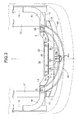
- paired left and right front side frames 11, 11 extending in a front-to-rear direction of a vehicle body are arranged in an automobile on both left and right side portions of a front portion of the vehicle body.
- the front ends of paired left and right upper members 12, 12, which extend downward toward a front of the vehicle body respectively from the front ends of paired left and right front pillars (not shown), are connected to outer surfaces of the front ends of the front side frames 11, 11 through paired left and right stays 13, 13 extending in the lateral direction.
- Paired left and right curved stays 14, 14 extend in directions approaching each other from positions slightly rearward of the front ends of the upper members 12, 12, respectively, and the inner ends of the stays 14, 14 are coupled to the front ends of the front side frames 11, 11 through paired left and right bulkhead side members 15, 15. Both ends of a bumper beam 16 which is disposed to extend in the lateral direction are coupled to the front ends of the front side frames 11, 11 through stays 17, 17.
- Both left and right ends of a bulkhead upper member 18 are respectively coupled to the inner ends of the left and right stays 14, 14 facing to each other and to the upper ends of the left and right bulkhead side members 15, 15.
- a central portion in the lateral direction of the bulkhead upper member 18 and a central portion in the lateral direction of the bumper beam 16 are coupled to each other through a center beam 19 extending in an up-and-down direction.
- both left and right ends of a bulkhead lower member 20 are coupled to the lower ends of the left and right bulk head side members 15, 15, respectively.
- the bulkhead upper member 18 is curved in a U-shape or a V-shape in such a manner as to protrude forward in a plan view.
- the right end of the bulkhead upper member 18 is coupled to the inner end in the lateral direction of the right stay 14 with a pin 21 in such a manner that the bulkhead upper member 18 is pivotable, and a long hole 18a formed in the left end of the bulkhead upper member 18 is coupled to the inner end in the lateral direction of the left stay 14 with a pin 22 in such a manner that the bulkhead upper member 18 is pivotable and slidable.
- the center beam 19, which is fixed at its upper end to the bulkhead upper member 18, has a fragile portion formed of a notch 19a at its lower portion.
- the center beam 19 has a long hole 19b provided at its lower end and coupled to the upper surface of the bumper beam 16 with a pin 23 in such a manner that the center beam 19 is slidable.
- the bumper beam 16 is curved in an arc in such a manner that its central portion protrudes toward the front of the vehicle body, but the central portion of the bulkhead upper member 18, which is curved in a U-shape or a V-shape, protrudes toward the front of the vehicle body more than the central portion of the bumper beam 16.
- the center beam 19 is disposed obliquely in such a manner that its upper end protrudes toward the front of the vehicle body more than its lower end.
- Paired radiator attachment brackets 24, 24 and paired condenser attachment brackets 25, 25 are provided in a protruding manner on the rear edge of the bulkhead upper member 18, and paired rubber radiator support members 26, 26 and paired rubber condenser support members 27, 27 are provided on the upper surface of the bulkhead lower member 20. Further, a radiator 28 is supported between the radiator attachment brackets 24, 24 and the radiator support members 26, 26, and a condenser 29 is supported between the condenser attachment brackets 25, 25 and the condenser support members 27, 27.
- a hood lock 32 configured to lock a striker 31 which is provided on the front edge of a bonnet hood 30 covering an engine room from above, and a stopper 33 configured to elastically support the front edge of the bonnet hood 30 are provided on the upper surface of the bulkhead upper member 18 at the central portion thereof.
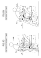
- I indicates the moment of inertia around a gravity center position G of the pedestrian and d ⁇ /dt indicates an angular acceleration around the gravity center position G of the pedestrian
- I d ⁇ / dt F hip L hip + F leg L leg
- L hip indicates a moment arm from the gravity center position G of the pedestrian to the bulkhead upper member 18, and L leg indicates a moment arm from the gravity center position G of the pedestrian to the bumper beam 16.
- the inventions described in Japanese Patent No. 4048461 and Japanese Patent Application Laid-open No. 2007-320530 are designed so that the vehicle body may collide with the leg portion of the pedestrian earlier than the hip portion of the pedestrian. For this reason, the collision load at the leg portion F leg is larger than the collision load at the hip portion F hip .
- the sum of the moments of the right side of the equation (2) is large and the angular velocity of the head is thereby increased.
- the collision load at the hip portion F hip is larger than the collision load at the leg portion F leg when the vehicle collides with the pedestrian. This enables minimizing the angular velocity of the head of the pedestrian and thereby reducing the impact applied when the head collides with the bonnet hood 30.
- the first term of the right side of the equation (1) is the amount of collision energy absorption of the bulkhead upper member 18.
- a collision intermediate phase shown in FIG. 5C the bulkhead upper member 18 is moved further rearward and the bumper beam 16 is moved rearward by the collision with the leg portion of the pedestrian.
- the rearward movement of the bumper beam 16 is completed in this collision intermediate phase. Then, the upper body of the pedestrian whose leg portion has been swept forward by the bumper beam 16 rotates rearward about the gravity center position G.
- the collision energy at the hip portion can be sufficiently absorbed since the distance of the rearward movement of the hip portion X hip is large, and the collision energy can be absorbed also by the rearward movement of the bumper beam 16.
- the collision load at the leg portion F leg is possible to suppress the collision load at the leg portion F leg to be as small as possible, to suppress the moment around the gravity center position G of the pedestrian to a small value, and thereby to prevent the angular velocity of the head from being increased.
- a collision late phase shown in FIG. 5D the rearward movement of the bumper beam 16 is stopped and only the bulkhead upper member 18 is moved rearward to absorb the rest of collision energy.
- the head of the pedestrian may possibly collide with the bonnet hood 30 in this phase; however, since the angular velocity of the head is suppressed to the minimum as described above, the damage to the head can be reduced.
- the bulkhead upper member 18 is located forward of the bumper beam 16 before the collision with the pedestrian, and is moved rearward of the bumper beam 16 by the collision load after the collision with the pedestrian.
- the angular velocity at which the upper body of the pedestrian falls rearward is reduced and thereby the head of the pedestrian is protected.
- the collision energy can be sufficiently absorbed while the collision load to be applied on the hip portion of the pedestrian is prevented from becoming too large.
- the bulkhead upper member 18 is thinner and less stiff than the bumper beam 16, and both ends of the bulkhead upper member 18 are supported by the pins 21, 22 and the long hole 18a in such a manner that the bulkhead upper member 18 is pivotable and slidable.
- the bulkhead upper member 18 can be moved rearward by a load smaller than that for the bumper beam 16. This enables preventing the collision load to be inputted from the bulkhead upper member 18 to the hip portion of the pedestrian from becoming too large while increasing the amount of the rearward movement of the bulkhead upper member 18 to secure the amount of energy absorption.
- the amount of energy absorption of the bulkhead upper member 18 is larger than the amount of energy absorption of the bumper beam 16. This reduces the collision load to be inputted to the leg portion of the pedestrian from the bumper beam 16 whose distance from the gravity center position G of the pedestrian is large, and thereby prevents the upper body of the pedestrian from falling rearward rapidly, thus enabling an effective reduction of the angular velocity of the head.
- the bulkhead upper member 18 and the bumper beam 16 are each supported at its both left and right portions. Thereby, when the pedestrian collides with the central portion in the lateral direction of each of the bulkhead upper member 18 and the bumper beam 16, the bulkhead upper member 18 and the bumper beam 16 are easily deformed to effectively exhibit their energy absorption effect.
- each of the bulkhead upper member 18 and the bumper beam 16 when the pedestrian collides with a position of each of the bulkhead upper member 18 and the bumper beam 16 which is offset in the lateral direction from a central portion thereof in the lateral direction, the bulkhead upper member 18 and the bumper beam 16 are hard to deform and thus the energy absorption effect is low; however, since each of the bulkhead upper member 18 and the bumper beam 16 is curved in a convex shape in such a manner that its central portion in the lateral direction protrudes toward the front of the vehicle body, the collision load can be reduced by letting the pedestrian escape from the collision position toward the outside in the lateral direction.
- both end portions in the lateral direction of the bulkhead upper member 18 are coupled to the stays 14, 14 with the pins 21, 22, respectively, in such a manner that the bulkhead upper member 18 is pivotable.
- one end portion of the bulkhead upper member 18 is coupled to one of the left and right stays 14 with the long hole 18a and the pin 22 in such a manner that the bulkhead upper member 18 is slidable.
- the upper portions of the radiator 28 and the condenser 29 are respectively supported by the radiator attachment brackets 24, 24 and the condenser attachment brackets 25, 25 which are provided to protrude rearward from the bulkhead upper member 18. This makes the upper portions of the radiator 28 and the condenser 29 to lean rearward together with the bulkhead upper member 18 when the bulkhead upper member 18 is deformed rearward by the collision load. Thereby, the damage to the radiator 28 and the condenser 29 can be suppressed to the minimum.
- the hood lock 32 configured to lock the striker 31 provided on the front edge of the bonnet hood 30 is provided at the central portion in the lateral direction of the bulkhead upper member 18, and the central portion in the lateral direction of the bulkhead upper member 18 is coupled to the central portion in the lateral direction of the bumper beam 16 through the center beam 19 extending in the up-and-down direction.
- the center beam 19 includes the notch 19a, at which the center beam 19 is easily bent, at its coupling portion with the bumper beam 16, and is supported by the bumper beam 16 through the long hole 19b and the pin 23 in such a manner that the center beam 19 is slidable back and forth. Accordingly, at the time of a slight collision in which the collision load is inputted only to the bulkhead upper member 18, the center beam 19 is deformed at the notch 19a or the long hole 19b slides relative to the pin 23. Thus, the deformation of the bumper beam 16 can be prevented and the repair cost can be thereby reduced.
- hip portion energy absorption members 18, 18 are obtained by dividing, in the up-and-down direction, the hip portion energy absorption member into two
- leg portion energy absorption members 16, 16 are obtained by dividing, in the up-and-down direction, the leg portion energy absorption member into two.
- hip portion energy absorption members 18 are constituted of multiple energy absorption ribs arranged along the front edge of the bonnet hood 30.
- a hip portion energy absorption member 18 is constituted of a reinforcement member formed of a metal press part or a resin-molded part disposed on the rear surface of a bumper face 34 at an upper portion thereof.
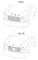
- hip portion energy absorption members 18 are constituted of multiple energy absorption ribs arranged along the rear surface of a front grille 35 at an upper portion thereof.
- a hip portion energy absorption member 18 is constituted of a reinforcement member formed of a metal press part or a resin-molded part disposed on the rear surface of a front grille 35 at an upper portion thereof.
- hip portion energy absorption members 18 forward of the leg portion energy absorption member(s) (bumper beam(s) 16).
- the hip portion energy absorption member of the present invention is not limited to the bulkhead upper member 18 of the embodiments, and the leg portion energy absorption member of the present invention is not limited to the bumper beam 16 of the embodiments.
- the bulkhead upper member 18 and the bumper beam 16 are fixed to the vehicle body.
- one or both of the bulkhead upper member 18 and the bumper beam 16 may be provided to the vehicle body to be movable back and forth. In this case, if it is judged that the vehicle will inevitably collide with the pedestrian, it is only necessary to move the bulkhead upper member 18 and/or the bumper beam 16 forward so that the bulkhead upper member 18 is located forward of the bumper beam 16.
- the right end of the bulkhead upper member 18 is supported by the pin 21 in such a manner that the bulkhead upper member 18 is pivotable, and the left end of the bulkhead upper member 18 is supported by the long hole 18a and the pin 22 in such a manner that the bulkhead upper member 18 is pivotable and slidable.
- the ways of supporting the right end and the left end may be reversed, or both left and right ends may be supported in such a manner that the bulkhead upper member 18 is slidable.
- the long hole 19b allows the center beam 19 to be slidable rearward relative to the bumper beam 16.
- the long hole 19b may allow the bumper beam 16 to be slidable rearward relative to the center beam 19.
- a bulkhead upper member (18) is located forward of a bumper beam (16) before the collision with a pedestrian, and is moved rearward of the bumper beam (16) by a collision load after the collision with the pedestrian.
- the angular velocity at which the upper body of the pedestrian falls rearward is reduced and thereby the head of the pedestrian is protected.
- the collision energy can be sufficiently absorbed while the collision load to be applied on the hip portion of the pedestrian is prevented from becoming too large.
Abstract
Description
- The present invention relates to a pedestrian protection device for a vehicle, the device disposed at a front portion of a vehicle body of a vehicle and configured to absorb collision energy at the time of a collision with a pedestrian.
- Japanese Patent No.
4048461 - Further, Japanese Patent Application Laid-open No.
2007-320530 - Meanwhile, as is the invention described in Japanese Patent No.
4048461 - In addition, as is the invention described in Japanese Patent Application Laid-open No.
2007-320530 - The present invention has been made in view of the foregoing situation. An object of the present invention is to absorb effectively collision energy while suppressing an angular velocity of an upper body of a pedestrian fallen rearward as low as possible, when a front part of a vehicle body collides with the pedestrian.
- In order to achieve the object, according to the invention described in
claim 1, there is provided a pedestrian protection device for a vehicle, the device disposed at a front portion of a vehicle body of a vehicle and configured to absorb collision energy at the time of a collision with a pedestrian, the device characterized by comprising: a hip portion energy absorption member configured to absorb the collision energy by colliding with a hip portion of the pedestrian; and a leg portion energy absorption member configured to absorb the collision energy by colliding with a leg portion of the pedestrian, characterized in that before the collision with the pedestrian, the hip portion energy absorption member is located forward of the leg portion energy absorption member, by the collision with the pedestrian, the hip portion energy absorption member and the leg portion energy absorption member are moved rearward while absorbing the collision energy, and after completion of the collision with the pedestrian, the hip portion energy absorption member is located rearward of the leg portion energy absorption member. - With the above configuration, the hip portion energy absorption member is located forward of the leg portion energy absorption member before the collision with the pedestrian, and is moved rearward of the leg portion energy absorption member by a collision load after completion of the collision with the pedestrian. Hence, by increasing a collision load to be applied on the hip portion energy absorption member which is close to a gravity center position of the pedestrian and reducing a collision load to be applied on the leg portion energy absorption member which is far from the gravity center position of the pedestrian, the angular velocity at which the upper body of the pedestrian falls rearward is reduced and thereby the head of the pedestrian is protected. Moreover, by sufficiently securing the amount of the rearward deformation of the hip portion energy absorption member, the collision energy can be sufficiently absorbed while the collision load to be applied on the hip portion of the pedestrian is prevented from becoming too large.
- Further, according to the invention described in claim 2, in addition to the configuration of
claim 1, there is provided the pedestrian protection device for a vehicle, wherein the hip portion energy absorption member is movable rearward by a load smaller than that for the leg portion energy absorption member. - With the above configuration, the hip portion energy absorption member is movable rearward by the load smaller than that for the leg portion energy absorption member. This enables preventing the collision load to be inputted from the hip portion energy absorption member to the hip portion of the pedestrian from becoming too large while increasing the amount of the rearward movement of the hip portion energy absorption member to secure the amount of energy absorption.
- Further, according to the invention described in
claim 3, in addition to the configuration ofclaim 1 or 2, there is provided the pedestrian protection device for a vehicle, wherein the amount of energy absorption of the hip portion energy absorption member is larger than the amount of energy absorption of the leg portion energy absorption member. - With the above configuration, the amount of energy absorption of the hip portion energy absorption member is larger than the amount of energy absorption of the leg portion energy absorption member. This reduces the collision load to be inputted from the leg portion energy absorption member to the leg portion of the pedestrian, thus enabling an effective reduction of the angular velocity at which the upper body of the pedestrian falls rearward.
- Further, according to the invention described in claim 4, in addition to the configuration of any one of
claims 1 to 3, there is provided the pedestrian protection device for a vehicle, wherein the hip portion energy absorption member is arranged in two stages in an up-and-down direction. - With the above configuration, the hip portion energy absorption member is arranged in two stages in the up-and-down direction. Hence, the flexibility in setting the collision energy absorption characteristics of the hip portion energy absorption member can be improved.
- Further, according to the invention described in claim 5, in addition to the configuration of any one of
claims 1 to 4, there is provided the pedestrian protection device for a vehicle, wherein the leg portion energy absorption member is arranged in two stages in an up-and-down direction. - With the above configuration, the leg portion energy absorption member is arranged in two stages in the up-and-down direction. Hence, the flexibility in setting the collision energy absorption characteristics of the leg portion energy absorption member can be improved.
- Further, according to the invention described in claim 6, in addition to the configuration of any one of
claims 1 to 5, there is provided the pedestrian protection device for a vehicle, wherein the hip portion energy absorption member is an energy absorption rib provided at a front portion of a bonnet hood. - With the above configuration, the hip portion energy absorption member is constituted of the energy absorption rib provided at the front portion of the bonnet hood. Hence, it is easy to dispose the hip portion energy absorption member forward of the leg portion energy absorption member.
- Further, according to the invention described in claim 7, in addition to the configuration of any one of
claims 1 to 5, there is provided the pedestrian protection device for a vehicle, wherein the hip portion energy absorption member is a reinforcement member provided on a back surface of a bumper face. - With the above configuration, the hip portion energy absorption member is constituted of the reinforcement member provided on the back surface of the bumper face. Hence, it is easy to dispose the hip portion energy absorption member forward of the leg portion energy absorption member.
- Further, according to the invention described in claim 8, in addition to the configuration of any one of
claims 1 to 5, there is provided the pedestrian protection device for a vehicle, wherein the hip portion energy absorption member is an energy absorption rib provided on a back surface of a front grille. - With the above configuration, the hip portion energy absorption member is constituted of the energy absorption rib provided on the back surface of the front grille. Hence, it is easy to dispose the hip portion energy absorption member forward of the leg portion energy absorption member.
- Further, according to the invention described in claim 9, in addition to the configuration of any one of
claims 1 to 5, there is provided the pedestrian protection device for a vehicle, wherein the hip portion energy absorption member is a reinforcement member provided on a back surface of a front grille. - With the above configuration, the hip portion energy absorption member is constituted of the reinforcement member provided on the back surface of the front grille. Hence, it is easy to dispose the hip portion energy absorption member forward of the leg portion energy absorption member.
- Further, according to the invention described in claim 10, there is provided a pedestrian protection device for a vehicle, the device disposed at a front portion of a vehicle body of a vehicle and configured to absorb collision energy at the time of a collision with a pedestrian, the device characterized by comprising: a hip portion energy absorption member being curved in a convex shape in such a manner that a central portion thereof in a lateral direction protrudes toward the front of the vehicle body and configured to absorb the collision energy by colliding with a hip portion of the pedestrian; and a leg portion energy absorption member being curved in a convex shape in such a manner that a central portion thereof in a lateral direction protrudes toward the front of the vehicle body and configured to absorb the collision energy by colliding with a leg portion of the pedestrian, characterized in that the central portion in the lateral direction of the hip portion energy absorption member is located forward of the central portion in the lateral direction of the leg portion energy absorption member before the collision with the pedestrian, and is moved rearward of the central portion in the lateral direction of the leg portion energy absorption member by a collision load after the collision with the pedestrian.
- With the above configuration, the central portion in the lateral direction of the hip portion energy absorption member is located forward of the central portion in the lateral direction of the leg portion energy absorption member before the collision with the pedestrian, and is moved rearward of the central portion in the lateral direction of the leg portion energy absorption member by the collision load after the collision with the pedestrian. Hence, by increasing the collision load to be applied on the hip portion energy absorption member which is close to the gravity center position of the pedestrian and reducing the collision load to be applied on the leg portion energy absorption member which is far from the gravity center position of the pedestrian, the angular velocity at which the upper body of the pedestrian falls rearward is reduced and thereby the head of the pedestrian is protected. Moreover, by sufficiently securing the amount of the rearward deformation of the hip portion energy absorption member, the collision energy can be sufficiently absorbed while the collision load to be applied on the hip portion of the pedestrian is prevented from becoming too large. Further, when the pedestrian collides with a position offset in the lateral direction from a central portion of the vehicle body, the hip portion energy absorption member and the leg portion energy absorption member are hard to deform and thus the energy absorption effect is low; however, since each of the hip portion energy absorption member and the leg portion energy absorption member is curved in such a manner that the central portion in the lateral direction thereof protrudes toward the front of the vehicle body in a convex shape, the collision load can be reduced by letting the pedestrian escape from the collision position toward the outside in the lateral direction.
- Further, according to the invention described in
claim 11, in addition to the configuration of claim 10, there is provided the pedestrian protection device for a vehicle, wherein opposite end portions in the lateral direction of the hip portion energy absorption member are coupled to a vehicle body frame in such a manner that the hip portion energy absorption member is pivotable. - With the above configuration, the opposite end portions in the lateral direction of the hip portion energy absorption member are coupled to the vehicle body frame in such a manner that the hip portion energy absorption member is pivotable. Thus, even when the hip portion energy absorption member is deformed rearward by the collision load and the bending load thereby acts on the coupling portion with the vehicle body frame, the deformation of the vehicle body frame due to this bending load can be suppressed to the minimum.
- Further, according to the invention described in
claim 12, in addition to the configuration ofclaim 10 or 11, there is provided the pedestrian protection device for a vehicle, wherein at least one of opposite end portions in the lateral direction of the hip portion energy absorption member is coupled to a vehicle body frame in such a manner that the hip portion energy absorption member is slidable relative to the vehicle body frame. - With the above configuration, at least one of the opposite end portions in the lateral direction of the hip portion energy absorption member is coupled to the vehicle body frame in such a manner that the hip portion energy absorption member is slidable relative to the vehicle body frame. Thus, even when the hip portion energy absorption member is deformed rearward by the collision load and thereby an outward load from the center in the lateral direction of the vehicle body acts on the coupling portion with the vehicle body frame, the deformation of the vehicle body frame due to this load can be suppressed to the minimum.
- Further, according to the invention described in
claim 13, in addition to the configuration of any one of claims 10 to 12, there is provided the pedestrian protection device for a vehicle, wherein an upper portion of a cooling device is supported by an attachment bracket provided to protrude rearward from the hip portion energy absorption member. - With the above configuration, the upper portion of the cooling device is supported by the attachment bracket provided to protrude rearward from the hip portion energy absorption member. This makes the upper portion of the cooling device to lean rearward when the hip portion energy absorption member is deformed rearward by the collision load. Thereby, the damage to the cooling device can be suppressed to the minimum.
- Further, according to the invention described in
claim 14, in addition to the configuration of any one of claims 10 to 13, there is provided the pedestrian protection device for a vehicle, wherein a hood lock configured to fix a front edge of a bonnet hood is provided at the central portion in the lateral direction of the hip portion energy absorption member, and the central portion in the lateral direction of the hip portion energy absorption member is coupled to the central portion in the lateral direction of the leg portion energy absorption member through a coupling member extending in an up-and-down direction. - With the above configuration, the hood lock configured to fix the front edge of the bonnet hood is provided at the central portion in the lateral direction of the hip portion energy absorption member, and the central portion in the lateral direction of the hip portion energy absorption member is coupled to the central portion in the lateral direction of the leg portion energy absorption member through the coupling member extending in the up-and-down direction. Thereby, when the bonnet hood is closed with force, the load generated by this closing operation can be transmitted to the leg portion energy absorption member through the hood lock and the coupling member.
- Further, according to the invention described in
claim 15, in addition to the configuration ofclaim 14, there is provided the pedestrian protection device for a vehicle, wherein the coupling member includes a fragile portion, which is easily bent, at a coupling portion thereof with the leg portion energy absorption member. - With the above configuration, the coupling member includes the fragile portion, which is easily bent, at the coupling portion thereof with the leg portion energy absorption member. Accordingly, at the time of a slight collision in which the collision load is inputted only to the hip portion energy absorption member, the coupling member is deformed at the fragile portion to prevent the deformation of the leg portion energy absorption member. Thereby, the repair cost for the leg portion energy absorption member can be reduced.
- Further, according to the invention described in
claim 16, in addition to the configuration ofclaim - With the above configuration, the coupling member includes the sliding portion, which is slidable back and forth relative to the leg portion energy absorption member, at the coupling portion thereof with the leg portion energy absorption member. Accordingly, at the time of a slight collision in which the collision load is inputted only to the hip portion energy absorption member, the sliding portion of the coupling member slides and thereby the deformation of the leg portion energy absorption member is prevented. Thereby, the repair cost for the leg portion energy absorption member can be reduced. In contrast, at the time of a slight collision in which the collision load is inputted only to the leg portion energy absorption member, the sliding portion of the coupling member slides and thereby only the leg portion energy absorption member is deformed. Thus, the deformation of the hip portion energy absorption member can be prevented and the repair cost for the hip portion energy absorption member can be thereby reduced.
- Here, a
stay 14 of embodiments corresponds to a vehicle body frame of the present invention; abumper beam 16 of the embodiments correspond to the leg portion energy absorption member of the present invention; a bulkheadupper member 18 of the embodiments corresponds to the hip portion energy absorption member of the present invention; acenter beam 19 of the embodiments corresponds to the coupling member of the present invention; anotch 19a of the embodiments corresponds to the fragile portion of the present invention; along hole 19b of the embodiments corresponds to the sliding portion of the present invention; aradiator attachment bracket 24 and acondenser attachment bracket 25 of the embodiments correspond to the attachment bracket of the present invention; and aradiator 28 and acondenser 29 of the embodiments correspond to the cooling device of the present invention. - The above and other objects, characteristics and advantages of the present invention will be clear from detailed descriptions of the preferred embodiments which will be provided below while referring to the attached drawings.
-
-
FIG. 1 to FIG. 5D show a first embodiment of the present invention:FIG. 1 is a perspective view of a front part of a vehicle body of an automobile;FIG. 2 is a sectional view taken along a line 2-2 inFIG. 1 ;FIG. 3 is a view seen from a direction of anarrow 3 inFIG. 1 ;FIG. 4 is a view explaining an operation when the automobile collides with a pedestrian; andFIGS. 5A and5D are views explaining operations when the automobile collides with the pedestrian. -
FIG. 6 is a view showing an alignment of a hip portion energy absorption member and a leg portion energy absorption member according to a second embodiment of the present invention. -
FIG. 7 and 8 are views showing other embodiments of a hip portion energy absorption member according to third and fourth embodiments of the present invention. -
FIG. 9 and 10 are views showing other embodiments of a hip portion energy absorption member according to fifth and sixth embodiments of the present invention. - Descriptions will be hereinbelow provided for a first embodiment of the present invention based on
FIGS. 1 to 5D . - As shown in
FIGS. 1 to 3 , paired left and right front side frames 11, 11 extending in a front-to-rear direction of a vehicle body are arranged in an automobile on both left and right side portions of a front portion of the vehicle body. The front ends of paired left and rightupper members upper members stays bulkhead side members bumper beam 16 which is disposed to extend in the lateral direction are coupled to the front ends of the front side frames 11, 11 throughstays - Both left and right ends of a bulkhead
upper member 18 are respectively coupled to the inner ends of the left and right stays 14, 14 facing to each other and to the upper ends of the left and rightbulkhead side members upper member 18 and a central portion in the lateral direction of thebumper beam 16 are coupled to each other through acenter beam 19 extending in an up-and-down direction. Further, both left and right ends of a bulkheadlower member 20 are coupled to the lower ends of the left and right bulkhead side members - The bulkhead
upper member 18 is curved in a U-shape or a V-shape in such a manner as to protrude forward in a plan view. The right end of the bulkheadupper member 18 is coupled to the inner end in the lateral direction of theright stay 14 with apin 21 in such a manner that the bulkheadupper member 18 is pivotable, and along hole 18a formed in the left end of the bulkheadupper member 18 is coupled to the inner end in the lateral direction of theleft stay 14 with apin 22 in such a manner that the bulkheadupper member 18 is pivotable and slidable. Thecenter beam 19, which is fixed at its upper end to the bulkheadupper member 18, has a fragile portion formed of anotch 19a at its lower portion. Thecenter beam 19 has along hole 19b provided at its lower end and coupled to the upper surface of thebumper beam 16 with apin 23 in such a manner that thecenter beam 19 is slidable. Thebumper beam 16 is curved in an arc in such a manner that its central portion protrudes toward the front of the vehicle body, but the central portion of the bulkheadupper member 18, which is curved in a U-shape or a V-shape, protrudes toward the front of the vehicle body more than the central portion of thebumper beam 16. Hence, thecenter beam 19 is disposed obliquely in such a manner that its upper end protrudes toward the front of the vehicle body more than its lower end. - Paired
radiator attachment brackets condenser attachment brackets upper member 18, and paired rubberradiator support members condenser support members lower member 20. Further, aradiator 28 is supported between theradiator attachment brackets radiator support members condenser 29 is supported between thecondenser attachment brackets condenser support members - A
hood lock 32 configured to lock astriker 31 which is provided on the front edge of abonnet hood 30 covering an engine room from above, and astopper 33 configured to elastically support the front edge of thebonnet hood 30 are provided on the upper surface of the bulkheadupper member 18 at the central portion thereof. - Next, description will be given of an operation of the embodiment of the present invention having the above configuration.
- Referring to
FIG. 4 , consider a case where a vehicle collides with a pedestrian at a vehicle velocity Vveh. Assume that, by the collision with the pedestrian, the bulkheadupper member 18 being a hip portion energy absorption member is moved rearward by a distance Xhip with a collision load Fhip, and thebumper beam 16 being a leg portion energy absorption member is moved rearward by a distance Xleg with a collision load Fleg. In this event, assuming that the kinetic energy of the pedestrian, which has been accelerated to the vehicle velocity Vveh by the collision is absorbed by the rearward movement of each of the bulkheadupper member 18 and thebumper beam 16, the following law of the conservation of energy is satisfied:
Here, M is the mass of the pedestrian. - Further, when I indicates the moment of inertia around a gravity center position G of the pedestrian and dω/dt indicates an angular acceleration around the gravity center position G of the pedestrian, the following angular motion equation is satisfied:

Here, Lhip indicates a moment arm from the gravity center position G of the pedestrian to the bulkheadupper member 18, and Lleg indicates a moment arm from the gravity center position G of the pedestrian to thebumper beam 16. - In order to reduce an angular velocity at which the head of the pedestrian collides with the
bonnet hood 30 in the equation (2), the angular acceleration dω/dt on the left side needs to be reduced. To this end, it is necessary to reduce the moment Fhip Lhip by the collision load at the hip portion Fhip shown as the first term of the right side and the moment Fleg Lleg by the collision load at the leg portion Fleg shown as the second term of the right side. - In this event, it is ideal to reduce both of the collision load at the hip portion Fhip and the collision load at the leg portion Fleg. However, what can be done realistically is only to increase one of the collision load at the hip portion Fhip and the collision load at the leg portion Fleg and reduce the other since the sum of the collision load at the hip portion Fhip and the collision load at the leg portion Fleg is almost constant.
- To cope with this, when attention is focused on the moment arm Lhip from the gravity center position G to the bulkhead
upper member 18 and the moment arm Lleg from the gravity center position G to thebumper beam 16, Lhip < Lleg is satisfied. Thus, by reducing the collision load at the leg portion Fleg by which the larger moment arm Lleg is multiplied and increasing the collision load at the hip portion Fhip by which the smaller moment arm Lhip is multiplied, it is possible to minimize the sum of the moments on the right side of the equation (2), to minimize the angular acceleration dω/dt around the gravity center position of the pedestrian on the left side, and thereby to reduce the angular velocity of the head. - In this regard, the inventions described in Japanese Patent No.
4048461 2007-320530 - On the other hand, according to this embodiment, since the bulkhead
upper member 18 protrudes forward of thebumper beam 16, the collision load at the hip portion Fhip is larger than the collision load at the leg portion Fleg when the vehicle collides with the pedestrian. This enables minimizing the angular velocity of the head of the pedestrian and thereby reducing the impact applied when the head collides with thebonnet hood 30. - As described above, in order to minimize the angular velocity of the head of the pedestrian, it is effective to increase the collision load at the hip portion Fhip and reduce the collision load at the leg portion Fleg. However, since too large collision load at the hip portion Fhip may possibly damage the hip portion of the pedestrian, it is difficult to increase the collision load at the hip portion Fhip beyond a limit value. The first term of the right side of the equation (1) is the amount of collision energy absorption of the bulkhead
upper member 18. Even when the collision load at the hip portion Fhip in the first term cannot be increased, an increase in the distance of the rearward movement of the hip portion Xhip by the deformation of the bulkheadupper member 18 leads to an increase, to the maximum, of the amount of energy absorption of the bulkheadupper member 18 and to a reduction of the amount of energy absorption to be imposed on thebumper beam 16. Thereby, the angular velocity of the head of the pedestrian can be reduced. - To be more specific, as shown in
FIG. 5A , when the front portion of the vehicle collides with the pedestrian, the bulkheadupper member 18 protruding toward the front of the vehicle body comes into contact with the hip portion of the pedestrian first, and a velocity Vp at the gravity center position G of the pedestrian is thereby increased gradually. In a collision early phase shown inFIG. 5B , the bulkheadupper member 18 is moved rearward by the collision with the hip portion of the pedestrian to absorb collision energy, and thebumper beam 16 comes into contact with the leg portion of the pedestrian later than the bulkheadupper member 18. - In a collision intermediate phase shown in
FIG. 5C , the bulkheadupper member 18 is moved further rearward and thebumper beam 16 is moved rearward by the collision with the leg portion of the pedestrian. However, since a stroke by which thebumper beam 16 can be moved rearward is set small, the rearward movement of thebumper beam 16 is completed in this collision intermediate phase. Then, the upper body of the pedestrian whose leg portion has been swept forward by thebumper beam 16 rotates rearward about the gravity center position G. In this event, even when the stiffness of the bulkheadupper member 18 is set low so that the collision load at the hip portion Fhip may not exceed the limit value, the collision energy at the hip portion can be sufficiently absorbed since the distance of the rearward movement of the hip portion Xhip is large, and the collision energy can be absorbed also by the rearward movement of thebumper beam 16. Thus, by securing the largest possible collision load at the hip portion Fhip within the range of the limit value, it is possible to suppress the collision load at the leg portion Fleg to be as small as possible, to suppress the moment around the gravity center position G of the pedestrian to a small value, and thereby to prevent the angular velocity of the head from being increased. - In a collision late phase shown in
FIG. 5D , the rearward movement of thebumper beam 16 is stopped and only the bulkheadupper member 18 is moved rearward to absorb the rest of collision energy. The head of the pedestrian may possibly collide with thebonnet hood 30 in this phase; however, since the angular velocity of the head is suppressed to the minimum as described above, the damage to the head can be reduced. - As has been described, according to this embodiment, the bulkhead
upper member 18 is located forward of thebumper beam 16 before the collision with the pedestrian, and is moved rearward of thebumper beam 16 by the collision load after the collision with the pedestrian. Hence, by increasing the collision load to be applied on the bulkheadupper member 18 which is close to the gravity center position G of the pedestrian and reducing the collision load to be applied on thebumper beam 16 which is far from the gravity center position G of the pedestrian, the angular velocity at which the upper body of the pedestrian falls rearward is reduced and thereby the head of the pedestrian is protected. Moreover, by sufficiently securing the amount of the rearward deformation of the bulkheadupper member 18, the collision energy can be sufficiently absorbed while the collision load to be applied on the hip portion of the pedestrian is prevented from becoming too large. - Further, the bulkhead
upper member 18 is thinner and less stiff than thebumper beam 16, and both ends of the bulkheadupper member 18 are supported by thepins long hole 18a in such a manner that the bulkheadupper member 18 is pivotable and slidable. Thus, the bulkheadupper member 18 can be moved rearward by a load smaller than that for thebumper beam 16. This enables preventing the collision load to be inputted from the bulkheadupper member 18 to the hip portion of the pedestrian from becoming too large while increasing the amount of the rearward movement of the bulkheadupper member 18 to secure the amount of energy absorption. - Further, the amount of energy absorption of the bulkhead
upper member 18 is larger than the amount of energy absorption of thebumper beam 16. This reduces the collision load to be inputted to the leg portion of the pedestrian from thebumper beam 16 whose distance from the gravity center position G of the pedestrian is large, and thereby prevents the upper body of the pedestrian from falling rearward rapidly, thus enabling an effective reduction of the angular velocity of the head. - Further, the bulkhead
upper member 18 and thebumper beam 16 are each supported at its both left and right portions. Thereby, when the pedestrian collides with the central portion in the lateral direction of each of the bulkheadupper member 18 and thebumper beam 16, the bulkheadupper member 18 and thebumper beam 16 are easily deformed to effectively exhibit their energy absorption effect. On the other hand, when the pedestrian collides with a position of each of the bulkheadupper member 18 and thebumper beam 16 which is offset in the lateral direction from a central portion thereof in the lateral direction, the bulkheadupper member 18 and thebumper beam 16 are hard to deform and thus the energy absorption effect is low; however, since each of the bulkheadupper member 18 and thebumper beam 16 is curved in a convex shape in such a manner that its central portion in the lateral direction protrudes toward the front of the vehicle body, the collision load can be reduced by letting the pedestrian escape from the collision position toward the outside in the lateral direction. - Further, both end portions in the lateral direction of the bulkhead
upper member 18 are coupled to thestays pins upper member 18 is pivotable. Thus, even when the bulkheadupper member 18 is deformed rearward by the collision load and a bending load thereby acts on the coupling portions with thestays stays - Further, one end portion of the bulkhead
upper member 18 is coupled to one of the left and right stays 14 with thelong hole 18a and thepin 22 in such a manner that the bulkheadupper member 18 is slidable. Thus, even when the bulkheadupper member 18 is deformed rearward by the collision load and an outward load from the center in the lateral direction of the vehicle body thereby acts on the coupling portions with the left and right stays 14, 14, the deformation of thestays - Further, the upper portions of the
radiator 28 and thecondenser 29 are respectively supported by theradiator attachment brackets condenser attachment brackets upper member 18. This makes the upper portions of theradiator 28 and thecondenser 29 to lean rearward together with the bulkheadupper member 18 when the bulkheadupper member 18 is deformed rearward by the collision load. Thereby, the damage to theradiator 28 and thecondenser 29 can be suppressed to the minimum. - Further, the
hood lock 32 configured to lock thestriker 31 provided on the front edge of thebonnet hood 30 is provided at the central portion in the lateral direction of the bulkheadupper member 18, and the central portion in the lateral direction of the bulkheadupper member 18 is coupled to the central portion in the lateral direction of thebumper beam 16 through thecenter beam 19 extending in the up-and-down direction. Thereby, when thebonnet hood 30 is closed with force, the load generated by this closing operation can be transmitted to thebumper beam 16 through thehood lock 32 and the center beam 19 (seeFIG. 2 ). - Further, the
center beam 19 includes thenotch 19a, at which thecenter beam 19 is easily bent, at its coupling portion with thebumper beam 16, and is supported by thebumper beam 16 through thelong hole 19b and thepin 23 in such a manner that thecenter beam 19 is slidable back and forth. Accordingly, at the time of a slight collision in which the collision load is inputted only to the bulkheadupper member 18, thecenter beam 19 is deformed at thenotch 19a or thelong hole 19b slides relative to thepin 23. Thus, the deformation of thebumper beam 16 can be prevented and the repair cost can be thereby reduced. - Next, a second embodiment of the present invention will be described on the basis of
FIG. 6 . - In the second embodiment, hip portion
energy absorption members energy absorption members energy absorption members energy absorption members - Next, other embodiments of the present invention will be described on the basis of
FIGS. 7 to 10 . - In a third embodiment of the present invention shown in
FIG. 7 , hip portionenergy absorption members 18 are constituted of multiple energy absorption ribs arranged along the front edge of thebonnet hood 30. - In a fourth embodiment of the present invention shown in
FIG. 8 , a hip portionenergy absorption member 18 is constituted of a reinforcement member formed of a metal press part or a resin-molded part disposed on the rear surface of abumper face 34 at an upper portion thereof. - In a fifth embodiment of the present invention shown in
FIG. 9 , hip portionenergy absorption members 18 are constituted of multiple energy absorption ribs arranged along the rear surface of afront grille 35 at an upper portion thereof. - In a sixth embodiment of the present invention shown in
FIG. 10 , a hip portionenergy absorption member 18 is constituted of a reinforcement member formed of a metal press part or a resin-molded part disposed on the rear surface of afront grille 35 at an upper portion thereof. - According to these second and third embodiments, it is easy to arrange the hip portion
energy absorption members 18 forward of the leg portion energy absorption member(s) (bumper beam(s) 16). - Although the embodiments of the present invention have been described thus far, various design changes can be made within a range not deviating from the gist of the present invention.
- For example, the hip portion energy absorption member of the present invention is not limited to the bulkhead
upper member 18 of the embodiments, and the leg portion energy absorption member of the present invention is not limited to thebumper beam 16 of the embodiments. - Further, according to the embodiments, the bulkhead
upper member 18 and thebumper beam 16 are fixed to the vehicle body. However, one or both of the bulkheadupper member 18 and thebumper beam 16 may be provided to the vehicle body to be movable back and forth. In this case, if it is judged that the vehicle will inevitably collide with the pedestrian, it is only necessary to move the bulkheadupper member 18 and/or thebumper beam 16 forward so that the bulkheadupper member 18 is located forward of thebumper beam 16. - Further, according to the embodiments, the right end of the bulkhead
upper member 18 is supported by thepin 21 in such a manner that the bulkheadupper member 18 is pivotable, and the left end of the bulkheadupper member 18 is supported by thelong hole 18a and thepin 22 in such a manner that the bulkheadupper member 18 is pivotable and slidable. However, the ways of supporting the right end and the left end may be reversed, or both left and right ends may be supported in such a manner that the bulkheadupper member 18 is slidable. - Further, according to the embodiments, the
long hole 19b allows thecenter beam 19 to be slidable rearward relative to thebumper beam 16. However, thelong hole 19b may allow thebumper beam 16 to be slidable rearward relative to thecenter beam 19. With this configuration, at the time of a slight collision in which the collision load is inputted only to thebumper beam 16, thelong hole 19b of thecenter beam 19 slides and thereby only thebumper beam 16 is deformed. Thus, the deformation of the bulkheadupper member 18 can be prevented and the repair cost for the bulkheadupper member 18 can be thereby reduced. - A bulkhead upper member (18) is located forward of a bumper beam (16) before the collision with a pedestrian, and is moved rearward of the bumper beam (16) by a collision load after the collision with the pedestrian. Hence, by increasing a collision load to be applied on the bulkhead upper member (18) which is close to a gravity center position of the pedestrian and reducing a collision load to be applied on the bumper beam (16) which is far from the gravity center position of the pedestrian, the angular velocity at which the upper body of the pedestrian falls rearward is reduced and thereby the head of the pedestrian is protected. Moreover, by sufficiently securing the amount of the rearward deformation of the bulkhead upper member (18), the collision energy can be sufficiently absorbed while the collision load to be applied on the hip portion of the pedestrian is prevented from becoming too large.
Claims (16)
- A pedestrian protection device for a vehicle, the device disposed at a front portion of a vehicle body of a vehicle and configured to absorb collision energy at the time of a collision with a pedestrian, the device characterized by comprising:a hip portion energy absorption member (18) configured to absorb the collision energy by colliding with a hip portion of the pedestrian; anda leg portion energy absorption member (16) configured to absorb the collision energy by colliding with a leg portion of the pedestrian, characterized in thatbefore the collision with the pedestrian, the hip portion energy absorption member (18) is located forward of the leg portion energy absorption member (16),by the collision with the pedestrian, the hip portion energy absorption member (18) and the leg portion energy absorption member (16) are moved rearward while absorbing the collision energy, andafter completion of the collision with the pedestrian, the hip portion energy absorption member (18) is located rearward of the leg portion energy absorption member (16).
- The pedestrian protection device for a vehicle according to claim 1, wherein the hip portion energy absorption member (18) is movable rearward by a load smaller than that for the leg portion energy absorption member (16).
- The pedestrian protection device for a vehicle according to claim 1 or 2, wherein the amount of energy absorption of the hip portion energy absorption member (18) is larger than the amount of energy absorption of the leg portion energy absorption member (16).
- The pedestrian protection device for a vehicle according to any one of claims 1 to 3, wherein the hip portion energy absorption member (18) is arranged in two stages in an up-and-down direction.
- The pedestrian protection device for a vehicle according to any one of claims 1 to 4, wherein the leg portion energy absorption member (16) is arranged in two stages in an up-and-down direction.
- The pedestrian protection device for a vehicle according to any one of claims 1 to 5, wherein the hip portion energy absorption member (18) is an energy absorption rib provided at a front portion of a bonnet hood (30).
- The pedestrian protection device for a vehicle according to any one of claims 1 to 5, wherein the hip portion energy absorption member (18) is a reinforcement member provided on a back surface of a bumper face (34).
- The pedestrian protection device for a vehicle according to any one of claims 1 to 5, wherein the hip portion energy absorption member (18) is an energy absorption rib provided on a back surface of a front grille (35).
- The pedestrian protection device for a vehicle according to any one of claims 1 to 5, wherein the hip portion energy absorption member (18) is a reinforcement member provided on a back surface of a front grille (35).
- A pedestrian protection device for a vehicle, the device disposed at a front portion of a vehicle body of a vehicle and configured to absorb collision energy at the time of a collision with a pedestrian, the device characterized by comprising:a hip portion energy absorption member (18) being curved in a convex shape in such a manner that a central portion thereof in a lateral direction protrudes toward the front of the vehicle body and configured to absorb the collision energy by colliding with a hip portion of the pedestrian; anda leg portion energy absorption member (16) being curved in a convex shape in such a manner that a central portion thereof in a lateral direction protrudes toward the front of the vehicle body and configured to absorb the collision energy by colliding with a leg portion of the pedestrian, characterized in thatthe central portion in the lateral direction of the hip portion energy absorption member (18) is located forward of the central portion in the lateral direction of the leg portion energy absorption member (16) before the collision with the pedestrian, and is moved rearward of the central portion in the lateral direction of the leg portion energy absorption member (16) by a collision load after the collision with the pedestrian.
- The pedestrian protection device for a vehicle according to claim 10, wherein opposite end portions in the lateral direction of the hip portion energy absorption member (18) are coupled to a vehicle body frame (14) in such a manner that the hip portion energy absorption member (18) is pivotable.
- The pedestrian protection device for a vehicle according to claim 10 or 11, wherein at least one of opposite end portions in the lateral direction of the hip portion energy absorption member (18) is coupled to a vehicle body frame (14) in such a manner that the hip portion energy absorption member (18) is slidable relative to the vehicle body frame (14).
- The pedestrian protection device for a vehicle according to any one of claims 10 to 12, wherein an upper portion of a cooling device (28, 29) is supported by an attachment bracket (24, 25) provided to protrude rearward from the hip portion energy absorption member (18).
- The pedestrian protection device for a vehicle according to any one of claims 10 to 13, wherein
a hood lock (32) configured to fix a front edge of a bonnet hood (30) is provided at the central portion in the lateral direction of the hip portion energy absorption member (18), and
the central portion in the lateral direction of the hip portion energy absorption member (18) is coupled to the central portion in the lateral direction of the leg portion energy absorption member (16) through a coupling member (19) extending in an up-and-down direction. - The pedestrian protection device for a vehicle according to claim 14, wherein the coupling member (19) includes a fragile portion (19a), which is easily bent, at a coupling portion thereof with the leg portion energy absorption member (16).
- The pedestrian protection device for a vehicle according to claim 14 or 15, wherein the coupling member (19) includes a sliding portion (19b), which is slidable back and forth relative to the leg portion energy absorption member (16), at the coupling portion thereof with the leg portion energy absorption member (16).
Applications Claiming Priority (2)
| Application Number | Priority Date | Filing Date | Title |
|---|---|---|---|
| JP2010088640A JP5426457B2 (en) | 2010-04-07 | 2010-04-07 | Pedestrian protection device for vehicles |
| JP2010088639A JP5484163B2 (en) | 2010-04-07 | 2010-04-07 | Pedestrian protection device for vehicles |
Publications (2)
| Publication Number | Publication Date |
|---|---|
| EP2374665A1 true EP2374665A1 (en) | 2011-10-12 |
| EP2374665B1 EP2374665B1 (en) | 2012-08-29 |
Family
ID=43970991
Family Applications (1)
| Application Number | Title | Priority Date | Filing Date |
|---|---|---|---|
| EP20110156024 Not-in-force EP2374665B1 (en) | 2010-04-07 | 2011-02-25 | Pedestrian protection device for vehicle |
Country Status (1)
| Country | Link |
|---|---|
| EP (1) | EP2374665B1 (en) |
Cited By (8)
| Publication number | Priority date | Publication date | Assignee | Title |
|---|---|---|---|---|
| EP2682312A1 (en) * | 2012-07-03 | 2014-01-08 | Volvo Car Corporation | Bonnet latch bracket arrangement |
| FR2995573A1 (en) * | 2012-09-14 | 2014-03-21 | Peugeot Citroen Automobiles Sa | Bumper support frame for front face of car, has base including reinforcement element extending along base from frame until end of base is arranged, where element limits deformation of base during repairability shock on front face of vehicle |
| DE102014224438A1 (en) * | 2014-11-28 | 2016-06-02 | Bayerische Motoren Werke Aktiengesellschaft | Front end assembly for a motor vehicle |
| CN105946753A (en) * | 2016-05-07 | 2016-09-21 | 安徽安凯汽车股份有限公司 | Frontal collision protection structure for low-drive-zone passenger car |
| US20160325709A1 (en) * | 2015-05-08 | 2016-11-10 | GM Global Technology Operations LLC | Support structure for supporting external panel components of a vehicle |
| US9834086B2 (en) | 2015-02-18 | 2017-12-05 | Toyota Jidosha Kabushiki Kaisha | Radiator support structure |
| DE102014217420B4 (en) | 2013-10-15 | 2018-07-26 | Suzuki Motor Corp. | Body front structure |
| FR3122155A1 (en) * | 2021-04-22 | 2022-10-28 | Psa Automobiles Sa | FRAME FOR RETAINING A BUMPER OF A MOTOR VEHICLE COMPRISING A FOLDING ZONE |
Families Citing this family (2)
| Publication number | Priority date | Publication date | Assignee | Title |
|---|---|---|---|---|
| CN103754189B (en) * | 2014-01-23 | 2016-03-16 | 奇瑞汽车股份有限公司 | The automobile upper leg protection of pedestrian and automobile |
| DE102016008210A1 (en) * | 2016-07-06 | 2017-08-31 | Daimler Ag | Deformation device for a stem of a motor vehicle |
Citations (9)
| Publication number | Priority date | Publication date | Assignee | Title |
|---|---|---|---|---|
| JPH0448461B2 (en) | 1985-05-24 | 1992-08-06 | Toyo Seikan Kaisha Ltd | |
| GB2321624A (en) * | 1997-01-27 | 1998-08-05 | Lin Pac Mouldings | Bumper assembly with forwardly displaceable lower portion |
| DE10149443A1 (en) * | 2000-10-13 | 2002-05-02 | Ford Global Tech Inc | Multifunctional support assembly for motor vehicle's radiator has radiator mounting for functional connection to front end section of vehicle and consisting of material based on magnesium or magnesium alloy |
| EP1619089A1 (en) * | 2004-07-05 | 2006-01-25 | Faurecia Bloc Avant | Front module for motor vehicle |
| JP2007320530A (en) | 2006-06-05 | 2007-12-13 | Toyota Motor Corp | Pedestrian collision mitigating device |
| FR2911557A1 (en) * | 2007-01-23 | 2008-07-25 | Plastic Omnium Cie | Frontal impact e.g. insurance type impact, absorption module for motor vehicle, has lower transversal beam and abutment connecting upper transversal element and beam to form frame e.g. absorber frame, and central reinforcement |
| FR2919566A1 (en) * | 2007-08-03 | 2009-02-06 | Faurecia Bloc Avant | FRONT PANEL OF MOTOR VEHICLE WITH TRAVERSE AT THE LEVEL OF THE MAIN LONGERONS |
| FR2923782A1 (en) * | 2007-11-19 | 2009-05-22 | Peugeot Citroen Automobiles Sa | Front block structure for motor vehicle, has femur shock energy absorption system with ends associated to fixation tabs on upper crossbar and upper bumper beam, and deforming by buckling for absorbing energy of femur shock of pedestrian |
| FR2932747A1 (en) * | 2008-06-18 | 2009-12-25 | Faurecia Bloc Avant | Front facebar structure for car, has central absorption element including outer surface that is projected towards outside with respect to body elements such that outer surface is visible from outside of vehicle |
-
2011
- 2011-02-25 EP EP20110156024 patent/EP2374665B1/en not_active Not-in-force
Patent Citations (9)
| Publication number | Priority date | Publication date | Assignee | Title |
|---|---|---|---|---|
| JPH0448461B2 (en) | 1985-05-24 | 1992-08-06 | Toyo Seikan Kaisha Ltd | |
| GB2321624A (en) * | 1997-01-27 | 1998-08-05 | Lin Pac Mouldings | Bumper assembly with forwardly displaceable lower portion |
| DE10149443A1 (en) * | 2000-10-13 | 2002-05-02 | Ford Global Tech Inc | Multifunctional support assembly for motor vehicle's radiator has radiator mounting for functional connection to front end section of vehicle and consisting of material based on magnesium or magnesium alloy |
| EP1619089A1 (en) * | 2004-07-05 | 2006-01-25 | Faurecia Bloc Avant | Front module for motor vehicle |
| JP2007320530A (en) | 2006-06-05 | 2007-12-13 | Toyota Motor Corp | Pedestrian collision mitigating device |
| FR2911557A1 (en) * | 2007-01-23 | 2008-07-25 | Plastic Omnium Cie | Frontal impact e.g. insurance type impact, absorption module for motor vehicle, has lower transversal beam and abutment connecting upper transversal element and beam to form frame e.g. absorber frame, and central reinforcement |
| FR2919566A1 (en) * | 2007-08-03 | 2009-02-06 | Faurecia Bloc Avant | FRONT PANEL OF MOTOR VEHICLE WITH TRAVERSE AT THE LEVEL OF THE MAIN LONGERONS |
| FR2923782A1 (en) * | 2007-11-19 | 2009-05-22 | Peugeot Citroen Automobiles Sa | Front block structure for motor vehicle, has femur shock energy absorption system with ends associated to fixation tabs on upper crossbar and upper bumper beam, and deforming by buckling for absorbing energy of femur shock of pedestrian |
| FR2932747A1 (en) * | 2008-06-18 | 2009-12-25 | Faurecia Bloc Avant | Front facebar structure for car, has central absorption element including outer surface that is projected towards outside with respect to body elements such that outer surface is visible from outside of vehicle |
Cited By (16)
| Publication number | Priority date | Publication date | Assignee | Title |
|---|---|---|---|---|
| EP2682312A1 (en) * | 2012-07-03 | 2014-01-08 | Volvo Car Corporation | Bonnet latch bracket arrangement |
| CN103523097A (en) * | 2012-07-03 | 2014-01-22 | 沃尔沃汽车公司 | Bonnet latch bracket arrangement |
| CN103523097B (en) * | 2012-07-03 | 2018-03-30 | 沃尔沃汽车公司 | Bonnet latch bracket arrangement |
| US9689181B2 (en) | 2012-07-03 | 2017-06-27 | Volvo Car Corporation | Bonnet latch bracket arrangement |
| FR2995573A1 (en) * | 2012-09-14 | 2014-03-21 | Peugeot Citroen Automobiles Sa | Bumper support frame for front face of car, has base including reinforcement element extending along base from frame until end of base is arranged, where element limits deformation of base during repairability shock on front face of vehicle |
| DE102014217420B4 (en) | 2013-10-15 | 2018-07-26 | Suzuki Motor Corp. | Body front structure |
| DE102014224438A1 (en) * | 2014-11-28 | 2016-06-02 | Bayerische Motoren Werke Aktiengesellschaft | Front end assembly for a motor vehicle |
| US10328975B2 (en) | 2014-11-28 | 2019-06-25 | Bayerische Motoren Werke Aktiengesellschaft | Front end assembly for a motor vehicle |
| US9834086B2 (en) | 2015-02-18 | 2017-12-05 | Toyota Jidosha Kabushiki Kaisha | Radiator support structure |
| US9873404B2 (en) * | 2015-05-08 | 2018-01-23 | GM Global Technology Operations LLC | Support structure for supporting external panel components of a vehicle |
| CN106114642A (en) * | 2015-05-08 | 2016-11-16 | 通用汽车环球科技运作有限责任公司 | For supporting the supporting structure of the external decorating member of vehicle |
| US20160325709A1 (en) * | 2015-05-08 | 2016-11-10 | GM Global Technology Operations LLC | Support structure for supporting external panel components of a vehicle |
| CN106114642B (en) * | 2015-05-08 | 2020-04-10 | 通用汽车环球科技运作有限责任公司 | Support structure for supporting an external trim component of a vehicle |
| CN105946753B (en) * | 2016-05-07 | 2018-06-22 | 安徽安凯汽车股份有限公司 | Crash protection structure before a kind of low driver's compartment car |
| CN105946753A (en) * | 2016-05-07 | 2016-09-21 | 安徽安凯汽车股份有限公司 | Frontal collision protection structure for low-drive-zone passenger car |
| FR3122155A1 (en) * | 2021-04-22 | 2022-10-28 | Psa Automobiles Sa | FRAME FOR RETAINING A BUMPER OF A MOTOR VEHICLE COMPRISING A FOLDING ZONE |
Also Published As
| Publication number | Publication date |
|---|---|
| EP2374665B1 (en) | 2012-08-29 |
Similar Documents
| Publication | Publication Date | Title |
|---|---|---|
| EP2374665B1 (en) | Pedestrian protection device for vehicle | |
| JP6131837B2 (en) | Vehicle front structure | |
| US10596994B2 (en) | Front structure of vehicle | |
| JP5433652B2 (en) | Vehicle front structure | |
| JP6807241B2 (en) | Vehicle front structure | |
| JP6224466B2 (en) | Shock absorption bracket | |
| JP2013220783A (en) | Front structure of vehicle | |
| JP6863036B2 (en) | Vehicle front structure | |
| JP5484163B2 (en) | Pedestrian protection device for vehicles | |
| JP6131838B2 (en) | Vehicle front structure | |
| JP4798485B2 (en) | Vehicle front bumper structure | |
| JP4042129B2 (en) | Hood structure | |
| JP5426457B2 (en) | Pedestrian protection device for vehicles | |
| JP2011121437A (en) | Vehicle body front part structure of vehicle | |
| JP4449523B2 (en) | Resin vehicle parts | |
| JP5317861B2 (en) | Hood panel and vehicle front structure with excellent pedestrian protection | |
| JP6139201B2 (en) | Body front structure | |
| JP4905678B2 (en) | Body structure at the front of the vehicle | |
| JP4103711B2 (en) | Radiator support structure | |
| JP6001481B2 (en) | Body front structure | |
| KR101124981B1 (en) | Hood striker for vehicle | |
| JP4349243B2 (en) | Vehicle front structure | |
| JP6844489B2 (en) | Vehicle front structure | |
| JP6733589B2 (en) | Vehicle front bumper | |
| JP7102056B2 (en) | Pedestrian protection device for vehicles |
Legal Events
| Date | Code | Title | Description |
|---|---|---|---|
| PUAI | Public reference made under article 153(3) epc to a published international application that has entered the european phase |
Free format text: ORIGINAL CODE: 0009012 |
|
| 17P | Request for examination filed |
Effective date: 20110225 |
|
| AK | Designated contracting states |
Kind code of ref document: A1 Designated state(s): AL AT BE BG CH CY CZ DE DK EE ES FI FR GB GR HR HU IE IS IT LI LT LU LV MC MK MT NL NO PL PT RO RS SE SI SK SM TR |
|
| AX | Request for extension of the european patent |
Extension state: BA ME |
|
| GRAP | Despatch of communication of intention to grant a patent |
Free format text: ORIGINAL CODE: EPIDOSNIGR1 |
|
| GRAS | Grant fee paid |
Free format text: ORIGINAL CODE: EPIDOSNIGR3 |
|
| GRAA | (expected) grant |
Free format text: ORIGINAL CODE: 0009210 |
|
| AK | Designated contracting states |
Kind code of ref document: B1 Designated state(s): AL AT BE BG CH CY CZ DE DK EE ES FI FR GB GR HR HU IE IS IT LI LT LU LV MC MK MT NL NO PL PT RO RS SE SI SK SM TR |
|
| REG | Reference to a national code |
Ref country code: GB Ref legal event code: FG4D |
|
| REG | Reference to a national code |
Ref country code: CH Ref legal event code: EP |
|
| REG | Reference to a national code |
Ref country code: AT Ref legal event code: REF Ref document number: 572883 Country of ref document: AT Kind code of ref document: T Effective date: 20120915 |
|
| REG | Reference to a national code |
Ref country code: IE Ref legal event code: FG4D |
|
| REG | Reference to a national code |
Ref country code: DE Ref legal event code: R096 Ref document number: 602011000175 Country of ref document: DE Effective date: 20121018 |
|
| REG | Reference to a national code |
Ref country code: AT Ref legal event code: MK05 Ref document number: 572883 Country of ref document: AT Kind code of ref document: T Effective date: 20120829 |
|
| REG | Reference to a national code |
Ref country code: NL Ref legal event code: VDEP Effective date: 20120829 |
|
| REG | Reference to a national code |
Ref country code: LT Ref legal event code: MG4D Effective date: 20120829 |
|
| PG25 | Lapsed in a contracting state [announced via postgrant information from national office to epo] |
Ref country code: LT Free format text: LAPSE BECAUSE OF FAILURE TO SUBMIT A TRANSLATION OF THE DESCRIPTION OR TO PAY THE FEE WITHIN THE PRESCRIBED TIME-LIMIT Effective date: 20120829 Ref country code: IS Free format text: LAPSE BECAUSE OF FAILURE TO SUBMIT A TRANSLATION OF THE DESCRIPTION OR TO PAY THE FEE WITHIN THE PRESCRIBED TIME-LIMIT Effective date: 20121229 Ref country code: HR Free format text: LAPSE BECAUSE OF FAILURE TO SUBMIT A TRANSLATION OF THE DESCRIPTION OR TO PAY THE FEE WITHIN THE PRESCRIBED TIME-LIMIT Effective date: 20120829 Ref country code: FI Free format text: LAPSE BECAUSE OF FAILURE TO SUBMIT A TRANSLATION OF THE DESCRIPTION OR TO PAY THE FEE WITHIN THE PRESCRIBED TIME-LIMIT Effective date: 20120829 Ref country code: AT Free format text: LAPSE BECAUSE OF FAILURE TO SUBMIT A TRANSLATION OF THE DESCRIPTION OR TO PAY THE FEE WITHIN THE PRESCRIBED TIME-LIMIT Effective date: 20120829 Ref country code: NO Free format text: LAPSE BECAUSE OF FAILURE TO SUBMIT A TRANSLATION OF THE DESCRIPTION OR TO PAY THE FEE WITHIN THE PRESCRIBED TIME-LIMIT Effective date: 20121129 |
|
| PG25 | Lapsed in a contracting state [announced via postgrant information from national office to epo] |
Ref country code: BE Free format text: LAPSE BECAUSE OF FAILURE TO SUBMIT A TRANSLATION OF THE DESCRIPTION OR TO PAY THE FEE WITHIN THE PRESCRIBED TIME-LIMIT Effective date: 20120829 Ref country code: SI Free format text: LAPSE BECAUSE OF FAILURE TO SUBMIT A TRANSLATION OF THE DESCRIPTION OR TO PAY THE FEE WITHIN THE PRESCRIBED TIME-LIMIT Effective date: 20120829 Ref country code: LV Free format text: LAPSE BECAUSE OF FAILURE TO SUBMIT A TRANSLATION OF THE DESCRIPTION OR TO PAY THE FEE WITHIN THE PRESCRIBED TIME-LIMIT Effective date: 20120829 Ref country code: PT Free format text: LAPSE BECAUSE OF FAILURE TO SUBMIT A TRANSLATION OF THE DESCRIPTION OR TO PAY THE FEE WITHIN THE PRESCRIBED TIME-LIMIT Effective date: 20121231 Ref country code: GR Free format text: LAPSE BECAUSE OF FAILURE TO SUBMIT A TRANSLATION OF THE DESCRIPTION OR TO PAY THE FEE WITHIN THE PRESCRIBED TIME-LIMIT Effective date: 20121130 Ref country code: SE Free format text: LAPSE BECAUSE OF FAILURE TO SUBMIT A TRANSLATION OF THE DESCRIPTION OR TO PAY THE FEE WITHIN THE PRESCRIBED TIME-LIMIT Effective date: 20120829 |
|
| PG25 | Lapsed in a contracting state [announced via postgrant information from national office to epo] |
Ref country code: DK Free format text: LAPSE BECAUSE OF FAILURE TO SUBMIT A TRANSLATION OF THE DESCRIPTION OR TO PAY THE FEE WITHIN THE PRESCRIBED TIME-LIMIT Effective date: 20120829 Ref country code: CZ Free format text: LAPSE BECAUSE OF FAILURE TO SUBMIT A TRANSLATION OF THE DESCRIPTION OR TO PAY THE FEE WITHIN THE PRESCRIBED TIME-LIMIT Effective date: 20120829 Ref country code: RO Free format text: LAPSE BECAUSE OF FAILURE TO SUBMIT A TRANSLATION OF THE DESCRIPTION OR TO PAY THE FEE WITHIN THE PRESCRIBED TIME-LIMIT Effective date: 20120829 Ref country code: EE Free format text: LAPSE BECAUSE OF FAILURE TO SUBMIT A TRANSLATION OF THE DESCRIPTION OR TO PAY THE FEE WITHIN THE PRESCRIBED TIME-LIMIT Effective date: 20120829 Ref country code: NL Free format text: LAPSE BECAUSE OF FAILURE TO SUBMIT A TRANSLATION OF THE DESCRIPTION OR TO PAY THE FEE WITHIN THE PRESCRIBED TIME-LIMIT Effective date: 20120829 |
|
| PGFP | Annual fee paid to national office [announced via postgrant information from national office to epo] |
Ref country code: FR Payment date: 20130321 Year of fee payment: 3 |
|
| PG25 | Lapsed in a contracting state [announced via postgrant information from national office to epo] |
Ref country code: SK Free format text: LAPSE BECAUSE OF FAILURE TO SUBMIT A TRANSLATION OF THE DESCRIPTION OR TO PAY THE FEE WITHIN THE PRESCRIBED TIME-LIMIT Effective date: 20120829 Ref country code: IT Free format text: LAPSE BECAUSE OF FAILURE TO SUBMIT A TRANSLATION OF THE DESCRIPTION OR TO PAY THE FEE WITHIN THE PRESCRIBED TIME-LIMIT Effective date: 20120829 Ref country code: PL Free format text: LAPSE BECAUSE OF FAILURE TO SUBMIT A TRANSLATION OF THE DESCRIPTION OR TO PAY THE FEE WITHIN THE PRESCRIBED TIME-LIMIT Effective date: 20120829 |
|
| PLBE | No opposition filed within time limit |
Free format text: ORIGINAL CODE: 0009261 |
|
| STAA | Information on the status of an ep patent application or granted ep patent |
Free format text: STATUS: NO OPPOSITION FILED WITHIN TIME LIMIT |
|
| PG25 | Lapsed in a contracting state [announced via postgrant information from national office to epo] |
Ref country code: RS Free format text: LAPSE BECAUSE OF FAILURE TO SUBMIT A TRANSLATION OF THE DESCRIPTION OR TO PAY THE FEE WITHIN THE PRESCRIBED TIME-LIMIT Effective date: 20120829 Ref country code: BG Free format text: LAPSE BECAUSE OF FAILURE TO SUBMIT A TRANSLATION OF THE DESCRIPTION OR TO PAY THE FEE WITHIN THE PRESCRIBED TIME-LIMIT Effective date: 20121129 |
|
| 26N | No opposition filed |
Effective date: 20130530 |
|
| REG | Reference to a national code |
Ref country code: DE Ref legal event code: R097 Ref document number: 602011000175 Country of ref document: DE Effective date: 20130530 |
|
| PG25 | Lapsed in a contracting state [announced via postgrant information from national office to epo] |
Ref country code: MC Free format text: LAPSE BECAUSE OF NON-PAYMENT OF DUE FEES Effective date: 20130228 |
|
| PG25 | Lapsed in a contracting state [announced via postgrant information from national office to epo] |
Ref country code: ES Free format text: LAPSE BECAUSE OF FAILURE TO SUBMIT A TRANSLATION OF THE DESCRIPTION OR TO PAY THE FEE WITHIN THE PRESCRIBED TIME-LIMIT Effective date: 20121210 |
|
| PG25 | Lapsed in a contracting state [announced via postgrant information from national office to epo] |
Ref country code: CY Free format text: LAPSE BECAUSE OF FAILURE TO SUBMIT A TRANSLATION OF THE DESCRIPTION OR TO PAY THE FEE WITHIN THE PRESCRIBED TIME-LIMIT Effective date: 20120829 |
|
| REG | Reference to a national code |
Ref country code: IE Ref legal event code: MM4A |
|
| PG25 | Lapsed in a contracting state [announced via postgrant information from national office to epo] |
Ref country code: AL Free format text: LAPSE BECAUSE OF FAILURE TO SUBMIT A TRANSLATION OF THE DESCRIPTION OR TO PAY THE FEE WITHIN THE PRESCRIBED TIME-LIMIT Effective date: 20120829 Ref country code: IE Free format text: LAPSE BECAUSE OF NON-PAYMENT OF DUE FEES Effective date: 20130225 |
|
| PG25 | Lapsed in a contracting state [announced via postgrant information from national office to epo] |
Ref country code: MT Free format text: LAPSE BECAUSE OF FAILURE TO SUBMIT A TRANSLATION OF THE DESCRIPTION OR TO PAY THE FEE WITHIN THE PRESCRIBED TIME-LIMIT Effective date: 20120829 |
|
| PGFP | Annual fee paid to national office [announced via postgrant information from national office to epo] |
Ref country code: DE Payment date: 20130131 Year of fee payment: 3 |
|
| REG | Reference to a national code |
Ref country code: DE Ref legal event code: R119 Ref document number: 602011000175 Country of ref document: DE |
|
| REG | Reference to a national code |
Ref country code: CH Ref legal event code: PL |
|
| PG25 | Lapsed in a contracting state [announced via postgrant information from national office to epo] |
Ref country code: LI Free format text: LAPSE BECAUSE OF NON-PAYMENT OF DUE FEES Effective date: 20140228 Ref country code: CH Free format text: LAPSE BECAUSE OF NON-PAYMENT OF DUE FEES Effective date: 20140228 |
|
| REG | Reference to a national code |
Ref country code: FR Ref legal event code: ST Effective date: 20141031 |
|
| REG | Reference to a national code |
Ref country code: DE Ref legal event code: R119 Ref document number: 602011000175 Country of ref document: DE Effective date: 20140902 |
|
| REG | Reference to a national code |
Ref country code: GB Ref legal event code: 746 Effective date: 20141114 |
|
| PG25 | Lapsed in a contracting state [announced via postgrant information from national office to epo] |
Ref country code: FR Free format text: LAPSE BECAUSE OF NON-PAYMENT OF DUE FEES Effective date: 20140228 Ref country code: DE Free format text: LAPSE BECAUSE OF NON-PAYMENT OF DUE FEES Effective date: 20140902 |
|
| PG25 | Lapsed in a contracting state [announced via postgrant information from national office to epo] |
Ref country code: SM Free format text: LAPSE BECAUSE OF FAILURE TO SUBMIT A TRANSLATION OF THE DESCRIPTION OR TO PAY THE FEE WITHIN THE PRESCRIBED TIME-LIMIT Effective date: 20120829 |
|
| PGFP | Annual fee paid to national office [announced via postgrant information from national office to epo] |
Ref country code: GB Payment date: 20150225 Year of fee payment: 5 |
|
| PG25 | Lapsed in a contracting state [announced via postgrant information from national office to epo] |
Ref country code: TR Free format text: LAPSE BECAUSE OF FAILURE TO SUBMIT A TRANSLATION OF THE DESCRIPTION OR TO PAY THE FEE WITHIN THE PRESCRIBED TIME-LIMIT Effective date: 20120829 |
|
| PG25 | Lapsed in a contracting state [announced via postgrant information from national office to epo] |
Ref country code: MK Free format text: LAPSE BECAUSE OF FAILURE TO SUBMIT A TRANSLATION OF THE DESCRIPTION OR TO PAY THE FEE WITHIN THE PRESCRIBED TIME-LIMIT Effective date: 20120829 Ref country code: LU Free format text: LAPSE BECAUSE OF NON-PAYMENT OF DUE FEES Effective date: 20130225 Ref country code: HU Free format text: LAPSE BECAUSE OF FAILURE TO SUBMIT A TRANSLATION OF THE DESCRIPTION OR TO PAY THE FEE WITHIN THE PRESCRIBED TIME-LIMIT; INVALID AB INITIO Effective date: 20110225 |
|
| GBPC | Gb: european patent ceased through non-payment of renewal fee |
Effective date: 20160225 |
|
| PG25 | Lapsed in a contracting state [announced via postgrant information from national office to epo] |
Ref country code: GB Free format text: LAPSE BECAUSE OF NON-PAYMENT OF DUE FEES Effective date: 20160225 |