EP2374558B1 - Electric blind rivet setting device - Google Patents
Electric blind rivet setting device Download PDFInfo
- Publication number
- EP2374558B1 EP2374558B1 EP11161091.1A EP11161091A EP2374558B1 EP 2374558 B1 EP2374558 B1 EP 2374558B1 EP 11161091 A EP11161091 A EP 11161091A EP 2374558 B1 EP2374558 B1 EP 2374558B1
- Authority
- EP
- European Patent Office
- Prior art keywords
- signal
- microswitch
- electric motor
- axial direction
- collar
- Prior art date
- Legal status (The legal status is an assumption and is not a legal conclusion. Google has not performed a legal analysis and makes no representation as to the accuracy of the status listed.)
- Active
Links
Images


Classifications
-
- B—PERFORMING OPERATIONS; TRANSPORTING
- B21—MECHANICAL METAL-WORKING WITHOUT ESSENTIALLY REMOVING MATERIAL; PUNCHING METAL
- B21J—FORGING; HAMMERING; PRESSING METAL; RIVETING; FORGE FURNACES
- B21J15/00—Riveting
- B21J15/10—Riveting machines
- B21J15/16—Drives for riveting machines; Transmission means therefor
- B21J15/26—Drives for riveting machines; Transmission means therefor operated by rotary drive, e.g. by electric motor
-
- B—PERFORMING OPERATIONS; TRANSPORTING
- B21—MECHANICAL METAL-WORKING WITHOUT ESSENTIALLY REMOVING MATERIAL; PUNCHING METAL
- B21J—FORGING; HAMMERING; PRESSING METAL; RIVETING; FORGE FURNACES
- B21J15/00—Riveting
- B21J15/02—Riveting procedures
- B21J15/04—Riveting hollow rivets mechanically
- B21J15/043—Riveting hollow rivets mechanically by pulling a mandrel
-
- B—PERFORMING OPERATIONS; TRANSPORTING
- B21—MECHANICAL METAL-WORKING WITHOUT ESSENTIALLY REMOVING MATERIAL; PUNCHING METAL
- B21J—FORGING; HAMMERING; PRESSING METAL; RIVETING; FORGE FURNACES
- B21J15/00—Riveting
- B21J15/10—Riveting machines
- B21J15/105—Portable riveters
-
- B—PERFORMING OPERATIONS; TRANSPORTING
- B21—MECHANICAL METAL-WORKING WITHOUT ESSENTIALLY REMOVING MATERIAL; PUNCHING METAL
- B21J—FORGING; HAMMERING; PRESSING METAL; RIVETING; FORGE FURNACES
- B21J15/00—Riveting
- B21J15/10—Riveting machines
- B21J15/30—Particular elements, e.g. supports; Suspension equipment specially adapted for portable riveters
- B21J15/32—Devices for inserting or holding rivets in position with or without feeding arrangements
- B21J15/326—Broken-off mandrel collection
-
- B—PERFORMING OPERATIONS; TRANSPORTING
- B21—MECHANICAL METAL-WORKING WITHOUT ESSENTIALLY REMOVING MATERIAL; PUNCHING METAL
- B21J—FORGING; HAMMERING; PRESSING METAL; RIVETING; FORGE FURNACES
- B21J15/00—Riveting
- B21J15/10—Riveting machines
- B21J15/36—Rivet sets, i.e. tools for forming heads; Mandrels for expanding parts of hollow rivets
-
- Y—GENERAL TAGGING OF NEW TECHNOLOGICAL DEVELOPMENTS; GENERAL TAGGING OF CROSS-SECTIONAL TECHNOLOGIES SPANNING OVER SEVERAL SECTIONS OF THE IPC; TECHNICAL SUBJECTS COVERED BY FORMER USPC CROSS-REFERENCE ART COLLECTIONS [XRACs] AND DIGESTS
- Y10—TECHNICAL SUBJECTS COVERED BY FORMER USPC
- Y10T—TECHNICAL SUBJECTS COVERED BY FORMER US CLASSIFICATION
- Y10T29/00—Metal working
- Y10T29/49—Method of mechanical manufacture
- Y10T29/49764—Method of mechanical manufacture with testing or indicating
- Y10T29/49771—Quantitative measuring or gauging
-
- Y—GENERAL TAGGING OF NEW TECHNOLOGICAL DEVELOPMENTS; GENERAL TAGGING OF CROSS-SECTIONAL TECHNOLOGIES SPANNING OVER SEVERAL SECTIONS OF THE IPC; TECHNICAL SUBJECTS COVERED BY FORMER USPC CROSS-REFERENCE ART COLLECTIONS [XRACs] AND DIGESTS
- Y10—TECHNICAL SUBJECTS COVERED BY FORMER USPC
- Y10T—TECHNICAL SUBJECTS COVERED BY FORMER US CLASSIFICATION
- Y10T29/00—Metal working
- Y10T29/49—Method of mechanical manufacture
- Y10T29/49826—Assembling or joining
- Y10T29/49908—Joining by deforming
- Y10T29/49938—Radially expanding part in cavity, aperture, or hollow body
- Y10T29/49943—Riveting
-
- Y—GENERAL TAGGING OF NEW TECHNOLOGICAL DEVELOPMENTS; GENERAL TAGGING OF CROSS-SECTIONAL TECHNOLOGIES SPANNING OVER SEVERAL SECTIONS OF THE IPC; TECHNICAL SUBJECTS COVERED BY FORMER USPC CROSS-REFERENCE ART COLLECTIONS [XRACs] AND DIGESTS
- Y10—TECHNICAL SUBJECTS COVERED BY FORMER USPC
- Y10T—TECHNICAL SUBJECTS COVERED BY FORMER US CLASSIFICATION
- Y10T29/00—Metal working
- Y10T29/49—Method of mechanical manufacture
- Y10T29/49826—Assembling or joining
- Y10T29/49947—Assembling or joining by applying separate fastener
- Y10T29/49954—Fastener deformed after application
- Y10T29/49956—Riveting
-
- Y—GENERAL TAGGING OF NEW TECHNOLOGICAL DEVELOPMENTS; GENERAL TAGGING OF CROSS-SECTIONAL TECHNOLOGIES SPANNING OVER SEVERAL SECTIONS OF THE IPC; TECHNICAL SUBJECTS COVERED BY FORMER USPC CROSS-REFERENCE ART COLLECTIONS [XRACs] AND DIGESTS
- Y10—TECHNICAL SUBJECTS COVERED BY FORMER USPC
- Y10T—TECHNICAL SUBJECTS COVERED BY FORMER US CLASSIFICATION
- Y10T29/00—Metal working
- Y10T29/53—Means to assemble or disassemble
- Y10T29/53039—Means to assemble or disassemble with control means energized in response to activator stimulated by condition sensor
- Y10T29/53061—Responsive to work or work-related machine element
- Y10T29/53065—Responsive to work or work-related machine element with means to fasten by deformation
-
- Y—GENERAL TAGGING OF NEW TECHNOLOGICAL DEVELOPMENTS; GENERAL TAGGING OF CROSS-SECTIONAL TECHNOLOGIES SPANNING OVER SEVERAL SECTIONS OF THE IPC; TECHNICAL SUBJECTS COVERED BY FORMER USPC CROSS-REFERENCE ART COLLECTIONS [XRACs] AND DIGESTS
- Y10—TECHNICAL SUBJECTS COVERED BY FORMER USPC
- Y10T—TECHNICAL SUBJECTS COVERED BY FORMER US CLASSIFICATION
- Y10T29/00—Metal working
- Y10T29/53—Means to assemble or disassemble
- Y10T29/53709—Overedge assembling means
- Y10T29/53717—Annular work
- Y10T29/53726—Annular work with second workpiece inside annular work one workpiece moved to shape the other
- Y10T29/5373—Annular work with second workpiece inside annular work one workpiece moved to shape the other comprising driver for snap-off-mandrel fastener; e.g., Pop [TM] riveter
Definitions
- the present invention relates to an electric blind rivet setting device that uses an electric motor and more specifically to an electric blind rivet setting device that does not require a passage for recovering the broken mandrel after the setting of a blind rivet to be provided in the center of the electric motor shaft.
- the grippable part of the mandrel shaft part of the blind rivet is inserted into the nose of the blind rivet setting device and held in the blind rivet setting device in a state such that the rivet body and mandrel head extend from the nose.
- the sleeve of the rivet body of the blind rivet held by the blind rivet setting device is inserted into an attachment hole in members being riveted, and the flange is brought into contact with the surface of the members being riveted.
- the mandrel shaft part is pulled by the operation of a pulling head of the blind rivet setting device strongly enough to break a breakable part with a small diameter formed in the shaft part of the mandrel.
- EP 527 414 B1 describes an electric blind rivet setting device that uses an electric motor driven by a battery for a blind rivet setting device. An electric motor held in a handle drives a blind rivet setting mechanism. The mandrel head of the blind rivet gripped in the nose is pulled with enough strength to break the mandrel shaft part at the small diameter breakable part while expanding and deforming part of the sleeve, and the blind rivet is set in the members being riveted.
- electric blind rivet setting devices driven by batteries do not require a pressurized fluid supply tube connected between a supply source for a pressurized fluid such as compressed air or hydraulic pressure and the handle. The burden on the worker holding the handle is reduced, and the riveting work becomes easy.
- a recovery container that collects the parts of the mandrel shaft parts that are broken off is disposed to the rear of the blind rivet setting mechanism in the electric blind rivet setting device described in EP 527 414 B1 .
- An electric motor of a size that substantially balances the setting mechanism and the handle is disposed between the blind rivet setting mechanism accommodated in a cylindrical housing and the handle extending substantially perpendicular to this setting mechanism and is surrounded by that housing in this electric blind rivet setting device.
- the motor is provided between the blind rivet setting mechanism and the collection container for the broken mandrel shaft parts. Therefore, a passage for recovering the broken mandrel shaft parts must be formed in the center of the motor shaft, the center of the motor shaft formed hollow and the electric motor used formed with a special structure. It is preferable to be able to use a general-purpose electric motor that is not required to have a recovery passage for the broken mandrel shaft parts in the center of the shaft in a electric blind rivet setting device.
- JP-A 2008-168324 describes a hydraulic drive blind rivet setting device controlled by a pneumatic control mechanism.
- This blind rivet setting device comprises a blind rivet setting mechanism accommodated in a cylindrically shaped housing and a handle extending substantially perpendicular to this cylindrically shaped setting mechanism housing.
- a recovery container for broken mandrel shaft parts is provided at the back end of the housing.
- the blind rivet is set in the members being riveted, and the broken mandrel shaft part is collected in the recovery container.
- the blind rivet setting device of JP-A 2008-168324 must have a supply tube for compressed air extending from a compressed air source connected to the handle, and that supply tube places a burden on the operations of workers.
- the convenient operation of the battery driven electric blind rivet setting devices of EP 527 414 B1 and JP-A 2003-266143 which do not require fluid supply tubes, cannot be expected. In addition, release from the troublesome work that goes with pulling around the supply tube cannot be expected.
- An object of the present invention is to provide a small electric blind rivet setting device that is capable of being driven by a battery and does not require a pathway for recovering the broken mandrels to be provided in the motor shaft.
- a recovery container that receives the part of the broken mandrel shaft part from the pulling head when the rivet body is set in the members being riveted is provided in a part on the front side of the electric motor in the axial direction that is an upper part of a part connected to the handle on the tool housing.
- the electric motor is at the back end of the tool housing and is disposed on the rear side in the axial direction of the recovery container.
- the drive force transfer means is provided in a part of the tool housing below the recovery container, circumventing the recovery container.
- the drive force transfer means is connected to the electric motor on the rear side of the recovery container such that it rotates by the rotation of the electric motor and is provided with a drive shaft that extends forward in the axial direction from the back end and is capable of rotating around the axis and a spindle that is connected to the end part of the drive shaft at the front side of the recovery container such that it rotates by the rotation of the drive shaft.
- the spindle is connected to the pulling head such that the pulling head is moved backward in the axial direction or forward in the axial direction by the rotation of the spindle.
- the recovery container is provided in a position forward of the electric motor in the tool housing; therefore, the electric blind rivet setting device that may be driven by a battery according to the present invention no longer requires that a passage for recovering the broken mandrels be provided in the center of the motor shaft. Furthermore, even if the recovery container for the broken mandrels is provided between the electric motor and the pulling head, the control means may carry out the operation of pulling the pulling head starting from the home position and returning it to the home position by the electric motor without any inconvenience.
- the drive shaft is disposed so as to be able to rotate in the space below the recovery container around the axis by a rear gear mated to a motor gear connected to the electric motor and a front gear mated to a spindle gear connected to the spindle. External threads are formed in the outer circumferential surface of the drive shaft between the rear gear and front gear.
- the control means performs control such that a space is opened in the axial direction and the drive shaft is screwed with no rotation in the around the axis of the drive shaft and comprises a first collar and a second collar that move in the axial direction on the drive shaft because of the rotation of the drive shaft, a first sensor positioned in the tool housing adjacent to the first collar and a second sensor positioned in the tool housing adjacent to the second collar and a control circuit that receives a signal from the first sensor, a signal from the second sensor and a signal from the pulling operation of the trigger.
- control circuit that operates such that, when the pulling head is in the state of being in the home position, the electric motor is rotated positively such that the pulling head is brought back in the axial direction when the operation of pulling the trigger is carried out; when the pulling head has been pulled back to the back position in the axial direction, the rotation of the electric motor is stopped and with the release of the trigger pulling operation, the electric motor reverses rotation, and the pulling head is returned to the home position.
- the first sensor is a first microswitch that is turned on and off by the movement of the first collar on the drive shaft in the axial direction
- the second sensor is a second microswitch that is turned on and off by the movement of the second collar on the drive shaft in the axial direction.
- an off signal is output from the trigger switch of the trigger that is not pulled.
- the first collar energizes the first microswitch and an on signal is output by the first microswitch.
- An off signal is output by the second microswitch without the second microswitch being energized by the second collar, and the control circuit is in the home position state.
- the control circuit rotates the electric motor positively when the trigger is operated by pulling, and an on signal is output by the trigger switch in the home position state.
- the drive shaft is rotated, and the spindle is rotated.
- the pulling head is pulled in the axial direction, and the blind rivet mandrel gripped by the jaws is pulled axially a prescribed length backward in the axial direction.
- the blind rivet is set in the members being riveted, and the mandrel shaft part gripped in the jaws is broken.
- the positive rotation of the electric motor is stopped by an off signal output by the first microswitch because the first collar is moved a prescribed length in a first direction by the rotation of the drive shaft and is at a distance from the position where the first microswitch is energized, an on signal output by the second microswitch because the second collar is moved a prescribed length in the first direction and an on signal from the trigger switch. If the pulling operation of the trigger is released after the positive rotation of the electric motor is stopped, an off signal is received from the trigger switch, an off signal from the first microswitch and an on signal from the second microswitch. The drive motor is rotated in reverse, the drive shaft rotated and the spindle rotated in reverse.
- the pulling head returns forward in the axial direction and, along with the jaw, returns to the home position. Furthermore, the first collar moves a prescribed length in a second direction opposite to the first direction by the rotation of the drive shaft and returns to the position that activates the first microswitch. An on signal is output by the first microswitch. The second collar moves a prescribed length in the second direction, and the second microswitch is separated from the position that energizes it. An off signal is output by the second microswitch. The home position state is assumed because of the off signal from the trigger switch, the on signal from the first microswitch and the off signal from the second microswitch.
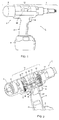
- an electric blind rivet setting device 1 has a mechanism for setting blind rivets and comprises a blind rivet setting mechanism 2 accommodated in a substantially cylindrically shaped housing and a handle 3 extending so as to be hanging substantially perpendicular from a middle position of this setting mechanism 2.
- a battery is attached so as to be attachable and detachable to a battery holding section 5 at the bottom end of the handle 3.
- a trigger 6 is provided in a position adjacent to the setting mechanism 2 in the handle 3. A worker operates the setting mechanism 2 by pulling the trigger 6, and the blind rivet setting operation is carried out.
- the setting mechanism 2 is returned to the home position by releasing the pulling operation of the trigger 6, and the setting operation is released (or stopped).
- the blind rivet setting mechanism 2 comprises a nose 7 on the end of the front side (end of right side in Fig. 1 ) and a motor section 9 at the end of the rear side (end of left side in Fig. 1 ).
- a pulling head 30 ( Fig. 3 and the like) that pulls the mandrel shaft part of the blind rivet toward the back (leftward in Fig. 1 ) is provided in the nose 7, and an electric motor is accommodated in the motor section 9.
- a recovery container 10 for broken mandrel shaft parts is formed between the nose 7 and motor section 9 in a position close to the handle 3 on the upper part of the side opposite the handle 3.
- the recovery container 10 is formed in a semicircular cylindrical shape and is surrounded by a transparent or semi-transparent cover 11.
- the cover 11 allows the mandrill shaft parts that are held to be seen from the outside and is formed so as to be openable and closable such that they may be disposed of.
- a drive force transfer and control section 11 is provided in a part other than the recovery container 10 between the motor section 9 and the nose 7.
- a mechanism for transferring the rotational force (torque) of an electric motor 13 in the motor section 9 to a spindle 14, which is a rotating shaft inside the nose 7, and a control mechanism that controls the pulling operation of the trigger and the rotation of the electric motor 13 by the release operation thereof and controls the forward movement and backward movement of the pulling head in the nose 7 through the rotation of the spindle 14 are provided.
- the electric blind rivet setting device 1 sets blind rivets with an electric motor that has a battery as the power source. Therefore, operation does not require a fluid supply tube for compressed air or the like and is released from the troublesome operations accompanying pulling around a fluid supply tube.
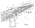
- a blind rivet B to be set in members to be riveted such as automotive body panels, attached components and the like by the electric blind rivet setting device 1 is held in the nose 7 in Fig. 3 .
- the blind rivet B comprises a rod shaped mandrel M and a hollow cylindrically shaped rivet body R.
- the rivet body R comprises a cylindrical sleeve and a flange with a diameter larger than the cylindrical sleeve formed at one end of the cylindrical sleeve.
- the mandrel M is formed from a rod shaped body that passes through the rivet body and extends lengthwise from the flange and comprises a shaft part that passes through the flange of the rivet body R and has a part gripped in the nose 7 and a mandrel head H formed with a diameter larger than the inside diameter of the cylindrical sleeve and disposed so as to extend from the other end of the cylindrical sleeve.
- the grippable part of the mandrel shaft part of the blind rivet B is inserted into the nose 7 of the blind rivet setting device 1 and held in the blind rivet setting device in a state such that the rivet body R and mandrel head H extend from the nose.
- the sleeve of the rivet body R of the blind rivet B held in the blind rivet setting device 1 is inserted into an attachment hole in the members being riveted until it contacts the surface of a member being riveted, such as an automotive body panel or attached component.
- a member being riveted such as an automotive body panel or attached component.
- the mandrel shaft part is pulled by the blind rivet setting device 1, and the mandrel head H expands and deforms part of the rivet body R sleeve.
- the members being riveted are strongly sandwiched between this expanded and deformed sleeve part and the flange.
- the rivet body is set in the members being riveted and the automotive body panel, component and the like are secured by the plurality of members being riveted, such as an automotive body panel, a component or the like, being strongly sandwiched to each other between the sleeve part that has been expanded and deformed and the flange part.
- the blind rivet B is formed from a metal material such as steel, aluminum or the like. After the blind rivet has been set, the broken mandrel shaft part must be separated and recovered.
- a drive shaft 18 is provided in the space beneath the recovery container 10 between the motor gear 15 and the spindle gear 17, in a direction front and back (that is, the axial direction) to the blind rivet setting mechanism 2, supported in the direction parallel to the axial line of the motor shaft of the electric motor 13 and the spindle 14 and supported so as to be rotatable around the axis.
- a rear gear 19 that is mated to the motor gear 15 is attached at the back end of the drive shaft 18, and a front gear 21 that is mated to the spindle gear 17 is attached at the front end of the drive shaft 18.
- the drive shaft 18 is rotated in reverse when there is positive rotation of the electric motor 13, and because the front gear 21 is mated to the spindle gear 17, the reverse rotated drive shaft 18 gives the spindle 14 a positive rotation. Therefore, the spindle 14 rotates in the same direction as the electric motor 13.
- the gear ratios for the motor gear 15 and rear gear 19 and for the front gear 21 and spindle gear 17 may be set freely according to a balance of the electric motor 13 output and blind rivet setting force.
- the drive force transfer and control section 11 also has a control mechanism that controls the positive rotation, stopping and reverse rotation of the electric motor 13 according to the pulling operation of the trigger 6 and the release operation thereof. As described above, the rotation of the electric motor 13 is transferred to the spindle 14 through the drive shaft 18.
- the control mechanism responds to a pulling operation of the trigger 6 and a release operation thereof, and by controlling the electric motor 13, the pulling head 30 in the nose 7 is moved backward from the home position (front end position) to a back end position that breaks the mandrel shaft part of the blind rivet. It is stopped at that back end position, and by releasing the pulling operation on the trigger 6, it moves forward from the back end position returning to the home position at the front end position. As is shown in Fig. 2 and Fig.
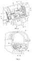
- the drive shaft 18 is formed with external threads on the circumferential surface, and two collars, a first collar 22 and a second collar 23, each formed with internal threads are screwed onto the drive shaft 18 with a space between them on the drive shaft 18.
- the first collar 22 and the second collar 23 are slidable in the axial direction of the drive shaft 18 with respect to the bottom wall of the recovery container 10, but are restricted such that they do not rotate with the rotation of the drive shaft 18.
- the two collars 22, 23 move forward together following the peaks of the threads on the drive shaft 18 because of this restriction when the drive shaft 18 is rotated in reverse by the positive rotation of the electric motor 13 (through the motor gear 15 and the rear gear 19).
- a first microswitch 25 is affixed to a tool housing 27 (or a member affixed to the tool housing 27) as a first sensor adjacent to the first collar 22, and a second microswitch 26 is affixed to the tool housing 27 (or a member affixed to the tool housing 27) as a second sensor adjacent to the second collar 23.
- the nose 7 occupies the front half of the blind rivet setting mechanism 2 in front of the recovery container 10. As is shown in Fig. 3 , the shaft center of the nose 7 is formed hollow and receives and holds the mandrel M of the blind rivet B. Furthermore, the broken mandrel shaft parts are sent to the recovery container 10.
- the nose 7 is provided on the front end side of the blind rivet setting mechanism 2, and jaws 29, as the means for gripping the mandrel M, the pulling head 30 enveloping the jaws 29 and also extending to the tool housing 27 and being movable in the axial direction of the blind rivet setting mechanism 2 so as to pull the jaws 29 to the rear side, the spindle 14, which is disposed on the rear side of the pulling head 30 and is the drive means for pulling the jaws 29 gripping the mandrel M to the rear, and a rotary motion/linear motion conversion mechanism, which converts the rotary motion of the spindle 14 to linear motion, are provided.
- the pulling head 30 is moved linearly by the rotary motion/linear motion conversion mechanism, and the jaws 29 are pulled toward the back of the nose and returned toward the front of the nose.
- the shaft part of the mandrel M that is gripped by the jaws 29 is pulled with enough strength by the linear motion of the pulling head 30 toward the rear that it breaks at the breakable part.
- the mandrel head H expands and deforms part of the sleeve of the rivet body R, and the members being riveted are sandwiched firmly between that expanded and deformed sleeve part and the flange.
- the blind rivet B is set and secured in the members being riveted.
- the nose 7 also has a tip nose piece 31 and a nose housing 33 extending in a cylindrical shape from the nose piece 31 toward the tool housing 27 and affixed to the tool housing 27.
- the cylindrically shaped pulling head 30 is accommodated inside of the nose housing 33 so as to be slidable in the axial direction (forward and backward directions) with respect to the nose housing 33.
- the jaws 29 are disposed such that the tip thereof is in contact with the back end of the nose piece 31, are formed in a narrowing tip shape toward the nose piece 31 and are accommodated in a cavity of the pulling head 30 that narrows toward the tip.
- the jaws 29 are divided into 2 to 4 pieces in the circumferential direction inside the cylindrically shaped pulling head 30 and are assembled to a cylindrical body in the hollow of the cavity at the axial center of the pulling head 30. They receive the mandrel M of the blind rivet B inserted from the nose piece 31, and hold the shaft part of the mandrel M so that it is not released.
- the pulling head 30 has a pin 37 received so as to be slidable in an axially directed (front and back direction) slit 35 in a mast housing 34 affixed to the tool housing 27 and extending forward from the tool housing 27. Because of the slit 35 and pin 37, the pulling head 30 (and the jaws 29) are slidable in the axial direction inside the mast housing 34 and the tool housing 27 but cannot rotate around the axis.
- Internal threads are formed on a circular gear 44 affixed to the spindle 14. The external threads of a screw member 38 are screwed into these internal threads.
- the screw member 38 is affixed to the pulling head 30 and extends backward on the inside of the mast housing 34 that is affixed to the tool housing 27. As is shown in Fig. 5 , the screw member 38 is screwed into the inside of the circular gear 44 that is affixed to the spindle 14; therefore, positive rotation of the spindle 14 that cannot move in the axial direction is converted to backward motion that pulls the screw member 38 toward the rear, and reverse rotation of the spindle 14 is converted into forward motion that returns the screw member 38 toward the front.
- the screw member 38 pulls the mandrel M of the blind rivet B toward the recovery container 10 as in arrow 41 because of the positive rotation of arrow 39 in Fig. 5 .
- the axial center part of the jaws 29, the axial center part of the pulling head 30, the axial center part of the screw member 38 and the axial center part of the spindle 14 form a continuous hollow passage from the opening of the nose 7 to the opening of the recovery container 10. Therefore, the shaft part of a mandrel M is inserted into the jaws 29, and a broken mandrel shaft part 43 is fed into the recovery container 10 as in arrow 45 in Fig. 3 .
- the feeding of the broken mandrel shaft part is carried out by the broken mandrel shaft parts that are fed into the hollow passage one after another pushing the previous broken mandrel shaft parts (a so-called push out system).
- a so-called push out system a so-called push out system
- an o-ring 46 and a steel ball 47 are provided so as to obstruct part of the hollow passage in the opening part of the nose piece 31, and the insertion of the mandrel M of blind rivet B is allowed, but the broken mandrel shaft part 43 is prevented from being discharged to the outside from the nose piece 31.
- the recovery container 10 for recovering the broken mandrel shaft parts after blind rivet setting is formed in a position in proximity to the handle 3 between the nose 7 and the motor section 9.
- the handle 3 extends from the position of this recovery container 10 downward at a slant such that the blind rivet setting device 1 is easily gripped by a worker.
- the recovery container 10 is disposed in a middle position in the tool housing 27; therefore, there is no need to install a mandrel collector at the back end of the tool housing as in JP-A 2003-266143 , and there is no instability when held by hand by a worker because of the weight of the electric motor and operation as in EP 527 414 B1 .
- the drive force transfer and control section 11 which is an important part of the electric blind rivet setting device 1 according to the present invention will be described with reference to Fig. 6 through Fig. 10 .
- the drive force transfer and control section 11 transfers the rotational force from the electric motor 13 in the motor section 9 to the spindle 14 in the nose 7, circumventing the space occupied (blind rivet setting mechanism 2) by the recovery container 10.
- the drive force transfer and control section 11 also controls the positive rotation, stopping and reverse rotation of the electric motor 13 according to the pulling operation of the trigger 6 and the release operation thereof.
- the drive shaft 18 is formed with threads on the circumferential surface, and two collars, the first collar 22 and the second collar 23, formed with internal threads are screwed onto the drive shaft 18.
- the first collar 22 and the second collar 23 are formed in an elliptical cylindrical shape having a flat surface on the top and bottom, and that flat surface is disposed so as to be slidable underneath the recovery container 10.
- the two collars 22 and 23 are restricted such that they do not rotate with the axial rotation of the drive shaft 18. Therefore, the two collars 22, 23 move forward together (arrow 50 in Fig.
- the first microswitch 25 is affixed to the tool housing 27 (or a member affixed to the tool housing 27) as a first sensor adjacent to the first collar 22, and the second microswitch 26 is affixed to the tool housing 27 (or a member affixed to the tool housing 27) as a second sensor adjacent to the second collar 23.
- the first microswitch 25 is turned on and off
- the second collar 23 moves along the drive shaft 18, the second microswitch 26 is turned off and on.
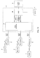
- control circuit 55 which is the control means, in Fig. 10
- an on/off signal is input from the first microswitch 25 which is turned on and off by the first collar 22, an on/off signal input from the second microswitch 26 which is turned on and off by the second collar 23 and an on/off signal of the trigger switch 49 input by the pulling operation of the trigger 6 and the release thereof.
- a signal processing section 55A that receives the on/off signal from the first microswitch 25, the on/off signal from the second microswitch 26 and the on/off signal of the trigger switch 49 and outputs a positive rotation signal, stop signal and reverse rotation signal for positive rotation, stopping and reverse rotation of the electric motor 13 is provided in the control circuit 55.
- the pulling head 30 Before the electric motor 13 is supplied with electric power from the battery 51, the pulling head 30 is positioned in the home position (position in Fig. 3 ) on the front end side of the blind rivet setting mechanism 2 by a coil spring 42 ( Fig. 5 ).
- the first collar 22 pushes a switch lever 53 of the first microswitch 25 and an on signal is output by the first microswitch 25.
- the second collar 22 does not push a switch lever 54 of the second microswitch 26, so an off signal is output by the second microswitch 26.
- the pulling head 30 (jaws 29) is in the home position when an on signal is output by the first microswitch 25 and an off signal is output by the second microswitch 26. Even if electric power is supplied to the electric motor 13 from the battery 51, the operation of the electric motor 13 is stopped as long as the trigger 6 is not operated.
- the first microswitch 25 outputs an on signal
- the second microswitch 26 outputs an off signal.
- the control circuit recognizes that the setting device 1 is in the home position state through an off signal from the trigger switch 49 of the trigger 6, an on signal from the first microswitch 25 and an off signal from the second microswitch 26.
- the signal processing section 55A of the control circuit 55 provided in the electric blind rivet setting device 1 outputs a positive rotation signal that rotates the electric motor 13 positively.
- the driver 55B that has received the positive rotation signal sends electric power from the battery 51 to the electric motor 13 and causes positive rotation.
- the positive rotation of the electric motor 13 is transferred to the spindle 14 through the motor gear 15, rear gear 19, drive shaft 18, front gear 21 and spindle gear 17, and the spindle rotates positively.
- the positive rotation of the spindle 14 rotates the screw member 38 ( Fig.
- the rivet body is set in the members being riveted and an automotive body panel, component, and the like are secured by a plurality of members being riveted, such as an automotive body panel, a component or the like, being strongly sandwiched to each other between the sleeve part that has been expanded and deformed and the flange part.
- the positive rotation of the electric motor 13 rotates the drive shaft 18 in reverse because of the motor gear 15 and the rear gear 19, and as is shown by the arrow 50 in Fig. 6 , the first collar 22 and the second collar 23 move forward.
- the rotation of the drive shaft 18 moves the pulling head 30 in the axial direction and also moves the first collar 22 and the second collar 23; therefore, the position of the pulling head 30 in the axial direction is detected by the first microswitch 25 and the second microswitch 26 that are turned on and off by the first collar 22 and the second collar 23.
- the switch lever 53 of the first microswitch 25 is pushed in, and the on signal of the first microswitch 25 is changed to an off signal.
- the second collar 23 moves with the first collar 22, and when the pulling head 30 moves to the back end position, which is the breaking position for the mandrel shaft part, the second collar 23 pushes the switch lever 54 of the second microswitch 26, and the off signal of the second microswitch 26 changes to an on signal.
- the trigger 6 is still being operated by pulling, so an on signal is output by the trigger switch 49.
- the pulling head 30 In a state where an on signal is output by the trigger switch 49, the pulling head 30 (jaws 29) is in the back end position on the furthest back side when an off signal is output by the first microswitch and an on signal is output by the second microswitch 30.
- the signal processing section 55A of the control circuit 55 receives the on signal from the trigger switch 49, the off signal from the first microswitch 25 and the on signal from the second microswitch 26 and outputs a stop signal.
- the driver 55B receives the stop signal and stops the rotation of the electric motor 13 (stops by brake operation, stops by regenerative braking or the like). With the stopping of the electric motor 13, the rotation of the spindle 14 also stops, and the pulling head 30 (jaws 29) is stopped at the back end position.
- the on signal from the from the trigger switch 49 of the trigger 6 disappears (or an off signal is output).
- the signal processing section 55A of the control circuit 55 receives the off signal from the trigger switch 49, the off signal from the first microswitch 25 and the on signal from the second microswitch 26 and outputs a reverse rotation signal.
- the driver 55B that receives the reverse rotation signal rotates the electric motor 13 in reverse.
- the spindle 14 is rotated in reverse by the reverse rotation of the electric motor 13, the screw member 38 rotated in reverse and the pulling head 30 (jaws 29) is moved from the back end position toward the home position at the front end.
- the drive shaft 18 is rotated positively, and the first collar 22 and the second collar 23 move in the direction opposite of the arrow 50 in Fig. 6 . Therefore, the second collar 23 is separated from the second microswitch 26, and an off signal is output by the second microswitch 26.
- the first collar 22 approaches the first microswitch 25, and when the pulling head 30 returns to the home position, the first collar 22 pushes the switch lever 53 of the first microswitch 25, and an on signal is output by the first microswitch 25.
- this state is the state before operation of the blind rivet setting device 1 began.
- the control circuit 55 keeps the electric motor 13 in a non-operating state. Therefore, the operation of the electric motor 13 is stopped, and the pulling head 30 is in the home position.
- the first collar 22 and the second collar 23 move forward along the drive shaft 18.
- An off signal is output by the first microswitch 25.
- the signal processing section 55A of the control circuit 55 receives the off signal from the first microswitch 25, the off signal from the second microswitch 26 and the off signal from the trigger switch 49 of the trigger 6.
- a reverse rotation signal is sent to the driver 55B, and the driver 55B rotates the electric motor 13 in reverse.
Landscapes
- Engineering & Computer Science (AREA)
- Mechanical Engineering (AREA)
- Insertion Pins And Rivets (AREA)
- Operating, Guiding And Securing Of Roll- Type Closing Members (AREA)
- Blinds (AREA)
Applications Claiming Priority (1)
| Application Number | Priority Date | Filing Date | Title |
|---|---|---|---|
| JP2010087788A JP5597432B2 (ja) | 2010-04-06 | 2010-04-06 | 電動ブラインドリベット締結装置 |
Publications (3)
| Publication Number | Publication Date |
|---|---|
| EP2374558A2 EP2374558A2 (en) | 2011-10-12 |
| EP2374558A3 EP2374558A3 (en) | 2015-03-11 |
| EP2374558B1 true EP2374558B1 (en) | 2016-08-31 |
Family
ID=44117421
Family Applications (1)
| Application Number | Title | Priority Date | Filing Date |
|---|---|---|---|
| EP11161091.1A Active EP2374558B1 (en) | 2010-04-06 | 2011-04-05 | Electric blind rivet setting device |
Country Status (5)
| Country | Link |
|---|---|
| US (2) | US8443512B2 (zh) |
| EP (1) | EP2374558B1 (zh) |
| JP (1) | JP5597432B2 (zh) |
| KR (1) | KR101796793B1 (zh) |
| CN (1) | CN102233402B (zh) |
Families Citing this family (37)
| Publication number | Priority date | Publication date | Assignee | Title |
|---|---|---|---|---|
| JP5874967B2 (ja) * | 2011-12-08 | 2016-03-02 | ポップリベット・ファスナー株式会社 | ブラインドリベット締結工具 |
| JP5674691B2 (ja) | 2012-02-23 | 2015-02-25 | 株式会社ロブテックス | 電動リベッター |
| US9968988B2 (en) | 2012-05-31 | 2018-05-15 | Newfrey Llc | Blind rivet fastening device |
| JP5928803B2 (ja) * | 2012-05-31 | 2016-06-01 | ポップリベット・ファスナー株式会社 | ブラインドリベット締結装置 |
| US10464122B2 (en) * | 2012-07-13 | 2019-11-05 | Atlas Copco Ias Uk Limited | Spot-joining apparatus and methods |
| TWI477331B (zh) * | 2013-08-09 | 2015-03-21 | Tranmax Machinery Co Ltd | Electromotive pull nail gun with pre - tensioned nail and its operation method |
| USD775505S1 (en) * | 2013-12-11 | 2017-01-03 | Hilti Aktiengesellschaft | Powder actuated tool |
| EP2910321B1 (de) * | 2014-02-24 | 2018-10-17 | GESIPA Blindniettechnik GmbH | Blindnietsetzgerät |
| TWI580494B (zh) * | 2014-04-11 | 2017-05-01 | Electric pull cap gun and its control device | |
| US9440340B2 (en) * | 2014-06-11 | 2016-09-13 | Techway Industrial Co., Ltd. | Electric rivet nut tool and control device thereof |
| EP2985093B1 (de) * | 2014-08-15 | 2019-05-29 | GESIPA Blindniettechnik GmbH | Blindnietsetzgerät und Verfahren zum Setzen eines Blindniets |
| US9527129B2 (en) * | 2014-09-18 | 2016-12-27 | Li-Su Chen | Riveting tool |
| USD778134S1 (en) * | 2014-10-20 | 2017-02-07 | Avdel Uk Limited | Insertion tool |
| USD752936S1 (en) * | 2014-10-20 | 2016-04-05 | Avdel Uk Limited | Rivet setting tool |
| USD781121S1 (en) * | 2014-10-20 | 2017-03-14 | Avdel Uk Limited | Rivet setting tool |
| USD787103S1 (en) * | 2014-12-16 | 2017-05-16 | Atlas Copco Industrial Technique Ab | Lamp portion of an electric driver tool |
| DE102015122374B4 (de) * | 2015-12-21 | 2023-12-07 | Honsel Distribution Gmbh & Co. Kg | Verfahren zum Betrieb eines handhaltbaren Nietgerätes und handhaltbares Nietgerät |
| USD811184S1 (en) * | 2016-10-07 | 2018-02-27 | Yuyao Tangwen Tool Co., Ltd. | T-shaped single-handed rivet gun |
| USD811185S1 (en) * | 2016-10-09 | 2018-02-27 | Yuyao Tangwen Tool Co., Ltd. | Folding rivet gun |
| JP1583277S (zh) * | 2016-11-07 | 2017-08-07 | ||
| EP3563946B1 (en) * | 2016-12-28 | 2021-11-03 | Makita Corporation | Fastening tool |
| USD860746S1 (en) * | 2017-06-16 | 2019-09-24 | Atlas Copco Ias Uk Limited | Riveting device |
| JP6768998B2 (ja) * | 2017-06-19 | 2020-10-14 | 株式会社マキタ | 締結工具 |
| US10483901B2 (en) | 2017-07-10 | 2019-11-19 | Newfrey Llc | System and method for installation and verification of fasteners |
| JP1600283S (zh) * | 2017-09-01 | 2018-03-26 | ||
| CN109954829A (zh) * | 2017-12-22 | 2019-07-02 | 车王电子股份有限公司 | 拉钉机的控制方法 |
| CN108746459A (zh) * | 2018-07-21 | 2018-11-06 | 上海安字实业有限公司 | 双向柔性触动的电动铆接工具 |
| CN109396319B (zh) * | 2018-07-27 | 2024-04-05 | 宾科精密部件(中国)有限公司 | 压铆装置 |
| CN108903772B (zh) * | 2018-08-02 | 2024-03-08 | 天佑电器(苏州)有限公司 | 盖体组件及具有其的吸尘器 |
| US11673243B2 (en) | 2018-09-05 | 2023-06-13 | Milwaukee Electric Tool Corporation | Blind rivet nut-setting tool |
| CN109226536B (zh) * | 2018-09-10 | 2024-04-26 | 深圳市双环全新机电股份有限公司 | 微电机自动装配机 |
| US11396038B2 (en) * | 2019-09-06 | 2022-07-26 | Makita Corporation | Fastening tool |
| USD934645S1 (en) * | 2019-10-17 | 2021-11-02 | Atlas Copco Industrial Technique Ab | Power tool |
| USD931700S1 (en) | 2019-10-17 | 2021-09-28 | Atlas Copco Industrial Technique Ab | Power tool |
| JP1671615S (zh) * | 2020-03-11 | 2020-11-02 | ||
| US11654475B2 (en) | 2020-06-03 | 2023-05-23 | Milwaukee Electric Tool Corporation | Rivet setting tool |
| TWI745048B (zh) * | 2020-08-25 | 2021-11-01 | 朝程工業股份有限公司 | 電動拉帽機 |
Family Cites Families (22)
| Publication number | Priority date | Publication date | Assignee | Title |
|---|---|---|---|---|
| US3033410A (en) * | 1957-07-10 | 1962-05-08 | Illinois Tool Works | Rivet setter |
| US3095106A (en) * | 1961-12-28 | 1963-06-25 | United Shoe Machinery Corp | Automatic rivet setting tools |
| JPS4941975A (zh) * | 1972-08-30 | 1974-04-19 | ||
| GB1596304A (en) * | 1977-03-22 | 1981-08-26 | Avdel Ltd | Collector for broken-off fastener parts |
| US4178869A (en) * | 1978-04-27 | 1979-12-18 | Turrentine Fred C | Combined removable tiller extension holding and controlling device for watercraft |
| JPS59153538A (ja) * | 1983-02-21 | 1984-09-01 | Katsuyuki Totsu | 電動リベツト工具 |
| EP0201293B1 (en) * | 1985-05-10 | 1989-07-26 | Avdel Systems Limited | Breakstem fastener installation tool |
| DE3532932A1 (de) * | 1985-09-14 | 1987-03-19 | Schwab Maschbau | Nietsetzwerkzeug |
| DE4126602A1 (de) | 1991-08-12 | 1993-02-18 | Gesipa Blindniettechnik | Blindnietgeraet |
| DE4406946C2 (de) * | 1994-03-04 | 1998-11-19 | Gesipa Blindniettechnik | Blindnietmutter-Setzgerät |
| AU4055995A (en) * | 1995-02-15 | 1996-08-22 | World Wide Product Development Company Limited | Power operated self-drilling rivet setting tool |
| DE10011340A1 (de) * | 2000-03-10 | 2001-09-20 | Gesipa Blindniettechnik | Pneumatisch-hydraulisches Blindnietgerät |
| US7024741B2 (en) * | 2001-06-27 | 2006-04-11 | Newfrey Llc | Fastening structure with a rivet |
| JP4112251B2 (ja) * | 2002-03-14 | 2008-07-02 | 株式会社ロブテックス | 作動工具 |
| US6704986B1 (en) * | 2003-04-16 | 2004-03-16 | Pao-Fang Liu | Air over oil riveter with rotatable head piece |
| JP2006187787A (ja) * | 2005-01-06 | 2006-07-20 | Nippon Pop Rivets & Fasteners Ltd | ブラインドリベット締結装置 |
| DE102005054719B3 (de) * | 2005-11-17 | 2007-05-03 | A. Raymond Et Cie | Vorrichtung zum Setzen von Befestigungselementen |
| GB2442448B (en) * | 2006-10-03 | 2009-02-18 | Textron Fastening Syst Ltd | Improved stem collection containers for fastening tools |
| JP4767181B2 (ja) * | 2007-01-12 | 2011-09-07 | 株式会社ナカボーテック | リベット締結装置 |
| KR100887541B1 (ko) * | 2007-03-14 | 2009-03-09 | 이수일 | 셀프 드릴링 및 자동 인발을 위한 리벳팅용 전동공구 |
| TW201021938A (en) * | 2008-12-09 | 2010-06-16 | Tranmax Machinery Co Ltd | Riveting tool having rivet stem removal function |
| JP2010260064A (ja) * | 2009-04-30 | 2010-11-18 | Nippon Pop Rivets & Fasteners Ltd | ブラインドリベット締結装置 |
-
2010
- 2010-04-06 JP JP2010087788A patent/JP5597432B2/ja active Active
-
2011
- 2011-04-01 KR KR1020110030006A patent/KR101796793B1/ko active IP Right Grant
- 2011-04-02 CN CN201110084047.7A patent/CN102233402B/zh active Active
- 2011-04-04 US US13/079,246 patent/US8443512B2/en not_active Ceased
- 2011-04-05 EP EP11161091.1A patent/EP2374558B1/en active Active
-
2015
- 2015-05-12 US US14/709,809 patent/USRE46857E1/en active Active
Also Published As
| Publication number | Publication date |
|---|---|
| EP2374558A2 (en) | 2011-10-12 |
| US20110239449A1 (en) | 2011-10-06 |
| CN102233402B (zh) | 2015-07-22 |
| EP2374558A3 (en) | 2015-03-11 |
| KR20110112209A (ko) | 2011-10-12 |
| JP2011218381A (ja) | 2011-11-04 |
| KR101796793B1 (ko) | 2017-11-10 |
| US8443512B2 (en) | 2013-05-21 |
| CN102233402A (zh) | 2011-11-09 |
| JP5597432B2 (ja) | 2014-10-01 |
| USRE46857E1 (en) | 2018-05-22 |
Similar Documents
| Publication | Publication Date | Title |
|---|---|---|
| EP2374558B1 (en) | Electric blind rivet setting device | |
| EP2855046B1 (en) | Blind rivet fastening device | |
| US9968988B2 (en) | Blind rivet fastening device | |
| JP2010260064A (ja) | ブラインドリベット締結装置 | |
| EP3689548B1 (en) | A blind nut fastening apparatus | |
| EP3643424B1 (en) | Fastening tool | |
| JP2011218381A5 (zh) | ||
| US20080012453A1 (en) | Motor having a hollow drive shaft | |
| WO2018139372A1 (ja) | 締結工具 | |
| JP6748573B2 (ja) | 締結工具 | |
| EP0456269A2 (en) | Riveter | |
| JP6716844B2 (ja) | 締結工具 | |
| EP0000626B1 (en) | Pull-type fastener-setting tool | |
| EP0468717B1 (en) | Blind riveting tool | |
| US4189933A (en) | Hand operated lockbolt setting tool | |
| US3399561A (en) | Portable rivet setting tool | |
| JP3681615B2 (ja) | リベッター | |
| JP2021041419A (ja) | 締結工具 | |
| JP2020075345A (ja) | 電動工具 | |
| JPH0141445B2 (zh) |
Legal Events
| Date | Code | Title | Description |
|---|---|---|---|
| PUAI | Public reference made under article 153(3) epc to a published international application that has entered the european phase |
Free format text: ORIGINAL CODE: 0009012 |
|
| AK | Designated contracting states |
Kind code of ref document: A2 Designated state(s): AL AT BE BG CH CY CZ DE DK EE ES FI FR GB GR HR HU IE IS IT LI LT LU LV MC MK MT NL NO PL PT RO RS SE SI SK SM TR |
|
| AX | Request for extension of the european patent |
Extension state: BA ME |
|
| PUAL | Search report despatched |
Free format text: ORIGINAL CODE: 0009013 |
|
| AK | Designated contracting states |
Kind code of ref document: A3 Designated state(s): AL AT BE BG CH CY CZ DE DK EE ES FI FR GB GR HR HU IE IS IT LI LT LU LV MC MK MT NL NO PL PT RO RS SE SI SK SM TR |
|
| AX | Request for extension of the european patent |
Extension state: BA ME |
|
| RIC1 | Information provided on ipc code assigned before grant |
Ipc: B21J 15/06 20060101ALI20150203BHEP Ipc: B21J 15/32 20060101ALI20150203BHEP Ipc: B21J 15/26 20060101ALI20150203BHEP Ipc: B21J 15/10 20060101ALI20150203BHEP Ipc: B21J 15/04 20060101AFI20150203BHEP |
|
| 17P | Request for examination filed |
Effective date: 20150806 |
|
| RBV | Designated contracting states (corrected) |
Designated state(s): AL AT BE BG CH CY CZ DE DK EE ES FI FR GB GR HR HU IE IS IT LI LT LU LV MC MK MT NL NO PL PT RO RS SE SI SK SM TR |
|
| RAP1 | Party data changed (applicant data changed or rights of an application transferred) |
Owner name: NEWFREY LLC |
|
| GRAP | Despatch of communication of intention to grant a patent |
Free format text: ORIGINAL CODE: EPIDOSNIGR1 |
|
| INTG | Intention to grant announced |
Effective date: 20160422 |
|
| INTG | Intention to grant announced |
Effective date: 20160502 |
|
| GRAS | Grant fee paid |
Free format text: ORIGINAL CODE: EPIDOSNIGR3 |
|
| GRAA | (expected) grant |
Free format text: ORIGINAL CODE: 0009210 |
|
| AK | Designated contracting states |
Kind code of ref document: B1 Designated state(s): AL AT BE BG CH CY CZ DE DK EE ES FI FR GB GR HR HU IE IS IT LI LT LU LV MC MK MT NL NO PL PT RO RS SE SI SK SM TR |
|
| REG | Reference to a national code |
Ref country code: CH Ref legal event code: EP Ref country code: GB Ref legal event code: FG4D |
|
| REG | Reference to a national code |
Ref country code: IE Ref legal event code: FG4D |
|
| REG | Reference to a national code |
Ref country code: AT Ref legal event code: REF Ref document number: 824547 Country of ref document: AT Kind code of ref document: T Effective date: 20161015 |
|
| REG | Reference to a national code |
Ref country code: DE Ref legal event code: R096 Ref document number: 602011029756 Country of ref document: DE |
|
| REG | Reference to a national code |
Ref country code: LT Ref legal event code: MG4D |
|
| REG | Reference to a national code |
Ref country code: NL Ref legal event code: MP Effective date: 20160831 |
|
| REG | Reference to a national code |
Ref country code: AT Ref legal event code: MK05 Ref document number: 824547 Country of ref document: AT Kind code of ref document: T Effective date: 20160831 |
|
| PG25 | Lapsed in a contracting state [announced via postgrant information from national office to epo] |
Ref country code: RS Free format text: LAPSE BECAUSE OF FAILURE TO SUBMIT A TRANSLATION OF THE DESCRIPTION OR TO PAY THE FEE WITHIN THE PRESCRIBED TIME-LIMIT Effective date: 20160831 Ref country code: NO Free format text: LAPSE BECAUSE OF FAILURE TO SUBMIT A TRANSLATION OF THE DESCRIPTION OR TO PAY THE FEE WITHIN THE PRESCRIBED TIME-LIMIT Effective date: 20161130 Ref country code: HR Free format text: LAPSE BECAUSE OF FAILURE TO SUBMIT A TRANSLATION OF THE DESCRIPTION OR TO PAY THE FEE WITHIN THE PRESCRIBED TIME-LIMIT Effective date: 20160831 Ref country code: LT Free format text: LAPSE BECAUSE OF FAILURE TO SUBMIT A TRANSLATION OF THE DESCRIPTION OR TO PAY THE FEE WITHIN THE PRESCRIBED TIME-LIMIT Effective date: 20160831 Ref country code: FI Free format text: LAPSE BECAUSE OF FAILURE TO SUBMIT A TRANSLATION OF THE DESCRIPTION OR TO PAY THE FEE WITHIN THE PRESCRIBED TIME-LIMIT Effective date: 20160831 |
|
| PG25 | Lapsed in a contracting state [announced via postgrant information from national office to epo] |
Ref country code: NL Free format text: LAPSE BECAUSE OF FAILURE TO SUBMIT A TRANSLATION OF THE DESCRIPTION OR TO PAY THE FEE WITHIN THE PRESCRIBED TIME-LIMIT Effective date: 20160831 Ref country code: LV Free format text: LAPSE BECAUSE OF FAILURE TO SUBMIT A TRANSLATION OF THE DESCRIPTION OR TO PAY THE FEE WITHIN THE PRESCRIBED TIME-LIMIT Effective date: 20160831 Ref country code: AT Free format text: LAPSE BECAUSE OF FAILURE TO SUBMIT A TRANSLATION OF THE DESCRIPTION OR TO PAY THE FEE WITHIN THE PRESCRIBED TIME-LIMIT Effective date: 20160831 Ref country code: GR Free format text: LAPSE BECAUSE OF FAILURE TO SUBMIT A TRANSLATION OF THE DESCRIPTION OR TO PAY THE FEE WITHIN THE PRESCRIBED TIME-LIMIT Effective date: 20161201 Ref country code: SE Free format text: LAPSE BECAUSE OF FAILURE TO SUBMIT A TRANSLATION OF THE DESCRIPTION OR TO PAY THE FEE WITHIN THE PRESCRIBED TIME-LIMIT Effective date: 20160831 Ref country code: ES Free format text: LAPSE BECAUSE OF FAILURE TO SUBMIT A TRANSLATION OF THE DESCRIPTION OR TO PAY THE FEE WITHIN THE PRESCRIBED TIME-LIMIT Effective date: 20160831 |
|
| REG | Reference to a national code |
Ref country code: FR Ref legal event code: PLFP Year of fee payment: 7 |
|
| PG25 | Lapsed in a contracting state [announced via postgrant information from national office to epo] |
Ref country code: RO Free format text: LAPSE BECAUSE OF FAILURE TO SUBMIT A TRANSLATION OF THE DESCRIPTION OR TO PAY THE FEE WITHIN THE PRESCRIBED TIME-LIMIT Effective date: 20160831 Ref country code: EE Free format text: LAPSE BECAUSE OF FAILURE TO SUBMIT A TRANSLATION OF THE DESCRIPTION OR TO PAY THE FEE WITHIN THE PRESCRIBED TIME-LIMIT Effective date: 20160831 |
|
| PG25 | Lapsed in a contracting state [announced via postgrant information from national office to epo] |
Ref country code: SK Free format text: LAPSE BECAUSE OF FAILURE TO SUBMIT A TRANSLATION OF THE DESCRIPTION OR TO PAY THE FEE WITHIN THE PRESCRIBED TIME-LIMIT Effective date: 20160831 Ref country code: BG Free format text: LAPSE BECAUSE OF FAILURE TO SUBMIT A TRANSLATION OF THE DESCRIPTION OR TO PAY THE FEE WITHIN THE PRESCRIBED TIME-LIMIT Effective date: 20161130 Ref country code: PT Free format text: LAPSE BECAUSE OF FAILURE TO SUBMIT A TRANSLATION OF THE DESCRIPTION OR TO PAY THE FEE WITHIN THE PRESCRIBED TIME-LIMIT Effective date: 20170102 Ref country code: BE Free format text: LAPSE BECAUSE OF FAILURE TO SUBMIT A TRANSLATION OF THE DESCRIPTION OR TO PAY THE FEE WITHIN THE PRESCRIBED TIME-LIMIT Effective date: 20160831 Ref country code: DK Free format text: LAPSE BECAUSE OF FAILURE TO SUBMIT A TRANSLATION OF THE DESCRIPTION OR TO PAY THE FEE WITHIN THE PRESCRIBED TIME-LIMIT Effective date: 20160831 Ref country code: SM Free format text: LAPSE BECAUSE OF FAILURE TO SUBMIT A TRANSLATION OF THE DESCRIPTION OR TO PAY THE FEE WITHIN THE PRESCRIBED TIME-LIMIT Effective date: 20160831 Ref country code: PL Free format text: LAPSE BECAUSE OF FAILURE TO SUBMIT A TRANSLATION OF THE DESCRIPTION OR TO PAY THE FEE WITHIN THE PRESCRIBED TIME-LIMIT Effective date: 20160831 Ref country code: CZ Free format text: LAPSE BECAUSE OF FAILURE TO SUBMIT A TRANSLATION OF THE DESCRIPTION OR TO PAY THE FEE WITHIN THE PRESCRIBED TIME-LIMIT Effective date: 20160831 |
|
| REG | Reference to a national code |
Ref country code: DE Ref legal event code: R097 Ref document number: 602011029756 Country of ref document: DE |
|
| PG25 | Lapsed in a contracting state [announced via postgrant information from national office to epo] |
Ref country code: IT Free format text: LAPSE BECAUSE OF FAILURE TO SUBMIT A TRANSLATION OF THE DESCRIPTION OR TO PAY THE FEE WITHIN THE PRESCRIBED TIME-LIMIT Effective date: 20160831 |
|
| PLBE | No opposition filed within time limit |
Free format text: ORIGINAL CODE: 0009261 |
|
| STAA | Information on the status of an ep patent application or granted ep patent |
Free format text: STATUS: NO OPPOSITION FILED WITHIN TIME LIMIT |
|
| 26N | No opposition filed |
Effective date: 20170601 |
|
| PG25 | Lapsed in a contracting state [announced via postgrant information from national office to epo] |
Ref country code: SI Free format text: LAPSE BECAUSE OF FAILURE TO SUBMIT A TRANSLATION OF THE DESCRIPTION OR TO PAY THE FEE WITHIN THE PRESCRIBED TIME-LIMIT Effective date: 20160831 |
|
| REG | Reference to a national code |
Ref country code: CH Ref legal event code: PL |
|
| REG | Reference to a national code |
Ref country code: IE Ref legal event code: MM4A |
|
| PG25 | Lapsed in a contracting state [announced via postgrant information from national office to epo] |
Ref country code: MC Free format text: LAPSE BECAUSE OF FAILURE TO SUBMIT A TRANSLATION OF THE DESCRIPTION OR TO PAY THE FEE WITHIN THE PRESCRIBED TIME-LIMIT Effective date: 20160831 |
|
| PG25 | Lapsed in a contracting state [announced via postgrant information from national office to epo] |
Ref country code: LI Free format text: LAPSE BECAUSE OF NON-PAYMENT OF DUE FEES Effective date: 20170430 Ref country code: CH Free format text: LAPSE BECAUSE OF NON-PAYMENT OF DUE FEES Effective date: 20170430 Ref country code: LU Free format text: LAPSE BECAUSE OF NON-PAYMENT OF DUE FEES Effective date: 20170405 |
|
| REG | Reference to a national code |
Ref country code: FR Ref legal event code: PLFP Year of fee payment: 8 |
|
| PG25 | Lapsed in a contracting state [announced via postgrant information from national office to epo] |
Ref country code: IE Free format text: LAPSE BECAUSE OF NON-PAYMENT OF DUE FEES Effective date: 20170405 |
|
| PG25 | Lapsed in a contracting state [announced via postgrant information from national office to epo] |
Ref country code: MT Free format text: LAPSE BECAUSE OF NON-PAYMENT OF DUE FEES Effective date: 20170405 |
|
| PG25 | Lapsed in a contracting state [announced via postgrant information from national office to epo] |
Ref country code: AL Free format text: LAPSE BECAUSE OF FAILURE TO SUBMIT A TRANSLATION OF THE DESCRIPTION OR TO PAY THE FEE WITHIN THE PRESCRIBED TIME-LIMIT Effective date: 20160831 |
|
| PG25 | Lapsed in a contracting state [announced via postgrant information from national office to epo] |
Ref country code: HU Free format text: LAPSE BECAUSE OF FAILURE TO SUBMIT A TRANSLATION OF THE DESCRIPTION OR TO PAY THE FEE WITHIN THE PRESCRIBED TIME-LIMIT; INVALID AB INITIO Effective date: 20110405 |
|
| PG25 | Lapsed in a contracting state [announced via postgrant information from national office to epo] |
Ref country code: CY Free format text: LAPSE BECAUSE OF NON-PAYMENT OF DUE FEES Effective date: 20160831 |
|
| PG25 | Lapsed in a contracting state [announced via postgrant information from national office to epo] |
Ref country code: MK Free format text: LAPSE BECAUSE OF FAILURE TO SUBMIT A TRANSLATION OF THE DESCRIPTION OR TO PAY THE FEE WITHIN THE PRESCRIBED TIME-LIMIT Effective date: 20160831 |
|
| PG25 | Lapsed in a contracting state [announced via postgrant information from national office to epo] |
Ref country code: TR Free format text: LAPSE BECAUSE OF FAILURE TO SUBMIT A TRANSLATION OF THE DESCRIPTION OR TO PAY THE FEE WITHIN THE PRESCRIBED TIME-LIMIT Effective date: 20160831 |
|
| PG25 | Lapsed in a contracting state [announced via postgrant information from national office to epo] |
Ref country code: IS Free format text: LAPSE BECAUSE OF FAILURE TO SUBMIT A TRANSLATION OF THE DESCRIPTION OR TO PAY THE FEE WITHIN THE PRESCRIBED TIME-LIMIT Effective date: 20161231 |
|
| PGFP | Annual fee paid to national office [announced via postgrant information from national office to epo] |
Ref country code: FR Payment date: 20230221 Year of fee payment: 13 |
|
| PGFP | Annual fee paid to national office [announced via postgrant information from national office to epo] |
Ref country code: GB Payment date: 20230216 Year of fee payment: 13 |
|
| PGFP | Annual fee paid to national office [announced via postgrant information from national office to epo] |
Ref country code: DE Payment date: 20230222 Year of fee payment: 13 |
|
| P01 | Opt-out of the competence of the unified patent court (upc) registered |
Effective date: 20230912 |