EP2373965B2 - Method for estimating a jet temperature in a jet engine - Google Patents
Method for estimating a jet temperature in a jet engine Download PDFInfo
- Publication number
- EP2373965B2 EP2373965B2 EP09801510.0A EP09801510A EP2373965B2 EP 2373965 B2 EP2373965 B2 EP 2373965B2 EP 09801510 A EP09801510 A EP 09801510A EP 2373965 B2 EP2373965 B2 EP 2373965B2
- Authority
- EP
- European Patent Office
- Prior art keywords
- signal
- temperature
- turbojet
- error signal
- stream temperature
- Prior art date
- Legal status (The legal status is an assumption and is not a legal conclusion. Google has not performed a legal analysis and makes no representation as to the accuracy of the status listed.)
- Active
Links
Images

Classifications
-
- G—PHYSICS
- G01—MEASURING; TESTING
- G01K—MEASURING TEMPERATURE; MEASURING QUANTITY OF HEAT; THERMALLY-SENSITIVE ELEMENTS NOT OTHERWISE PROVIDED FOR
- G01K13/00—Thermometers specially adapted for specific purposes
- G01K13/02—Thermometers specially adapted for specific purposes for measuring temperature of moving fluids or granular materials capable of flow
-
- G—PHYSICS
- G01—MEASURING; TESTING
- G01K—MEASURING TEMPERATURE; MEASURING QUANTITY OF HEAT; THERMALLY-SENSITIVE ELEMENTS NOT OTHERWISE PROVIDED FOR
- G01K7/00—Measuring temperature based on the use of electric or magnetic elements directly sensitive to heat ; Power supply therefor, e.g. using thermoelectric elements
- G01K7/42—Circuits effecting compensation of thermal inertia; Circuits for predicting the stationary value of a temperature
-
- G—PHYSICS
- G01—MEASURING; TESTING
- G01K—MEASURING TEMPERATURE; MEASURING QUANTITY OF HEAT; THERMALLY-SENSITIVE ELEMENTS NOT OTHERWISE PROVIDED FOR
- G01K13/00—Thermometers specially adapted for specific purposes
- G01K13/02—Thermometers specially adapted for specific purposes for measuring temperature of moving fluids or granular materials capable of flow
- G01K13/024—Thermometers specially adapted for specific purposes for measuring temperature of moving fluids or granular materials capable of flow of moving gases
Definitions
- the invention relates to the general field of aeronautics.
- the invention has a preferred but non-limiting application in the field of turbojet regulation and control systems.
- thermocouples are used, positioned at different locations in the gas flow veins and adapted to measure the temperature of these gas flows.
- these techniques are based on a numerical modeling of the inertia of the sensor using a filter parameterized by an estimate of the time constant of this sensor.
- the time constant of a measurement sensor characterizes its response time, i.e. its inertia.
- the time constant of a temperature sensor depends on parameters such as the flow rate of the fluid in which the sensor is located. This means that to estimate the time constant of a temperature sensor, it is necessary to first estimate this fluid flow rate. Consequently, the implementation of additional estimators on the turbojet is necessary, which makes the correction of the measurements all the more complex.
- the invention proposes to estimate this vein temperature by using a digital model corrected using an error signal evaluated during a thermal stability phase of the turbojet engine, under predetermined conditions relating to at least one operating phase of this turbojet engine.
- the invention makes it possible to obtain a good quality estimate of the temperature of the vein considered at low cost.
- the use of expensive temperature sensors with very low inertia is thus avoided.
- the invention is based on existing and known numerical models of vein temperature. Such numerical models generally offer a good representation of the evolution of the vein temperature in a turbojet engine (i.e. its dynamics), but are not precise as to the "absolute" values taken by this temperature, i.e., they have a static error relative to the actual vein temperature of the turbojet engine. The invention proposes to correct this static error in order to obtain a precise estimate of the vein temperature considered.
- the detection that a thermal stability condition is verified can be easily implemented, for example by comparing the derivative of the measurement signal delivered by the sensor with respect to a predetermined threshold.
- the accuracy and dynamic requirements of the temperature sensor used by the invention are low, the measurement signal from the temperature sensor being considered only to correct the jet engine flow temperature model during a thermally stabilized phase. It is therefore possible to use low-cost temperature sensors with high time constants provided that these are compatible with the thermal stability phases of the jet engine (in other words, less than the duration of the thermal stability phases of the jet engine).
- the invention advantageously takes into account the operating phases of the turbojet engine. It thus offers the possibility of estimating a distinct error signal depending on the operating phase in which the turbojet engine is located.
- the static error of the numerical models existing during a start-up phase may in fact be different from a static error during a “full throttle” operating phase.
- the error signal is updated using an adaptive algorithm.
- the error signal can in particular be updated from the signal obtained by subtracting the modeled signal from the measurement signal.
- the temperature sensor even if it suffers from significant inertia, is able to provide a good "absolute" representation of the jet engine temperature that it measures.
- This representation subtracted from the value of the modeled signal on the thermal stability phase therefore makes it possible to accurately estimate the static error presented by the modeled signal.
- the update of the error signal can be carried out using an integral corrector type filter parameterized by a predetermined gain, preferably non-unitary.
- Such a filter is known per se, and shows good performance for correcting the modeled signal.
- filters may be used, such as for example higher order filters.
- the choice of the order of the filter considered for updating the error signal may result from a compromise between the precision obtained and the complexity of the calculations implemented.
- the estimation method further comprises a step of storing, in a non-volatile memory, the last error signal updated before the turbojet engine is stopped.
- This value can in particular, advantageously, be used to initialize the adaptive algorithm for updating the error signal, rather than using a predetermined initial value (e.g. zero). This can make it possible to accelerate the convergence of the adaptive algorithm or be used as a default value of the error signal while waiting to detect a thermal stability phase, following the restart of the turbojet.
- a predetermined initial value e.g. zero
- the invention also relates to a turbojet engine comprising at least one system for estimating a vein temperature of this turbojet engine as described previously.
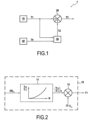
- FIG. 1 represents, in a particular embodiment, a system 1 for estimating a vein temperature of a turbojet of an aircraft (not shown in the figure), in accordance with the invention.
- the estimated vein temperature can be used in particular for regulating and controlling the turbojet engine.
- all or part of the estimation system 1 is coupled or integrated with the full authority regulation device of the aircraft powered by the turbojet engine, also known as FADEC (Full Authority Digital Engine Control).
- FADEC Full Authority Digital Engine Control
- vein temperature estimated using the method according to the invention can be envisaged.
- the estimation system 1 comprises a digital modeling module 10, used to model the vein temperature T 25 .
- the signal T1 delivered by the digital modeling module 10 is then sent to a correction module 20, adapted to add an error signal T2 to the modeled signal T1.
- the T3 signal obtained after correction represents an estimate of the vein temperature T 25 in the turbojet, intended here to be used for the control and regulation of the turbojet.
- the error signal T2, added by the correction module 20 to the modeled signal T1 is evaluated by a calculation module 30 from, on the one hand, the modeled signal T1, and on the other hand, a measurement signal T4 of the vein temperature T25 , delivered by a temperature sensor 40 located in the turbojet.
- a temperature sensor 40 located in the turbojet.
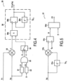
- This estimate is calculated by the entity 11 using a predetermined curve representing the evolution of the adiabatic temperature ratio T 25 /T 12 as a function of the rotation speed N of the fan.
- a curve representing the evolution of the adiabatic temperature ratio T 25 /T 12 as a function of the rotation speed N of the fan.
- the measurement (T 12 ) m of the temperature T 12 and the measurement (N) m of the fan rotation speed are obtained using sensors located in the turbojet engine known per se, and which will not be detailed further here.
- vein temperature T 25 can be used.
- a more elaborate and more accurate numerical model of the vein temperature T 25 can be used. Such a model is described in particular in the document US 5,080,496 .
- the calculation module 30 updates the error signal T2 from the modeled signal T1 and the measurement signal T4, when predetermined conditions relating to thermal stability and to at least one operating phase of the turbojet engine are verified.
- the last updated value of the error signal T2 is used by the correction module 20 to correct the modeled signal T1 (step E13).
- T 2 nTe T 2 n ⁇ 1 You .
- the last updated value of the error signal T2 (step E20), denoted V2f, is stored in a non-volatile memory of the FADEC (not shown in the figure) before the turbojet engine is stopped. figure 1 ).
- a non-volatile memory of the FADEC not shown in the figure
- Such memory is known in itself and will not be detailed further here.
- a thermal stability condition is verified if the vein temperature considered, namely here the temperature T 25 , is stable over a predetermined period of time, in other words, if it does not vary or varies little over this period (within the limits of a predefined threshold value).
- the value of D[ nTe ] obtained at the output of the divider element 31c is then compared to a predefined threshold value s , by a comparator 31d of the verification module 31.
- the threshold value s represents the value of the derivative of the temperature from which the temperature is considered to be stable, that is to say, from which the turbojet is considered to be in a phase of thermal stability.
- the second verification module 32 verifies whether the turbojet is in a particular predefined operating phase, such as for example in a “start” or “full throttle” phase.
- the error signal T2 to be considered to correct the modeled signal T1 is not necessarily the same depending on the operating phase in which the turbojet is located.
- the second verification module 32 checks whether the current operating phase of the turbojet engine, denoted ⁇ , identified by the FADEC according to means known per se, and transmitted to the verification module 32, is equal to phase P1 or to phase P2. If applicable, the verification module 32 delivers a signal C2 equal to 1. If the current operating phase ⁇ is distinct from P1 and P2, then the verification module 32 delivers a signal C2 equal to 0.
- the second verification module 32 verifies whether the current operating phase ⁇ of the turbojet engine transmitted by the FADEC to the second verification module 32 is equal to the phase P1. If applicable, the verification module 32 delivers a signal C2 equal to 1. If the current operating phase ⁇ is distinct from P1, then the verification module 32 delivers a signal C2 equal to 0.
- An AND logic gate 33 whose inputs are the signals C1 and C2, then makes it possible to check whether the two conditions relating respectively to thermal stability and to at least one operating phase of the turbojet are respected.
- the output C of the logic gate 33 is equal to 1 if C1 and C2 are identical and equal to 1 (i.e. if the two aforementioned conditions are respected), and to 0 otherwise.
- the value V2f stored in the non-volatile memory of the FADEC during a previous operation of the turbojet engine is used as the initial value T2 0 .
- the initial value T2 0 can be taken equal to 0.
Landscapes
- Physics & Mathematics (AREA)
- General Physics & Mathematics (AREA)
- Combined Controls Of Internal Combustion Engines (AREA)
- Measuring Volume Flow (AREA)
- Testing Or Calibration Of Command Recording Devices (AREA)
- Control Of Turbines (AREA)
- Testing Of Engines (AREA)
- Investigating Or Analyzing Materials Using Thermal Means (AREA)
- Feedback Control In General (AREA)
Description
L'invention se rapporte au domaine général de l'aéronautique.The invention relates to the general field of aeronautics.
Elle concerne plus particulièrement l'estimation de paramètres, tels que par exemple la température d'un fluide, dans un turboréacteur d'un aéronef.It concerns more particularly the estimation of parameters, such as for example the temperature of a fluid, in a turbojet of an aircraft.
L'invention a une application privilégiée mais non limitative dans le domaine des systèmes de régulation et de pilotage de turboréacteurs.The invention has a preferred but non-limiting application in the field of turbojet regulation and control systems.
En effet, de façon connue, il est nécessaire, pour réguler et adapter le pilotage d'un turboréacteur aux diverses contraintes d'un vol, d'estimer la température de différents flux gazeux traversant le turboréacteur (on parle de températures de veines). A cette fin, on utilise des capteurs de température tels des sondes ou des thermocouples, positionnés à différents endroits des veines d'écoulement des flux gazeux et adaptés à mesurer la température de ces flux gazeux.Indeed, as is known, it is necessary, in order to regulate and adapt the piloting of a turbojet engine to the various constraints of a flight, to estimate the temperature of different gas flows passing through the turbojet engine (we speak of vein temperatures). To this end, temperature sensors such as probes or thermocouples are used, positioned at different locations in the gas flow veins and adapted to measure the temperature of these gas flows.
Ces capteurs de température souffrent généralement, lors d'une mesure, d'une certaine inertie, propre à chaque capteur, et qui dépend notamment de la masse ou de la taille de ce capteur. Cette inertie se traduit par un décalage temporel entre le moment où la mesure est réalisée par le capteur et le moment où celui-ci délivre un signal en réponse à cette mesure. On parle « d'effet de trainage » de la mesure. Un tel effet peut provoquer des disfonctionnements du turboréacteur du fait d'une mauvaise adaptation de celui-ci, et ce notamment lors de variations rapides des températures des flux gazeux.These temperature sensors generally suffer, during a measurement, from a certain inertia, specific to each sensor, and which depends in particular on the mass or size of this sensor. This inertia results in a time lag between the moment when the measurement is carried out by the sensor and the moment when it delivers a signal in response to this measurement. This is called the "dragging effect" of the measurement. Such an effect can cause malfunctions of the turbojet due to poor adaptation of the latter, particularly during rapid variations in the temperatures of the gas flows.
Afin d'éviter un tel disfonctionnement, on peut envisager l'utilisation de capteurs présentant une inertie très faible. Toutefois de tels capteurs sont très coûteux.To avoid such a malfunction, one can consider using sensors with very low inertia. However, such sensors are very expensive.
Aussi, pour pallier cet inconvénient, il existe des techniques permettant de corriger les signaux de mesure délivrés par un capteur de température, en compensant l'effet de trainage induit par l'inertie de ce capteur. Une telle technique est par exemple décrite dans le document
De façon générale, ces techniques s'appuient sur une modélisation numérique de l'inertie du capteur à l'aide d'un filtre paramétré par une estimation de la constante de temps de ce capteur. De façon connue en soi, la constante de temps d'un capteur de mesure caractérise son temps de réponse, c'est-à-dire son inertie.In general, these techniques are based on a numerical modeling of the inertia of the sensor using a filter parameterized by an estimate of the time constant of this sensor. In a manner known per se, the time constant of a measurement sensor characterizes its response time, i.e. its inertia.
Pour estimer la constante de temps d'un capteur de température, les techniques de l'art antérieur utilisent des abaques figés, dépendant d'un ou de plusieurs paramètres, comme par exemple le débit d'écoulement du fluide dans lequel se trouve le capteur. Ces abaques indiquent des valeurs moyennes de constantes de temps pour des gabarits de temps de réponse et des conditions prédéterminés. Autrement dit, ils ne tiennent pas réellement compte de la dispersion de l'inertie d'un capteur de température par rapport à un autre.To estimate the time constant of a temperature sensor, prior art techniques use fixed charts, dependent on one or more parameters, such as the flow rate of the fluid in which the sensor is located. These charts indicate average values of time constants for predetermined response time templates and conditions. In other words, they do not really take into account the dispersion of the inertia of one temperature sensor relative to another.
Or, les technologies de fabrication actuelles ne permettent pas de fabriquer à moindre coût, des capteurs de température pour le pilotage des turboréacteurs qui respectent un gabarit de temps de réponse peu dispersé. Par conséquent, il est difficile d'avoir des abaques adaptés aux différents capteurs de température considérés. Et de nombreux problèmes ont été mis en évidence lorsque les constantes de temps des capteurs embarqués sur un turboréacteur sont éloignées des valeurs données par ces abaques.However, current manufacturing technologies do not allow for the low-cost manufacture of temperature sensors for controlling turbojets that comply with a relatively low-dispersion response time template. Consequently, it is difficult to have charts adapted to the different temperature sensors considered. And many problems have been highlighted when the time constants of the sensors embedded in a turbojet are far from the values given by these charts.
Une solution pourrait être de tester chaque capteur de température, par exemple en soufflerie, en vue de déterminer sa constante de temps dans des conditions prédéfinies et d'extrapoler les abaques en fonction de la constante ainsi déterminée. Cependant, un tel test est particulièrement coûteux et représente environ un tiers du prix du capteur de température. Par conséquent, il ne peut être mis en oeuvre pour chaque capteur de température, ce qui signifie qu'un capteur de température en dehors d'un gabarit d'acceptation pour lequel un abaque est disponible, pourrait ne pas être détecté.One solution could be to test each temperature sensor, for example in a wind tunnel, to determine its time constant under predefined conditions and to extrapolate the charts based on the constant thus determined. However, such a test is particularly expensive and represents about one third of the price of the temperature sensor. Therefore, it cannot be implemented for each temperature sensor, which means that a temperature sensor outside an acceptance template for which a chart is available, might not be detected.
En outre, de tels tests sont souvent réalisés pour des débits d'écoulement de fluides limités par les capacités de la soufflerie, et ne permettent pas généralement de couvrir la plage de débits utiles pour les applications d'un turboréacteur. Or, l'extrapolation des abaques de façon à couvrir toute la plage des débits utiles introduit des imprécisions dans la chaîne d'acquisition du capteur de température.Furthermore, such tests are often performed for fluid flow rates limited by the wind tunnel capabilities, and do not generally cover the range of flow rates useful for turbojet applications. However, extrapolating the charts to cover the entire range of useful flow rates introduces inaccuracies into the temperature sensor acquisition chain.
Par ailleurs, comme mentionné précédemment, la constante de temps d'un capteur de température dépend de paramètres tels le débit d'écoulement du fluide dans lequel se trouve le capteur. Cela signifie que pour estimer la constante de temps d'un capteur de température, il est nécessaire, au préalable, d'estimer ce débit d'écoulement de fluide. Par conséquent, la mise en oeuvre d'estimateurs complémentaires sur le turboréacteur est nécessaire, ce qui rend d'autant plus complexe la correction des mesures.Furthermore, as mentioned above, the time constant of a temperature sensor depends on parameters such as the flow rate of the fluid in which the sensor is located. This means that to estimate the time constant of a temperature sensor, it is necessary to first estimate this fluid flow rate. Consequently, the implementation of additional estimators on the turbojet is necessary, which makes the correction of the measurements all the more complex.
Par conséquent, il existe un besoin d'un procédé d'estimation d'une température de veine d'un turboréacteur, qui soit simple et peu coûteux, et délivre une estimation précise de cette température, afin de pouvoir être utilisée notamment pour la régulation et le pilotage de turboréacteurs.Therefore, there is a need for a method for estimating a jet engine temperature, which is simple and inexpensive, and provides a precise estimation of this temperature, so that it can be used in particular for regulating and controlling jet engines.
La présente invention répond à ce besoin en proposant un procédé d'estimation d'une température de veine dans un turboréacteur, un système d'estimation d'une température de veine dans un turboréacteur, et un turboréacteur, conformes aux revendications indépendantes. Le procédé comprend :
- une étape de modélisation numérique de la température de veine à l'aide d'un signal modélisé ;
- une étape de correction de ce signal modélisé à l'aide d'un signal d'erreur, le signal obtenu après correction représentant une estimation de la température de veine ;
- a step of numerical modeling of the vein temperature using a modeled signal;
- a step of correcting this modeled signal using an error signal, the signal obtained after correction representing an estimate of the vein temperature;
Ainsi, au lieu d'estimer une température de veine d'un turboréacteur au moyen d'une mesure issue d'un capteur corrigée à l'aide d'une estimation de la constante de temps de ce capteur comme dans l'art antérieur, l'invention propose d'estimer cette température de veine en utilisant un modèle numérique corrigé à l'aide d'un signal d'erreur évalué lors d'une phase de stabilité thermique du turboréacteur, dans des conditions prédéterminées relatives à au moins une phase de fonctionnement de ce turboréacteur.Thus, instead of estimating a vein temperature of a turbojet engine by means of a measurement from a sensor corrected using an estimation of the time constant of this sensor as in the prior art, the invention proposes to estimate this vein temperature by using a digital model corrected using an error signal evaluated during a thermal stability phase of the turbojet engine, under predetermined conditions relating to at least one operating phase of this turbojet engine.
De cette sorte, on évite des calculs coûteux d'estimation de la constante de temps du capteur, ce qui permet d'alléger la charge du calculateur du turboréacteur, c'est-à-dire typiquement du FADEC (Full Authority Digital Engine Control).In this way, costly calculations for estimating the sensor time constant are avoided, which helps to reduce the load on the turbojet computer, i.e. typically the FADEC (Full Authority Digital Engine Control).
L'invention permet d'obtenir une estimation de bonne qualité de la température de veine considérée à faible coût. Le recours à des capteurs de température coûteux présentant une très faible inertie est ainsi évité.The invention makes it possible to obtain a good quality estimate of the temperature of the vein considered at low cost. The use of expensive temperature sensors with very low inertia is thus avoided.
L'invention s'appuie en effet sur des modèles numériques de température de veine existants et connus en soi. De tels modèles numériques offrent généralement une bonne représentation de l'évolution de la température de veine dans un turboréacteur (c'est-à-dire de sa dynamique), mais ne sont pas précis quant aux valeurs « absolues » prises par cette température, i.e., ils présentent une erreur statique par rapport à la température de veine réelle du turboréacteur. L'invention propose de corriger cette erreur statique afin d'obtenir une estimation précise de la température de veine considérée.The invention is based on existing and known numerical models of vein temperature. Such numerical models generally offer a good representation of the evolution of the vein temperature in a turbojet engine (i.e. its dynamics), but are not precise as to the "absolute" values taken by this temperature, i.e., they have a static error relative to the actual vein temperature of the turbojet engine. The invention proposes to correct this static error in order to obtain a precise estimate of the vein temperature considered.
A cette fin, elle utilise un signal d'erreur mis à jour lors de phases de stabilité thermique à l'aide d'un signal de mesure issu d'un capteur de température. La détection qu'une condition de stabilité thermique est vérifiée peut être aisément mise en oeuvre, par exemple en comparant la dérivée du signal de mesure délivré par le capteur par rapport à un seuil prédéterminé.For this purpose, it uses an error signal updated during thermal stability phases using a measurement signal from a temperature sensor. The detection that a thermal stability condition is verified can be easily implemented, for example by comparing the derivative of the measurement signal delivered by the sensor with respect to a predetermined threshold.
En outre, les exigences de précision et de dynamique du capteur de température utilisé par l'invention sont faibles, le signal de mesure issu du capteur de température n'étant en effet considéré que pour corriger lors d'une phase stabilisée thermiquement, le modèle de température de veine du turboréacteur. On peut donc utiliser des capteurs de température à faible coût, présentant des constantes de temps élevées pourvu que celles-ci soient compatibles avec les phases de stabilité thermique du turboréacteur (autrement dit inférieures à la durée des phases de stabilité thermique du turboréacteur).Furthermore, the accuracy and dynamic requirements of the temperature sensor used by the invention are low, the measurement signal from the temperature sensor being considered only to correct the jet engine flow temperature model during a thermally stabilized phase. It is therefore possible to use low-cost temperature sensors with high time constants provided that these are compatible with the thermal stability phases of the jet engine (in other words, less than the duration of the thermal stability phases of the jet engine).
Par ailleurs, l'invention prend avantageusement en compte les phases de fonctionnement du turboréacteur. Elle offre ainsi la possibilité d'estimer un signal d'erreur distinct en fonction de la phase de fonctionnement dans laquelle se trouve le turboréacteur. L'erreur statique des modèles numériques existant au cours d'une phase de démarrage peut en effet être différente d'une erreur statique lors d'une phase de fonctionnement « plein gaz ».Furthermore, the invention advantageously takes into account the operating phases of the turbojet engine. It thus offers the possibility of estimating a distinct error signal depending on the operating phase in which the turbojet engine is located. The static error of the numerical models existing during a start-up phase may in fact be different from a static error during a “full throttle” operating phase.
Dans un mode particulier de réalisation de l'invention, on met à jour le signal d'erreur à l'aide d'un algorithme adaptatif.In a particular embodiment of the invention, the error signal is updated using an adaptive algorithm.
Le signal d'erreur peut notamment être mis à jour à partir du signal obtenu par soustraction du signal modélisé au signal de mesure.The error signal can in particular be updated from the signal obtained by subtracting the modeled signal from the measurement signal.
De cette sorte, on obtient une bonne estimation de l'erreur statique que présente le signal modélisé.In this way, a good estimate of the static error presented by the modeled signal is obtained.
En effet, lors d'une phase de stabilité thermique, le capteur de température, même s'il souffre d'une inertie importante, est capable de fournir une bonne représentation « absolue » de la température de veine du turboréacteur qu'il mesure. Cette représentation soustraite à la valeur du signal modélisé sur la phase de stabilité thermique permet donc d'estimer avec précision l'erreur statique que présente le signal modélisé.Indeed, during a thermal stability phase, the temperature sensor, even if it suffers from significant inertia, is able to provide a good "absolute" representation of the jet engine temperature that it measures. This representation subtracted from the value of the modeled signal on the thermal stability phase therefore makes it possible to accurately estimate the static error presented by the modeled signal.
La mise à jour du signal d'erreur peut être réalisée à l'aide d'un filtre de type correcteur intégral paramétré par un gain prédéterminé, de préférence non unitaire.The update of the error signal can be carried out using an integral corrector type filter parameterized by a predetermined gain, preferably non-unitary.
Un tel filtre est connu en soi, et présente de bonnes performances pour la correction du signal modélisé.Such a filter is known per se, and shows good performance for correcting the modeled signal.
En variante, d'autres filtres peuvent être utilisés, tels que par exemple des filtres d'ordres supérieurs. Le choix de l'ordre du filtre considéré pour la mise à jour du signal d'erreur peut résulter d'un compromis entre la précision obtenue et la complexité des calculs mis en oeuvre.Alternatively, other filters may be used, such as for example higher order filters. The choice of the order of the filter considered for updating the error signal may result from a compromise between the precision obtained and the complexity of the calculations implemented.
Dans une variante de réalisation, le procédé d'estimation comprend en outre une étape de mémorisation, dans une mémoire non volatile, du dernier signal d'erreur mis à jour avant l'arrêt du turboréacteur.In an alternative embodiment, the estimation method further comprises a step of storing, in a non-volatile memory, the last error signal updated before the turbojet engine is stopped.
Cette valeur peut notamment, de façon avantageuse, être utilisée pour initialiser l'algorithme adaptatif de mise à jour du signal d'erreur, plutôt que d'utiliser une valeur initiale prédéterminée (ex. nulle). Celle-ci peut permettre d'accélérer la convergence de l'algorithme adaptatif ou être utilisée comme valeur par défaut du signal d'erreur en attendant de détecter une phase de stabilité thermique, suite au redémarrage du turboréacteur.This value can in particular, advantageously, be used to initialize the adaptive algorithm for updating the error signal, rather than using a predetermined initial value (e.g. zero). This can make it possible to accelerate the convergence of the adaptive algorithm or be used as a default value of the error signal while waiting to detect a thermal stability phase, following the restart of the turbojet.
Corrélativement, l'invention vise également un système d'estimation d'une température de veine d'un turboréacteur comprenant :
- des moyens de modélisation numérique de cette température de veine à l'aide d'un signal modélisé ;
- des moyens de correction de ce signal modélisé à l'aide d'un signal d'erreur, le signal obtenu après correction représentant une estimation de la température de veine ;
- des moyens de mise à jour du signal d'erreur activés lorsque des conditions prédéterminées relatives à au moins une phase de fonctionnement du turboréacteur et à une stabilité thermique sont vérifiées, à partir du signal modélisé et d'un signal de mesure de la température de veine délivré par un capteur de température.
- means of digital modeling of this vein temperature using a modeled signal;
- means for correcting this modeled signal using an error signal, the signal obtained after correction representing an estimate of the vein temperature;
- error signal updating means activated when predetermined conditions relating to at least one operating phase of the turbojet and thermal stability are verified, from the modeled signal and a vein temperature measurement signal delivered by a temperature sensor.
L'invention vise également un turboréacteur comportant au moins un système d'estimation d'une température de veine de ce turboréacteur tel que décrit précédemment.The invention also relates to a turbojet engine comprising at least one system for estimating a vein temperature of this turbojet engine as described previously.
D'autres caractéristiques et avantages de la présente invention ressortiront de la description faite ci-dessous, en référence aux dessins annexés qui en illustrent un exemple de réalisation dépourvu de tout caractère limitatif. Sur les figures :
- la
figure 1 représente, de façon schématique, un système d'estimation d'une température de veine d'un turboréacteur conforme à l'invention, dans un mode particulier de réalisation ; - la
figure 2 représente, sous forme schématique, un exemple de module de modélisation numérique pouvant être utilisé dans le système d'estimation représenté sur lafigure 1 pour modéliser la température de veine ; - la
figure 3 représente, sous la forme d'un organigramme, les principales étapes mises en oeuvre pour évaluer le signal d'erreur utilisé pour corriger le signal modélisé au cours du procédé d'estimation selon l'invention, dans un mode particulier de réalisation et lorsqu'il est mis en oeuvre par le système représenté sur lafigure 1 ; - la
figure 4 représente, sous forme schématique, un exemple de moyens pouvant être mis en oeuvre pour évaluer le signal d'erreur utilisé pour corriger le signal modélisé au cours du procédé d'estimation selon l'invention, dans un mode particulier de réalisation et lorsqu'il est mis en oeuvre par le système représenté sur lafigure 1 ; et - la
figure 5 représente, sous forme schématique, un exemple de moyens de détection d'une condition de stabilité thermique pouvant être mis en oeuvre au cours du procédé d'estimation selon l'invention.
- there
figure 1 schematically represents a system for estimating a vein temperature of a turbojet according to the invention, in a particular embodiment; - there
figure 2 represents, in schematic form, an example of a digital modeling module that can be used in the estimation system shown in thefigure 1 to model the vein temperature; - there
figure 3 represents, in the form of a flowchart, the main steps implemented to evaluate the error signal used to correct the modeled signal during the estimation method according to the invention, in a particular embodiment and when it is implemented by the system represented in thefigure 1 ; - there
figure 4 represents, in schematic form, an example of means which can be implemented to evaluate the error signal used to correct the modeled signal during the estimation method according to the invention, in a particular embodiment and when it is implemented by the system represented in thefigure 1 ; And - there
figure 5 represents, in schematic form, an example of means for detecting a thermal stability condition which can be implemented during the estimation method according to the invention.
La
La température de veine estimée peut être utilisée notamment pour la régulation et le pilotage du turboréacteur. Ainsi, dans le mode de réalisation décrit ici, tout ou partie du système d'estimation 1 est couplé ou intégré au dispositif de régulation pleine autorité de l'avion propulsé par le turboréacteur, également connu sous le nom de FADEC (Full Authority Digital Engine Control).The estimated vein temperature can be used in particular for regulating and controlling the turbojet engine. Thus, in the embodiment described here, all or part of the
Toutefois, bien entendu, d'autres utilisations de la température de veine estimée à l'aide du procédé selon l'invention peuvent être envisagées.However, of course, other uses of the vein temperature estimated using the method according to the invention can be envisaged.
Dans l'exemple décrit ici, on envisage l'estimation de la température de veine T25 en entrée du compresseur haute-pression du turboréacteur.In the example described here, we consider the estimation of the vein temperature T 25 at the inlet of the high-pressure compressor of the turbojet.
Conformément à l'invention, le système d'estimation 1 comprend un module de modélisation numérique 10, utilisé pour modéliser la température de veine T25.According to the invention, the
Le signal T1 délivré par le module de modélisation numérique 10 est ensuite envoyé vers un module de correction 20, adapté à ajouter au signal modélisé T1 un signal d'erreur T2.The signal T1 delivered by the
Le signal T3 obtenu après correction représente une estimation de la température de veine T25 dans le turboréacteur, destinée ici à être utilisée pour le pilotage et la régulation du turboréacteur.The T3 signal obtained after correction represents an estimate of the vein temperature T 25 in the turbojet, intended here to be used for the control and regulation of the turbojet.
Le signal d'erreur T2, ajouté par le module de correction 20 au signal modélisé T1, est évalué par un module de calcul 30 à partir d'une part, du signal modélisé T1, et d'autre part, d'un signal de mesure T4 de la température de veine T25, délivré par un capteur de température 40 situé dans le turboréacteur. La structure et le fonctionnement d'un tel capteur de température sont connus en soi et ne seront pas décrits plus en détails ici.The error signal T2, added by the
Nous allons maintenant décrire, en référence à la
Selon l'exemple représenté sur la
Cette estimation est calculée par l'entité 11 à l'aide d'une courbe prédéterminée représentant l'évolution du rapport adiabatique de températures T25/T12 en fonction de la vitesse de rotation N de la soufflante. Une telle courbe est connue de l'homme du métier et ne sera pas décrite plus en détails ici.This estimate is calculated by the
L'estimation du rapport T25/T12 est ensuite envoyée vers un circuit multiplicateur 12, adapté à multiplier ce rapport par une mesure de la température T12, notée (T12)m. On obtient ainsi, en sortie du circuit multiplicateur 12, le signal T1 modélisant la température de veine T25.The estimate of the ratio T 25 /T 12 is then sent to a
La mesure (T12)m de la température T12 et la mesure (N)m de la vitesse de rotation de la soufflante sont obtenues à l'aide de capteurs situés dans le turboréacteur connus en soi, et qui ne seront pas détaillés davantage ici.The measurement (T 12 ) m of the temperature T 12 and the measurement (N) m of the fan rotation speed are obtained using sensors located in the turbojet engine known per se, and which will not be detailed further here.
En variante, un modèle numérique plus élaboré et plus précis de la température de veine T25 peut être utilisé. Un tel modèle est décrit notamment dans le document
On notera, que dans l'exemple décrit ici, on considère la correction d'un signal modélisé représentatif de la température T25. Toutefois, l'invention s'applique à d'autres températures de veine dans le turboréacteur, à condition de disposer d'un modèle d'évolution de ces températures.It should be noted that in the example described here, we consider the correction of a modeled signal representative of the temperature T 25 . However, the invention applies to other vein temperatures in the turbojet, provided that a model of the evolution of these temperatures is available.
Nous allons maintenant décrire, en référence à la
Dans la suite de la description, on considère des signaux et des paramètres échantillonnés à une période d'échantillonnage Te. On notera que l'invention peut également être mise en oeuvre avec des signaux et des paramètres continus.In the remainder of the description, signals and parameters sampled at a sampling period Te are considered. It will be noted that the invention can also be implemented with continuous signals and parameters.
Conformément à l'invention, durant le fonctionnement du turboréacteur (E10), le module de calcul 30 met à jour le signal d'erreur T2 à partir du signal modélisé T1 et du signal de mesure T4, lorsque des conditions prédéterminées relatives à une stabilité thermique et à au moins une phase de fonctionnement du turboréacteur sont vérifiées.According to the invention, during operation of the turbojet engine (E10), the
De façon plus précise, dans le mode de réalisation envisagé ici, lorsque ces conditions sont vérifiées (étape E11), le signal d'erreur T2 est évalué à un instant donné t=nTe (n étant un entier, Te désignant la période d'échantillonnage), à l'aide d'un filtre adaptatif de type correcteur intégral selon l'équation suivante (étape E12) : ![]()
![]()
- K est un nombre réel prédéterminé désignant le gain du filtre correcteur intégral ;
- T2[nTe], ε[nTe], T4[nTe] et T1[nTe] désignent respectivement le signal d'erreur T2, le signal ε, le signal de mesure T4 et le signal modélisé T1 échantillonnés à l'instant nTe.
- K is a predetermined real number designating the gain of the integral correction filter;
- T2[ nTe ], ε [ nTe ], T4[ nTe ] and T1[ nTe ] denote respectively the error signal T2, the signal ε, the measurement signal T4 and the modeled signal T1 sampled at time nTe.
En variante, des filtres d'ordres supérieurs peuvent être utilisés pour l'évaluation du signal T2.Alternatively, higher order filters can be used for T2 signal evaluation.
Lorsque l'on détermine que l'une et/ou l'autre des conditions précitées n'est ou ne sont pas vérifiée(s) (étape E11), la dernière valeur mise à jour du signal d'erreur T2 est utilisée par le module de correction 20 pour corriger le signal modélisé T1 (étape E13). Autrement dit, de façon équivalente : ![]()
![]()
On notera que dans le mode de réalisation décrit ici, on mémorise, avant l'arrêt du turboréacteur, la dernière valeur mise à jour du signal d'erreur T2 (étape E20), notée V2f, dans une mémoire non volatile du FADEC (non représentée sur la
La valeur V2f ainsi mémorisée pourra être utilisée de façon avantageuse lors d'un prochain fonctionnement du turboréacteur, pour initialiser le filtre correcteur intégral.The V2f value thus stored can be used advantageously during a future operation of the turbojet, to initialize the integral corrective filter.
Nous allons maintenant décrire, en référence à la
Au sens de l'invention, on considère qu'une condition de stabilité thermique est vérifiée si la température de veine considérée, à savoir ici la température T25, est stable sur une période de temps prédéterminée, autrement dit, si elle ne varie pas ou varie peu sur cette période (dans les limites d'une valeur de seuil prédéfinie).For the purposes of the invention, it is considered that a thermal stability condition is verified if the vein temperature considered, namely here the temperature T 25 , is stable over a predetermined period of time, in other words, if it does not vary or varies little over this period (within the limits of a predefined threshold value).
En outre, au sens de l'invention, on considère qu'une condition relative à au moins une phase de fonctionnement du turboréacteur est vérifiée si le turboréacteur se trouve dans l'une au moins de ces phases de fonctionnement.Furthermore, within the meaning of the invention, it is considered that a condition relating to at least one operating phase of the turbojet engine is verified if the turbojet engine is in at least one of these operating phases.
Dans le mode de réalisation décrit ici, pour vérifier si les deux conditions précitées sont respectées, on procède séparément à l'examen de ces deux conditions à l'aide de deux modules distincts, à savoir :
- la condition de stabilité thermique est examinée par un premier module de vérification 31 ; et
- la condition relative à au moins une phase de fonctionnement du turboréacteur est examinée par un second module de vérification 32.
- the thermal stability condition is examined by a
first verification module 31; and - the condition relating to at least one operating phase of the turbojet is examined by a
second verification module 32.
Un exemple de module de vérification 31 adapté à examiner si une condition de stabilité thermique est respectée est représenté sur la
Pour vérifier si une condition de stabilité thermique est respectée, le module de vérification 31 calcule un signal D représentatif de la dérivée du signal de mesure T4 délivré par le capteur de température 40 à l'instant t=nTe. To check whether a thermal stability condition is met, the
Le signal D est évalué ici à l'aide d'un filtre d'ordre 1 selon l'équation suivante : ![]()
![]()
A cette fin, de façon connue, le module de vérification 31 comprend :
- une cellule de retard 31a délivrant la valeur du signal de mesure T4 à l'instant précédent (n-1)Te ;
- un élément soustracteur 31b permettant de soustraire le signal de mesure retardé T4[(n-1)Te] au signal de mesure T4[nTe] ; et
- un élément diviseur 31c adapté à diviser la sortie de l'élément 31b par la période d'échantillonnage Te.
- a
delay cell 31a delivering the value of the measurement signal T4 at the previous instant (n-1)Te ; - a subtracting
element 31b for subtracting the delayed measurement signal T4[ (n-1)Te ] from the measurement signal T4 [ nTe ]; and - a dividing
element 31c adapted to divide the output ofelement 31b by the sampling period Te .
En variante, la dérivée D du signal T4 à l'instant t=nTe peut être calculée à l'aide d'un filtre d'ordre supérieur.Alternatively, the derivative D of the signal T4 at time t= nTe can be calculated using a higher order filter.
La valeur de D[nTe] obtenue en sortie de l'élément diviseur 31c est ensuite comparée à une valeur de seuil s prédéfinie, par un comparateur 31d du module de vérification 31. La valeur de seuil s représente la valeur de la dérivée de la température à partir de laquelle on considère que la température est stable, c'est-à-dire, à partir de laquelle on considère que le turboréacteur se trouve dans une phase de stabilité thermique.The value of D[ nTe ] obtained at the output of the
Le comparateur 31d est adapté à délivrer ici :
- un signal C1 égal à 1, si la valeur de D[nTe] est inférieure ou égale à la valeur de seuil s ; et
- un signal C1 égal à 0, si la valeur de D[nTe] est supérieure à la valeur de seuil s.
- a signal C1 equal to 1, if the value of D[n Te ] is less than or equal to the threshold value s ; and
- a signal C1 equal to 0, if the value of D[ nTe ] is greater than the threshold value s .
Le second module de vérification 32 vérifie, quant à lui, si le turboréacteur se trouve dans une phase de fonctionnement particulière prédéfinie, comme par exemple dans une phase « démarrage » ou « plein gaz ».The
En effet, le signal d'erreur T2 à considérer pour corriger le signal modélisé T1 n'est pas nécessairement le même selon la phase de fonctionnement dans laquelle se trouve le turboréacteur.In fact, the error signal T2 to be considered to correct the modeled signal T1 is not necessarily the same depending on the operating phase in which the turbojet is located.
Ainsi, s'il existe une différence entre les corrections à apporter au signal modélisé durant diverses phases de fonctionnement prédéfinies du turboréacteur, tel que par exemple durant une phase P1 de démarrage et une phase P2 de fonctionnement « plein gaz » du turboréacteur, le signal de correction T2 sera mis à jour pendant chacune de ces deux phases. Dans ce cas, le second module de vérification 32 vérifie si la phase de fonctionnement en cours du turboréacteur, notée φ, identifiée par le FADEC selon des moyens connus en soi, et transmise au module de vérification 32, est égale à la phase P1 ou à la phase P2. Le cas échéant, le module de vérification 32 délivre un signal C2 égal à 1. Si la phase de fonctionnement φ en cours est distincte de P1 et de P2, alors le module de vérification 32 délivre un signal C2 égal à 0.Thus, if there is a difference between the corrections to be made to the modeled signal during various predefined operating phases of the turbojet engine, such as for example during a start-up phase P1 and a “full throttle” operating phase P2 of the turbojet engine, the correction signal T2 will be updated during each of these two phases. In this case, the
Au contraire, si on détermine, par exemple au cours de tests de fonctionnement préalables réalisés sur le turboréacteur ou sur un turboréacteur de mêmes caractéristiques, qu'une correction similaire doit être apportée au cours des phases P1 et P2 du turboréacteur, alors il est possible de ne mettre à jour le signal de correction T2 que pendant l'une de ces phases, par exemple pendant la phase P1.On the contrary, if it is determined, for example during preliminary operating tests carried out on the turbojet engine or on a turbojet engine with the same characteristics, that a similar correction must be made during phases P1 and P2 of the turbojet engine, then it is possible to update the correction signal T2 only during one of these phases, for example during phase P1.
Ainsi, dans ce cas, le second module de vérification 32 vérifie si la phase de fonctionnement φ en cours du turboréacteur transmise par le FADEC au second module de vérification 32, est égale à la phase P1. Le cas échéant, le module de vérification 32 délivre un signal C2 égal à 1. Si la phase de fonctionnement φ en cours est distincte de P1, alors le module de vérification 32 délivre un signal C2 égal à 0.Thus, in this case, the
Dans l'exemple donné ici on considère deux phases de fonctionnement P1 et P2 du turboréacteur. Bien entendu d'autres phases pourraient être considérées.In the example given here we consider two operating phases P1 and P2 of the turbojet. Of course other phases could be considered.
Une porte logique ET 33, dont les entrées sont les signaux C1 et C2, permet alors de vérifier si les deux conditions relatives respectivement à une stabilité thermique et à au moins une phase de fonctionnement du turboréacteur sont respectées. La sortie C de la porte logique 33 est égale à 1 si C1 et C2 sont identiques et égales à 1 (i.e. si les deux conditions précitées sont respectées), et à 0 sinon.An AND
Le signal C délivré par la porte logique 33 conditionne la sortie d'un module 34 de la façon suivante :
- si C est égal à 1, la sortie du
module 34 est égale au gain réel K du filtre correcteur intégral utilisé pour mettre à jour le signal d'erreur T2 introduit précédemment ; - sinon, la sortie du
module 34 est égale à zéro.
- if C is equal to 1, the output of
module 34 is equal to the real gain K of the integral correction filter used to update the error signal T2 introduced previously; - otherwise, the output of
module 34 is zero.
En parallèle de la vérification des conditions relatives à la stabilité thermique et à au moins une phase de fonctionnement du moteur, un module soustracteur 35 évalue le signal ε[nTe] à l'instant t=nTe, en soustrayant au signal de mesure T4 délivré par le capteur de température 40, le signal modélisé T1 issu du modèle numérique 10, selon l'équation suivante : ![]()
![]()
Le signal ε ainsi que la sortie du module 34 sont ensuite fournis à un filtre 36. Le filtre 36 comprend :
- un élément multiplieur 36a, adapté à multiplier le signal ε[nTe] par la sortie du
module 34. Autrement dit, l'élément multiplieur 36a multiplie le signal ε[nTe] par le gain K si les conditions relatives à une stabilité thermique et à au moins une phase de fonctionnement sont vérifiées, et par zéro sinon ; - une cellule de retard 36c délivrant la valeur T2[(n-1)Te]; et
- un élément additionneur 36b adapté à calculer la valeur T2[nTe] selon l'équation indiquée précédemment.
- a
multiplier element 36a, adapted to multiply the signal ε[ nTe ] by the output of themodule 34. In other words, themultiplier element 36a multiplies the signal ε[ nTe ] by the gain K if the conditions relating to thermal stability and to at least one operating phase are verified, and by zero otherwise; - a 36c delay cell delivering the value T2[ (n-1) Te]; and
- an
adder element 36b adapted to calculate the value T2[ nTe ] according to the equation indicated previously.
On notera, qu'à l'instant t=0 (i.e. pour n=0), on prendra comme valeur initiale du signal d'erreur T2[0] = T20, où T20 est une valeur prédéfinie.Note that at time t = 0 (i.e. for n=0), we will take as the initial value of the error signal T2[0] = T2 0 , where T2 0 is a predefined value.
Dans le mode de réalisation décrit ici, on utilise comme valeur initiale T20, la valeur V2f mémorisée dans la mémoire non volatile du FADEC lors d'un fonctionnement précédent du turboréacteur.In the embodiment described here, the value V2f stored in the non-volatile memory of the FADEC during a previous operation of the turbojet engine is used as the initial value T2 0 .
En variante, la valeur initiale T20 peut être prise égale à 0.Alternatively, the initial value T2 0 can be taken equal to 0.
On notera que, de façon connue en soi, le choix de la valeur initiale T20, de la période d'échantillonnage Te et de la valeur du gain K résulte d'un compromis entre performance et rapidité de convergence de l'algorithme adaptatif mis en oeuvre pour la mise à jour du signal T2.It should be noted that, as is known per se, the choice of the initial value T2 0 , of the sampling period Te and of the value of the gain K results from a compromise between performance and speed of convergence of the adaptive algorithm implemented for updating the signal T2.
Claims (9)
- A method for estimating a stream temperature in a turbojet, the method comprising:- a step for digitally modeling (10) the stream temperature based on of a modeled signal (T1);- a step for correcting (20) this modeled signal using an error signal (T2), the signal obtained after correction (T3) representing an estimate of the stream temperature;and characterized in that the error signal (T2) is updated (E20) when it is detected that predetermined conditions relative to at least one operating phase of the turbojet and temperature stability are verified, from the modeled signal (T1) and a measurement signal (T4) of the stream temperature delivered by a temperature sensor (40), using a filter of order greater than or equal to 1, the updated error signal being obtained at the output of the filter,wherein the estimated stream temperature is intended to be used for the regulation and control of the turbojet, andwherein the temperature stability condition is verified if the stream temperature is stable over a predetermined time period.
- The estimating method according to claim 1, wherein the error signal (T2) is updated based on an adaptive algorithm.
- The estimating method according to claim 2, further comprising a step for storing (E40), in a non-volatile memory, the most recent updated error signal before stopping the turbojet.
- The estimating method according to claim 3, wherein an error signal stored in the non-volatile memory is used to initialize the adaptive algorithm.
- The estimating method according to any one of claims 2 to 4, wherein the error signal (T2) is updated (E20) using a filter of the integral corrector type configured by a predetermined gain (K).
- The estimating method according to any one of claims 2 to 5, wherein the error signal (T2) is updated (E20) from a signal (ε) obtained by subtracting the modeled signal (T1) from the measurement signal (T4).
- The estimating method according to any one of claims 1 to 6, wherein it is detected (E10) that a temperature stability condition is verified by comparing the derivative (D) of the measurement signal (T4) delivered by the sensor (40) relative to a predetermined threshold (s).
- A system (1) for estimating a stream temperature of a turbojet, comprising:- means for digitally modeling (10) this stream temperature using a modeled signal (T1);- means for correcting (20) this modeled signal (T1) using an error signal (T2), the signal (T3) obtained after correction representing an estimate of the stream temperature;
characterized in that the system comprises- means for verifying (31, 32) whether predetermined conditions relative to at least one operating phase of the turbojet and temperature stability are verified; and- means for updating (30) the error signal, activated when the verification means detect that said predetermined conditions are verified, from the modeled signal (T1) and a measurement signal (T4) of the stream temperature delivered by a temperature sensor (40), using a filter of order greater than or equal to 1, the updated error signal being obtained at the output of the filter,the estimated stream temperature being intended to be used for the regulation and control of the turbojet, andthe temperature stability condition being verified if the stream temperature is stable over a predetermined period of time. - A turbojet, characterized in that it comprises at least one system (1) for estimating a stream temperature according to claim 8.
Applications Claiming Priority (2)
| Application Number | Priority Date | Filing Date | Title |
|---|---|---|---|
| FR0858381A FR2939509B1 (en) | 2008-12-09 | 2008-12-09 | METHOD AND SYSTEM FOR ESTIMATING A VEIN TEMPERATURE IN A TURBOKIN. |
| PCT/FR2009/052449 WO2010067011A1 (en) | 2008-12-09 | 2009-12-08 | Method for estimating a jet temperature in a jet engine |
Publications (3)
| Publication Number | Publication Date |
|---|---|
| EP2373965A1 EP2373965A1 (en) | 2011-10-12 |
| EP2373965B1 EP2373965B1 (en) | 2016-06-22 |
| EP2373965B2 true EP2373965B2 (en) | 2024-10-16 |
Family
ID=40908630
Family Applications (1)
| Application Number | Title | Priority Date | Filing Date |
|---|---|---|---|
| EP09801510.0A Active EP2373965B2 (en) | 2008-12-09 | 2009-12-08 | Method for estimating a jet temperature in a jet engine |
Country Status (9)
| Country | Link |
|---|---|
| US (1) | US8682627B2 (en) |
| EP (1) | EP2373965B2 (en) |
| JP (1) | JP5575795B2 (en) |
| CN (1) | CN102246017B (en) |
| BR (1) | BRPI0922329B1 (en) |
| CA (1) | CA2745977C (en) |
| FR (1) | FR2939509B1 (en) |
| RU (1) | RU2507489C2 (en) |
| WO (1) | WO2010067011A1 (en) |
Families Citing this family (3)
| Publication number | Priority date | Publication date | Assignee | Title |
|---|---|---|---|---|
| FR2985057B1 (en) * | 2011-12-23 | 2014-12-12 | Snecma | METHOD AND DEVICE FOR ESTIMATING A THICKNESS OF A CERAMIC THERMAL BARRIER COATING |
| FR3080680B1 (en) * | 2018-04-26 | 2020-05-08 | Safran Aircraft Engines | METHOD AND SYSTEM FOR PROCESSING A MEASUREMENT SIGNAL OF A TEMPERATURE DELIVERED BY A SENSOR |
| US11513031B2 (en) | 2019-10-28 | 2022-11-29 | Aktiebolaget Skf | Conformance test apparatus, sensor system, and processes |
Citations (2)
| Publication number | Priority date | Publication date | Assignee | Title |
|---|---|---|---|---|
| US4215412A (en) † | 1978-07-13 | 1980-07-29 | The Boeing Company | Real time performance monitoring of gas turbine engines |
| US20070073525A1 (en) † | 2005-09-27 | 2007-03-29 | General Electric Company | Method and system for gas turbine engine simulation using adaptive Kalman filter |
Family Cites Families (14)
| Publication number | Priority date | Publication date | Assignee | Title |
|---|---|---|---|---|
| GB1316498A (en) * | 1970-05-26 | 1973-05-09 | Ultra Electronics Ltd | Temperature compensation arrangements |
| US4594849A (en) * | 1984-12-20 | 1986-06-17 | United Technologies Corporation | Apparatus for synthesizing control parameters |
| US5080496A (en) * | 1990-06-25 | 1992-01-14 | General Electric Company | Method and apparatus for compensated temperature prediction |
| US6270252B1 (en) * | 1999-05-18 | 2001-08-07 | Alaris Medical Systems, Inc. | Predictive temperature measurement system |
| US6564109B1 (en) * | 1999-11-26 | 2003-05-13 | General Electric Company | Methods and systems for compensation of measurement error |
| US7071649B2 (en) * | 2001-08-17 | 2006-07-04 | Delphi Technologies, Inc. | Active temperature estimation for electric machines |
| US7200538B2 (en) * | 2003-01-15 | 2007-04-03 | General Electric Company | Methods and apparatus for modeling gas turbine engines |
| JP4434815B2 (en) * | 2004-03-31 | 2010-03-17 | 本田技研工業株式会社 | Control device for gas turbine engine |
| SE0403229D0 (en) * | 2004-12-30 | 2004-12-30 | Abb Ab | A method and a system for adaptive compensation of the temperature operation of a sensor |
| US20060212281A1 (en) * | 2005-03-21 | 2006-09-21 | Mathews Harry Kirk Jr | System and method for system-specific analysis of turbomachinery |
| DE102006042874A1 (en) * | 2006-09-13 | 2008-03-27 | Ford Global Technologies, LLC, Dearborn | Method for estimation of temperature in intake manifold of internal combustion engine, involves determining estimated value for temperature in intake manifold of internal combustion engine by kalman filter |
| US7853392B2 (en) * | 2007-01-26 | 2010-12-14 | General Electric Company | Systems and methods for initializing dynamic model states using a Kalman filter |
| US7822512B2 (en) * | 2008-01-08 | 2010-10-26 | General Electric Company | Methods and systems for providing real-time comparison with an alternate control strategy for a turbine |
| UA37415U (en) * | 2008-06-19 | 2008-11-25 | Володимир Миколайович Буценко | Process for prediction of response of parameter indicator |
-
2008
- 2008-12-09 FR FR0858381A patent/FR2939509B1/en active Active
-
2009
- 2009-12-08 CA CA2745977A patent/CA2745977C/en active Active
- 2009-12-08 JP JP2011540164A patent/JP5575795B2/en active Active
- 2009-12-08 US US13/133,790 patent/US8682627B2/en active Active
- 2009-12-08 WO PCT/FR2009/052449 patent/WO2010067011A1/en not_active Ceased
- 2009-12-08 CN CN200980149559.8A patent/CN102246017B/en active Active
- 2009-12-08 BR BRPI0922329 patent/BRPI0922329B1/en active IP Right Grant
- 2009-12-08 EP EP09801510.0A patent/EP2373965B2/en active Active
- 2009-12-08 RU RU2011128416/28A patent/RU2507489C2/en active
Patent Citations (2)
| Publication number | Priority date | Publication date | Assignee | Title |
|---|---|---|---|---|
| US4215412A (en) † | 1978-07-13 | 1980-07-29 | The Boeing Company | Real time performance monitoring of gas turbine engines |
| US20070073525A1 (en) † | 2005-09-27 | 2007-03-29 | General Electric Company | Method and system for gas turbine engine simulation using adaptive Kalman filter |
Also Published As
| Publication number | Publication date |
|---|---|
| JP5575795B2 (en) | 2014-08-20 |
| FR2939509A1 (en) | 2010-06-11 |
| CN102246017B (en) | 2014-06-18 |
| RU2507489C2 (en) | 2014-02-20 |
| CA2745977A1 (en) | 2010-06-17 |
| BRPI0922329B1 (en) | 2019-12-03 |
| BRPI0922329A2 (en) | 2016-01-12 |
| CN102246017A (en) | 2011-11-16 |
| EP2373965B1 (en) | 2016-06-22 |
| US8682627B2 (en) | 2014-03-25 |
| WO2010067011A1 (en) | 2010-06-17 |
| FR2939509B1 (en) | 2011-03-04 |
| EP2373965A1 (en) | 2011-10-12 |
| CA2745977C (en) | 2017-10-24 |
| US20110246151A1 (en) | 2011-10-06 |
| JP2012511662A (en) | 2012-05-24 |
| RU2011128416A (en) | 2013-01-27 |
Similar Documents
| Publication | Publication Date | Title |
|---|---|---|
| EP2373964B1 (en) | Method and system for correcting a temperature measurement signal | |
| CA2886401C (en) | Method for monitoring a thrust fault of an aircraft turbofan | |
| EP2633168B1 (en) | Control of a fuel metering device for turbomachine | |
| EP2536921B1 (en) | Method and device for correcting a pressure measurement of a flow of gas flowing in an aircraft engine | |
| EP3011399B1 (en) | Method and system for resetting a digital model | |
| CA2950347A1 (en) | Method and device for control of a thrust of a turbojet engine | |
| EP2373965B2 (en) | Method for estimating a jet temperature in a jet engine | |
| FR2992355A1 (en) | METHOD AND DEVICE FOR ADJUSTING A THRESHOLD VALUE OF FUEL FLOW | |
| EP2558700B1 (en) | Method and device for formulating a setpoint signal | |
| FR2968040A1 (en) | MONITORING A FILTER FOR THE FUEL SUPPLY CIRCUIT OF AN AIRCRAFT ENGINE | |
| EP3785000B1 (en) | Method and system for processing a temperature measurement signal delivered by a sensor | |
| FR2862714A1 (en) | Injection system monitoring method for e.g. heat engine, involves opening and closing dosage unit during usage of signal to find instant from which flow of fuel across pressure regulation valve starts to reduce, for detecting fault in unit | |
| EP3891401B1 (en) | Method and device for detecting a rotating stall adversely affecting a turbojet engine compressor | |
| FR3030624A1 (en) | METHOD AND DEVICE FOR OBTAINING REFERENCE DIFFERENTIAL PRESSURE OF A FLUID CROSSING A FILTER OF AN AIRCRAFT ENGINE | |
| FR2972528A1 (en) | DEVICE AND METHOD FOR RELIABILITY OF A SIZE MEASURED BY MEASURING CHAINS | |
| FR3152499A1 (en) | Method and device for optimizing a climb phase of an aircraft, in particular in terms of fuel consumption. |
Legal Events
| Date | Code | Title | Description |
|---|---|---|---|
| PUAI | Public reference made under article 153(3) epc to a published international application that has entered the european phase |
Free format text: ORIGINAL CODE: 0009012 |
|
| 17P | Request for examination filed |
Effective date: 20110708 |
|
| AK | Designated contracting states |
Kind code of ref document: A1 Designated state(s): AT BE BG CH CY CZ DE DK EE ES FI FR GB GR HR HU IE IS IT LI LT LU LV MC MK MT NL NO PL PT RO SE SI SK SM TR |
|
| DAX | Request for extension of the european patent (deleted) | ||
| GRAP | Despatch of communication of intention to grant a patent |
Free format text: ORIGINAL CODE: EPIDOSNIGR1 |
|
| INTG | Intention to grant announced |
Effective date: 20160407 |
|
| GRAS | Grant fee paid |
Free format text: ORIGINAL CODE: EPIDOSNIGR3 |
|
| GRAA | (expected) grant |
Free format text: ORIGINAL CODE: 0009210 |
|
| AK | Designated contracting states |
Kind code of ref document: B1 Designated state(s): AT BE BG CH CY CZ DE DK EE ES FI FR GB GR HR HU IE IS IT LI LT LU LV MC MK MT NL NO PL PT RO SE SI SK SM TR |
|
| REG | Reference to a national code |
Ref country code: GB Ref legal event code: FG4D Free format text: NOT ENGLISH |
|
| REG | Reference to a national code |
Ref country code: CH Ref legal event code: EP |
|
| REG | Reference to a national code |
Ref country code: IE Ref legal event code: FG4D Free format text: LANGUAGE OF EP DOCUMENT: FRENCH |
|
| REG | Reference to a national code |
Ref country code: AT Ref legal event code: REF Ref document number: 807933 Country of ref document: AT Kind code of ref document: T Effective date: 20160715 |
|
| REG | Reference to a national code |
Ref country code: DE Ref legal event code: R096 Ref document number: 602009039370 Country of ref document: DE |
|
| REG | Reference to a national code |
Ref country code: SE Ref legal event code: TRGR |
|
| REG | Reference to a national code |
Ref country code: LT Ref legal event code: MG4D |
|
| REG | Reference to a national code |
Ref country code: NL Ref legal event code: MP Effective date: 20160622 |
|
| PG25 | Lapsed in a contracting state [announced via postgrant information from national office to epo] |
Ref country code: FI Free format text: LAPSE BECAUSE OF FAILURE TO SUBMIT A TRANSLATION OF THE DESCRIPTION OR TO PAY THE FEE WITHIN THE PRESCRIBED TIME-LIMIT Effective date: 20160622 Ref country code: NO Free format text: LAPSE BECAUSE OF FAILURE TO SUBMIT A TRANSLATION OF THE DESCRIPTION OR TO PAY THE FEE WITHIN THE PRESCRIBED TIME-LIMIT Effective date: 20160922 Ref country code: LT Free format text: LAPSE BECAUSE OF FAILURE TO SUBMIT A TRANSLATION OF THE DESCRIPTION OR TO PAY THE FEE WITHIN THE PRESCRIBED TIME-LIMIT Effective date: 20160622 |
|
| REG | Reference to a national code |
Ref country code: AT Ref legal event code: MK05 Ref document number: 807933 Country of ref document: AT Kind code of ref document: T Effective date: 20160622 |
|
| PG25 | Lapsed in a contracting state [announced via postgrant information from national office to epo] |
Ref country code: HR Free format text: LAPSE BECAUSE OF FAILURE TO SUBMIT A TRANSLATION OF THE DESCRIPTION OR TO PAY THE FEE WITHIN THE PRESCRIBED TIME-LIMIT Effective date: 20160622 Ref country code: NL Free format text: LAPSE BECAUSE OF FAILURE TO SUBMIT A TRANSLATION OF THE DESCRIPTION OR TO PAY THE FEE WITHIN THE PRESCRIBED TIME-LIMIT Effective date: 20160622 Ref country code: GR Free format text: LAPSE BECAUSE OF FAILURE TO SUBMIT A TRANSLATION OF THE DESCRIPTION OR TO PAY THE FEE WITHIN THE PRESCRIBED TIME-LIMIT Effective date: 20160923 Ref country code: LV Free format text: LAPSE BECAUSE OF FAILURE TO SUBMIT A TRANSLATION OF THE DESCRIPTION OR TO PAY THE FEE WITHIN THE PRESCRIBED TIME-LIMIT Effective date: 20160622 |
|
| REG | Reference to a national code |
Ref country code: FR Ref legal event code: PLFP Year of fee payment: 8 |
|
| PG25 | Lapsed in a contracting state [announced via postgrant information from national office to epo] |
Ref country code: IS Free format text: LAPSE BECAUSE OF FAILURE TO SUBMIT A TRANSLATION OF THE DESCRIPTION OR TO PAY THE FEE WITHIN THE PRESCRIBED TIME-LIMIT Effective date: 20161022 Ref country code: RO Free format text: LAPSE BECAUSE OF FAILURE TO SUBMIT A TRANSLATION OF THE DESCRIPTION OR TO PAY THE FEE WITHIN THE PRESCRIBED TIME-LIMIT Effective date: 20160622 Ref country code: EE Free format text: LAPSE BECAUSE OF FAILURE TO SUBMIT A TRANSLATION OF THE DESCRIPTION OR TO PAY THE FEE WITHIN THE PRESCRIBED TIME-LIMIT Effective date: 20160622 Ref country code: SK Free format text: LAPSE BECAUSE OF FAILURE TO SUBMIT A TRANSLATION OF THE DESCRIPTION OR TO PAY THE FEE WITHIN THE PRESCRIBED TIME-LIMIT Effective date: 20160622 Ref country code: CZ Free format text: LAPSE BECAUSE OF FAILURE TO SUBMIT A TRANSLATION OF THE DESCRIPTION OR TO PAY THE FEE WITHIN THE PRESCRIBED TIME-LIMIT Effective date: 20160622 |
|
| PG25 | Lapsed in a contracting state [announced via postgrant information from national office to epo] |
Ref country code: PL Free format text: LAPSE BECAUSE OF FAILURE TO SUBMIT A TRANSLATION OF THE DESCRIPTION OR TO PAY THE FEE WITHIN THE PRESCRIBED TIME-LIMIT Effective date: 20160622 Ref country code: PT Free format text: LAPSE BECAUSE OF FAILURE TO SUBMIT A TRANSLATION OF THE DESCRIPTION OR TO PAY THE FEE WITHIN THE PRESCRIBED TIME-LIMIT Effective date: 20161024 Ref country code: AT Free format text: LAPSE BECAUSE OF FAILURE TO SUBMIT A TRANSLATION OF THE DESCRIPTION OR TO PAY THE FEE WITHIN THE PRESCRIBED TIME-LIMIT Effective date: 20160622 Ref country code: SM Free format text: LAPSE BECAUSE OF FAILURE TO SUBMIT A TRANSLATION OF THE DESCRIPTION OR TO PAY THE FEE WITHIN THE PRESCRIBED TIME-LIMIT Effective date: 20160622 Ref country code: ES Free format text: LAPSE BECAUSE OF FAILURE TO SUBMIT A TRANSLATION OF THE DESCRIPTION OR TO PAY THE FEE WITHIN THE PRESCRIBED TIME-LIMIT Effective date: 20160622 |
|
| REG | Reference to a national code |
Ref country code: DE Ref legal event code: R026 Ref document number: 602009039370 Country of ref document: DE |
|
| PLBI | Opposition filed |
Free format text: ORIGINAL CODE: 0009260 |
|
| 26 | Opposition filed |
Opponent name: UNITED TECHNOLOGIES CORPORATION Effective date: 20170322 |
|
| PLAX | Notice of opposition and request to file observation + time limit sent |
Free format text: ORIGINAL CODE: EPIDOSNOBS2 |
|
| PG25 | Lapsed in a contracting state [announced via postgrant information from national office to epo] |
Ref country code: DK Free format text: LAPSE BECAUSE OF FAILURE TO SUBMIT A TRANSLATION OF THE DESCRIPTION OR TO PAY THE FEE WITHIN THE PRESCRIBED TIME-LIMIT Effective date: 20160622 Ref country code: BE Free format text: LAPSE BECAUSE OF NON-PAYMENT OF DUE FEES Effective date: 20161231 |
|
| REG | Reference to a national code |
Ref country code: CH Ref legal event code: PL |
|
| PG25 | Lapsed in a contracting state [announced via postgrant information from national office to epo] |
Ref country code: SI Free format text: LAPSE BECAUSE OF FAILURE TO SUBMIT A TRANSLATION OF THE DESCRIPTION OR TO PAY THE FEE WITHIN THE PRESCRIBED TIME-LIMIT Effective date: 20160622 |
|
| PLBB | Reply of patent proprietor to notice(s) of opposition received |
Free format text: ORIGINAL CODE: EPIDOSNOBS3 |
|
| PG25 | Lapsed in a contracting state [announced via postgrant information from national office to epo] |
Ref country code: MC Free format text: LAPSE BECAUSE OF FAILURE TO SUBMIT A TRANSLATION OF THE DESCRIPTION OR TO PAY THE FEE WITHIN THE PRESCRIBED TIME-LIMIT Effective date: 20160622 |
|
| REG | Reference to a national code |
Ref country code: IE Ref legal event code: MM4A |
|
| PG25 | Lapsed in a contracting state [announced via postgrant information from national office to epo] |
Ref country code: LI Free format text: LAPSE BECAUSE OF NON-PAYMENT OF DUE FEES Effective date: 20161231 Ref country code: CH Free format text: LAPSE BECAUSE OF NON-PAYMENT OF DUE FEES Effective date: 20161231 Ref country code: LU Free format text: LAPSE BECAUSE OF NON-PAYMENT OF DUE FEES Effective date: 20161208 |
|
| REG | Reference to a national code |
Ref country code: FR Ref legal event code: PLFP Year of fee payment: 9 |
|
| PG25 | Lapsed in a contracting state [announced via postgrant information from national office to epo] |
Ref country code: IE Free format text: LAPSE BECAUSE OF NON-PAYMENT OF DUE FEES Effective date: 20161208 |
|
| REG | Reference to a national code |
Ref country code: BE Ref legal event code: MM Effective date: 20161231 |
|
| PG25 | Lapsed in a contracting state [announced via postgrant information from national office to epo] |
Ref country code: CY Free format text: LAPSE BECAUSE OF FAILURE TO SUBMIT A TRANSLATION OF THE DESCRIPTION OR TO PAY THE FEE WITHIN THE PRESCRIBED TIME-LIMIT Effective date: 20160622 Ref country code: HU Free format text: LAPSE BECAUSE OF FAILURE TO SUBMIT A TRANSLATION OF THE DESCRIPTION OR TO PAY THE FEE WITHIN THE PRESCRIBED TIME-LIMIT; INVALID AB INITIO Effective date: 20091208 |
|
| PLAB | Opposition data, opponent's data or that of the opponent's representative modified |
Free format text: ORIGINAL CODE: 0009299OPPO |
|
| PG25 | Lapsed in a contracting state [announced via postgrant information from national office to epo] |
Ref country code: MK Free format text: LAPSE BECAUSE OF FAILURE TO SUBMIT A TRANSLATION OF THE DESCRIPTION OR TO PAY THE FEE WITHIN THE PRESCRIBED TIME-LIMIT Effective date: 20160622 Ref country code: TR Free format text: LAPSE BECAUSE OF FAILURE TO SUBMIT A TRANSLATION OF THE DESCRIPTION OR TO PAY THE FEE WITHIN THE PRESCRIBED TIME-LIMIT Effective date: 20160622 |
|
| REG | Reference to a national code |
Ref country code: FR Ref legal event code: CD Owner name: SAFRAN AIRCRAFT ENGINES, FR Effective date: 20170719 |
|
| R26 | Opposition filed (corrected) |
Opponent name: UNITED TECHNOLOGIES CORPORATION Effective date: 20170322 |
|
| RAP2 | Party data changed (patent owner data changed or rights of a patent transferred) |
Owner name: SAFRAN AIRCRAFT ENGINES |
|
| PG25 | Lapsed in a contracting state [announced via postgrant information from national office to epo] |
Ref country code: BG Free format text: LAPSE BECAUSE OF FAILURE TO SUBMIT A TRANSLATION OF THE DESCRIPTION OR TO PAY THE FEE WITHIN THE PRESCRIBED TIME-LIMIT Effective date: 20160622 |
|
| PG25 | Lapsed in a contracting state [announced via postgrant information from national office to epo] |
Ref country code: MT Free format text: LAPSE BECAUSE OF FAILURE TO SUBMIT A TRANSLATION OF THE DESCRIPTION OR TO PAY THE FEE WITHIN THE PRESCRIBED TIME-LIMIT Effective date: 20160622 |
|
| APBM | Appeal reference recorded |
Free format text: ORIGINAL CODE: EPIDOSNREFNO |
|
| APBP | Date of receipt of notice of appeal recorded |
Free format text: ORIGINAL CODE: EPIDOSNNOA2O |
|
| APAH | Appeal reference modified |
Free format text: ORIGINAL CODE: EPIDOSCREFNO |
|
| APBQ | Date of receipt of statement of grounds of appeal recorded |
Free format text: ORIGINAL CODE: EPIDOSNNOA3O |
|
| PLAB | Opposition data, opponent's data or that of the opponent's representative modified |
Free format text: ORIGINAL CODE: 0009299OPPO |
|
| R26 | Opposition filed (corrected) |
Opponent name: RAYTHEON TECHNOLOGIES CORPORATION Effective date: 20170322 |
|
| APBU | Appeal procedure closed |
Free format text: ORIGINAL CODE: EPIDOSNNOA9O |
|
| APBM | Appeal reference recorded |
Free format text: ORIGINAL CODE: EPIDOSNREFNO |
|
| APBP | Date of receipt of notice of appeal recorded |
Free format text: ORIGINAL CODE: EPIDOSNNOA2O |
|
| APAH | Appeal reference modified |
Free format text: ORIGINAL CODE: EPIDOSCREFNO |
|
| PLAB | Opposition data, opponent's data or that of the opponent's representative modified |
Free format text: ORIGINAL CODE: 0009299OPPO |
|
| R26 | Opposition filed (corrected) |
Opponent name: RTX CORPORATION Effective date: 20170322 |
|
| APBU | Appeal procedure closed |
Free format text: ORIGINAL CODE: EPIDOSNNOA9O |
|
| PUAH | Patent maintained in amended form |
Free format text: ORIGINAL CODE: 0009272 |
|
| STAA | Information on the status of an ep patent application or granted ep patent |
Free format text: STATUS: PATENT MAINTAINED AS AMENDED |
|
| 27A | Patent maintained in amended form |
Effective date: 20241016 |
|
| AK | Designated contracting states |
Kind code of ref document: B2 Designated state(s): AT BE BG CH CY CZ DE DK EE ES FI FR GB GR HR HU IE IS IT LI LT LU LV MC MK MT NL NO PL PT RO SE SI SK SM TR |
|
| REG | Reference to a national code |
Ref country code: DE Ref legal event code: R102 Ref document number: 602009039370 Country of ref document: DE |
|
| REG | Reference to a national code |
Ref country code: SE Ref legal event code: RPEO |
|
| PGFP | Annual fee paid to national office [announced via postgrant information from national office to epo] |
Ref country code: DE Payment date: 20241121 Year of fee payment: 16 |
|
| PGFP | Annual fee paid to national office [announced via postgrant information from national office to epo] |
Ref country code: IT Payment date: 20241121 Year of fee payment: 16 |
|
| PGFP | Annual fee paid to national office [announced via postgrant information from national office to epo] |
Ref country code: GB Payment date: 20251229 Year of fee payment: 17 |
|
| PGFP | Annual fee paid to national office [announced via postgrant information from national office to epo] |
Ref country code: FR Payment date: 20251222 Year of fee payment: 17 |
|
| PGFP | Annual fee paid to national office [announced via postgrant information from national office to epo] |
Ref country code: SE Payment date: 20251217 Year of fee payment: 17 |