EP2373585B1 - Verfahren und vorrichtung zur abwassersandfanggutentfernung - Google Patents
Verfahren und vorrichtung zur abwassersandfanggutentfernung Download PDFInfo
- Publication number
- EP2373585B1 EP2373585B1 EP09829920.9A EP09829920A EP2373585B1 EP 2373585 B1 EP2373585 B1 EP 2373585B1 EP 09829920 A EP09829920 A EP 09829920A EP 2373585 B1 EP2373585 B1 EP 2373585B1
- Authority
- EP
- European Patent Office
- Prior art keywords
- grit
- fluid flow
- partition
- liquid
- subchamber
- Prior art date
- Legal status (The legal status is an assumption and is not a legal conclusion. Google has not performed a legal analysis and makes no representation as to the accuracy of the status listed.)
- Active
Links
- 239000010865 sewage Substances 0.000 title claims description 38
- 238000000034 method Methods 0.000 title claims description 13
- 239000012530 fluid Substances 0.000 claims description 101
- 239000007788 liquid Substances 0.000 claims description 76
- 238000005192 partition Methods 0.000 claims description 68
- 230000002093 peripheral effect Effects 0.000 claims description 21
- 238000004891 communication Methods 0.000 claims description 9
- 239000007787 solid Substances 0.000 claims description 7
- 230000001939 inductive effect Effects 0.000 claims description 4
- 239000000725 suspension Substances 0.000 claims description 4
- 230000002459 sustained effect Effects 0.000 claims description 4
- 238000005086 pumping Methods 0.000 claims 2
- XLYOFNOQVPJJNP-UHFFFAOYSA-N water Substances O XLYOFNOQVPJJNP-UHFFFAOYSA-N 0.000 description 9
- 238000009408 flooring Methods 0.000 description 5
- 230000000630 rising effect Effects 0.000 description 5
- 239000000463 material Substances 0.000 description 4
- 239000004576 sand Substances 0.000 description 4
- 238000004062 sedimentation Methods 0.000 description 3
- 241000209149 Zea Species 0.000 description 2
- 235000005824 Zea mays ssp. parviglumis Nutrition 0.000 description 2
- 235000002017 Zea mays subsp mays Nutrition 0.000 description 2
- 235000005822 corn Nutrition 0.000 description 2
- 230000000694 effects Effects 0.000 description 2
- 239000002245 particle Substances 0.000 description 2
- 238000000926 separation method Methods 0.000 description 2
- 238000004065 wastewater treatment Methods 0.000 description 2
- 239000003818 cinder Substances 0.000 description 1
- 239000011362 coarse particle Substances 0.000 description 1
- 238000005094 computer simulation Methods 0.000 description 1
- 238000010276 construction Methods 0.000 description 1
- 238000000151 deposition Methods 0.000 description 1
- 230000002708 enhancing effect Effects 0.000 description 1
- 238000005189 flocculation Methods 0.000 description 1
- 230000016615 flocculation Effects 0.000 description 1
- 230000005484 gravity Effects 0.000 description 1
- 239000004519 grease Substances 0.000 description 1
- 229910052500 inorganic mineral Inorganic materials 0.000 description 1
- 239000011707 mineral Substances 0.000 description 1
- 238000005457 optimization Methods 0.000 description 1
- 239000013049 sediment Substances 0.000 description 1
- 239000010802 sludge Substances 0.000 description 1
- 239000002689 soil Substances 0.000 description 1
- 230000007704 transition Effects 0.000 description 1
- 238000011144 upstream manufacturing Methods 0.000 description 1
Images


Classifications
-
- B—PERFORMING OPERATIONS; TRANSPORTING
- B01—PHYSICAL OR CHEMICAL PROCESSES OR APPARATUS IN GENERAL
- B01D—SEPARATION
- B01D21/00—Separation of suspended solid particles from liquids by sedimentation
- B01D21/0087—Settling tanks provided with means for ensuring a special flow pattern, e.g. even inflow or outflow
-
- B—PERFORMING OPERATIONS; TRANSPORTING
- B01—PHYSICAL OR CHEMICAL PROCESSES OR APPARATUS IN GENERAL
- B01D—SEPARATION
- B01D21/00—Separation of suspended solid particles from liquids by sedimentation
- B01D21/003—Sedimentation tanks provided with a plurality of compartments separated by a partition wall
-
- B—PERFORMING OPERATIONS; TRANSPORTING
- B01—PHYSICAL OR CHEMICAL PROCESSES OR APPARATUS IN GENERAL
- B01D—SEPARATION
- B01D21/00—Separation of suspended solid particles from liquids by sedimentation
- B01D21/0039—Settling tanks provided with contact surfaces, e.g. baffles, particles
-
- B—PERFORMING OPERATIONS; TRANSPORTING
- B01—PHYSICAL OR CHEMICAL PROCESSES OR APPARATUS IN GENERAL
- B01D—SEPARATION
- B01D21/00—Separation of suspended solid particles from liquids by sedimentation
- B01D21/02—Settling tanks with single outlets for the separated liquid
-
- B—PERFORMING OPERATIONS; TRANSPORTING
- B01—PHYSICAL OR CHEMICAL PROCESSES OR APPARATUS IN GENERAL
- B01D—SEPARATION
- B01D21/00—Separation of suspended solid particles from liquids by sedimentation
- B01D21/24—Feed or discharge mechanisms for settling tanks
-
- B—PERFORMING OPERATIONS; TRANSPORTING
- B01—PHYSICAL OR CHEMICAL PROCESSES OR APPARATUS IN GENERAL
- B01D—SEPARATION
- B01D21/00—Separation of suspended solid particles from liquids by sedimentation
- B01D21/24—Feed or discharge mechanisms for settling tanks
- B01D21/2405—Feed mechanisms for settling tanks
- B01D21/2411—Feed mechanisms for settling tanks having a tangential inlet
-
- B—PERFORMING OPERATIONS; TRANSPORTING
- B01—PHYSICAL OR CHEMICAL PROCESSES OR APPARATUS IN GENERAL
- B01D—SEPARATION
- B01D21/00—Separation of suspended solid particles from liquids by sedimentation
- B01D21/24—Feed or discharge mechanisms for settling tanks
- B01D21/2427—The feed or discharge opening located at a distant position from the side walls
-
- B—PERFORMING OPERATIONS; TRANSPORTING
- B01—PHYSICAL OR CHEMICAL PROCESSES OR APPARATUS IN GENERAL
- B01D—SEPARATION
- B01D21/00—Separation of suspended solid particles from liquids by sedimentation
- B01D21/24—Feed or discharge mechanisms for settling tanks
- B01D21/245—Discharge mechanisms for the sediments
-
- B—PERFORMING OPERATIONS; TRANSPORTING
- B01—PHYSICAL OR CHEMICAL PROCESSES OR APPARATUS IN GENERAL
- B01D—SEPARATION
- B01D21/00—Separation of suspended solid particles from liquids by sedimentation
- B01D21/26—Separation of sediment aided by centrifugal force or centripetal force
-
- C—CHEMISTRY; METALLURGY
- C02—TREATMENT OF WATER, WASTE WATER, SEWAGE, OR SLUDGE
- C02F—TREATMENT OF WATER, WASTE WATER, SEWAGE, OR SLUDGE
- C02F1/00—Treatment of water, waste water, or sewage
- C02F1/38—Treatment of water, waste water, or sewage by centrifugal separation
Claims (12)
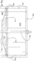
- Vorrichtung (100) zum Trennen von Korn aus flüssigem Abwasser, während organische Feststoffe in Suspension zurückgehalten werden, umfassend Einlassmittel zum Zugeben von flüssigem Abwasser in die Vorrichtung (100), Auslassmittel zum Entfernen von Flüssigkeit, aus dem das Korn von der Vorrichtung getrennt wurde, und Mittel zum Entfernen des abgeschiedenen Korns aus der Vorrichtung (100), wobei die Vorrichtung (100) ferner aufweist:- eine zylindrische Kornabscheide-Hauptkammer (102), die einen unteren Endabschnitt (110), ein oberes Ende (108) und eine Umfangswand (106) definiert;- eine Kornspeicher-Nebenkammer (104), welche unterhalb des unteren Endabschnitts (110) der Hauptkammer angeordnet ist, sodass sich das aus der Flüssigkeit absetzende Korn in der Nebenkammer (104) absetzt, wobei die Nebenkammer (104) eine zentrale Kornabscheide-Zugangsoberseiteneinmündung aufweist, welche sich in Richtung des unteren Endbereichs (110) der Hauptkammer hin öffnet;- eine vertikale Welle (140), welche zentral in der Hauptkammer (102) und in der Nebenkammer (104) angeordnet ist, wobei die Welle (140) eine Längsachse aufweist;- Antriebsmittel (142), um die vertikale Welle (140) um die Längsachse in eine Drehung zu versetzen;- eine Trennwand (114), welche sich quer durch die Hauptkammer (102) zwischen dem oberen Ende (108) und dem unteren Ende (110) davon beabstandet erstreckt, wobei eine obere Teilkammer (102A) innerhalb der Hauptkammer (102) oberhalb der Trennwand (114) ausgebildet ist und eine untere Teilkammer (102B) in der Hauptkammer unterhalb der Trennwand (114) ausgebildet ist, wobei die Einlassmittel für das flüssige Abwasser in direkter Fluidverbindung mit der unteren Teilkammer (102B) sind, wobei die Auslassmittel für die Flüssigkeit in direkter Fluidverbindung mit der oberen Teilkammer (102A) sind, wobei die Trennwand (114) eine Umfangskante aufweist, die integral im Wesentlichen fluiddicht mit der Umfangswand (106) der Hauptkammer (102) verbunden ist, wobei die Trennwand (114) eine zentrale Bodenöffnung (120) aufweist, welche die Welle (140) umschließt, wobei die zentrale Bodenöffnung (120) der Trennwand (114) von der Welle (140) beabstandet ist, um eine ringförmige Öffnung zwischen der Welle und der Trennwand (114) zu definieren, um eine Aufwärtsströmung der Flüssigkeit von der unteren Teilkammer (102B) zu der oberen Teilkammer (102A) bereitzustellen;- und mechanische Mittel (150), welche innerhalb der Hauptkammer (102) angeordnet sind und einen ersten Fluidstrom des anhaltend rotierenden flüssigen Abwassers innerhalb der unteren Teilkammer (102B) ermöglichen, Herbeiführen eines aufwärts gerichteten zweiten Fluidstromes von der unteren Teilkammer (102B) durch die ringförmige Trennwandöffnung in die obere Teilkammer (102A), und Ermöglichen eines anhaltend rotierenden dritten Fluidstromes innerhalb der oberen Teilkammer (102A) zum Entweichen durch die Auslasseinrichtung,wobei die Vorrichtung (100) dazu eingerichtet ist, um einen Fluiddurchflussgradienten zwischen dem dritten Fluidstrom und dem ersten Fluidstrom zu bewirken und wobei die Vorrichtung dazu eingerichtet ist, dass der dritte Fluidstrom mit einer wesentlich geringeren Geschwindigkeit als der erste Fluidstrom bereitgestellt wird,
wobei die mechanischen Mittel (150) zum Erzeugen des zweiten Fluidstromes und des dritten Fluidstromes eine Vielzahl von Schaufeln (152) aufweisen, die an der Welle (140) befestigt und mit dieser drehbar sind, wobei die Schaufeln (152) in der unteren Teilkammer (102B) angeordnet sind;
wobei die Vorrichtung (100) dazu eingerichtet ist, den Fluiddurchflussgradienten zu bewirken, der eine omnidirektionale, radiale und tangentiale Austrittsströmung der Flüssigkeit, aus der Korn von der oberen Teilkammer (102A) getrennt worden ist, durch die Auslassmittel ermöglicht, und ferner die Vorrichtung (100) dazu eingerichtet ist, um den Fluiddurchflussgradienten zu bewirken, der verschiedene Fluidströmungslasten zwischen dem Einlassmittel und dem Auslassmittel aufnimmt,
wobei die Trennwand (114) ein nach unten konvexer Konus ist, der eine diametral größere obere Öffnung (118) und eine diametral kleinere Bodenöffnung (120) definiert; und wobei das Einlassmittel einen Zugangsanschluss (128), der in der Umfangswand (106) der unteren Teilkammer ausgebildet ist und sich in die untere Teilkammer (102B) hin öffnet, und einen Abwasserzuführkanal (130) aufweist, der sich tangential von der unteren Teilkammer (102B) erstreckt, wobei der Zuführkanal (130) eine Winkelneigung im Bereich zwischen 10° und 30° relativ zu einer Ebene in einem rechten Winkel zu der Umfangswand (106) der unteren Teilkammer hat. - Die Vorrichtung (100) zum Entfernen von Korn nach Anspruch 1, wobei der Durchmesser der konischen Trennwand-Bodenöffnung (120) zwischen 40 und 60 % des Durchmessers der kegelförmigen Trennwand-Oberseitenöffnung (118) darstellt.
- Die Vorrichtung (100) zum Entfernen von Korn nach Anspruch 1 oder 2, wobei die Winkelneigung der kegelförmigen Trennwand (114) in einem Bereich zwischen 15° und 30° liegt.
- Die Vorrichtung (100) zum Entfernen von Korn nach Anspruch 3, wobei der untere Endabschnitt (110) der Hauptkammer trichterförmig ist mit einer Winkelneigung, die im Wesentlichen derjenigen der kegelförmigen Trennwand (114) entspricht, wobei der trichterförmige untere Endabschnitt (110) ein oberes Ende, das sich in die untere Teilkammer (102B) hin öffnet, und ein unteres Ende definiert, das mit der Oberseiteneinmündung der Nebenkammer in Eingriff steht.
- Die Vorrichtung (100) zum Entfernen von Korn nach Anspruch 1 oder 3, wobei der Fluiddurchflussgradient derart gewählt ist, dass die Geschwindigkeit des dritten Fluidstromes etwa viermal kleiner ist als die des ersten Fluidstromes.
- Die Vorrichtung (100) zum Entfernen von Korn nach Anspruch 4, wobei die Schaufeln innerhalb eines Bereiches eingegrenzt sind, der aus der Gruppe ausgewählt ist, umfassend:- innerhalb des unteren Endabschnitts (110) der trichterförmigen Hauptkammer;- innerhalb der Bodenöffnung (120) der konischen Trennwand;- innerhalb der Oberseitenöffnung (118) der konischen Trennwand; undwobei die Schaufeln (152) an einem Registerabschnitt der Welle (140) montiert sind.
- Ein Verfahren zum Entfernen von Korn aus flüssigem Abwasser, während organische Feststoffe in der Suspension zurückgehalten werden, aufweisend Einlassmittel zum Zugeben von flüssigem Abwasser in die Vorrichtung (100), Auslassmittel zum Entfernen von Flüssigkeit, aus der Korn von der Vorrichtung (100) getrennt wurde, und Mittel zum Entfernen des abgeschiedenen Korns aus der Vorrichtung (100), wobei das Verfahren die folgenden Schritte umfasst:Bereitstellen einer zylindrischen Kornabscheide-Hauptkammer (102), welche einen unteren Endabschnitt (110), ein oberes Ende (108) und eine Umfangswand (106) definiert, einer Kornspeicher-Nebenkammer (104), welche unterhalb des unteren Endabschnitts (110) der Hauptkammer angeordnet ist, sodass das Korn sich aus der Flüssigkeit absetzt und sich in der Nebenkammer (104) ablagert, wobei die Nebenkammer (104) eine Umfangswand mit einer oberen Öffnung aufweist; einer vertikale Welle (140), die mittig in der Hauptkammer (102) und in der Nebenkammer (104) angeordnet ist, wobei die Welle (140) eine Längsachse aufweist;Veranlassen einer Drehung der vertikalen Welle (140) um die Längsachse unter Verwendung von Antriebsmitteln (142);Bereitstellen einer Trennwand (114), welche sich quer durch die Hauptkammer (102) zwischen dem oberen Ende (108) und dem unteren Ende (110) davon beabstandet von der Nebenkammer (104) erstreckt, wobei eine obere Teilkammer (102A) in der Hauptkammer (102) oberhalb der Trennwand (114) ausgebildet ist und eine untere Teilkammer (102B) in der Hauptkammer (102) unterhalb der Trennwand (114) ausgebildet ist, wobei das Einlassmittel für das flüssige Abwasser in Fluidverbindung mit der unteren Teilkammer (102B) steht und das Auslassmittel für die Flüssigkeit in Fluidverbindung mit der oberen Teilkammer (102A) steht, wobei die Trennwand (114) eine Umfangskante aufweist, die integral an der Umfangswand (106) der Hauptkammer (102) montiert ist;wobei die Trennwand (114) eine zentrale Bodenöffnung (120) aufweist, welche die Welle (140) umschließt, wobei die Bodenöffnung (120) von der Welle (140) beabstandet ist, um eine ringförmige Öffnung zwischen der Welle (140) und der Trennwand (114) zu definieren, um eine Aufwärtsströmung der Flüssigkeit von der unteren Teilkammer (102B) zu der oberen Teilkammer (102A) zu bewirken;Bereitstellen von Mitteln (150) zum Erzeugen einer anhaltenden rotierenden ersten Fluidströmung des flüssigen Abwassers innerhalb der unteren Teilkammer (102B);Bereitstellen von Mitteln (150) zum Induzieren eines vertikalen aufwärtsgerichteten zweiten Fluidstromes der Flüssigkeit von der unteren Teilkammer (102B) durch die Ringöffnung der Trennwand in die obere Teilkammer (102A);Bereitstellen von Mitteln (150) zum Aufrechthalten eines rotierenden dritten Fluidstromes der Flüssigkeit innerhalb der oberen Teilkammer (102A) zum Ausgeben durch die Auslassmittel; undBereitstellen von Mitteln (150) zum Erzeugen eines Fluiddurchflussgradienten zwischen dem dritten Fluidstrom und dem ersten Fluidstrom;wobei der Fluiddurchfluss des dritten Fluidstromes im Wesentlichen kleiner als der des ersten Fluidstromes ist und dadurch Korn aus dem flüssigen Abwasser entfernt wird.
- Ein Verfahren zum Entfernen von Korn nach Anspruch 7, ferner aufweisend den Schritt des Generierens eines Fluiddurchflussgradienten zwischen dem dritten Fluidstrom und dem ersten Fluidstrom in einem derartigen Ausmaß, dass eine etwa 75 %ige Verringerung der Geschwindigkeit des dritten Fluidstromes relativ zu der des ersten Fluidstromes erreicht wird.
- Ein Verfahren zum Entfernen von Korn nach Anspruch 8, ferner aufweisend die Schritte des radialen Flüssigkeitsaustrittes aus der oberen Teilkammer (102A) durch die Auslassmittel.
- Ein Verfahren zum Entfernen von Korn nach Anspruch 9, ferner umfassend den Schritt des zyklischen Abpumpens von Korn aus der Kornspeicher-Nebenkammer (104), wobei das Abpumpen des Kornes durch einen längsgerichteten Hohlraum in der Welle (140) durchgeführt wird.
- Eine Vorrichtung zum Entfernen von Korn nach Anspruch 1, wobei das Antriebsmittel (142) einen Motor mit konstanter Drehzahl aufweist, der betriebsmäßig mit der Welle (140) verbunden ist.
- Eine Vorrichtung zum Entfernen von Korn nach Anspruch 1, wobei das Antriebsmittel (142) einen Motor mit variabler Drehzahl aufweist, der betriebsmäßig mit der Antriebswelle (140) verbunden ist.
Applications Claiming Priority (2)
| Application Number | Priority Date | Filing Date | Title |
|---|---|---|---|
| US20056008P | 2008-12-01 | 2008-12-01 | |
| PCT/CA2009/001746 WO2010063107A1 (en) | 2008-12-01 | 2009-11-27 | Method and apparatus for sewage grit removal |
Publications (3)
| Publication Number | Publication Date |
|---|---|
| EP2373585A1 EP2373585A1 (de) | 2011-10-12 |
| EP2373585A4 EP2373585A4 (de) | 2012-06-06 |
| EP2373585B1 true EP2373585B1 (de) | 2017-04-05 |
Family
ID=42232838
Family Applications (1)
| Application Number | Title | Priority Date | Filing Date |
|---|---|---|---|
| EP09829920.9A Active EP2373585B1 (de) | 2008-12-01 | 2009-11-27 | Verfahren und vorrichtung zur abwassersandfanggutentfernung |
Country Status (11)
| Country | Link |
|---|---|
| US (1) | US8715511B2 (de) |
| EP (1) | EP2373585B1 (de) |
| CN (1) | CN102224108B (de) |
| BR (1) | BRPI0922140A2 (de) |
| CA (1) | CA2743003C (de) |
| CO (1) | CO6400234A2 (de) |
| DK (1) | DK2373585T3 (de) |
| ES (1) | ES2630219T3 (de) |
| MX (1) | MX2011005818A (de) |
| NZ (1) | NZ593140A (de) |
| WO (1) | WO2010063107A1 (de) |
Families Citing this family (10)
| Publication number | Priority date | Publication date | Assignee | Title |
|---|---|---|---|---|
| US8906233B2 (en) * | 2012-04-16 | 2014-12-09 | Smith & Loveless, Inc. | Ring grit remover with vanes |
| US9334178B2 (en) * | 2012-11-08 | 2016-05-10 | Smith & Loveless Inc. | Vortex-type grit chamber |
| CN102961903B (zh) * | 2012-11-26 | 2014-09-17 | 北京城市排水集团有限责任公司 | 一种带导流筒的旋流沉砂池 |
| CN104138796B (zh) * | 2014-07-21 | 2016-08-17 | 江苏金沃机械有限公司 | 多转鼓式洗涤分离装置 |
| US9932731B2 (en) | 2014-08-11 | 2018-04-03 | Smith & Loveless Inc. | Ring grit remover |
| US9770722B1 (en) | 2016-05-23 | 2017-09-26 | Envirodyne Systems Inc. | Low headloss feed devices and control methods for tray-type vortex grit removal systems |
| DE102016218051A1 (de) * | 2016-09-20 | 2018-03-22 | bioenergy concept GmbH | Behälter und Biogasanlage |
| CN106492520B (zh) * | 2016-12-06 | 2018-07-10 | 沈阳农业大学 | 一种砂水分离装置及方法 |
| US20210284552A1 (en) * | 2018-07-23 | 2021-09-16 | Veolia Water Solutions & Technologies Support | Vortex grit removal apparatus with eddy generator |
| WO2023055369A1 (en) * | 2021-09-30 | 2023-04-06 | Smith & Loveless Inc. | Circular grit remover with tube settlers |
Family Cites Families (24)
| Publication number | Priority date | Publication date | Assignee | Title |
|---|---|---|---|---|
| US2352772A (en) | 1937-05-18 | 1944-07-04 | Dorr Co Inc | Treatment of impure liquids |
| US2491801A (en) * | 1946-06-05 | 1949-12-20 | Debrey Michael | Centrifugal liquid cleaner |
| FR1519392A (fr) | 1966-11-18 | 1968-03-29 | Pista Sa | Installation de dessablage |
| CH548795A (de) | 1972-09-12 | 1974-05-15 | Escher Wyss Ag | Dekanter. |
| US3941698A (en) | 1974-02-19 | 1976-03-02 | Ecodyne Corporation | Grit selector |
| US4107038A (en) | 1977-08-12 | 1978-08-15 | Ecodyne Corporation | Method and apparatus for removing grit |
| GB8332007D0 (en) | 1983-11-30 | 1984-01-04 | Blue Circle Ind Plc | Clarifier |
| US4519907A (en) | 1983-12-19 | 1985-05-28 | Rexnord Inc. | Grit settling basin including vane pump |
| GB2158741B (en) | 1984-05-14 | 1988-08-17 | Hydro Int Ltd | Separation of components of a fluid mixture |
| DE3615747A1 (de) | 1986-05-09 | 1987-11-12 | Bielefeldt Ernst August | Verfahren zum trennen und/oder abscheiden von festen und/oder fluessigen partikeln mit einem wirbelkammerabscheider mit tauchrohr und wirbelkammerabscheider zur durchfuehrung des verfahrens |
| US4767532A (en) * | 1987-05-21 | 1988-08-30 | Smith & Loveless, Inc. | Apparatus for removing grit |
| GB2223957B (en) | 1988-10-07 | 1992-08-12 | Hydro Int Ltd | Separator |
| GB9005418D0 (en) | 1990-03-10 | 1990-05-09 | Hydraulic Design Ltd | Method and apparatus for removing grit from sewage |
| US5116488A (en) | 1990-08-28 | 1992-05-26 | Kamyr, Inc. | Gas sparged centrifugal device |
| US5158678A (en) | 1990-09-28 | 1992-10-27 | Broussard Paul C Sr | Water clarification method and apparatus |
| AUPM628594A0 (en) | 1994-06-17 | 1994-07-07 | Blanche, Paul | An apparatus for the separation of solids from flowing liquid |
| US5569379A (en) | 1994-07-11 | 1996-10-29 | Schloss Engineered Equipment, Inc. | Grit collector for waste water treatment facility |
| US6171498B1 (en) | 1998-03-10 | 2001-01-09 | Chicago Bridge & Iron Company | Upflow water clarifier with central pier |
| US6645382B1 (en) | 2000-11-13 | 2003-11-11 | George E. Wilson | Energy-efficient head cell entry duct |
| US6881350B2 (en) | 2001-03-22 | 2005-04-19 | George E. Wilson | Apparatus and methods for collecting and transferring solids separated from wastewater |
| GB0323613D0 (en) | 2003-10-09 | 2003-11-12 | Jones & Attwood Ltd | Grit trap |
| CN2797351Y (zh) * | 2005-01-19 | 2006-07-19 | 冯太和 | 立式污水除泥砂设备 |
| CN100453482C (zh) * | 2006-06-06 | 2009-01-21 | 史宝荣 | 含油泥砂分离净化的工艺方法及设备 |
| US7971732B2 (en) | 2006-11-06 | 2011-07-05 | Smith & Loveless, Inc. | Grit trap for waste water system |
-
2009
- 2009-11-27 MX MX2011005818A patent/MX2011005818A/es active IP Right Grant
- 2009-11-27 ES ES09829920.9T patent/ES2630219T3/es active Active
- 2009-11-27 EP EP09829920.9A patent/EP2373585B1/de active Active
- 2009-11-27 US US13/130,659 patent/US8715511B2/en active Active
- 2009-11-27 CN CN2009801464161A patent/CN102224108B/zh not_active Expired - Fee Related
- 2009-11-27 WO PCT/CA2009/001746 patent/WO2010063107A1/en active Application Filing
- 2009-11-27 CA CA2743003A patent/CA2743003C/en active Active
- 2009-11-27 BR BRPI0922140A patent/BRPI0922140A2/pt not_active Application Discontinuation
- 2009-11-27 NZ NZ593140A patent/NZ593140A/xx not_active IP Right Cessation
- 2009-11-27 DK DK09829920.9T patent/DK2373585T3/en active
-
2011
- 2011-06-15 CO CO11074353A patent/CO6400234A2/es not_active Application Discontinuation
Non-Patent Citations (1)
| Title |
|---|
| None * |
Also Published As
| Publication number | Publication date |
|---|---|
| WO2010063107A1 (en) | 2010-06-10 |
| DK2373585T3 (en) | 2017-07-10 |
| CO6400234A2 (es) | 2012-03-15 |
| BRPI0922140A2 (pt) | 2016-01-05 |
| US20110240568A1 (en) | 2011-10-06 |
| EP2373585A4 (de) | 2012-06-06 |
| CA2743003A1 (en) | 2010-06-10 |
| CA2743003C (en) | 2016-11-22 |
| ES2630219T3 (es) | 2017-08-18 |
| US8715511B2 (en) | 2014-05-06 |
| NZ593140A (en) | 2013-03-28 |
| CN102224108A (zh) | 2011-10-19 |
| MX2011005818A (es) | 2011-09-06 |
| AU2009322028A1 (en) | 2010-06-10 |
| EP2373585A1 (de) | 2011-10-12 |
| CN102224108B (zh) | 2012-12-26 |
Similar Documents
| Publication | Publication Date | Title |
|---|---|---|
| EP2373585B1 (de) | Verfahren und vorrichtung zur abwassersandfanggutentfernung | |
| EP3196469A1 (de) | Stromführungselement für pumpeneintritt | |
| US4767532A (en) | Apparatus for removing grit | |
| US20130043197A1 (en) | Tangential Flow Particle Separator and Method Therefor | |
| US10309090B2 (en) | Ring grit remover | |
| EP2475461B1 (de) | Zentrifugaltrenner und trennverfahren dafür | |
| US6238329B1 (en) | Centrifugal separator for mixed immiscible fluids | |
| AU2009322028B2 (en) | Method and apparatus for sewage grit removal | |
| CN203112606U (zh) | 撬装除砂装置 | |
| JP2020096999A (ja) | ポンプ装置及びサイクロン型水処理装置 | |
| US20210363745A1 (en) | Circular Parallel Plate Grit Remover | |
| CN220176144U (zh) | 一种水利工程用旋流沉沙装置 | |
| CN217202487U (zh) | 一种新型过滤网转鼓固液分离机 | |
| US20240115977A1 (en) | Apparatus with improved grit removal | |
| JPH0112525B2 (de) | ||
| SU1726048A1 (ru) | Осадительна центрифуга | |
| WO2023055369A1 (en) | Circular grit remover with tube settlers | |
| JPH01215316A (ja) | 固液分離装置及びそれ用の二次流強制装置 | |
| CN117138979A (zh) | 一种具有搅拌反应釜功能的离心机装置 |
Legal Events
| Date | Code | Title | Description |
|---|---|---|---|
| PUAI | Public reference made under article 153(3) epc to a published international application that has entered the european phase |
Free format text: ORIGINAL CODE: 0009012 |
|
| 17P | Request for examination filed |
Effective date: 20110527 |
|
| AK | Designated contracting states |
Kind code of ref document: A1 Designated state(s): AT BE BG CH CY CZ DE DK EE ES FI FR GB GR HR HU IE IS IT LI LT LU LV MC MK MT NL NO PL PT RO SE SI SK SM TR |
|
| DAX | Request for extension of the european patent (deleted) | ||
| A4 | Supplementary search report drawn up and despatched |
Effective date: 20120507 |
|
| RIC1 | Information provided on ipc code assigned before grant |
Ipc: C02F 1/38 20060101AFI20120427BHEP Ipc: B01D 21/06 20060101ALI20120427BHEP Ipc: B01D 21/00 20060101ALI20120427BHEP |
|
| 17Q | First examination report despatched |
Effective date: 20151215 |
|
| GRAP | Despatch of communication of intention to grant a patent |
Free format text: ORIGINAL CODE: EPIDOSNIGR1 |
|
| INTG | Intention to grant announced |
Effective date: 20161123 |
|
| GRAJ | Information related to disapproval of communication of intention to grant by the applicant or resumption of examination proceedings by the epo deleted |
Free format text: ORIGINAL CODE: EPIDOSDIGR1 |
|
| GRAS | Grant fee paid |
Free format text: ORIGINAL CODE: EPIDOSNIGR3 |
|
| GRAP | Despatch of communication of intention to grant a patent |
Free format text: ORIGINAL CODE: EPIDOSNIGR1 |
|
| INTC | Intention to grant announced (deleted) | ||
| GRAA | (expected) grant |
Free format text: ORIGINAL CODE: 0009210 |
|
| INTG | Intention to grant announced |
Effective date: 20170222 |
|
| AK | Designated contracting states |
Kind code of ref document: B1 Designated state(s): AT BE BG CH CY CZ DE DK EE ES FI FR GB GR HR HU IE IS IT LI LT LU LV MC MK MT NL NO PL PT RO SE SI SK SM TR |
|
| REG | Reference to a national code |
Ref country code: GB Ref legal event code: FG4D |
|
| REG | Reference to a national code |
Ref country code: CH Ref legal event code: EP |
|
| REG | Reference to a national code |
Ref country code: AT Ref legal event code: REF Ref document number: 881637 Country of ref document: AT Kind code of ref document: T Effective date: 20170415 |
|
| REG | Reference to a national code |
Ref country code: IE Ref legal event code: FG4D |
|
| REG | Reference to a national code |
Ref country code: DE Ref legal event code: R096 Ref document number: 602009045299 Country of ref document: DE |
|
| REG | Reference to a national code |
Ref country code: DK Ref legal event code: T3 Effective date: 20170704 |
|
| REG | Reference to a national code |
Ref country code: SE Ref legal event code: TRGR |
|
| REG | Reference to a national code |
Ref country code: NL Ref legal event code: MP Effective date: 20170405 |
|
| REG | Reference to a national code |
Ref country code: ES Ref legal event code: FG2A Ref document number: 2630219 Country of ref document: ES Kind code of ref document: T3 Effective date: 20170818 |
|
| REG | Reference to a national code |
Ref country code: LT Ref legal event code: MG4D |
|
| REG | Reference to a national code |
Ref country code: NO Ref legal event code: T2 Effective date: 20170405 |
|
| REG | Reference to a national code |
Ref country code: AT Ref legal event code: MK05 Ref document number: 881637 Country of ref document: AT Kind code of ref document: T Effective date: 20170405 |
|
| REG | Reference to a national code |
Ref country code: FR Ref legal event code: PLFP Year of fee payment: 9 |
|
| PG25 | Lapsed in a contracting state [announced via postgrant information from national office to epo] |
Ref country code: NL Free format text: LAPSE BECAUSE OF FAILURE TO SUBMIT A TRANSLATION OF THE DESCRIPTION OR TO PAY THE FEE WITHIN THE PRESCRIBED TIME-LIMIT Effective date: 20170405 |
|
| PG25 | Lapsed in a contracting state [announced via postgrant information from national office to epo] |
Ref country code: HR Free format text: LAPSE BECAUSE OF FAILURE TO SUBMIT A TRANSLATION OF THE DESCRIPTION OR TO PAY THE FEE WITHIN THE PRESCRIBED TIME-LIMIT Effective date: 20170405 Ref country code: GR Free format text: LAPSE BECAUSE OF FAILURE TO SUBMIT A TRANSLATION OF THE DESCRIPTION OR TO PAY THE FEE WITHIN THE PRESCRIBED TIME-LIMIT Effective date: 20170706 Ref country code: LT Free format text: LAPSE BECAUSE OF FAILURE TO SUBMIT A TRANSLATION OF THE DESCRIPTION OR TO PAY THE FEE WITHIN THE PRESCRIBED TIME-LIMIT Effective date: 20170405 Ref country code: AT Free format text: LAPSE BECAUSE OF FAILURE TO SUBMIT A TRANSLATION OF THE DESCRIPTION OR TO PAY THE FEE WITHIN THE PRESCRIBED TIME-LIMIT Effective date: 20170405 |
|
| PG25 | Lapsed in a contracting state [announced via postgrant information from national office to epo] |
Ref country code: IS Free format text: LAPSE BECAUSE OF FAILURE TO SUBMIT A TRANSLATION OF THE DESCRIPTION OR TO PAY THE FEE WITHIN THE PRESCRIBED TIME-LIMIT Effective date: 20170805 Ref country code: BG Free format text: LAPSE BECAUSE OF FAILURE TO SUBMIT A TRANSLATION OF THE DESCRIPTION OR TO PAY THE FEE WITHIN THE PRESCRIBED TIME-LIMIT Effective date: 20170705 Ref country code: PL Free format text: LAPSE BECAUSE OF FAILURE TO SUBMIT A TRANSLATION OF THE DESCRIPTION OR TO PAY THE FEE WITHIN THE PRESCRIBED TIME-LIMIT Effective date: 20170405 Ref country code: LV Free format text: LAPSE BECAUSE OF FAILURE TO SUBMIT A TRANSLATION OF THE DESCRIPTION OR TO PAY THE FEE WITHIN THE PRESCRIBED TIME-LIMIT Effective date: 20170405 |
|
| REG | Reference to a national code |
Ref country code: DE Ref legal event code: R097 Ref document number: 602009045299 Country of ref document: DE |
|
| PG25 | Lapsed in a contracting state [announced via postgrant information from national office to epo] |
Ref country code: EE Free format text: LAPSE BECAUSE OF FAILURE TO SUBMIT A TRANSLATION OF THE DESCRIPTION OR TO PAY THE FEE WITHIN THE PRESCRIBED TIME-LIMIT Effective date: 20170405 Ref country code: SK Free format text: LAPSE BECAUSE OF FAILURE TO SUBMIT A TRANSLATION OF THE DESCRIPTION OR TO PAY THE FEE WITHIN THE PRESCRIBED TIME-LIMIT Effective date: 20170405 Ref country code: RO Free format text: LAPSE BECAUSE OF FAILURE TO SUBMIT A TRANSLATION OF THE DESCRIPTION OR TO PAY THE FEE WITHIN THE PRESCRIBED TIME-LIMIT Effective date: 20170405 Ref country code: CZ Free format text: LAPSE BECAUSE OF FAILURE TO SUBMIT A TRANSLATION OF THE DESCRIPTION OR TO PAY THE FEE WITHIN THE PRESCRIBED TIME-LIMIT Effective date: 20170405 |
|
| PGFP | Annual fee paid to national office [announced via postgrant information from national office to epo] |
Ref country code: FI Payment date: 20171012 Year of fee payment: 9 |
|
| PLBE | No opposition filed within time limit |
Free format text: ORIGINAL CODE: 0009261 |
|
| STAA | Information on the status of an ep patent application or granted ep patent |
Free format text: STATUS: NO OPPOSITION FILED WITHIN TIME LIMIT |
|
| PG25 | Lapsed in a contracting state [announced via postgrant information from national office to epo] |
Ref country code: SM Free format text: LAPSE BECAUSE OF FAILURE TO SUBMIT A TRANSLATION OF THE DESCRIPTION OR TO PAY THE FEE WITHIN THE PRESCRIBED TIME-LIMIT Effective date: 20170405 Ref country code: IT Free format text: LAPSE BECAUSE OF FAILURE TO SUBMIT A TRANSLATION OF THE DESCRIPTION OR TO PAY THE FEE WITHIN THE PRESCRIBED TIME-LIMIT Effective date: 20170405 |
|
| PGFP | Annual fee paid to national office [announced via postgrant information from national office to epo] |
Ref country code: ES Payment date: 20171220 Year of fee payment: 9 |
|
| 26N | No opposition filed |
Effective date: 20180108 |
|
| PG25 | Lapsed in a contracting state [announced via postgrant information from national office to epo] |
Ref country code: SI Free format text: LAPSE BECAUSE OF FAILURE TO SUBMIT A TRANSLATION OF THE DESCRIPTION OR TO PAY THE FEE WITHIN THE PRESCRIBED TIME-LIMIT Effective date: 20170405 |
|
| REG | Reference to a national code |
Ref country code: DE Ref legal event code: R119 Ref document number: 602009045299 Country of ref document: DE |
|
| PG25 | Lapsed in a contracting state [announced via postgrant information from national office to epo] |
Ref country code: MC Free format text: LAPSE BECAUSE OF FAILURE TO SUBMIT A TRANSLATION OF THE DESCRIPTION OR TO PAY THE FEE WITHIN THE PRESCRIBED TIME-LIMIT Effective date: 20170405 |
|
| GBPC | Gb: european patent ceased through non-payment of renewal fee |
Effective date: 20171127 |
|
| PG25 | Lapsed in a contracting state [announced via postgrant information from national office to epo] |
Ref country code: LI Free format text: LAPSE BECAUSE OF NON-PAYMENT OF DUE FEES Effective date: 20171130 Ref country code: CH Free format text: LAPSE BECAUSE OF NON-PAYMENT OF DUE FEES Effective date: 20171130 |
|
| PG25 | Lapsed in a contracting state [announced via postgrant information from national office to epo] |
Ref country code: LU Free format text: LAPSE BECAUSE OF NON-PAYMENT OF DUE FEES Effective date: 20171127 |
|
| REG | Reference to a national code |
Ref country code: BE Ref legal event code: MM Effective date: 20171130 |
|
| REG | Reference to a national code |
Ref country code: IE Ref legal event code: MM4A |
|
| PG25 | Lapsed in a contracting state [announced via postgrant information from national office to epo] |
Ref country code: MT Free format text: LAPSE BECAUSE OF NON-PAYMENT OF DUE FEES Effective date: 20171127 |
|
| PG25 | Lapsed in a contracting state [announced via postgrant information from national office to epo] |
Ref country code: IE Free format text: LAPSE BECAUSE OF NON-PAYMENT OF DUE FEES Effective date: 20171127 Ref country code: DE Free format text: LAPSE BECAUSE OF NON-PAYMENT OF DUE FEES Effective date: 20180602 |
|
| PG25 | Lapsed in a contracting state [announced via postgrant information from national office to epo] |
Ref country code: GB Free format text: LAPSE BECAUSE OF NON-PAYMENT OF DUE FEES Effective date: 20171127 Ref country code: BE Free format text: LAPSE BECAUSE OF NON-PAYMENT OF DUE FEES Effective date: 20171130 |
|
| PG25 | Lapsed in a contracting state [announced via postgrant information from national office to epo] |
Ref country code: HU Free format text: LAPSE BECAUSE OF FAILURE TO SUBMIT A TRANSLATION OF THE DESCRIPTION OR TO PAY THE FEE WITHIN THE PRESCRIBED TIME-LIMIT; INVALID AB INITIO Effective date: 20091127 |
|
| PG25 | Lapsed in a contracting state [announced via postgrant information from national office to epo] |
Ref country code: FI Free format text: LAPSE BECAUSE OF NON-PAYMENT OF DUE FEES Effective date: 20181127 |
|
| PG25 | Lapsed in a contracting state [announced via postgrant information from national office to epo] |
Ref country code: CY Free format text: LAPSE BECAUSE OF NON-PAYMENT OF DUE FEES Effective date: 20170405 |
|
| PGFP | Annual fee paid to national office [announced via postgrant information from national office to epo] |
Ref country code: SE Payment date: 20190925 Year of fee payment: 11 Ref country code: NO Payment date: 20190926 Year of fee payment: 11 |
|
| PG25 | Lapsed in a contracting state [announced via postgrant information from national office to epo] |
Ref country code: MK Free format text: LAPSE BECAUSE OF FAILURE TO SUBMIT A TRANSLATION OF THE DESCRIPTION OR TO PAY THE FEE WITHIN THE PRESCRIBED TIME-LIMIT Effective date: 20170405 |
|
| REG | Reference to a national code |
Ref country code: ES Ref legal event code: FD2A Effective date: 20200108 |
|
| PG25 | Lapsed in a contracting state [announced via postgrant information from national office to epo] |
Ref country code: ES Free format text: LAPSE BECAUSE OF NON-PAYMENT OF DUE FEES Effective date: 20181128 |
|
| PGFP | Annual fee paid to national office [announced via postgrant information from national office to epo] |
Ref country code: DK Payment date: 20191121 Year of fee payment: 11 |
|
| PG25 | Lapsed in a contracting state [announced via postgrant information from national office to epo] |
Ref country code: TR Free format text: LAPSE BECAUSE OF FAILURE TO SUBMIT A TRANSLATION OF THE DESCRIPTION OR TO PAY THE FEE WITHIN THE PRESCRIBED TIME-LIMIT Effective date: 20170405 |
|
| PG25 | Lapsed in a contracting state [announced via postgrant information from national office to epo] |
Ref country code: PT Free format text: LAPSE BECAUSE OF FAILURE TO SUBMIT A TRANSLATION OF THE DESCRIPTION OR TO PAY THE FEE WITHIN THE PRESCRIBED TIME-LIMIT Effective date: 20170405 |
|
| REG | Reference to a national code |
Ref country code: NO Ref legal event code: MMEP Ref country code: DK Ref legal event code: EBP Effective date: 20201130 |
|
| REG | Reference to a national code |
Ref country code: SE Ref legal event code: EUG |
|
| PG25 | Lapsed in a contracting state [announced via postgrant information from national office to epo] |
Ref country code: NO Free format text: LAPSE BECAUSE OF NON-PAYMENT OF DUE FEES Effective date: 20201130 |
|
| PG25 | Lapsed in a contracting state [announced via postgrant information from national office to epo] |
Ref country code: SE Free format text: LAPSE BECAUSE OF NON-PAYMENT OF DUE FEES Effective date: 20201128 |
|
| PG25 | Lapsed in a contracting state [announced via postgrant information from national office to epo] |
Ref country code: DK Free format text: LAPSE BECAUSE OF NON-PAYMENT OF DUE FEES Effective date: 20201130 |
|
| P01 | Opt-out of the competence of the unified patent court (upc) registered |
Effective date: 20230526 |
|
| PGFP | Annual fee paid to national office [announced via postgrant information from national office to epo] |
Ref country code: FR Payment date: 20231117 Year of fee payment: 15 |