EP2373585B1 - Method and apparatus for sewage grit removal - Google Patents
Method and apparatus for sewage grit removal Download PDFInfo
- Publication number
- EP2373585B1 EP2373585B1 EP09829920.9A EP09829920A EP2373585B1 EP 2373585 B1 EP2373585 B1 EP 2373585B1 EP 09829920 A EP09829920 A EP 09829920A EP 2373585 B1 EP2373585 B1 EP 2373585B1
- Authority
- EP
- European Patent Office
- Prior art keywords
- grit
- fluid flow
- partition
- liquid
- subchamber
- Prior art date
- Legal status (The legal status is an assumption and is not a legal conclusion. Google has not performed a legal analysis and makes no representation as to the accuracy of the status listed.)
- Active
Links
- 239000010865 sewage Substances 0.000 title claims description 38
- 238000000034 method Methods 0.000 title claims description 13
- 239000012530 fluid Substances 0.000 claims description 101
- 239000007788 liquid Substances 0.000 claims description 76
- 238000005192 partition Methods 0.000 claims description 68
- 230000002093 peripheral effect Effects 0.000 claims description 21
- 238000004891 communication Methods 0.000 claims description 9
- 239000007787 solid Substances 0.000 claims description 7
- 230000001939 inductive effect Effects 0.000 claims description 4
- 239000000725 suspension Substances 0.000 claims description 4
- 230000002459 sustained effect Effects 0.000 claims description 4
- 238000005086 pumping Methods 0.000 claims 2
- XLYOFNOQVPJJNP-UHFFFAOYSA-N water Substances O XLYOFNOQVPJJNP-UHFFFAOYSA-N 0.000 description 9
- 238000009408 flooring Methods 0.000 description 5
- 230000000630 rising effect Effects 0.000 description 5
- 239000000463 material Substances 0.000 description 4
- 239000004576 sand Substances 0.000 description 4
- 238000004062 sedimentation Methods 0.000 description 3
- 241000209149 Zea Species 0.000 description 2
- 235000005824 Zea mays ssp. parviglumis Nutrition 0.000 description 2
- 235000002017 Zea mays subsp mays Nutrition 0.000 description 2
- 235000005822 corn Nutrition 0.000 description 2
- 230000000694 effects Effects 0.000 description 2
- 239000002245 particle Substances 0.000 description 2
- 238000000926 separation method Methods 0.000 description 2
- 238000004065 wastewater treatment Methods 0.000 description 2
- 239000003818 cinder Substances 0.000 description 1
- 239000011362 coarse particle Substances 0.000 description 1
- 238000005094 computer simulation Methods 0.000 description 1
- 238000010276 construction Methods 0.000 description 1
- 238000000151 deposition Methods 0.000 description 1
- 230000002708 enhancing effect Effects 0.000 description 1
- 238000005189 flocculation Methods 0.000 description 1
- 230000016615 flocculation Effects 0.000 description 1
- 230000005484 gravity Effects 0.000 description 1
- 239000004519 grease Substances 0.000 description 1
- 229910052500 inorganic mineral Inorganic materials 0.000 description 1
- 239000011707 mineral Substances 0.000 description 1
- 238000005457 optimization Methods 0.000 description 1
- 239000013049 sediment Substances 0.000 description 1
- 239000010802 sludge Substances 0.000 description 1
- 239000002689 soil Substances 0.000 description 1
- 230000007704 transition Effects 0.000 description 1
- 238000011144 upstream manufacturing Methods 0.000 description 1
Images


Classifications
-
- B—PERFORMING OPERATIONS; TRANSPORTING
- B01—PHYSICAL OR CHEMICAL PROCESSES OR APPARATUS IN GENERAL
- B01D—SEPARATION
- B01D21/00—Separation of suspended solid particles from liquids by sedimentation
- B01D21/0087—Settling tanks provided with means for ensuring a special flow pattern, e.g. even inflow or outflow
-
- B—PERFORMING OPERATIONS; TRANSPORTING
- B01—PHYSICAL OR CHEMICAL PROCESSES OR APPARATUS IN GENERAL
- B01D—SEPARATION
- B01D21/00—Separation of suspended solid particles from liquids by sedimentation
- B01D21/003—Sedimentation tanks provided with a plurality of compartments separated by a partition wall
-
- B—PERFORMING OPERATIONS; TRANSPORTING
- B01—PHYSICAL OR CHEMICAL PROCESSES OR APPARATUS IN GENERAL
- B01D—SEPARATION
- B01D21/00—Separation of suspended solid particles from liquids by sedimentation
- B01D21/0039—Settling tanks provided with contact surfaces, e.g. baffles, particles
-
- B—PERFORMING OPERATIONS; TRANSPORTING
- B01—PHYSICAL OR CHEMICAL PROCESSES OR APPARATUS IN GENERAL
- B01D—SEPARATION
- B01D21/00—Separation of suspended solid particles from liquids by sedimentation
- B01D21/02—Settling tanks with single outlets for the separated liquid
-
- B—PERFORMING OPERATIONS; TRANSPORTING
- B01—PHYSICAL OR CHEMICAL PROCESSES OR APPARATUS IN GENERAL
- B01D—SEPARATION
- B01D21/00—Separation of suspended solid particles from liquids by sedimentation
- B01D21/24—Feed or discharge mechanisms for settling tanks
-
- B—PERFORMING OPERATIONS; TRANSPORTING
- B01—PHYSICAL OR CHEMICAL PROCESSES OR APPARATUS IN GENERAL
- B01D—SEPARATION
- B01D21/00—Separation of suspended solid particles from liquids by sedimentation
- B01D21/24—Feed or discharge mechanisms for settling tanks
- B01D21/2405—Feed mechanisms for settling tanks
- B01D21/2411—Feed mechanisms for settling tanks having a tangential inlet
-
- B—PERFORMING OPERATIONS; TRANSPORTING
- B01—PHYSICAL OR CHEMICAL PROCESSES OR APPARATUS IN GENERAL
- B01D—SEPARATION
- B01D21/00—Separation of suspended solid particles from liquids by sedimentation
- B01D21/24—Feed or discharge mechanisms for settling tanks
- B01D21/2427—The feed or discharge opening located at a distant position from the side walls
-
- B—PERFORMING OPERATIONS; TRANSPORTING
- B01—PHYSICAL OR CHEMICAL PROCESSES OR APPARATUS IN GENERAL
- B01D—SEPARATION
- B01D21/00—Separation of suspended solid particles from liquids by sedimentation
- B01D21/24—Feed or discharge mechanisms for settling tanks
- B01D21/245—Discharge mechanisms for the sediments
-
- B—PERFORMING OPERATIONS; TRANSPORTING
- B01—PHYSICAL OR CHEMICAL PROCESSES OR APPARATUS IN GENERAL
- B01D—SEPARATION
- B01D21/00—Separation of suspended solid particles from liquids by sedimentation
- B01D21/26—Separation of sediment aided by centrifugal force or centripetal force
-
- C—CHEMISTRY; METALLURGY
- C02—TREATMENT OF WATER, WASTE WATER, SEWAGE, OR SLUDGE
- C02F—TREATMENT OF WATER, WASTE WATER, SEWAGE, OR SLUDGE
- C02F1/00—Treatment of water, waste water, or sewage
- C02F1/38—Treatment of water, waste water, or sewage by centrifugal separation
Landscapes
- Chemical & Material Sciences (AREA)
- Chemical Kinetics & Catalysis (AREA)
- Separation Of Solids By Using Liquids Or Pneumatic Power (AREA)
- Physical Water Treatments (AREA)
- Extraction Or Liquid Replacement (AREA)
Description
- This application claims the conventional priority of
United States Provisional patent application N° 61/200,560 filed on December 1, 2008 - In sewage treatment plants, heavy mineral matter called "grit," forms part of the fluids that need to be processed and segregated from other fluid material. Grit is principally made up of sand and soil, but can also contain cinders, coffee grounds, seeds, corn, and other coarse sediments. As grit cannot be treated, reduced in size or eliminated by treatment methods, it needs to be physically removed. Grit presents a problem to wastewater treatment as it is hard and abrasive; it wears pumps and other mechanical devices; it is heavy and accumulates in clarifiers, treatment basins, digesters, et al, where it must often be removed by hand.
-
United States patent N° 4,767,532 issued in August 30, 1988 to Smith & Loveless inc., discloses a grit selector having an upper settling chamber and a lower grit storage chamber. The settling chamber communicates with the grit storage chamber through an opening in a transition surface there between. An influent flume directs influent liquid directly into a lower portion of the settling chamber. An effluent flume withdraws effluent liquid from an upper portion of the settling chamber. The influent flume and effluent flume have a common centerline with the effluent flume being positioned at an elevation above the influent flume. A baffle member extends into the settling chamber for directing the influent liquid stream outwardly towards a lower portion of the periphery of the settling chamber. Influent fluid forcibly flows into the settling chamber in a tangential fashion, which induces rotational circulation inside the settling chamber. A rotating blade sustains the rotational circulation brought about initially by the incoming tangential fluid flow. Evacuation of sand and other grit material is done mainly under gravity into bottom grit pit, while water escape is performed once again under tangential flow bias. - It is also known from
US2,491,801 a device for centrifugally separating foreign matter from a liquid and depositing the separated foreign matter, or sludge, in a sump, from which it may be periodically drained to keep the device in perfect working condition. It is also known fromUS2,352,772 , methods and apparatus for the treatment of turbid liquids, such as water and sewage, by the separation therefrom of settled solids by flocculation and sedimentation. - A problem with some prior art grit removal apparatuses relates to design limitations in the orientation and size of the effluent flume liquid flow channel exiting from the apparatus settling chamber, compared to the influent flume liquid sewage flow channel. In particular, design borne flow load limitations require that:
- 1. the inner diameter of the effluent flume flow channel be substantially the same as the inner diameter of the influent flume flow channel; and
- 2. the general orientation and flow direction of the effluent flume flow channel be the same as that of the influent flume flow channel, i.e. no angular deviation (e.g. a right angle deviation) from the flow direction of the influent flume flow channel is allowed relative to the flow direction of the effluent flume flow channel, for the prior art grit removal apparatus to remain operational.
- The invention relates to an apparatus, according to apparatus claims, for separating grit from liquid sewage while retaining organic solids in suspension. Said apparatus includes inlet means for admitting liquid sewage into the apparatus, outlet means for removing liquid from which grit has been separated from the apparatus, and means for removing separated grit from the apparatus, the apparatus further comprising : - a cylindrical grit settling main chamber defining a bottom end portion, a top end and a peripheral wall; - a grit storage secondary chamber positioned below the main chamber bottom end portion such that grit settling out of the liquid will settle into said secondary chamber, said secondary chamber including a central grit settling access top mouth opening through said main chamber bottom end portion; - a vertical shaft positioned centrally in said main chamber and in said secondary chamber, said shaft having a longitudinal axis; - means for causing rotation of said vertical shaft about said longitudinal axis; - a partition extending transversely through said main chamber intermediate said top end and said bottom end thereof spacedly therefrom wherein an upper subchamber is formed in said main chamber above said partition and a lower subchamber is formed in said main chamber below said partition, said liquid sewage inlet means in direct fluid communication with said lower sub-chamber, said liquid outlet means in direct fluid communication with said upper sub-chamber, said partition having a peripheral edge integrally mounted in substantially fluid tight fashion to said peripheral wall of said main chamber; said partition including a bottom central aperture housing said shaft, said partition bottom central aperture being spaced from said shaft to define an annular opening between said shaft and said partition to provide for upward flow of liquid from said lower subchamber to said upper subchamber; and mechanical means positioned within said main chamber and enabling sustained rotational liquid sewage first fluid flow within said lower subchamber, enabling inducing upward liquid second fluid flow from said lower subchamber through said partition annular opening and into said upper subchamber, and enabling sustaining rotational liquid third fluid flow within said upper subchamber for escape through said outlet means, wherein the apparatus is arranged to provide a fluid flow speed gradient between said third fluid flow and said first fluid flow.
- The apparatus is arranged to provide said fluid flow speed gradient such that said third fluid flow is at substantially smaller speed than said first fluid flow, with said third fluid flow speed being preferably about four times smaller than that of said first fluid flow.
- Said mechanical means for causing said second fluid flow and said third fluid flow includes a plurality of vanes fixed to said shaft and rotatable therewith, said vanes located within said lower subchamber; wherein the apparatus is arranged to provide said fluid flow speed gradient enabling omnidirectional radial or tangential escape flow of the liquid from which grit has been separated from said upper subchamber through said outlet means, and furthermore the apparatus is arranged to provide said fluid flow speed gradient accommodating differential fluid flow loads between said inlet means and said outlet means.
- According to an embodiment not according to the invention, said vanes are located within said upper subchamber.
- Said partition is a downwardly convex cone with a diametrally smaller bottom mouth and a diametrally larger top mouth. Preferably, the bottom mouth diameter of said conical partition represents between 40 and 60 % of the diameter of said conical partition top mouth, and preferably about 50% thereof. The angular slope of said conical partition could range between 15° and 30°, with optimal value at 20°.
- The main chamber bottom end portion is preferably funnel shaped with an angular slope substantially matching that of said conical partition, preferably having an angular slope of about 20°.
- Said inlet means includes an access port made in said lower sub-chamber peripheral wall and opening into said lower subchamber, and a liquid sewage supply channel tangentially projecting from said lower subchamber, said supply channel having an angular slope ranging between 10° and 30° (optimal value being 15°) relative to a plane at right angle to said lower subchamber peripheral wall.
- Alternately, not according to the invention, said partition is a flat panel.
- Alternately, said vanes are circumscribed within said funnel shaped main chamber bottom end portion and mounted to a registering portion of said shaft.
- The invention also relates to a method for removing grit from liquid sewage while retaining organic solids in suspension according to method claims. Said method includes inlet means for admitting liquid sewage into the apparatus, outlet means for removing liquid from which grit has been separated from the apparatus, and means for removing separated grit from the apparatus, the method comprising the following steps : - providing a cylindrical grit settling main chamber defining a bottom end, a top end and a peripheral wall, a grit storage secondary chamber positioned below the main chamber such that grit settling out of the liquid will settle into said secondary chamber, said secondary chamber including a peripheral wall having an upper mouth; a vertical shaft positioned centrally in said main chamber and in said secondary chamber, said shaft having a longitudinal axis; - causing rotation of said vertical shaft about said longitudinal axis; - providing a partition extending transversely through said main chamber intermediate said top end and said bottom end thereof spacedly from said secondary chamber wherein an upper subchamber is formed in said main chamber above said partition and a lower subchamber is formed in said main chamber below said partition, wherein said liquid sewage inlet means is in fluid communication with said lower sub-chamber, and said liquid outlet means is in fluid communication with said upper sub-chamber, said partition having a peripheral edge integrally mounted to said peripheral wall of said main chamber; said partition including a bottom central aperture housing said shaft, said bottom aperture being spaced from said shaft to define an annular opening between said shaft and said partition to provide for upward flow of liquid from said lower subchamber to said upper subchamber; - - providing means for generating sustained rotational liquid sewage first fluid flow within said lower subchamber; - providing means for inducing vertical upward liquid second fluid flow from said lower subchamber through said partition annular opening and into said upper subchamber; - providing means for sustaining rotational liquid third fluid flow within said upper subchamber for escape through said outlet means; and - providing means for generating a fluid flow speed gradient between said third fluid flow and said first fluid flow.
- In this method, the fluid flow speed gradient of said third fluid flow is substantially smaller than that of said first fluid flow and thereby removing grit from the liquid sewage.
- Preferably, the step of generating a fluid flow speed gradient between said third fluid flow and said first fluid flow, is of such a degree that about a 75% decrease in speed of third fluid flow is achieved relative to that of said first fluid flow.
- Preferably, there is further included the step of radial liquid escape from said upper subchamber through said outlet means.
-
-
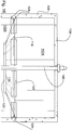
Figure 1 is a top plan view of an embodiment of grit removing apparatus according to the present invention; -
Figures 2-4 are elevational views from three different perspectives of the apparatus offigure 1 ; -
Figures 5-6 are enlarged views offigures 1 and 3 , respectively, showing further detail; -
Figures 7A,7B and 7C are views similar tofigure 2 but at an enlarged scale and showing three different alternate fluid propeller mountings on the vertical shaft relative to the conical partition; -
Figures 8 and 9 are a top plan view similar tofigure 1 and an elevational view similar tofigure 3 , but showing an alternate embodiment (not according to the invention) where the partition is a flat panel; -
Figures 10 to 13 are views similar tofigure 1 , but at a larger scale and showing four different alternate orientations of liquid outlet means channels enabled by the present design of grit removal apparatus; ranges between 40% and 60 % of that oftop flange 118, with optimal value being about 50%. -
Top flange 118 is fixedly connected in substantially fluid tight fashion toupright wall 106, whereinbottom mouth 120 forms a plane generally orthogonal to the main chamberupright wall 106. However, for practical purposes, a functional tolerance of a few millimetres between the partitiontop flange 118 and the main chamberupright wall 106 may be found to be operationally acceptable for mounting purposes. - Preferably, the slope of
conical body 116 matches that offunnel shape flooring 112, with an optimal value of about 20°. A greater angular conicity of theconical partition 114, for example of between 30° to 45°, could theoretically be effective, however that would create substantial increase in grit removal device size and thus in fixed costs, that would reduce or eliminate the cost-savings associated with the improved grit removal capability. - Accordingly, an
upper subchamber 102A is formed between theconical body 116 ofpartition 114 and thetop wall 108 ofmain chamber 102, and alower subchamber 102B is formed between theconical body 116 ofpartition 114 and the funnelshaped flooring 112 ofchamber 102, whereinsubchambers bottom mouth 120 ofconical partition 114.Attachment brackets 122 are fixedly provided edgewisely onflange 118 and are anchored towall 102 byanchor fasteners 124 in substantially fluid tight fashion withelastomeric strips 126 lodged into aperipheral cavity 122A ofbrackets 122. - It is thus understood that
conical partition 114 is sized and shaped relative togrit settling chamber 102 in such a fashion as to restrict all vortex induced upward flow of partially grit-removed water to a water flow only partition bottomcentral mouth 120. Water partially purged from grit is not allowed to flow upwardly between the sealed peripheral edge portion ofconical partition 114 and the peripheralinner wall 106 ofsettling chamber 102, so that all water flow betweensub-chambers central bottom mouth 120. - A
fluid intake port 128 transversely opens throughupright wall 106 and intolower subchamber 102B. A liquidsewage intake channel 130 opens at one end intointake port 128, for ingress intosubchamber 102B of liquid sewage. Channel 130 tangentially intersects the lower portion of mainsettling chamber wall 106 so as to cause the incoming influent sewage liquid to flow tangentially intolower subchamber 102B. A centrifugal force is generated for the sewage fluid engaging inside cylindricallower subchamber 102B, which brings about sewage fluid forcibly radially outwardly against the interior wall ofchamber 102B. - Channel 130 has at is upstream end a generally horizontal
main feeder segment 130A, connecting withchannel 130 via an intermediate downwardly inclinedelbowed section 130B, whereinchannel 130 forms a non-orthogonal angular value withwall 106. Preferably, the angular value ofchannel section 130 relative to a plane orthogonal towall 106 ranges between 10° and 30°, and most preferably having an optimal value of 15°. Accordingly, liquid sewage is designed to flow throughinlet port 128 and intosubchamber 102B at a substantial flow speed. The diametral size offluid inlet port 128 is preferably substantially equal to the distance betweentop flange 118 ofconical partition 114 and thetop mouth 112B offunnel shape flooring 112. - A
fluid outlet port 132 transversely open throughupright wall 106 and intoupper subchamber 102A. Aliquid channel 134 transversely opens at one end intofluid outlet port 132, for outflow escape of liquid separated from grit fromupper subchamber 102A and intochannel 134. As suggested infigure 6 , the inner diameter ofliquid outflow channel 134 may be substantially larger than that offluid intake channel 130 and may remain in the same general direction than the latter in this operational design. - Alternately, as suggested by the embodiment of
figure 10 , liquid outflow channel 134' of grit removal apparatus 100' may operationally become reoriented by 180° relative to the direction ofintake channel 130. Moreover, as also illustrated infigure 10 , the liquid outflow channel 134' need not escape tangentially from wall 106', as with the previous embodiment, but may escape radially therefrom and for example in parallel counterflow fashion to channel 130 while grit removing apparatus 100' remains fully operational. - Still alternately, as suggested by the embodiment of
figure 11 ,channels 130", 134" ofgrit removal apparatus 100" may be coaxial. The alternate operational embodiment offigure 12 is similar tofigure 10 , except that thechannels 130"', 134"' ofgrit removal apparatus 100"' have substantially same inner diameter. The alternate embodiment ofgrit removal apparatus 100"" offigure 13 shows a operational design where theliquid outlet channel 134"" escapes tangentially frommain chamber wall 106"" at right angle relative to the direction ofsewage intake channel 130"". - A
hollow shaft 140 is mounted in upright condition withinmain chamber 102, defining atop end portion 140A journalled intotop wall 108 through anaperture 108A, and sized so that itsbottom end mouth 108B open freely intogrit storage chamber 104 in such a way as to be able to reach most of the grit material sedimentation therein.Shaft 140 extends freely throughmouths conical partition 114. Amotor 142 carried overwall 108 is operatively connected toshaft 140 and drives same into rotation. The gear box of theshaft motor 142 will preferably be manufactured from a heavy bearing support plate and structural members. It shall be designed so that the gears and bearings be easily grease lubricated. The lower portion of the case could be closed with an anti-splash plate. The gear case could include a pinion mounted directly on the gear motor's output shaft and riding on for example a 495 mm pitch diameter slewing ring having external gearing. Preferably, themotor 142 is of the constant speed type, but could alternately be of the variable speed type. - A
fluid pump 144 is also carried bytop wall 108adjacent motor 142, and is operatively connected tohollow shaft 140 and generates negative pressure therein for upwardly pulling grit material fromgrit storage chamber 104 through the hollow ofshaft 140 and outwardly at the top mouth ofshaft 140 to achannel 146 leading to an external refuse collector. Operation offluid pump 144 may be cyclical, for example 15 minutes each hour. - A
multibladed propeller 150 having a number of peripherally mountedblades 152 is transversely fixedly mounted ontoshaft 140 for rotation about a vertical axis centered in settlingchamber 102. In the preferred embodiment offigure 6 ,propeller 150 is mounted intolower subchamber 102B, above funnel shape flooringtop mouth 112B and below thebottom mouth 120 ofconical partition 114, in transverse register with thefluid inlet port 128, wherein the liquid sewage flow fromchannel 130 is directed tangentially toward thepropeller blades 152. Preferably,propeller 150 is sized so that it diametrally matches the diameter of conicalpartition bottom mouth 120. The size of thepartition mouths propeller 150 by removal oftop wall 108 ofmain chamber 102. Theblades 152 are mounted in slightly tilted fashion, for example by about 30° relative to the horizontal plane. - The preferred embodiment of
grit removal apparatus 100 shown infigure 6 operatively enables the various angular tangential or radial mountings of theliquid outlet channel 134, in view in particular of the location of thepropeller 150 being located in thelower subchamber 102B. Thepropeller 150 thus induces a turbine effect in thelower subchamber 102B, generating a rising central vortex (along arrows R1 infig. 15 ). In a rising vortex, the liquid part of the fluid rises along arrows R2 infig. 15 ) but the coarse solids slide toward the bottom along the downwardly inwardly inclined slope of thefunnel shape flooring 112 toward thegrit storage chamber 104. The tangential speed of theblades 152 ofrotating propeller 150 should preferably be the same as that of the liquid sewage flow coming from theinlet channel 130, for example by about one meter per second flow speed and 1.2 cubic meter per second flow volume. Alternately, thepropeller 150 may rotate at a greater speed than that of the sewage flow from theinlet channel 130, for example up to several times the sewage flow speed frominlet channel 130, while still remaining at least partially effective to enhance the rising vortex motion of not only the liquid part but also the organic solids having a lower density than sand (e.g., corn particles). Coarse particles may rotate for example 5 to 6 times or more in thelower sub-chamber 102B, before escaping upwardly through theconical partition mouths upper subchamber 102A, (arrows R3 infig. 15 ) and one important function of thepropeller 150 is to provide optimization of this rising vortex fluid motion. The direction of rotation ofpropeller 150 should be in the same direction as the sewage liquid flow direction. -
Figures 7A, 7B and 7C show alternate mountings forpropeller 150. - In the embodiment of
figure 7A , propeller 150' is mounted withinupper subchamber 102A, aboveconical partition 114 and belowtop wall 108. Propeller 150' includesrocker mountings 151 for each of the blades 152', with saidrocker mountings 151 enabling partial radially outward tilting of the blades 152' from a stationary downwardly extending condition (as illustrated) to a partly radially outwardly extended operative condition, for example by up to 60° from the horizontal plane. The purpose of suchblade rocker mountings 151 is to mitigate drag inertia at the start of the operating cycle, and accordingly, suchblade rocker mountings 151 can operate only in an environment corresponding to theupper subchamber 102A. In this embodiment offigure 7A , the speed gradient between theupper subchamber 102A and thelower subchamber 102B is substantially smaller than with the embodiment offigure 6 where the propeller is mounted within thelower subchamber 102B. The embodiment of grit removal apparatuses offigures 10-13 are therefore not suitable for use with the propeller mounting offigure 7A . - In the second embodiment of
figure 7B ,propeller 150" is again mounted intoupper subchamber 102A, with similar limitations as withfigure 7A , but now substantially coplanar to thetop flange 118 ofconical partition 114. - In the third embodiment of
figure 7C ,propeller 150"' is mounted intolower subchamber 102B, but now substantially with thebottom mouth 120 ofconical partition 114. Limitations as to speed gradients are similar to those offigure 7A . - As suggested by computer generated fluid dynamic simulation graph illustrated in
figure 17 of the drawings, it has been found that improved efficiency - of the order of 10 to 15 % - in grit removal capability relative to prior art grit removal apparatuses, can be obtained with such a grit removal apparatus of the present invention, in particular with the embodiment having a downwardlyconical partition 114 and apropeller 150 mounted intermediately into thelower subchamber 102B. The efficiency level relates to the difference in grit content in the influent channel, as compared to that in the effluent channel. - Alternately, and as illustrated in
figures 8-9 of the drawings, the partition 114' could be planar, instead of conical, but at a cost of added structural construction difficulty but still unexpected improvement of efficiency compared to prior art, namely, of about 10 to 15 % improved efficiency relative to prior art grit removal devices. When the partition is conical, 114, a substantial unexpected 10 to 15 % improvement in efficiency is achieved compared to prior art grit removal apparatuses. An important consideration here is to have a new partition mounted into a grit removal device settling chamber that separates themain settling chamber 102 into twosub-chambers upper sub-chamber 102A, from which escapes the partially grit-removed water, wherein substantially all water flow from the lower sub-chamber to the upper sub-chamber is enabled through thecentral mouths 118 120, only of thepartition 114. - It has been found that unexpectedly, a fluid flow speed gradient is established between the liquid flow inside the
upper subchamber 102A and the liquid flow inside thelower subchamber 102B. In particular, when thepropeller 150 is located within thelower subchamber 102B, optimal results are achieved wherein the fluid flow speed gradient enables omnidirectional radial or tangential escape flow of the liquid from theupper subchamber 102A through theoutlet port 132, and furthermore accommodates differential fluid flow loads between the inlet channel 1309 andoutlet channel 134. For optimal values, the fluid flow speed gradient is such that the fluid flow speed inside theupper subchamber 102A (arrows R3 infig. 15 ) is about four times smaller than that of the fluid flow speed inside thelower subchamber 102B (arrows R1 infig. 15 ). It is further noted that this speed gradient promotes final gravity-borne sedimentation of sand particles which may have accidentally escaped intoupper subchamber 102A, through the rising vortex and through the partitioncentral mouths present apparatus 100. - It is also noted that the
present apparatus 100 easily accommodates up to 25% increase in sewage fluid flow speed relative to constant speed ofpropeller 150, without significant decrease in grit removal operational efficiency or without significant backflow. The present apparatus has high adaptability to accidental fluctuations in fluid flow parameters or liquid outflow configurations. - Another improvement over prior art grit removal apparatuses relates to fluid level controls inside the main
grit settling chamber 102. In the prior art apparatus, such control was critical in view of avoiding substantial decrease in effectiveness. However, in the present invention apparatus, fluid level control in the maingrit settling chamber 102 is far less important. - The present grit removal apparatus should be able to provide the following performance:
- a) removal of at least 95 % of particulate grit equal to or greater than 300 micrometers in size;
- b) removal of at least 85 % of particulate grit equal to or greater than 210 micrometers in size; and most importantly,
- c) removal of at least 65 % of particulate grit equal to or greater than 150 micrometers in size.
- The present grit removal apparatus is particularly well suited for wastewater treatment plants, but is not limited thereto.
Claims (12)
- Apparatus (100) for separating grit from liquid sewage while retaining organic solids in suspension including inlet means for admitting liquid sewage into the apparatus (100), outlet means for removing liquid from which grit has been separated from the apparatus (100), and means for removing separated grit from the apparatus (100), the apparatus (100) further comprising:- a cylindrical grit settling main chamber (102) defining a bottom end portion (110), a top end (108) and a peripheral wall (106);- a grit storage secondary chamber (104) positioned below the main chamber bottom end portion (110) such that grit settling out of the liquid will settle into said secondary chamber (104), said secondary chamber (104) including a central grit settling access top mouth opening through said main chamber bottom end portion (110);- a vertical shaft (140) positioned centrally in said main chamber (102) and in said secondary chamber (104), said shaft (140) having a longitudinal axis;- motorized means (142) for causing rotation of said vertical shaft (140) about said longitudinal axis;- a partition (114) extending transversely through said main chamber (102) intermediate said top end (108) and said bottom end (110) thereof spacedly therefrom wherein an upper subchamber (102A) is formed in said main chamber (102) above said partition (114) and a lower subchamber (102B) is formed in said main chamber (102) below said partition (114), said liquid sewage inlet means in direct fluid communication with said lower sub-chamber (102B), said liquid outlet means in direct fluid communication with said upper sub-chamber (102A), said partition (114) having a peripheral edge integrally mounted in substantially fluid tight fashion to said peripheral wall (106) of said main chamber (102); said partition (114) including a bottom central aperture (120) housing said shaft (140), said partition bottom central aperture (120) being spaced from said shaft (140) to define an annular opening between said shaft (140) and said partition (114) to provide for upward flow of liquid from said lower subchamber (102B) to said upper subchamber (102A);- and mechanical means (150) positioned within said main chamber (102) and enabling sustained rotational liquid sewage first fluid flow within said lower subchamber (102B), enabling inducing upward liquid second fluid flow from said lower subchamber (102B) through said partition annular opening and into said upper subchamber (102A), and enabling sustaining rotational liquid third fluid flow within said upper subchamber (102A) for escape through said outlet means,wherein the apparatus (100) is arranged to provide a fluid flow speed gradient between said third fluid flow and said first fluid flow; and wherein the apparatus (100) is arranged to provide said third fluid flow at substantially smaller speed than said first fluid flow,
wherein said mechanical means (150) for causing said second fluid flow and said third fluid flow includes a plurality of vanes (152) fixed to said shaft (140) and rotatable therewith, said vanes (152) located within said lower subchamber (102B);
wherein the apparatus (100) is arranged to provide said fluid flow speed gradient enabling omnidirectional radial and tangential escape flow of the liquid from which grit has been separated from said upper subchamber (102A) through said outlet means, and furthermore the apparatus (100) is arranged to provide said fluid flow speed gradient accommodating differential fluid flow loads between said inlet means and said outlet means;
wherein said partition (114) is a downwardly convex cone, defining a diametrally larger top mouth (118) and a diametrally smaller bottom mouth (120); and
wherein said inlet means includes an access port (128) made in said lower sub-chamber peripheral wall (106) and opening into said lower subchamber (102B), and a liquid sewage supply channel (130) tangentially projecting from said lower subchamber (102B), said supply channel (130) having an angular slope ranging between 10° and 30° relative to a plane at right angle to said lower subchamber peripheral wall (106). - An apparatus (100) for removing grit as in claim 1, wherein the diameter of said conical partition bottom mouth (120) represents between 40 and 60 % of the diameter of said conical partition top mouth (118).
- An apparatus (100) for removing grit as in claim 1 or 2, wherein the angular slope of said conical partition (114) ranges between 15° and 30°.
- An apparatus (100) for removing grit as in claim 3, wherein said main chamber bottom end portion (110) is funnel shaped with an angular slope substantially matching that of said conical partition (114), said funnel shape bottom end portion (110) defining a top end opening into said lower subchamber (102B) and a bottom end engaging with said secondary chamber top mouth.
- An apparatus (100) for removing grit as in claim 1 or 3, wherein said fluid flow speed gradient is such that said third fluid flow speed is about four times smaller than that of said first fluid flow.
- An apparatus (100) for removing grit as in claim 4,
wherein said vanes are circumscribed within an area selected from the group comprising:- within said funnel shaped main chamber bottom end portion (110);- within said conical partition bottom mouth (120);- within said conical partition top mouth (118); andwherein said vanes (152) are mounted to a registering portion of said shaft (140). - A method for removing grit from liquid sewage while retaining organic solids in suspension including inlet means for admitting liquid sewage into the apparatus (100), outlet means for removing liquid from which grit has been separated from the apparatus (100), and means for removing separated grit from the apparatus (100), the method comprising the following steps: providing a cylindrical grit settling main chamber (102) defining a bottom end portion (110), a top end (108) and a peripheral wall (106), a grit storage secondary chamber (104) positioned below the main chamber bottom end portion (110) such that grit settling out of the liquid will settle into said secondary chamber (104), said secondary chamber (104) including a peripheral wall having a top mouth; a vertical shaft (140) positioned centrally in said main chamber (102) and in said secondary chamber (104), said shaft (140) having a longitudinal axis causing rotation of said vertical shaft (140) about said longitudinal axis using motorized means (142); providing a partition (114) extending transversely through said main chamber (102) intermediate said top end (108) and said bottom end (110) thereof spacedly from said secondary chamber (104) wherein an upper subchamber (102A) is formed in said main chamber (102) above said partition (114) and a lower subchamber (102B) is formed in said main chamber (102) below said partition (114), wherein said liquid sewage inlet means is in fluid communication with said lower sub-chamber (102B), and said liquid outlet means is in fluid communication with said upper sub-chamber (102A), said partition (114) having a peripheral edge integrally mounted to said peripheral wall (106) of said main chamber (102); said partition (114) including a bottom central aperture (120) housing said shaft (140), said bottom aperture (120) being spaced from said shaft (140) to define an annular opening between said shaft (140) and said partition (114) to provide for upward flow of liquid from said lower subchamber (102B) to said upper subchamber (102A); providing means (150) for generating sustained rotational liquid sewage first fluid flow within said lower subchamber (102B); providing means (150) for inducing vertical upward liquid second fluid flow from said lower subchamber (102B) through said partition annular opening and into said upper subchamber (102A); providing means (150) for sustaining rotational liquid third fluid flow within said upper subchamber (102A) for escape through said outlet means; and providing means (150) for generating a fluid flow speed gradient between said third fluid flow and said first fluid flow;
wherein said fluid flow speed of said third fluid flow is substantially smaller than that of said first fluid flow and thereby removing grit from the liquid sewage. - A method of grit removal as in claim 7, further including the step of generating a fluid flow speed gradient between said third fluid flow and said first fluid flow, of such degree that about a 75% decrease in speed of third fluid flow is achieved relative to that of said first fluid flow.
- A method of grit removal as in claim 8, further including the steps of radial liquid escape from said upper subchamber (102A) through said outlet means.
- A method of grit removal as in claim 9, further including the step of cyclically pumping out grit from said grit storage secondary chamber (104), said grit pumping out being performed through a lengthwise hollow in said shaft (140).
- An apparatus for removing grit as in claim 1, wherein said motorized means (142) includes a constant speed motor operatively connected to said shaft (140).
- An apparatus for removing grit as in claim 1, wherein said motorized means (142) includes a variable speed motor operatively connected to said shaft (140).
Applications Claiming Priority (2)
| Application Number | Priority Date | Filing Date | Title |
|---|---|---|---|
| US20056008P | 2008-12-01 | 2008-12-01 | |
| PCT/CA2009/001746 WO2010063107A1 (en) | 2008-12-01 | 2009-11-27 | Method and apparatus for sewage grit removal |
Publications (3)
| Publication Number | Publication Date |
|---|---|
| EP2373585A1 EP2373585A1 (en) | 2011-10-12 |
| EP2373585A4 EP2373585A4 (en) | 2012-06-06 |
| EP2373585B1 true EP2373585B1 (en) | 2017-04-05 |
Family
ID=42232838
Family Applications (1)
| Application Number | Title | Priority Date | Filing Date |
|---|---|---|---|
| EP09829920.9A Active EP2373585B1 (en) | 2008-12-01 | 2009-11-27 | Method and apparatus for sewage grit removal |
Country Status (11)
| Country | Link |
|---|---|
| US (1) | US8715511B2 (en) |
| EP (1) | EP2373585B1 (en) |
| CN (1) | CN102224108B (en) |
| BR (1) | BRPI0922140A2 (en) |
| CA (1) | CA2743003C (en) |
| CO (1) | CO6400234A2 (en) |
| DK (1) | DK2373585T3 (en) |
| ES (1) | ES2630219T3 (en) |
| MX (1) | MX2011005818A (en) |
| NZ (1) | NZ593140A (en) |
| WO (1) | WO2010063107A1 (en) |
Families Citing this family (10)
| Publication number | Priority date | Publication date | Assignee | Title |
|---|---|---|---|---|
| US8906233B2 (en) * | 2012-04-16 | 2014-12-09 | Smith & Loveless, Inc. | Ring grit remover with vanes |
| US9334178B2 (en) * | 2012-11-08 | 2016-05-10 | Smith & Loveless Inc. | Vortex-type grit chamber |
| CN102961903B (en) * | 2012-11-26 | 2014-09-17 | 北京城市排水集团有限责任公司 | Rotational flow grit chamber with guide cylinder |
| CN104138796B (en) * | 2014-07-21 | 2016-08-17 | 江苏金沃机械有限公司 | Many rotary drums washing separation device |
| EP3180100B1 (en) * | 2014-08-11 | 2020-10-07 | Smith & Loveless Inc. | Ring grit remover |
| US9770722B1 (en) | 2016-05-23 | 2017-09-26 | Envirodyne Systems Inc. | Low headloss feed devices and control methods for tray-type vortex grit removal systems |
| DE102016218051A1 (en) * | 2016-09-20 | 2018-03-22 | bioenergy concept GmbH | Container and biogas plant |
| CN106492520B (en) * | 2016-12-06 | 2018-07-10 | 沈阳农业大学 | A kind of girt-water separation device and method |
| CA3103033A1 (en) * | 2018-07-23 | 2020-01-30 | Veolia Water Solutions & Technologies Support | Vortex grit removal apparatus with eddy generator |
| AU2021466977A1 (en) * | 2021-09-30 | 2024-04-11 | Smith & Loveless Inc. | Circular grit remover with tube settlers |
Family Cites Families (24)
| Publication number | Priority date | Publication date | Assignee | Title |
|---|---|---|---|---|
| US2352772A (en) | 1937-05-18 | 1944-07-04 | Dorr Co Inc | Treatment of impure liquids |
| US2491801A (en) | 1946-06-05 | 1949-12-20 | Debrey Michael | Centrifugal liquid cleaner |
| FR1519392A (en) | 1966-11-18 | 1968-03-29 | Pista Sa | Sand removal installation |
| CH548795A (en) | 1972-09-12 | 1974-05-15 | Escher Wyss Ag | DECANTER. |
| US3941698A (en) * | 1974-02-19 | 1976-03-02 | Ecodyne Corporation | Grit selector |
| US4107038A (en) | 1977-08-12 | 1978-08-15 | Ecodyne Corporation | Method and apparatus for removing grit |
| GB8332007D0 (en) | 1983-11-30 | 1984-01-04 | Blue Circle Ind Plc | Clarifier |
| US4519907A (en) | 1983-12-19 | 1985-05-28 | Rexnord Inc. | Grit settling basin including vane pump |
| GB2158741B (en) | 1984-05-14 | 1988-08-17 | Hydro Int Ltd | Separation of components of a fluid mixture |
| DE3615747A1 (en) | 1986-05-09 | 1987-11-12 | Bielefeldt Ernst August | METHOD FOR SEPARATING AND / OR SEPARATING SOLID AND / OR LIQUID PARTICLES WITH A SPIRAL CHAMBER SEPARATOR WITH A SUBMERSIBLE TUBE AND SPIRAL CHAMBER SEPARATOR FOR CARRYING OUT THE METHOD |
| US4767532A (en) * | 1987-05-21 | 1988-08-30 | Smith & Loveless, Inc. | Apparatus for removing grit |
| GB2223957B (en) | 1988-10-07 | 1992-08-12 | Hydro Int Ltd | Separator |
| GB9005418D0 (en) | 1990-03-10 | 1990-05-09 | Hydraulic Design Ltd | Method and apparatus for removing grit from sewage |
| US5116488A (en) | 1990-08-28 | 1992-05-26 | Kamyr, Inc. | Gas sparged centrifugal device |
| US5158678A (en) | 1990-09-28 | 1992-10-27 | Broussard Paul C Sr | Water clarification method and apparatus |
| AUPM628594A0 (en) | 1994-06-17 | 1994-07-07 | Blanche, Paul | An apparatus for the separation of solids from flowing liquid |
| US5569379A (en) | 1994-07-11 | 1996-10-29 | Schloss Engineered Equipment, Inc. | Grit collector for waste water treatment facility |
| US6171498B1 (en) | 1998-03-10 | 2001-01-09 | Chicago Bridge & Iron Company | Upflow water clarifier with central pier |
| US6645382B1 (en) | 2000-11-13 | 2003-11-11 | George E. Wilson | Energy-efficient head cell entry duct |
| WO2002076567A1 (en) | 2001-03-22 | 2002-10-03 | Wilson George E | Apparatus and methods for collecting and transferring solids separated from wastewater |
| GB0323613D0 (en) | 2003-10-09 | 2003-11-12 | Jones & Attwood Ltd | Grit trap |
| CN2797351Y (en) * | 2005-01-19 | 2006-07-19 | 冯太和 | Vertical equipment for removing mud and sand in waste water |
| CN100453482C (en) * | 2006-06-06 | 2009-01-21 | 史宝荣 | Technological method and equipment for separating and purifying oil-containing mud sand |
| US7971732B2 (en) | 2006-11-06 | 2011-07-05 | Smith & Loveless, Inc. | Grit trap for waste water system |
-
2009
- 2009-11-27 US US13/130,659 patent/US8715511B2/en active Active
- 2009-11-27 CN CN2009801464161A patent/CN102224108B/en not_active Expired - Fee Related
- 2009-11-27 MX MX2011005818A patent/MX2011005818A/en active IP Right Grant
- 2009-11-27 ES ES09829920.9T patent/ES2630219T3/en active Active
- 2009-11-27 BR BRPI0922140A patent/BRPI0922140A2/en not_active Application Discontinuation
- 2009-11-27 CA CA2743003A patent/CA2743003C/en active Active
- 2009-11-27 DK DK09829920.9T patent/DK2373585T3/en active
- 2009-11-27 WO PCT/CA2009/001746 patent/WO2010063107A1/en active Application Filing
- 2009-11-27 NZ NZ593140A patent/NZ593140A/en not_active IP Right Cessation
- 2009-11-27 EP EP09829920.9A patent/EP2373585B1/en active Active
-
2011
- 2011-06-15 CO CO11074353A patent/CO6400234A2/en not_active Application Discontinuation
Non-Patent Citations (1)
| Title |
|---|
| None * |
Also Published As
| Publication number | Publication date |
|---|---|
| WO2010063107A1 (en) | 2010-06-10 |
| US20110240568A1 (en) | 2011-10-06 |
| BRPI0922140A2 (en) | 2016-01-05 |
| US8715511B2 (en) | 2014-05-06 |
| CN102224108A (en) | 2011-10-19 |
| CO6400234A2 (en) | 2012-03-15 |
| CN102224108B (en) | 2012-12-26 |
| EP2373585A4 (en) | 2012-06-06 |
| ES2630219T3 (en) | 2017-08-18 |
| NZ593140A (en) | 2013-03-28 |
| CA2743003C (en) | 2016-11-22 |
| CA2743003A1 (en) | 2010-06-10 |
| DK2373585T3 (en) | 2017-07-10 |
| EP2373585A1 (en) | 2011-10-12 |
| AU2009322028A1 (en) | 2010-06-10 |
| MX2011005818A (en) | 2011-09-06 |
Similar Documents
| Publication | Publication Date | Title |
|---|---|---|
| EP2373585B1 (en) | Method and apparatus for sewage grit removal | |
| EP3196469A1 (en) | Flow directing device for pump inlet | |
| US4767532A (en) | Apparatus for removing grit | |
| US20130043197A1 (en) | Tangential Flow Particle Separator and Method Therefor | |
| US10309090B2 (en) | Ring grit remover | |
| US6238329B1 (en) | Centrifugal separator for mixed immiscible fluids | |
| EP2475461B1 (en) | Centrifugal separator, method for separating | |
| AU2009322028B2 (en) | Method and apparatus for sewage grit removal | |
| CN108786193B (en) | Shunting type grit chamber | |
| JP2020096999A (en) | Pump device and cyclone type water treatment device | |
| US20210363745A1 (en) | Circular Parallel Plate Grit Remover | |
| CN220176144U (en) | Rotational flow sand settling device for hydraulic engineering | |
| CN217202487U (en) | Novel filter screen drum solid-liquid separation machine | |
| US20240115977A1 (en) | Apparatus with improved grit removal | |
| JPH0112525B2 (en) | ||
| SU1726048A1 (en) | Sedimentation centrifuge | |
| AU2021466977A1 (en) | Circular grit remover with tube settlers | |
| JPH01215316A (en) | Solid-liquid separation device and its secondary flow forcing unit | |
| CN117138979A (en) | Centrifuge device with stirring reation kettle function |
Legal Events
| Date | Code | Title | Description |
|---|---|---|---|
| PUAI | Public reference made under article 153(3) epc to a published international application that has entered the european phase |
Free format text: ORIGINAL CODE: 0009012 |
|
| 17P | Request for examination filed |
Effective date: 20110527 |
|
| AK | Designated contracting states |
Kind code of ref document: A1 Designated state(s): AT BE BG CH CY CZ DE DK EE ES FI FR GB GR HR HU IE IS IT LI LT LU LV MC MK MT NL NO PL PT RO SE SI SK SM TR |
|
| DAX | Request for extension of the european patent (deleted) | ||
| A4 | Supplementary search report drawn up and despatched |
Effective date: 20120507 |
|
| RIC1 | Information provided on ipc code assigned before grant |
Ipc: C02F 1/38 20060101AFI20120427BHEP Ipc: B01D 21/06 20060101ALI20120427BHEP Ipc: B01D 21/00 20060101ALI20120427BHEP |
|
| 17Q | First examination report despatched |
Effective date: 20151215 |
|
| GRAP | Despatch of communication of intention to grant a patent |
Free format text: ORIGINAL CODE: EPIDOSNIGR1 |
|
| INTG | Intention to grant announced |
Effective date: 20161123 |
|
| GRAJ | Information related to disapproval of communication of intention to grant by the applicant or resumption of examination proceedings by the epo deleted |
Free format text: ORIGINAL CODE: EPIDOSDIGR1 |
|
| GRAS | Grant fee paid |
Free format text: ORIGINAL CODE: EPIDOSNIGR3 |
|
| GRAP | Despatch of communication of intention to grant a patent |
Free format text: ORIGINAL CODE: EPIDOSNIGR1 |
|
| INTC | Intention to grant announced (deleted) | ||
| GRAA | (expected) grant |
Free format text: ORIGINAL CODE: 0009210 |
|
| INTG | Intention to grant announced |
Effective date: 20170222 |
|
| AK | Designated contracting states |
Kind code of ref document: B1 Designated state(s): AT BE BG CH CY CZ DE DK EE ES FI FR GB GR HR HU IE IS IT LI LT LU LV MC MK MT NL NO PL PT RO SE SI SK SM TR |
|
| REG | Reference to a national code |
Ref country code: GB Ref legal event code: FG4D |
|
| REG | Reference to a national code |
Ref country code: CH Ref legal event code: EP |
|
| REG | Reference to a national code |
Ref country code: AT Ref legal event code: REF Ref document number: 881637 Country of ref document: AT Kind code of ref document: T Effective date: 20170415 |
|
| REG | Reference to a national code |
Ref country code: IE Ref legal event code: FG4D |
|
| REG | Reference to a national code |
Ref country code: DE Ref legal event code: R096 Ref document number: 602009045299 Country of ref document: DE |
|
| REG | Reference to a national code |
Ref country code: DK Ref legal event code: T3 Effective date: 20170704 |
|
| REG | Reference to a national code |
Ref country code: SE Ref legal event code: TRGR |
|
| REG | Reference to a national code |
Ref country code: NL Ref legal event code: MP Effective date: 20170405 |
|
| REG | Reference to a national code |
Ref country code: ES Ref legal event code: FG2A Ref document number: 2630219 Country of ref document: ES Kind code of ref document: T3 Effective date: 20170818 |
|
| REG | Reference to a national code |
Ref country code: LT Ref legal event code: MG4D |
|
| REG | Reference to a national code |
Ref country code: NO Ref legal event code: T2 Effective date: 20170405 |
|
| REG | Reference to a national code |
Ref country code: AT Ref legal event code: MK05 Ref document number: 881637 Country of ref document: AT Kind code of ref document: T Effective date: 20170405 |
|
| REG | Reference to a national code |
Ref country code: FR Ref legal event code: PLFP Year of fee payment: 9 |
|
| PG25 | Lapsed in a contracting state [announced via postgrant information from national office to epo] |
Ref country code: NL Free format text: LAPSE BECAUSE OF FAILURE TO SUBMIT A TRANSLATION OF THE DESCRIPTION OR TO PAY THE FEE WITHIN THE PRESCRIBED TIME-LIMIT Effective date: 20170405 |
|
| PG25 | Lapsed in a contracting state [announced via postgrant information from national office to epo] |
Ref country code: HR Free format text: LAPSE BECAUSE OF FAILURE TO SUBMIT A TRANSLATION OF THE DESCRIPTION OR TO PAY THE FEE WITHIN THE PRESCRIBED TIME-LIMIT Effective date: 20170405 Ref country code: GR Free format text: LAPSE BECAUSE OF FAILURE TO SUBMIT A TRANSLATION OF THE DESCRIPTION OR TO PAY THE FEE WITHIN THE PRESCRIBED TIME-LIMIT Effective date: 20170706 Ref country code: LT Free format text: LAPSE BECAUSE OF FAILURE TO SUBMIT A TRANSLATION OF THE DESCRIPTION OR TO PAY THE FEE WITHIN THE PRESCRIBED TIME-LIMIT Effective date: 20170405 Ref country code: AT Free format text: LAPSE BECAUSE OF FAILURE TO SUBMIT A TRANSLATION OF THE DESCRIPTION OR TO PAY THE FEE WITHIN THE PRESCRIBED TIME-LIMIT Effective date: 20170405 |
|
| PG25 | Lapsed in a contracting state [announced via postgrant information from national office to epo] |
Ref country code: IS Free format text: LAPSE BECAUSE OF FAILURE TO SUBMIT A TRANSLATION OF THE DESCRIPTION OR TO PAY THE FEE WITHIN THE PRESCRIBED TIME-LIMIT Effective date: 20170805 Ref country code: BG Free format text: LAPSE BECAUSE OF FAILURE TO SUBMIT A TRANSLATION OF THE DESCRIPTION OR TO PAY THE FEE WITHIN THE PRESCRIBED TIME-LIMIT Effective date: 20170705 Ref country code: PL Free format text: LAPSE BECAUSE OF FAILURE TO SUBMIT A TRANSLATION OF THE DESCRIPTION OR TO PAY THE FEE WITHIN THE PRESCRIBED TIME-LIMIT Effective date: 20170405 Ref country code: LV Free format text: LAPSE BECAUSE OF FAILURE TO SUBMIT A TRANSLATION OF THE DESCRIPTION OR TO PAY THE FEE WITHIN THE PRESCRIBED TIME-LIMIT Effective date: 20170405 |
|
| REG | Reference to a national code |
Ref country code: DE Ref legal event code: R097 Ref document number: 602009045299 Country of ref document: DE |
|
| PG25 | Lapsed in a contracting state [announced via postgrant information from national office to epo] |
Ref country code: EE Free format text: LAPSE BECAUSE OF FAILURE TO SUBMIT A TRANSLATION OF THE DESCRIPTION OR TO PAY THE FEE WITHIN THE PRESCRIBED TIME-LIMIT Effective date: 20170405 Ref country code: SK Free format text: LAPSE BECAUSE OF FAILURE TO SUBMIT A TRANSLATION OF THE DESCRIPTION OR TO PAY THE FEE WITHIN THE PRESCRIBED TIME-LIMIT Effective date: 20170405 Ref country code: RO Free format text: LAPSE BECAUSE OF FAILURE TO SUBMIT A TRANSLATION OF THE DESCRIPTION OR TO PAY THE FEE WITHIN THE PRESCRIBED TIME-LIMIT Effective date: 20170405 Ref country code: CZ Free format text: LAPSE BECAUSE OF FAILURE TO SUBMIT A TRANSLATION OF THE DESCRIPTION OR TO PAY THE FEE WITHIN THE PRESCRIBED TIME-LIMIT Effective date: 20170405 |
|
| PGFP | Annual fee paid to national office [announced via postgrant information from national office to epo] |
Ref country code: FI Payment date: 20171012 Year of fee payment: 9 |
|
| PLBE | No opposition filed within time limit |
Free format text: ORIGINAL CODE: 0009261 |
|
| STAA | Information on the status of an ep patent application or granted ep patent |
Free format text: STATUS: NO OPPOSITION FILED WITHIN TIME LIMIT |
|
| PG25 | Lapsed in a contracting state [announced via postgrant information from national office to epo] |
Ref country code: SM Free format text: LAPSE BECAUSE OF FAILURE TO SUBMIT A TRANSLATION OF THE DESCRIPTION OR TO PAY THE FEE WITHIN THE PRESCRIBED TIME-LIMIT Effective date: 20170405 Ref country code: IT Free format text: LAPSE BECAUSE OF FAILURE TO SUBMIT A TRANSLATION OF THE DESCRIPTION OR TO PAY THE FEE WITHIN THE PRESCRIBED TIME-LIMIT Effective date: 20170405 |
|
| PGFP | Annual fee paid to national office [announced via postgrant information from national office to epo] |
Ref country code: ES Payment date: 20171220 Year of fee payment: 9 |
|
| 26N | No opposition filed |
Effective date: 20180108 |
|
| PG25 | Lapsed in a contracting state [announced via postgrant information from national office to epo] |
Ref country code: SI Free format text: LAPSE BECAUSE OF FAILURE TO SUBMIT A TRANSLATION OF THE DESCRIPTION OR TO PAY THE FEE WITHIN THE PRESCRIBED TIME-LIMIT Effective date: 20170405 |
|
| REG | Reference to a national code |
Ref country code: DE Ref legal event code: R119 Ref document number: 602009045299 Country of ref document: DE |
|
| PG25 | Lapsed in a contracting state [announced via postgrant information from national office to epo] |
Ref country code: MC Free format text: LAPSE BECAUSE OF FAILURE TO SUBMIT A TRANSLATION OF THE DESCRIPTION OR TO PAY THE FEE WITHIN THE PRESCRIBED TIME-LIMIT Effective date: 20170405 |
|
| GBPC | Gb: european patent ceased through non-payment of renewal fee |
Effective date: 20171127 |
|
| PG25 | Lapsed in a contracting state [announced via postgrant information from national office to epo] |
Ref country code: LI Free format text: LAPSE BECAUSE OF NON-PAYMENT OF DUE FEES Effective date: 20171130 Ref country code: CH Free format text: LAPSE BECAUSE OF NON-PAYMENT OF DUE FEES Effective date: 20171130 |
|
| PG25 | Lapsed in a contracting state [announced via postgrant information from national office to epo] |
Ref country code: LU Free format text: LAPSE BECAUSE OF NON-PAYMENT OF DUE FEES Effective date: 20171127 |
|
| REG | Reference to a national code |
Ref country code: BE Ref legal event code: MM Effective date: 20171130 |
|
| REG | Reference to a national code |
Ref country code: IE Ref legal event code: MM4A |
|
| PG25 | Lapsed in a contracting state [announced via postgrant information from national office to epo] |
Ref country code: MT Free format text: LAPSE BECAUSE OF NON-PAYMENT OF DUE FEES Effective date: 20171127 |
|
| PG25 | Lapsed in a contracting state [announced via postgrant information from national office to epo] |
Ref country code: IE Free format text: LAPSE BECAUSE OF NON-PAYMENT OF DUE FEES Effective date: 20171127 Ref country code: DE Free format text: LAPSE BECAUSE OF NON-PAYMENT OF DUE FEES Effective date: 20180602 |
|
| PG25 | Lapsed in a contracting state [announced via postgrant information from national office to epo] |
Ref country code: GB Free format text: LAPSE BECAUSE OF NON-PAYMENT OF DUE FEES Effective date: 20171127 Ref country code: BE Free format text: LAPSE BECAUSE OF NON-PAYMENT OF DUE FEES Effective date: 20171130 |
|
| PG25 | Lapsed in a contracting state [announced via postgrant information from national office to epo] |
Ref country code: HU Free format text: LAPSE BECAUSE OF FAILURE TO SUBMIT A TRANSLATION OF THE DESCRIPTION OR TO PAY THE FEE WITHIN THE PRESCRIBED TIME-LIMIT; INVALID AB INITIO Effective date: 20091127 |
|
| PG25 | Lapsed in a contracting state [announced via postgrant information from national office to epo] |
Ref country code: FI Free format text: LAPSE BECAUSE OF NON-PAYMENT OF DUE FEES Effective date: 20181127 |
|
| PG25 | Lapsed in a contracting state [announced via postgrant information from national office to epo] |
Ref country code: CY Free format text: LAPSE BECAUSE OF NON-PAYMENT OF DUE FEES Effective date: 20170405 |
|
| PGFP | Annual fee paid to national office [announced via postgrant information from national office to epo] |
Ref country code: SE Payment date: 20190925 Year of fee payment: 11 Ref country code: NO Payment date: 20190926 Year of fee payment: 11 |
|
| PG25 | Lapsed in a contracting state [announced via postgrant information from national office to epo] |
Ref country code: MK Free format text: LAPSE BECAUSE OF FAILURE TO SUBMIT A TRANSLATION OF THE DESCRIPTION OR TO PAY THE FEE WITHIN THE PRESCRIBED TIME-LIMIT Effective date: 20170405 |
|
| REG | Reference to a national code |
Ref country code: ES Ref legal event code: FD2A Effective date: 20200108 |
|
| PG25 | Lapsed in a contracting state [announced via postgrant information from national office to epo] |
Ref country code: ES Free format text: LAPSE BECAUSE OF NON-PAYMENT OF DUE FEES Effective date: 20181128 |
|
| PGFP | Annual fee paid to national office [announced via postgrant information from national office to epo] |
Ref country code: DK Payment date: 20191121 Year of fee payment: 11 |
|
| PG25 | Lapsed in a contracting state [announced via postgrant information from national office to epo] |
Ref country code: TR Free format text: LAPSE BECAUSE OF FAILURE TO SUBMIT A TRANSLATION OF THE DESCRIPTION OR TO PAY THE FEE WITHIN THE PRESCRIBED TIME-LIMIT Effective date: 20170405 |
|
| PG25 | Lapsed in a contracting state [announced via postgrant information from national office to epo] |
Ref country code: PT Free format text: LAPSE BECAUSE OF FAILURE TO SUBMIT A TRANSLATION OF THE DESCRIPTION OR TO PAY THE FEE WITHIN THE PRESCRIBED TIME-LIMIT Effective date: 20170405 |
|
| REG | Reference to a national code |
Ref country code: NO Ref legal event code: MMEP Ref country code: DK Ref legal event code: EBP Effective date: 20201130 |
|
| REG | Reference to a national code |
Ref country code: SE Ref legal event code: EUG |
|
| PG25 | Lapsed in a contracting state [announced via postgrant information from national office to epo] |
Ref country code: NO Free format text: LAPSE BECAUSE OF NON-PAYMENT OF DUE FEES Effective date: 20201130 |
|
| PG25 | Lapsed in a contracting state [announced via postgrant information from national office to epo] |
Ref country code: SE Free format text: LAPSE BECAUSE OF NON-PAYMENT OF DUE FEES Effective date: 20201128 |
|
| PG25 | Lapsed in a contracting state [announced via postgrant information from national office to epo] |
Ref country code: DK Free format text: LAPSE BECAUSE OF NON-PAYMENT OF DUE FEES Effective date: 20201130 |
|
| P01 | Opt-out of the competence of the unified patent court (upc) registered |
Effective date: 20230526 |
|
| PGFP | Annual fee paid to national office [announced via postgrant information from national office to epo] |
Ref country code: FR Payment date: 20231117 Year of fee payment: 15 |