EP2373207B1 - Verfahren und vorrichtung zur bildverarbeitung für computerunterstützte augenoperationen - Google Patents
Verfahren und vorrichtung zur bildverarbeitung für computerunterstützte augenoperationen Download PDFInfo
- Publication number
- EP2373207B1 EP2373207B1 EP09737424.3A EP09737424A EP2373207B1 EP 2373207 B1 EP2373207 B1 EP 2373207B1 EP 09737424 A EP09737424 A EP 09737424A EP 2373207 B1 EP2373207 B1 EP 2373207B1
- Authority
- EP
- European Patent Office
- Prior art keywords
- eye
- real
- image
- context information
- surgery
- Prior art date
- Legal status (The legal status is an assumption and is not a legal conclusion. Google has not performed a legal analysis and makes no representation as to the accuracy of the status listed.)
- Active
Links
- 238000001356 surgical procedure Methods 0.000 title claims abstract description 157
- 238000000034 method Methods 0.000 title claims abstract description 59
- 238000012545 processing Methods 0.000 title claims abstract description 19
- 230000004424 eye movement Effects 0.000 claims abstract description 11
- 230000009466 transformation Effects 0.000 claims description 54
- 210000001747 pupil Anatomy 0.000 claims description 17
- 238000004873 anchoring Methods 0.000 claims description 5
- 238000004590 computer program Methods 0.000 claims description 5
- 239000007943 implant Substances 0.000 claims description 5
- 238000000844 transformation Methods 0.000 claims description 4
- 230000008569 process Effects 0.000 description 28
- 210000004087 cornea Anatomy 0.000 description 10
- 230000000007 visual effect Effects 0.000 description 10
- 238000003745 diagnosis Methods 0.000 description 7
- 230000008901 benefit Effects 0.000 description 6
- 201000009310 astigmatism Diseases 0.000 description 5
- 230000000694 effects Effects 0.000 description 3
- 238000002513 implantation Methods 0.000 description 3
- 239000003550 marker Substances 0.000 description 3
- 238000001000 micrograph Methods 0.000 description 3
- 238000013459 approach Methods 0.000 description 2
- 210000004204 blood vessel Anatomy 0.000 description 2
- 230000008859 change Effects 0.000 description 2
- 238000006073 displacement reaction Methods 0.000 description 2
- 238000005516 engineering process Methods 0.000 description 2
- 230000006870 function Effects 0.000 description 2
- 238000003384 imaging method Methods 0.000 description 2
- 238000003780 insertion Methods 0.000 description 2
- 230000037431 insertion Effects 0.000 description 2
- 238000005259 measurement Methods 0.000 description 2
- 230000007246 mechanism Effects 0.000 description 2
- 230000004044 response Effects 0.000 description 2
- 206010002091 Anaesthesia Diseases 0.000 description 1
- 230000004308 accommodation Effects 0.000 description 1
- 230000009471 action Effects 0.000 description 1
- 230000037005 anaesthesia Effects 0.000 description 1
- 230000009286 beneficial effect Effects 0.000 description 1
- 230000005540 biological transmission Effects 0.000 description 1
- 230000003247 decreasing effect Effects 0.000 description 1
- 230000007547 defect Effects 0.000 description 1
- 230000001419 dependent effect Effects 0.000 description 1
- 230000004438 eyesight Effects 0.000 description 1
- 238000005562 fading Methods 0.000 description 1
- 239000012530 fluid Substances 0.000 description 1
- 238000005286 illumination Methods 0.000 description 1
- 230000006872 improvement Effects 0.000 description 1
- 230000001939 inductive effect Effects 0.000 description 1
- 230000003993 interaction Effects 0.000 description 1
- 230000003340 mental effect Effects 0.000 description 1
- 230000004048 modification Effects 0.000 description 1
- 238000012986 modification Methods 0.000 description 1
- 230000001575 pathological effect Effects 0.000 description 1
- 230000002207 retinal effect Effects 0.000 description 1
- 230000008685 targeting Effects 0.000 description 1
- 238000012546 transfer Methods 0.000 description 1
- 230000001131 transforming effect Effects 0.000 description 1
- 238000013519 translation Methods 0.000 description 1
- 230000014616 translation Effects 0.000 description 1
- 230000004412 visual outcomes Effects 0.000 description 1
- 238000012800 visualization Methods 0.000 description 1
Images


Classifications
-
- A—HUMAN NECESSITIES
- A61—MEDICAL OR VETERINARY SCIENCE; HYGIENE
- A61F—FILTERS IMPLANTABLE INTO BLOOD VESSELS; PROSTHESES; DEVICES PROVIDING PATENCY TO, OR PREVENTING COLLAPSING OF, TUBULAR STRUCTURES OF THE BODY, e.g. STENTS; ORTHOPAEDIC, NURSING OR CONTRACEPTIVE DEVICES; FOMENTATION; TREATMENT OR PROTECTION OF EYES OR EARS; BANDAGES, DRESSINGS OR ABSORBENT PADS; FIRST-AID KITS
- A61F9/00—Methods or devices for treatment of the eyes; Devices for putting-in contact lenses; Devices to correct squinting; Apparatus to guide the blind; Protective devices for the eyes, carried on the body or in the hand
- A61F9/007—Methods or devices for eye surgery
- A61F9/00736—Instruments for removal of intra-ocular material or intra-ocular injection, e.g. cataract instruments
-
- A—HUMAN NECESSITIES
- A61—MEDICAL OR VETERINARY SCIENCE; HYGIENE
- A61B—DIAGNOSIS; SURGERY; IDENTIFICATION
- A61B3/00—Apparatus for testing the eyes; Instruments for examining the eyes
- A61B3/0016—Operational features thereof
- A61B3/0025—Operational features thereof characterised by electronic signal processing, e.g. eye models
-
- G—PHYSICS
- G06—COMPUTING; CALCULATING OR COUNTING
- G06T—IMAGE DATA PROCESSING OR GENERATION, IN GENERAL
- G06T7/00—Image analysis
- G06T7/0002—Inspection of images, e.g. flaw detection
- G06T7/0012—Biomedical image inspection
- G06T7/0014—Biomedical image inspection using an image reference approach
- G06T7/0016—Biomedical image inspection using an image reference approach involving temporal comparison
-
- G—PHYSICS
- G06—COMPUTING; CALCULATING OR COUNTING
- G06T—IMAGE DATA PROCESSING OR GENERATION, IN GENERAL
- G06T7/00—Image analysis
- G06T7/30—Determination of transform parameters for the alignment of images, i.e. image registration
-
- A—HUMAN NECESSITIES
- A61—MEDICAL OR VETERINARY SCIENCE; HYGIENE
- A61F—FILTERS IMPLANTABLE INTO BLOOD VESSELS; PROSTHESES; DEVICES PROVIDING PATENCY TO, OR PREVENTING COLLAPSING OF, TUBULAR STRUCTURES OF THE BODY, e.g. STENTS; ORTHOPAEDIC, NURSING OR CONTRACEPTIVE DEVICES; FOMENTATION; TREATMENT OR PROTECTION OF EYES OR EARS; BANDAGES, DRESSINGS OR ABSORBENT PADS; FIRST-AID KITS
- A61F2/00—Filters implantable into blood vessels; Prostheses, i.e. artificial substitutes or replacements for parts of the body; Appliances for connecting them with the body; Devices providing patency to, or preventing collapsing of, tubular structures of the body, e.g. stents
- A61F2/02—Prostheses implantable into the body
- A61F2/14—Eye parts, e.g. lenses, corneal implants; Implanting instruments specially adapted therefor; Artificial eyes
- A61F2/16—Intraocular lenses
- A61F2/1662—Instruments for inserting intraocular lenses into the eye
-
- A—HUMAN NECESSITIES
- A61—MEDICAL OR VETERINARY SCIENCE; HYGIENE
- A61F—FILTERS IMPLANTABLE INTO BLOOD VESSELS; PROSTHESES; DEVICES PROVIDING PATENCY TO, OR PREVENTING COLLAPSING OF, TUBULAR STRUCTURES OF THE BODY, e.g. STENTS; ORTHOPAEDIC, NURSING OR CONTRACEPTIVE DEVICES; FOMENTATION; TREATMENT OR PROTECTION OF EYES OR EARS; BANDAGES, DRESSINGS OR ABSORBENT PADS; FIRST-AID KITS
- A61F9/00—Methods or devices for treatment of the eyes; Devices for putting-in contact lenses; Devices to correct squinting; Apparatus to guide the blind; Protective devices for the eyes, carried on the body or in the hand
- A61F9/007—Methods or devices for eye surgery
- A61F9/008—Methods or devices for eye surgery using laser
- A61F2009/00844—Feedback systems
- A61F2009/00846—Eyetracking
-
- G—PHYSICS
- G06—COMPUTING; CALCULATING OR COUNTING
- G06T—IMAGE DATA PROCESSING OR GENERATION, IN GENERAL
- G06T2207/00—Indexing scheme for image analysis or image enhancement
- G06T2207/10—Image acquisition modality
- G06T2207/10016—Video; Image sequence
-
- G—PHYSICS
- G06—COMPUTING; CALCULATING OR COUNTING
- G06T—IMAGE DATA PROCESSING OR GENERATION, IN GENERAL
- G06T2207/00—Indexing scheme for image analysis or image enhancement
- G06T2207/30—Subject of image; Context of image processing
- G06T2207/30004—Biomedical image processing
- G06T2207/30041—Eye; Retina; Ophthalmic
Definitions
- the present invention relates to a method and an apparatus for computer aided eye surgery, particularly for intraocular lens surgery planning using eye registration and tracking.
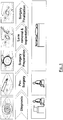
- a first step involves the diagnosis of the eye to be treated.
- the geometry of an eye is determined using a device like an IOL Master from Zeiss. It may further include a topometry measurement to measure the corneal surface of the eye. Moreover, it may include the use of a refractometer to determine the visual performance of the eye. This diagnostic data is used to define the IOL type and IOL geometry that should be implanted.
- a second step consists of the pre-surgery preparation.
- This may include e.g. the marking of the reference vertical and horizontal axes on the eye, typically by a pen.
- a third step consists of the surgery preparation. This involves e.g anesthesia, desinfection and lid speculum in the eye. If the surgery involves a toric IOL, this also involves the marking of the astigmatism axis with marking pen or special axis marker (Mendez Ring) for later final IOL orientation.
- the third step further includes the preparation of incisions for instruments and for implanting the lens. Finally a viscoelastica is injected to the eye to ensure a smooth lens implantation.
- a fourth step includes the actual surgical steps, such as capsulorhexis, hydrodissection, phacoemulsification, and of course then the lens implantation.
- a fifth step of the whole procedure is the surgery finalisation, which may e.g. involve the alignment of the IOL, for toric IOLs the angular positioning of the IOL, and finally the removal of the viscoelastica,
- Fig. 1 The whole procedure is schematically illustrated in Fig. 1 . It should be noted that these steps, especially the pre-surgery preparation and the surgery preparation are carried out by the surgeon manually without any assistance by computerised tools. E.G. the marking of the axis of the eye involves setting marks by a pen on the actual eye, which is a very tedious work for the surgeon. Moreover, the marks may become fuzzy or may disappear over time, which may negatively affect the performance and accuracy of the surgery.
- DE 10 2008 017 111 A1 discloses a system and a method for navigating an object in an imaged subject. There is disclosed to image a subject such as a human body, and to track an object which is navigated through the subject by some tracking technology. The position of the object according to the tracking technology within a navigation coordinate system is made consistent with the position of the object within an imaging coordinate system resulting from the imaging system. For that purpose a corresponding modification of the registration between the two coordinate systems is performed.
- WO 2008/008044 A2 discloses methods and apparatuses for reuse registration data guided surgery.
- One embodiment includes: receiving input data to register image data with a patient; generating registration data based on the input data; and recording the registration data.
- Another embodiment includes: performing a search for registration data for registering image data with a patient in an image guided process; response to a determination to perform registration after the search, receiving input data to register the image data with the patient, generating registration data based on the input data, and recording the registration data; and response to a determination to use the registration data found in the search, using the registration data found in the search in the image guided process.
- a method for image processing for computer-aided eye-surgery of an eye comprising:
- the absolute spatial location of the context information in the newly determined coordinate system of the reference image can be determined. This location can then later be used to accurately place the context information at the same location in the real-time image during surgery.
- the first alternative uses an initial image of the real-time sequence and performed registration between the initial image and the reference image. This leads to a first coordinate transformation. Then there is performed tracking of the real-time images starting with the initial image to obtain a second coordinate transformation. Combining both transformation leads to the transformation which corresponds to the difference between reference image and a real-time image of the sequence.
- the surgery planning data which can be overlaid significantly assists the surgeon to perform the right operation at the right place.
- the overlay of diagnostic information such as wavefront data or topometry data can be of great help during surgery.
- the location were the context information is overlaid on the real-time eye image is the same location as it was added to the reference image.
- the context information overlay over the real-time image can be switched on and off by the surgeon.
- an apparatus for image processing for computer-aided eye-surgery of an eye comprising:
- the location were the context information is overlaid on the real-time eye image is the same location as it was added to the reference image.
- the context information overlay over the real-time image can be switched on and off by the surgeon.
- a computer program comprising computer program code which when being executed on a computer enables said computer to carry out a method according to one of the embodiments of the invention.
- an apparatus which achieves an improvement of the intraocular lens surgery process by linking diagnostic and pre-surgery planning results of a patient's eye directly with the patient's eye under the surgeon's microscope.
- the conventional IOL surgery process starts with a diagnosis of the eye to be treated.
- geometry of an eye is determined using an IOL Master (a medical device, manufactured e.g. by Zeiss). Additionally often the topometry and the refraction of an eye is determined in advance. This diagnostic data is used to define the IOL type and IOL geometry that should be implanted.
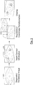
- FIG. 2 the operation of such a device which can assist the surgeon will be explained.
- an image 200 of the eye which can be used for diagnosis and especially is then used as a reference image in the further procedure of the operation.
- the surgeon by means of some graphical manipulation tool or image processing tool can insert context information 210 into the reference image or add context information to the reference image, such as e.g. marking one or more locations or regions in the image.
- context information 210 such as e.g. marking one or more locations or regions in the image.
- the reference image contains this additional information (context information) and may be regarded as having two components, the first component being the actual reference image which has been acquired and a second component being the additional context information (with its location in or with respect to the reference image).
- the schematically illustrated context information 210 can for example be markers which show the surgeon where to make incisions during the surgery.
- the context information is stored and treated separately from the reference image, e.g. as a separate file or dataset. This makes it possible to maintain the original reference image and the context information separately, e.g. if (as will be described later in more detail) only the context information is to be overlaid onto the real-time image during surgery.
- the context information includes information about the location of the context information in the reference image, so that at a later time it will always be possible to "insert" the context information at a later stage in the reference image or in the real-time image during surgery. The latter may then involve additional coordinate transformation based on registration and tracking, as will be explained later in more detail.
- the operation may include the definition of the coordinate system in the reference image.
- a coordinate system determination which uses fixed points or features of the eye which do not change (or do not significantly change) over time, such as the limbus or other eye features like scleral blood vessels.
- an origin of a coordinate system may be defined or determined, either manually or automatically, however, in any case in such a way that the coordinate system can again be determined (or found) at the same position in the eye at a later time. From a comparison of the location of the coordinate system in the reference image and the same coordinate system in the real-time image (or an initial image of a real-time image sequence) one can then determine a coordinate transformation which has to be applied to shift one coordinate system such that it coincides with the other one, as will be explained later in more detail.
- the operation of the apparatus then further proceeds by performing a registration of the diagnostic or reference image 220 with the actual real-time image 215 as taken by a camera from the patient "live".
- the registration process has the effect that there is determined the coordinate transformation which is necessary to "shift” the reference image such that it matches with the actual live image 215 (or a selected actual live image at a certain time) of the patient.
- this overlaid image which contains context information can be "tracked" with the movement of the eye in real time, so that the surgeon then always has on his monitor a real time image of the eye with additional context information overlaid which can assist him with performing (or planning the surgery).
- the two coordinate transformations z1 and z2 together then enable a movement compensation of the eye and allow the context information to be overlaid onto the real-time eye image at a fixed location with respect to the eye, despite the eye's movement.
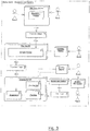
- a diagnostic device (which may be operated by a nurse) includes a diagnostic camera (or reference image camera) which then acquires the diagnostic image or reference image.
- the images are stored and processed in a computer (such as a PC) and the computer then performs a processing which allows the user to perform graphical manipulations or graphical image processing in order to enrich the acquired reference image with context information, in other words to "add" context information to the reference image or to "define” the context information.
- the context information may be any information which assists the surgeon while performing the surgery. In particular this may involve marks which are useful for planning (and then performing) the surgery or it may also involve diagnostic information.
- a "planning monitor” which may comprise a screen or a touch screen on which the physician then can insert (or add or define) context information by a graphical manipulation tool, e.g. by selecting one or more positions or regions in the reference image which should be marked, so that there results then a reference image enriched by context information.
- the surgeon may e.g. just select points or regions, and in this way he may define locations in the eye where the context information is to be displayed.
- the reference image or diagnostic image which is enriched by context information.
- it is a separate dataset or file which includes the context information, the context information including a definition of one or more positions in the eye where the context information is located.
- the context information may further in addition to its location may include the actual context information which may just be a single bit indicating the corresponding position as selected, or it may include more detailed information such as the colour or the style (dashed line or non-dashed line, etc,) in which it should be displayed.
- the thus enriched reference image then is inputted into a processing unit (which may again be a PC, according to one embodiment even the PC which also forms the surgery planner) which performs registration of the reference image with the real time image of the eye (live image) and then also performs a tracking of the live image.
- a processing unit which may again be a PC, according to one embodiment even the PC which also forms the surgery planner
- a processing unit which performs registration of the reference image with the real time image of the eye (live image) and then also performs a tracking of the live image.
- a processing unit which may again be a PC, according to one embodiment even the PC which also forms the surgery planner
- a processing unit which performs registration of the reference image with the real time image of the eye (live image) and then also performs a tracking of the live image.
- the registration may be performed based on the non-enriched reference image, assuming that the context information is stored in a separate file and is then only used later after the registration using the "pure" reference image as been performed.
- This overlay unit may also be implemented by a PC or by a module of the processing unit which performs the registration and tracking.
- the overlay unit performs operation of "overlaying" the context information on the live image of the patient's eye.
- the overlay unit makes reference to the coordinate transformation data which has been obtained by the registration process, and which represents the positional shift which has to be performed so that the reference image matches with the live image.
- This coordinate transformation then is applied to the context information which can then be displayed in the real-time live image of the eye.
- This results in an overlay where the real-time image of the eye has overlaid the additional context information which has been added to the reference image during the step of adding context information.
- an eye tracking mechanism which in principle is known in the art
- the overlay can follow the movement of the eye so that the context information is overlaid always at the same position at which it has been added during the planning phase, despite the movement of the eye.
- the physician can see the live image enriched by the context information which are overlaid on the live image and which follows the movement of the eye so that it always is displayed at the same position of the live image, which in one embodiment is actually the position at which it has been added to the reference image.
- Incisions are placed near the limbus border in the scleral area or even in the cornea. Due to the physical behaviour of the cornea and depending on the position of the incision, astigmatism can be induced to the cornea of up to several diopters. This well known effect is usually used to compensate existing astigmatisms by choosing the right incision position. Inaccurate placement of incisions may lead to additional astigmatism or less compensated astigmatism and therefore a decreased visual outcome for the patient. Incision planning is based on several methods, all mainly based on the topometry of the cornea.
- an intermediate surgery planning step can be introduced, where a doctor is planning - after receiving the diagnostic data and before the surgery - the best fitting incisions for the patient.
- the incisions can be tagged and labelled as visual context information on the diagnostic image.
- registration for IOL surgery the eye coordinate system of the diagnostic image is registered to the eye coordinate system at the surgery.
- tracking for IOL surgery the eye coordinate system during surgery is consistently matched with the diagnostic eye coordinate system. This way the doctor is able to overlay the visual context information added in the surgery planning step on top of the current surgery microscope image.
- the reference image where the context information is added to may be a "pure" image of the eye or may be a diagnostic image which may include additional information such as topometry information.
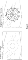
- Fig. 4 schematically illustrates an eye image where there are overlaid incision markers which are regions which have been marked on the reference or diagnostic image during the planning phase and which are now overlaid on the real-time live image of the eye during surgery.
- Fig. 4 What can be seen in Fig. 4 is that not only the incision marks are displayed, but also angular marks from 0 ° to 180 ° for the upper half and from 0° to 180 ° for the lower half. These angular marks have e.g. been fitted to the limbus during the planning of the surgery, and the 0 ° line has been chosen to coincide with the x-axis of the coordinate system in the diagnostic image.
- the coordinate system in the diagnostic image has been chosen such that its origin e.g. coincides with the center of the limbus and its x-axis is parallel with the x-direction of the image.
- the 0 ° line of the angular indication is inclined compared to the x-axis of the coordinate system (the 0 ° line in the coordinate system of the real-time image which again is chosen to be horizontal in the image).
- This is an indication that the eye has rotated compared to the position it had when the context information was defined (when the incision marks were added).
- the angular indication marks (from 0 ° to 180 °) therefore indicate how much the real-time image is inclined (or rotated) compared to the diagnostic or reference image at which the incision marks have been marked during the planning phase.
- the coordinate transformation which transforms the diagnostic image into the real-time image By registration and/or tracking between the reference image and the real-time image there is obtained the coordinate transformation which transforms the diagnostic image into the real-time image, and this coordinate transformation is then applied to the context information (in Fig. 4 the incision marks and also the angular indications) so that the context information is then actually displayed on the correct location in the real-time image.
- the incision marks displayed in the real-time image are displayed at exactly the location where the surgeon has to apply the incisions, despite the movement of the eye. This is due to the coordinate transformation which is applied to the context information before it is overlaid onto the real-time image.
- the context information (the incision marks shown on the right-hand side of Fig. 4 ) are displayed on the correct location, despite the eye movement, and therefore the context information (here: the incision marks) can assist the surgeon performing the surgery in real-time.
- an apparatus for assisting the surgeon with the angular placement of toric IOLs is provided.
- the intermediate surgery planning step can be used to identify the best cylinder axis aligning the toric IOL for the patient's eye.
- the cylinder axis can be tagged and labelled as visual context information on the diagnostic image by selecting the corresponding location or locations in the diagnostic or reference image.
- a graphical user interface which enables the surgeon to select or input the context information, e.g. through the mouse or the keyboard, our by means of a touch screen.
- the eye coordinate system of the diagnostic image is registered to eye coordinate system at the surgery.
- tracking for IOL surgery the eye coordinate system during surgery is consistently matched with the diagnostic eye coordinate system.
- the surgeon is able to overlay the visual context information added in the surgery planning step on top of the current surgery microscope image. All manual, ink based steps for transforming the coordinate system become obsolete in this embodiment, and the usage of toric IOLs therefore becomes much easier for the surgeon.
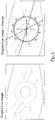
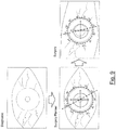
- Fig. 5 schematically illustrates an eye image where there is overlaid the 0° line of the diagnostic image (the dotted line). Also shown is the 0° line of the actual live image (the full x-axis) and the orientation for the toric lens (the dashed line). From comparison with the reference coordinate system (a comparison between the x-axis in the real-time image and the dotted line which is the 0° line in the diagnostic image) the surgeon can identify how much the real-time image has been inclined compared to the diagnostic image.
- the dashed line From the dashed line he can identify the direction along which the toric lens has to be aligned, because similarly to the previous embodiment the dashed line due to the application of a coordinate transformation which is obtained from registration and/or tracking between the reference image and the real-time image the dashed line is displayed on a location which compensates for a movement of the real-time image compared with the reference image.
- the reason that the two lines (the diagnostic 0° line and the 0° line of the real-time image) do not match each other in this embodiment is that there has been some movement of the eye from the reference image to he real-time image during surgery. This is reflected by the inclination between the 0° line of the reference image (shown as dotted line) and the x-axis of the real-time image (shown as full line and as x-axis of the coordinate system in the real-time image).
- the eye would not have moved at all and would be located at exactly the same location and exactly aligned in the same way as it was when the reference image was taken, then the dotted line (0° line of the reference image) and the x-axis of the real-time image would coincide.
- the coordinate system which was initially defined in the reference image (based on one or more features or landmarks of the eye) is now shifted and possibly also rotated, and therefore diagnostic 0° line and the 0° line of the real-time image typically do not coincide anymore, as can be seen from Fig. 5 .
- Fig. 5 there is shown the 0° line which can be automatically determined in the reference image and also in the real-time image, e.g. by using the limbus and other eye features.
- the limbus may e.g. be fitted by a circle and then the center may be used as the origin of the coordinate system.
- Any other feature e.g. a blood vessel may be used as a reference to determine the direction of the x- and y- axis, where the actual direction of these axis is not so important as long as the determination algorithm for the coordinate system is unambiguously determining the location of the coordinate system so that the coordinate system in the reference image and the real-time image is located at the same position in the eye.
- the x-axis of the coordinate system may be highlighted as the 0° axis (as shown in Fig. 5 as dotted line), and additionally there can then be displayed overlaid the alignment-axis (shwon as dashed line in Fig. 5 ) along which the toric IOL should be aligned.
- This latter axis has been determined by the surgeon using a graphical user interface (e.g. by the mouse) during the surgery planning phase when he added the context data to the reference image.
- the 0° line (the dotted line) and the alignment axis (the dashed line) are displayed in the real-time image based on a coordinate transformation which is obtained from registration and/or tracking between the reference image (where the ° line and the alignment axis have been defined) and the real-time image.
- a coordinate transformation which is obtained from registration and/or tracking between the reference image (where the ° line and the alignment axis have been defined) and the real-time image.
- an apparatus for assisting the surgeon with the lateral and angular placement of phakic IOLs is provided.
- Phakic IOLs are placed in front of the iris of a patient's eye and are anchored with dedicated fixation elements or haptics to the iris.
- the existing human eye lens remains in the eye to work together with the newly inserted Phakic IOLs to allow accommodation for near and far vision. Because there are multifocal, toric or multifocal-toric Phakic IOLs available, the lateral and toric placement of this Phakic IOLs is of special interest.
- the intermediate surgery planning step can be used to identify the exact position of the Phakic IOL for the patient's eye taking into account translations and rotation of the Phakic IOL, and taking into account the limbus position, the photopic pupil, the scotopic pupil, and the line of sight. Knowing the final position of the Phakic IOL the anchor areas for the haptics can be planned as well.
- All of the above-mentioned information can be tagged and labelled as visual context information on the diagnostic image.
- the photopic pupil and the scotopic pupil may e.g. be measured in the diagnostic image.
- the eye coordinate system of the diagnostic image is registered to eye coordinate system at the surgery, and then the context information such as photopic and scotopic pupil can be overlaid on the real-time image using the coordinate transformation determined by the registration.
- the eye coordinate system during surgery is consistently matched with the diagnostic eye coordinate system. This way the doctor is able to overlay the visual context information added in the surgery planning step on top of the current surgery microscope image.
- Fig. 6 is a figure where as a context information the pupil as determined for example as an average of the photopic and scotopic pupil during the diagnostic/planning phase is indicated as overlay in the real-time image. This information helps the surgeon during the phakic IOL surgery.
- a standard pupil can be derived e.g. from the photopic and scotopic pupil and linked to the diagnostic image in the surgery planning step and can be overlaid on the real-time image.
- Fig. 7 is a figure where as a context information the line of sight (which also may have been determined during the planning or diagnostic phase) is overlaid on the real-time image.
- the same planning, registration and tracking technique can be applied for related surgery areas, where positioning and rotation of implants is significant for clinical outcome.
- Examples would be corneal inlays or corneal onlays.
- an apparatus for assisting the surgeon by overlaying diagnostic data such as corneal topometry data or the wavefront data is provided.
- topometry data is usually determined from a single image or single perspective of a diagnostic device.
- One assumption is that the patient is fixating to the center of the diagnostic device, which is in practice not always the case.
- 6D registration from diagnostic to surgery, however, the fixation of the patient is no longer relevant.
- the former position of the eye in all six degrees of freedom can be determined and the topometry data of the cornea can be visualised during surgery as an online re-computed topometry of the cornea depending on the 6D position of the eye under the microscope.
- the corneal topometry or wavefront data is acquired.
- This data which has been acquired during the diagnostic step in its 6-dimensional spatial relationship to the 6-dimensional eye image can then be stored and after registration and by using tracking it can be overlaid over the real-time image of the eye during surgery. This is done by re-computing the position of the 6-dimensional diagnostic information (wavefront or topometry data) based on the coordinate transformation obtained form registration and tracking. Then this diagnostic data (wavefront or topometry data) can be displayed by overlaying it onto the real-time image of the eye during surgery.
- Fig. 8 exemplarily illustrates the overlay of such data as topometry data or wavefront data.
- this approach has significant advantages.
- One main advantage of this method is that the cornea is not measured during surgery on a physically manipulated eye, but during diagnosis on a relaxed eye. This way the visualised information during surgery is independent from the surgery conditions of the eye, and the overlaid information is the "real" diagnostic information without the distorting effect which is caused by the physical manipulation of the eye during surgery.
- the doctor uses a diagnostic device (e.g. a topometer or IOL-master) to determine the parameters required for later IOL surgery.
- the device must be capable to acquire images of the eye with sufficient pixel resolution and visible illumination (e.g., white or green) to allow registration and tracking for IOL surgery.
- This "Diagnostic Image” will be used as a reference image defining the original coordinate system for the diagnostic data and all following process steps.
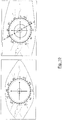
- Fig. 9 the upper part schematically illustrates such a diagnostic image or reference image.
- the diagnostic step may further involve the acquisition of topometry data or wavefront data, as was explained before.
- the surgery planning step is an intermediate step between diagnosis and surgery that allows the doctor to plan its future actions in the surgery.
- On the Diagnostic Image the limbus and eye features outside the limbus are measured, to define the original coordinate system.
- Different type of context information e.g. incisions, cylinder axis, line of sight, etc.
- the software may include a helping function which supports the doctor in finding the right incisions, cylinder axis or other relevant parameters, by executing some algorithms which are able to calculate relevant positions for surgery planning using existing literature data.
- the lower left part illustrates exemplarily the planning with the insertion (or definition) of a standard pupil (the dotted circle) and the definition of a cylinder axis (the dashed line, e.g. for aligning toric lenses).
- the doctor can do the planning step independent of the presence of the patient and with no time pressure e.g. due to fading ink markers.
- Multiple patient sessions can be planned sequentially due to the fixed coordinate system which can be recalculated and reused in later sessions, as it is also then later used during surgery.
- the output data of the Surgery Planner software (Planning Content) of a patient may be transferred to the surgery environment using network or memory stick devices.
- the planning step is performed at the same computer as the surgery registration and tracking, then no such transfer is necessary.
- the registration and tracking processing unit acquire and process online eye images from the microscope camera (surgery mages).
- a (touch screen) monitor near the surgeons chair or a monitor in the microscope then displays the surgery images online (real-time).
- interactions with the processing unit which carries out the tracking and overlay processing are possible via a touch screen monitor or a foot paddle, e.g. to switch the overlay information on or off.
- the Planning Content (context information) of the current patient is be loaded to the processing unit that is linked to the microscope camera, and through registration and tracking it can be overlaid on the real-time image during surgery.
- the doctor activates the registration from the Diagnostic Image to the Surgery Image to determine the absolute coordinate transformation from diagnostic to surgery (Diagnostic Transformation).
- the selected Surgery Image where the registration to the Diagnostic Image is successful, will be stored as Surgery Reference image.
- the doctor can activate the overlay functionality every time he or she wants to visualize the Planning Content (the context information). This is achieved by tracking the eye under surgery conditions, where for each tracking period P the Diagnostic Transformation (which is the transformation from the diagnostic image to the surgery reference image) and the coordinate transformation from the current Surgery Image to the first Surgery Image of P is added. In this way the context information is displayed always at the same location in the real-time image of the eye, despite the movement of the eye.
- the Diagnostic Transformation which is the transformation from the diagnostic image to the surgery reference image
- the coordinate transformation from the current Surgery Image to the first Surgery Image of P is added.
- Fig. 9 the overlay is shown on the lower right-hand side. From the displacement of the 0° line with the 0° line of the real-time image one can see that in this example the eye does not completely match the orientation of the eye at the diagnostic or reference phase. There is some rotational displacement between the diagnostic image and the real-time image which is visualized by the 0° line as indicated by the angular indications is inclined compared to the x-axis of the image itself.
- Fig. 10 shows in somewhat more detail the actual surgery planning step.
- the coordinate system in the reference image e.g. such that the origin matches with the center of the limbus and that the x-axis is parallel to the x-direction of the image itself.
- an angular indication where a circle fitted to the limbus id divided in an upper half marked with angles from 0 ° to 180° and a lower half marked with angles from 0° to 180 °.
- the context data here exemplarily an axis (dashed line) and a standard pupil (dotted circle) are added.
- Other context information such as incision marks could be added in a similar manner.
- context information like incision markers or the alignment axis the whole operation can be performed using only 2-dimensional images.
- information such information as topometry data or wavefront data are to be used as context information there is preferably used a 6-dimensional registration and tracking process, as explained before.
- the whole apparatus can be relatively easily integrated into existing surgery microscopes by adding a camera which takes digital images and a processing unit which allows the acquisition of the diagnostic or reference image, the addition of context information, and the use of the context information for overlaying it onto the real-time image based on registration and tracking.
- a computer program either stored in a data carrier or in some other way embodied by some physical means such as a recording medium or a transmission link which when being executed on a computer enables the computer to operate in accordance with the embodiments of the invention described hereinbefore.
Claims (11)
- Verfahren zur Bildverarbeitung für die computerunterstützte Augenchirurgie, wobei das Verfahren umfasst:Aufnehmen eines Referenzbilds des Auges;Aufwerten des Referenzbilds durch Einfügen zusätzlicher Kontextinformation, die für einen Chirurgen bei der Durchführung der Augenchirurgie hilfreich ist;Ausrichten des Referenzbilds gegenüber einer Echtzeitaufnahme des Auges; undÜberlagern der Kontextinformation auf das Echtzeitbild des Auges auf der Grundlage von Verfolgung der Augenbewegung, so dass die Kontextinformation trotz einer Bewegung des Auges an der gleichen Stelle angezeigt wird;wobei der Ort, an dem die Kontextinformation dem Echtzeit-Augenbild überlagert wird, der gleiche Ort ist, an dem sie zu dem Referenzbild hinzugefügt worden ist, und wobei die Kontextinformation eines oder mehrere der folgenden ist:diagnostische Daten, die Eigenschaften oder Parameter des Auges darstellen, die für diagnostische Zwecke von Nutzen sind;Chirurgieplanungsdaten, die eine oder mehrere Richtungen, in denen der Chirurg einen bestimmten chirurgischen Vorgang durchführen sollte, graphisch anzeigen;Implantatplatzierungsdaten, die einen oder mehrere Orte, wo, und/oder Ausrichtungen oder Richtungen, in denen ein Implantat, z. B. eine IOL, auf oder in das Auge gesetzt werden soll, graphisch anzeigen.
- Verfahren gemäß Anspruch 1, ferner umfassend:Bestimmen eines ersten Koordinatensystems unter Verwendung eines Koordinatensystem-Bestimmungsalgorithmus auf der Grundlage eines oder mehrerer Merkmale des Auges in dem Referenzbild;Bestimmen des räumlichen Orts der Kontextinformation auf der Grundlage des Koordinatensystems;Bestimmen eines zweiten Koordinatensystems in dem während des chirurgischen Eingriffs aufgenommenen Echtzeitbild unter Verwendung des Koordinatensystem-Bestimmungsalgorithmus;Bestimmen des Orts, an dem die Kontextinformation zu überlagern ist, durch Bestimmen der Koordinatentransformation von dem ersten Koordinatensystem zu dem zweiten Koordinatensystem.
- Verfahren gemäß Anspruch 1 oder 2, umfassend:Ausrichten des Referenzbilds gegenüber einem Anfangsbild einer Echtzeit-Bildsequenz, um eine Anfangs-Koordinatentransformation zu erhalten;Verfolgen der Augenbewegung auf der Grundlage eines Vergleichs der weiteren Echtzeitbilder im Vergleich zu dem Anfangsbild einer Echtzeit-Bildsequenz, um eine zweite Koordinatentransformation zu erhalten, und Erhalten einer abschließenden Koordinatentransformation von dem Referenzbild zu einem Echtzeitbild der Echtzeit-Bildsequenz auf der Grundlage einer Kombination der ersten und der zweiten Koordinatentransformation, um eine Anzeige der Kontextinformation in dem Echtzeitbild auf der Grundlage der kombinierten Koordinatentransformation zu ermöglichen; oderAusrichten des Referenzbilds gegenüber den Echtzeitbildern einer Echtzeit-Bildsequenz, um eine Koordinatentransformation von dem Referenzbild zu dem Echtzeitbild der Echtzeit-Bildsequenz zu erhalten, um eine Anzeige der Kontextinformation in dem Echtzeitbild auf der Grundlage der erhaltenen Koordinatentransformation zu ermöglichen.
- Verfahren gemäß einem der vorstehenden Ansprüche, wobei
die Überlagerung der Kontextinformation auf das Echtzeitbild von dem Chirurgen ein- und ausgeschaltet werden kann. - Verfahren gemäß einem der vorstehenden Ansprüche, wobei die Kontextinformation eines oder mehrere der folgenden ist:eine oder mehrere Einschnittmarkierungen zum Markieren des Orts, an dem ein Einschnitt durchgeführt worden ist;eine Zylinderachse zum Platzieren einer torischen Intraokularlinse;ein oder mehrere Ankerbereiche zum Verankern einer Vorrichtung;eine Pupillenmarkierung oder eine Sichtlinienmarkierung;topometrische Daten oder Wellenfrontdaten des Auges;die Position von Hornhaut-Inlays oder Hornhaut-Onlays.
- Vorrichtung zur Bildverarbeitung zur computerunterstützten Augenchirurgie, wobei die Vorrichtung umfasst:ein Modul zum Aufnehmen eines Referenzbilds des Auges;ein Modul zum Aufwerten des Referenzbilds durch Einfügen zusätzlicher Kontextinformation, die für einen Chirurgen bei der Durchführung der Augenchirurgie hilfreich ist;ein Modul zum Ausrichten des Referenzbilds gegenüber einer Echtzeitaufnahme des Auges; undein Modul zum Überlagern der Kontextinformation auf das Echtzeitbild des Auges auf der Grundlage von Verfolgung der Augenbewegung, so dass die Kontextinformation trotz einer Bewegung des Auges an der gleichen Stelle angezeigt wird;wobei der Ort, an dem die Kontextinformation dem Echtzeit-Augenbild überlagert wird, der gleiche Ort ist, an dem sie zu dem Referenzbild hinzugefügt worden ist, und wobei die Kontextinformation eines oder mehrere der folgenden ist:diagnostische Daten, die Eigenschaften oder Parameter des Auges darstellen, die für diagnostische Zwecke von Nutzen sind;Chirurgieplanungsdaten, die eine oder mehrere Richtungen, in denen der Chirurg einen bestimmten chirurgischen Vorgang durchführen sollte, graphisch anzeigen;Implantatplatzierungsdaten, die einen oder mehrere Orte, wo, und/oder Ausrichtungen oder Richtungen, in denen ein Implantat, z. B. eine IOL, auf oder in das Auge gesetzt werden soll, graphisch anzeigen.
- Vorrichtung gemäß Anspruch 6, ferner umfassend.
ein Modul zum Bestimmen eines ersten Koordinatensystems unter Verwendung eines Koordinatensystem-Bestimmungsalgorithmus auf der Grundlage eines oder mehrerer Merkmale des Auges in dem Referenzbild;
ein Modul zum Bestimmen des räumlichen Orts der Kontextinformation auf der Grundlage des Koordinatensystems;
ein Modul zum Bestimmen eines zweiten Koordinatensystems in dem während des chirurgischen Eingriffs aufgenommenen Echtzeitbild unter Verwendung des Koordinatensystem-Bestimmungsalgorithmus;
ein Modul zum Bestimmen des Orts, an dem die Kontextinformation zu überlagern ist, durch Bestimmen der Koordinatentransformation von dem ersten Koordinatensystem zu dem zweiten Koordinatensystem. - Vorrichtung gemäß Anspruch 6 oder 7, ferner umfassend:ein Modul zum Ausrichten des Referenzbilds gegenüber einem Anfangsbild einer Echtzeit-Bildsequenz, um eine Anfangs-Koordinatentransformation zu erhalten, undein Modul zum Verfolgen der Augenbewegung auf der Grundlage eines Vergleichs der weiteren Echtzeitbilder im Vergleich zu dem Anfangsbild einer Echtzeit-Bildsequenz, um eine zweite Koordinatentransformation zu erhalten, und Erhalten einer abschließenden Koordinatentransformation von dem Referenzbild zu einem Echtzeitbild der Echtzeit-Bildsequenz auf der Grundlage einer Kombination der ersten und der zweiten Koordinatentransformation, um eine Anzeige der Kontextinformation in dem Echtzeitbild auf der Grundlage der kombinierten Koordinatentransformation zu ermöglichen; oderein Modul zum Ausrichten des Referenzbilds gegenüber den Echtzeitbildern einer Echtzeit-Bildsequenz, um eine Koordinatentransformation von dem Referenzbild zu dem Echtzeitbild der Echtzeit-Bildsequenz zu erhalten, um eine Anzeige der Kontextinformation in dem Echtzeitbild auf der Grundlage der erhaltenen Koordinatentransformation zu ermöglichen.
- Vorrichtung gemäß einem der Ansprüche 6 bis 8, wobei
die Überlagerung der Kontextinformation auf das Echtzeitbild von dem Chirurgen ein- und ausgeschaltet werden kann. - Vorrichtung gemäß einem der Ansprüche 6 bis 9, wobei die Kontextinformation eines oder mehrere der folgenden ist:eine oder mehrere Einschnittmarkierungen zum Markieren des Orts, an dem ein Einschnitt durchgeführt worden ist;eine Zylinderachse zum Platzieren einer torischen Intraokularlinse;ein oder mehrere Ankerbereiche zum Verankern einer Vorrichtung;eine Pupillenmarkierung oder eine Sichtlinienmarkierung zum Platzieren einer phakischen Intraokularlinse an der richtigen Position;topometrische Daten oder Wellenfrontdaten des Auges;die Position von Hornhaut-Inlays oder Hornhaut-Onlays.
- Computerprogramm, umfassend einen Computerprogrammcode, der bei Ausführung auf einem Computer dem Computer ermöglicht, ein Verfahren gemäß einem der Ansprüche 1 bis 5 auszuführen.
Priority Applications (2)
| Application Number | Priority Date | Filing Date | Title |
|---|---|---|---|
| EP09737424.3A EP2373207B1 (de) | 2008-10-22 | 2009-10-20 | Verfahren und vorrichtung zur bildverarbeitung für computerunterstützte augenoperationen |
| PL09737424T PL2373207T3 (pl) | 2008-10-22 | 2009-10-20 | Sposób i urządzenie do przetwarzania obrazów dla komputerowo wspomaganej operacji wzroku |
Applications Claiming Priority (3)
| Application Number | Priority Date | Filing Date | Title |
|---|---|---|---|
| EP08167232A EP2184005B1 (de) | 2008-10-22 | 2008-10-22 | Verfahren und Vorrichtung zur Bildverarbeitung für computerunterstützte Augenoperationen |
| EP09737424.3A EP2373207B1 (de) | 2008-10-22 | 2009-10-20 | Verfahren und vorrichtung zur bildverarbeitung für computerunterstützte augenoperationen |
| PCT/EP2009/063753 WO2010046371A1 (en) | 2008-10-22 | 2009-10-20 | Method and apparatus for image processing for computer-aided eye surgery |
Publications (2)
| Publication Number | Publication Date |
|---|---|
| EP2373207A1 EP2373207A1 (de) | 2011-10-12 |
| EP2373207B1 true EP2373207B1 (de) | 2019-09-11 |
Family
ID=40469903
Family Applications (2)
| Application Number | Title | Priority Date | Filing Date |
|---|---|---|---|
| EP08167232A Active EP2184005B1 (de) | 2008-10-22 | 2008-10-22 | Verfahren und Vorrichtung zur Bildverarbeitung für computerunterstützte Augenoperationen |
| EP09737424.3A Active EP2373207B1 (de) | 2008-10-22 | 2009-10-20 | Verfahren und vorrichtung zur bildverarbeitung für computerunterstützte augenoperationen |
Family Applications Before (1)
| Application Number | Title | Priority Date | Filing Date |
|---|---|---|---|
| EP08167232A Active EP2184005B1 (de) | 2008-10-22 | 2008-10-22 | Verfahren und Vorrichtung zur Bildverarbeitung für computerunterstützte Augenoperationen |
Country Status (11)
| Country | Link |
|---|---|
| US (1) | US8903145B2 (de) |
| EP (2) | EP2184005B1 (de) |
| JP (1) | JP5579725B2 (de) |
| CN (1) | CN102264280B (de) |
| AT (1) | ATE509568T1 (de) |
| BR (1) | BRPI0919756A2 (de) |
| DK (1) | DK2373207T3 (de) |
| ES (1) | ES2750334T3 (de) |
| PL (1) | PL2373207T3 (de) |
| PT (1) | PT2373207T (de) |
| WO (1) | WO2010046371A1 (de) |
Families Citing this family (47)
| Publication number | Priority date | Publication date | Assignee | Title |
|---|---|---|---|---|
| US8820929B2 (en) * | 2006-01-20 | 2014-09-02 | Clarity Medical Systems, Inc. | Real-time measurement/display/record/playback of wavefront data for use in vision correction procedures |
| JP5511516B2 (ja) * | 2010-05-31 | 2014-06-04 | 株式会社ニデック | 眼科装置 |
| JP5818409B2 (ja) * | 2010-06-17 | 2015-11-18 | キヤノン株式会社 | 眼底撮像装置及びその制御方法 |
| US20120022408A1 (en) * | 2010-06-18 | 2012-01-26 | Vantage Surgical Systems, Inc. | Surgical Procedures Using Visual Images Overlaid with Visual Representations of Selected Three-Dimensional Data |
| PT2621329T (pt) * | 2010-09-30 | 2017-05-25 | Wavelight Gmbh | Disposição para assistência a um tratamento cirúrgico de olho |
| US8740382B1 (en) * | 2010-09-30 | 2014-06-03 | Cognex Corporation | System and method for automatically tracking a contact lens in a wearer's eye |
| US8231221B2 (en) | 2010-09-30 | 2012-07-31 | Wavelight Gmbh | Arrangement and method for carrying out a surgical treatment of an eye |
| ES2959110T3 (es) * | 2010-11-26 | 2024-02-20 | Alcon Inc | Aparato para el registro ocular multinivel |
| EP2583619B1 (de) * | 2011-10-22 | 2022-03-16 | Alcon Inc. | Vorrichtung zur Überwachung eines oder mehrerer Augenparameter |
| PT2583618T (pt) * | 2011-10-22 | 2018-01-24 | Alcon Pharmaceuticals Ltd | Aparelho para monitorizar um ou mais parâmetros do olho |
| KR101711358B1 (ko) * | 2012-05-02 | 2017-02-28 | 엠파이어 테크놀로지 디벨롭먼트 엘엘씨 | 의학적 애플리케이션들에서 증강 현실을 위한 동적 모델을 이용한 4 차원 이미지 등록 |
| ES2529321T3 (es) * | 2012-07-06 | 2015-02-19 | Neoptics Ag | Sistema para la inserción de una lente intracorneal |
| WO2014013438A1 (en) * | 2012-07-16 | 2014-01-23 | Lumenis Ltd. | System for laser application |
| EP2908715A4 (de) * | 2012-07-31 | 2016-08-17 | Tracey Technologies Corp | Tps-werkzeuge und verfahren zum chirurgischen einsatz von intraokularimplantaten |
| EP2958035A4 (de) | 2013-02-06 | 2016-10-19 | Hoya Corp | Simulationssystem, simulationsvorrichtung und verfahren zur unterstützung einer produktbeschreibung |
| DE102013002293A1 (de) * | 2013-02-08 | 2014-08-14 | Carl Zeiss Meditec Ag | Augenchirurgiesysteme und Verfahren zum Einsetzen von Introkularlinsen |
| CN103431941B (zh) * | 2013-05-27 | 2015-02-04 | 宋艳萍 | 一种眼科激光治疗设备的黄斑回避控制方法及控制系统 |
| DE102013210728A1 (de) | 2013-06-10 | 2014-12-11 | Carl Zeiss Meditec Ag | Operationsmikroskopiesystem sowie Verfahren zu dessen Betrieb |
| US9968295B2 (en) * | 2013-08-07 | 2018-05-15 | Novartis Ag | Surgical guidance and planning software for astigmatism treatment |
| US10073515B2 (en) | 2013-09-18 | 2018-09-11 | Nanophthalmos, Llc | Surgical navigation system and method |
| US9597009B2 (en) * | 2013-12-19 | 2017-03-21 | Novartis Ag | Marker-based tool tracking |
| JP5570673B2 (ja) * | 2014-03-10 | 2014-08-13 | 株式会社ニデック | 眼科装置 |
| WO2015138988A1 (en) | 2014-03-13 | 2015-09-17 | Richard Awdeh | A microscope insert |
| US20170164829A1 (en) * | 2014-03-13 | 2017-06-15 | Nanophthalmos, Llc | Registration Using a Microscope Insert |
| DE102014106993A1 (de) | 2014-05-19 | 2015-11-19 | Chronos Vision Gmbh | Verfahren und Vorrichtung zur Bestimmung der Ausrichtung des Auges bei Augenoperationen |
| CA2964897A1 (en) | 2014-10-17 | 2016-04-21 | Optimedica Corporation | Laser eye surgery lens fragmentation |
| KR20160071889A (ko) * | 2014-12-12 | 2016-06-22 | 삼성전자주식회사 | 비교 영상을 이용한 진단 지원 장치 및 방법 |
| JP2016112358A (ja) * | 2014-12-18 | 2016-06-23 | ソニー株式会社 | 情報処理装置、手術顕微鏡システム及び情報処理方法 |
| EP3267892A4 (de) * | 2015-03-13 | 2019-01-23 | Richard Awdeh | Verfahren und systeme zur registrierung mit einem mikroskopeinsatz |
| JP6786903B2 (ja) * | 2015-07-31 | 2020-11-18 | 株式会社ニデック | 眼内レンズ挿入システム、眼内レンズ挿入デバイスを制御するための制御装置 |
| US20170083666A1 (en) * | 2015-09-22 | 2017-03-23 | Novartis Ag | Presurgical planning for use during surgical procedure |
| EP3216431B1 (de) * | 2015-10-15 | 2022-06-29 | Sony Group Corporation | Bildverarbeitungsvorrichtung und chirurgisches mikroskop |
| US10820794B2 (en) * | 2015-11-06 | 2020-11-03 | Canon Kabushiki Kaisha | Pupil monitoring method for adaptive optics imaging system |
| JP6880606B2 (ja) * | 2016-08-30 | 2021-06-02 | 株式会社ニデック | 眼科用手術顕微鏡 |
| US10973585B2 (en) | 2016-09-21 | 2021-04-13 | Alcon Inc. | Systems and methods for tracking the orientation of surgical tools |
| DE102016011759B4 (de) | 2016-09-30 | 2022-01-27 | Chronos Vision Gmbh | Vorrichtung und Verfahren zur Anzeige der Astigmatismusachse des Auges |
| DE102017209425A1 (de) | 2017-06-02 | 2018-12-06 | Carl Zeiss Meditec Ag | Augenchirurgiesystem und Verfahren zur Vorbereitung von Eingriffen im Rahmen von Augenoperationen |
| DE102017217375A1 (de) | 2017-09-29 | 2019-04-04 | Carl Zeiss Meditec Ag | Vorrichtung zur Einspiegelung von Parameter und/oder Bilddaten in den stereoskopischen Beobachtungsstrahlengang ophthalmologischer Geräte |
| US10970813B2 (en) * | 2018-07-02 | 2021-04-06 | Alcon Inc. | Shaking image for registration verification |
| US20210267799A1 (en) * | 2020-02-21 | 2021-09-02 | Daniel R. Neal | System and Methods for Customizing an Intraocular Lens Using a Wavefront Aberrometer |
| WO2022163189A1 (ja) * | 2021-01-29 | 2022-08-04 | ソニーグループ株式会社 | 画像処理装置、画像処理方法及び手術顕微鏡システム |
| WO2022163188A1 (ja) * | 2021-01-29 | 2022-08-04 | ソニーグループ株式会社 | 画像処理装置、画像処理方法及び手術顕微鏡システム |
| JP2022116559A (ja) * | 2021-01-29 | 2022-08-10 | ソニーグループ株式会社 | 画像処理装置、画像処理方法及び手術顕微鏡システム |
| CN112836747A (zh) * | 2021-02-02 | 2021-05-25 | 首都师范大学 | 眼动数据的离群处理方法及装置、计算机设备、存储介质 |
| WO2022181194A1 (ja) * | 2021-02-26 | 2022-09-01 | ソニーグループ株式会社 | 画像処理装置、画像処理方法及び手術顕微鏡システム |
| WO2023047626A1 (ja) * | 2021-09-21 | 2023-03-30 | ソニーグループ株式会社 | 画像処理装置、画像処理方法及び手術顕微鏡システム |
| CN114642502B (zh) * | 2022-02-21 | 2023-07-14 | 北京工业大学 | 斜视手术方案的辅助设计方法及装置 |
Citations (9)
| Publication number | Priority date | Publication date | Assignee | Title |
|---|---|---|---|---|
| DE19950791A1 (de) | 1999-10-21 | 2001-05-10 | Technolas Gmbh | Iriserkennung und -nachführung zum Behandeln optischer Ungleichmäßigkeiten des Auges |
| WO2001089373A2 (en) | 2000-05-20 | 2001-11-29 | Sensomotoric Instruments Gmbh | Method and apparatus for measuring ocular alignment |
| US20030223037A1 (en) | 2002-05-30 | 2003-12-04 | Visx, Incorporated | Methods and systems for tracking a torsional orientation and position of an eye |
| US20050025365A1 (en) | 2003-06-06 | 2005-02-03 | Fuji Photo Film Co., Ltd. | Method and apparatus for aiding image interpretation and computer-readable recording medium storing program therefor |
| US20050117118A1 (en) | 2001-10-05 | 2005-06-02 | David Miller | Digital ophthalmic workstation |
| DE102004055683A1 (de) | 2004-10-26 | 2006-05-04 | Carl Zeiss Surgical Gmbh | Augenchirurgie-Mikroskopiesystem und Verfahren hierzu |
| WO2006060323A1 (en) * | 2004-11-30 | 2006-06-08 | Alcon Refractivehorizons, Inc. | Eye registration system for refractive surgery and associated methods |
| WO2008008044A2 (en) | 2006-07-14 | 2008-01-17 | Bracco Imaging S.P.A. | Methods and apparatuses for registration in image guided surgery |
| DE102008017111A1 (de) | 2007-04-03 | 2008-10-09 | General Electric Co. | System und Verfahren zur Navigation eines Ojektes in einem abgebildeten Subjekt |
Family Cites Families (12)
| Publication number | Priority date | Publication date | Assignee | Title |
|---|---|---|---|---|
| JP2853783B2 (ja) | 1990-10-26 | 1999-02-03 | キヤノン株式会社 | 画像透光性透明フィルムおよびそれを用いた画像形成方法 |
| JPH04256342A (ja) | 1991-02-08 | 1992-09-11 | Toshiba Corp | 半導体パッケージ |
| JP3036182B2 (ja) | 1991-10-31 | 2000-04-24 | ソニー株式会社 | 画像符号化装置 |
| ES2199095T3 (es) * | 1999-10-21 | 2007-03-16 | Technolas Gmbh Ophthalmologische Systeme | Reconocimiento y seguimiento del iris para el tratamiento optico. |
| JP4471661B2 (ja) * | 2002-02-11 | 2010-06-02 | ヴィズイクス・インコーポレーテッド | 相対的位置と回転のオフセットの判定 |
| AU2005234778B2 (en) | 2004-04-20 | 2011-04-21 | Alcon Inc. | Integrated surgical microscope and wavefront sensor |
| US7934833B2 (en) * | 2005-12-22 | 2011-05-03 | Alcon Refractivehorizons, Inc. | Image alignment system for use in laser ablation treatment of the cornea |
| DE102006002001B4 (de) | 2006-01-16 | 2009-07-23 | Sensomotoric Instruments Gmbh | Verfahren zur Bestimmung der räumlichen Relation eines Auges einer Person bezüglich einer Kameravorrichtung |
| US8363783B2 (en) * | 2007-06-04 | 2013-01-29 | Oraya Therapeutics, Inc. | Method and device for ocular alignment and coupling of ocular structures |
| US20080312675A1 (en) * | 2007-06-18 | 2008-12-18 | Advanced Medical Optics, Inc. | System and method for calculating limbal relaxing incisions |
| US8369930B2 (en) * | 2009-06-16 | 2013-02-05 | MRI Interventions, Inc. | MRI-guided devices and MRI-guided interventional systems that can track and generate dynamic visualizations of the devices in near real time |
| WO2011091326A1 (en) * | 2010-01-22 | 2011-07-28 | Optimedica Corporation | Apparatus for automated placement of scanned laser capsulorhexis incisions |
-
2008
- 2008-10-22 EP EP08167232A patent/EP2184005B1/de active Active
- 2008-10-22 AT AT08167232T patent/ATE509568T1/de not_active IP Right Cessation
-
2009
- 2009-10-20 PT PT97374243T patent/PT2373207T/pt unknown
- 2009-10-20 US US13/125,682 patent/US8903145B2/en active Active
- 2009-10-20 PL PL09737424T patent/PL2373207T3/pl unknown
- 2009-10-20 ES ES09737424T patent/ES2750334T3/es active Active
- 2009-10-20 CN CN200980151988.9A patent/CN102264280B/zh active Active
- 2009-10-20 EP EP09737424.3A patent/EP2373207B1/de active Active
- 2009-10-20 JP JP2011532614A patent/JP5579725B2/ja active Active
- 2009-10-20 BR BRPI0919756A patent/BRPI0919756A2/pt active Search and Examination
- 2009-10-20 WO PCT/EP2009/063753 patent/WO2010046371A1/en active Application Filing
- 2009-10-20 DK DK09737424.3T patent/DK2373207T3/da active
Patent Citations (10)
| Publication number | Priority date | Publication date | Assignee | Title |
|---|---|---|---|---|
| DE19950791A1 (de) | 1999-10-21 | 2001-05-10 | Technolas Gmbh | Iriserkennung und -nachführung zum Behandeln optischer Ungleichmäßigkeiten des Auges |
| WO2001089373A2 (en) | 2000-05-20 | 2001-11-29 | Sensomotoric Instruments Gmbh | Method and apparatus for measuring ocular alignment |
| US20050117118A1 (en) | 2001-10-05 | 2005-06-02 | David Miller | Digital ophthalmic workstation |
| US20030223037A1 (en) | 2002-05-30 | 2003-12-04 | Visx, Incorporated | Methods and systems for tracking a torsional orientation and position of an eye |
| US20050025365A1 (en) | 2003-06-06 | 2005-02-03 | Fuji Photo Film Co., Ltd. | Method and apparatus for aiding image interpretation and computer-readable recording medium storing program therefor |
| DE102004055683A1 (de) | 2004-10-26 | 2006-05-04 | Carl Zeiss Surgical Gmbh | Augenchirurgie-Mikroskopiesystem und Verfahren hierzu |
| US20060247659A1 (en) * | 2004-10-26 | 2006-11-02 | Carl Zeiss Surgical Gmbh | Surgical microscopy system and method for performing eye surgery |
| WO2006060323A1 (en) * | 2004-11-30 | 2006-06-08 | Alcon Refractivehorizons, Inc. | Eye registration system for refractive surgery and associated methods |
| WO2008008044A2 (en) | 2006-07-14 | 2008-01-17 | Bracco Imaging S.P.A. | Methods and apparatuses for registration in image guided surgery |
| DE102008017111A1 (de) | 2007-04-03 | 2008-10-09 | General Electric Co. | System und Verfahren zur Navigation eines Ojektes in einem abgebildeten Subjekt |
Non-Patent Citations (9)
| Title |
|---|
| AICHHOLZER ET AL.: "Computer-assisted navigated resection of brain tumours", MIN INVAS THER & ALLIED TECHNOL, vol. 5, no. 6, 1997, pages 496 - 500, XP055732602 |
| EDWARDS ET AL.: "Augmentation of Reality Using an Operating Microscope for Otolaryngology and Neurosurgical Guidance", JOURNAL OF IMAGE GUIDED SURGERY, vol. 1, 1995, pages 172 - 178, XP055732595 |
| FLEMING ET AL.: "Intraoperative Visualization of Anatomical Targets in Retinal Surgery", APPLICATIONS OF COMPUTER VISION, 2008. WACV 2008, 7 January 2008 (2008-01-07), PISCATAWAY, NJ, USA, pages 1 - 6, XP031273515, ISBN: 978-1-4244-1913-5 |
| FLEMING I N ET AL: "Intraoperative Visualization of Anatomical Targets in Retinal Surgery", APPLICATIONS OF COMPUTER VISION, 2008. WACV 2008. IEEE WORKSHOP ON, IEEE, PISCATAWAY, NJ, USA, 7 January 2008 (2008-01-07), pages 1 - 6, XP031273515, ISBN: 978-1-4244-1913-5 * |
| JANNIN ET AL.: "A Data Fusion Environment for Multimodal and Multi-Informational Neuronavigation", COMPUTER AIDED SURGERY, vol. 5, no. 1, 2000, pages 1 - 10, XP055732561 |
| JANNIN ET AL.: "Multimodal and multi-informational neuronavigation", COMPUTER ASSISTED RADIOLOGY AND SURGERY, 2000, pages 167 - 172, XP055732584 |
| ROBERTS ET AL.: "A frameless stereotaxic integration of compute- rized tomographic imaging and the operating microscope", J. NEUROSURG, vol. 65, October 1986 (1986-10-01), XP055732593 |
| ROLLAND ET AL.: "Optical versus video see-through mead-mounted displays in medical visualization", PRESENCE: TELEOPERATORS AND VIRTUAL ENVIRONMENTS, vol. 9, no. 3, June 2000 (2000-06-01), pages 287 - 309, XP055133524 |
| WIRTZ ET AL.: "Neuronavigation: Computerassistierte Neurochirurgie", DT ÄRZTEBL 1998, vol. 95, no. 39, 1998, pages A-2384 - A-2390, XP055732568 |
Also Published As
| Publication number | Publication date |
|---|---|
| PL2373207T3 (pl) | 2020-01-31 |
| CN102264280B (zh) | 2016-01-20 |
| JP5579725B2 (ja) | 2014-08-27 |
| DK2373207T3 (da) | 2019-10-21 |
| CN102264280A (zh) | 2011-11-30 |
| EP2184005B1 (de) | 2011-05-18 |
| US8903145B2 (en) | 2014-12-02 |
| ES2750334T3 (es) | 2020-03-25 |
| JP2012506272A (ja) | 2012-03-15 |
| US20110230751A1 (en) | 2011-09-22 |
| WO2010046371A1 (en) | 2010-04-29 |
| EP2184005A1 (de) | 2010-05-12 |
| PT2373207T (pt) | 2019-10-18 |
| EP2373207A1 (de) | 2011-10-12 |
| BRPI0919756A2 (pt) | 2015-12-08 |
| ATE509568T1 (de) | 2011-06-15 |
Similar Documents
| Publication | Publication Date | Title |
|---|---|---|
| EP2373207B1 (de) | Verfahren und vorrichtung zur bildverarbeitung für computerunterstützte augenoperationen | |
| US11638613B2 (en) | Systems and methods for augmented reality based surgical navigation | |
| US11553969B1 (en) | System for computation of object coordinates accounting for movement of a surgical site for spinal and other procedures | |
| US20240046490A1 (en) | Augmented reality guidance for surgical procedures | |
| EP2280634B1 (de) | Ausrichtung einer intraokularlinse | |
| JP2022133440A (ja) | ナビゲーション手術における拡張現実ディスプレイのためのシステム及び方法 | |
| EP3568070A1 (de) | Optische führung für chirurgische, medizinische und zahnmedizinische eingriffe | |
| WO2017160651A1 (en) | Devices and methods for surgery | |
| WO2018200767A1 (en) | Method for augmenting a surgical with virtual guidance content | |
| US11918424B2 (en) | System and method for improved electronic assisted medical procedures | |
| JP2012518472A5 (de) | ||
| KR20220131355A (ko) | 관절성형 수술의 자동 입안 | |
| US20210128251A1 (en) | Medical-technical instrumentation and method | |
| US20210346117A1 (en) | Registration marker with anti-rotation base for orthopedic surgical procedures | |
| DK2621329T3 (en) | DEVICE FOR SUPPORTING A SURGICAL TREATMENT OF AN EYE | |
| US20230118746A1 (en) | Medical apparatus, method for recording a model dataset, data processing program, and program memory medium | |
| WO2023196716A1 (en) | Multi-atlas alignment and sizing of orthopedic implants | |
| CN113490472A (zh) | 用于眼科手术的医疗装置 | |
| DAVIDSON | INTRAOPERATIVE GUIDANCE |
Legal Events
| Date | Code | Title | Description |
|---|---|---|---|
| PUAI | Public reference made under article 153(3) epc to a published international application that has entered the european phase |
Free format text: ORIGINAL CODE: 0009012 |
|
| 17P | Request for examination filed |
Effective date: 20110523 |
|
| AK | Designated contracting states |
Kind code of ref document: A1 Designated state(s): AT BE BG CH CY CZ DE DK EE ES FI FR GB GR HR HU IE IS IT LI LT LU LV MC MK MT NL NO PL PT RO SE SI SK SM TR |
|
| DAX | Request for extension of the european patent (deleted) | ||
| RAP1 | Party data changed (applicant data changed or rights of an application transferred) |
Owner name: ALCON PHARMACEUTICALS LTD. |
|
| RAP1 | Party data changed (applicant data changed or rights of an application transferred) |
Owner name: ALCON PHARMACEUTICALS LTD. |
|
| STAA | Information on the status of an ep patent application or granted ep patent |
Free format text: STATUS: EXAMINATION IS IN PROGRESS |
|
| 17Q | First examination report despatched |
Effective date: 20170912 |
|
| GRAP | Despatch of communication of intention to grant a patent |
Free format text: ORIGINAL CODE: EPIDOSNIGR1 |
|
| STAA | Information on the status of an ep patent application or granted ep patent |
Free format text: STATUS: GRANT OF PATENT IS INTENDED |
|
| RIC1 | Information provided on ipc code assigned before grant |
Ipc: A61F 9/007 20060101ALI20190315BHEP Ipc: A61B 3/00 20060101ALI20190315BHEP Ipc: G06T 7/30 20170101ALI20190315BHEP Ipc: G06T 7/00 20170101ALI20190315BHEP Ipc: A61F 9/008 20060101ALI20190315BHEP Ipc: A61B 3/113 20060101AFI20190315BHEP Ipc: A61F 2/16 20060101ALI20190315BHEP |
|
| INTG | Intention to grant announced |
Effective date: 20190410 |
|
| GRAS | Grant fee paid |
Free format text: ORIGINAL CODE: EPIDOSNIGR3 |
|
| GRAA | (expected) grant |
Free format text: ORIGINAL CODE: 0009210 |
|
| STAA | Information on the status of an ep patent application or granted ep patent |
Free format text: STATUS: THE PATENT HAS BEEN GRANTED |
|
| AK | Designated contracting states |
Kind code of ref document: B1 Designated state(s): AT BE BG CH CY CZ DE DK EE ES FI FR GB GR HR HU IE IS IT LI LT LU LV MC MK MT NL NO PL PT RO SE SI SK SM TR |
|
| REG | Reference to a national code |
Ref country code: GB Ref legal event code: FG4D |
|
| REG | Reference to a national code |
Ref country code: CH Ref legal event code: EP |
|
| REG | Reference to a national code |
Ref country code: AT Ref legal event code: REF Ref document number: 1177418 Country of ref document: AT Kind code of ref document: T Effective date: 20190915 |
|
| REG | Reference to a national code |
Ref country code: DE Ref legal event code: R096 Ref document number: 602009059801 Country of ref document: DE Ref country code: IE Ref legal event code: FG4D |
|
| REG | Reference to a national code |
Ref country code: PT Ref legal event code: SC4A Ref document number: 2373207 Country of ref document: PT Date of ref document: 20191018 Kind code of ref document: T Free format text: AVAILABILITY OF NATIONAL TRANSLATION Effective date: 20190927 |
|
| REG | Reference to a national code |
Ref country code: DK Ref legal event code: T3 Effective date: 20191016 |
|
| REG | Reference to a national code |
Ref country code: NL Ref legal event code: FP |
|
| PGFP | Annual fee paid to national office [announced via postgrant information from national office to epo] |
Ref country code: BE Payment date: 20190926 Year of fee payment: 11 |
|
| REG | Reference to a national code |
Ref country code: LT Ref legal event code: MG4D |
|
| PG25 | Lapsed in a contracting state [announced via postgrant information from national office to epo] |
Ref country code: HR Free format text: LAPSE BECAUSE OF FAILURE TO SUBMIT A TRANSLATION OF THE DESCRIPTION OR TO PAY THE FEE WITHIN THE PRESCRIBED TIME-LIMIT Effective date: 20190911 Ref country code: SE Free format text: LAPSE BECAUSE OF FAILURE TO SUBMIT A TRANSLATION OF THE DESCRIPTION OR TO PAY THE FEE WITHIN THE PRESCRIBED TIME-LIMIT Effective date: 20190911 Ref country code: FI Free format text: LAPSE BECAUSE OF FAILURE TO SUBMIT A TRANSLATION OF THE DESCRIPTION OR TO PAY THE FEE WITHIN THE PRESCRIBED TIME-LIMIT Effective date: 20190911 Ref country code: NO Free format text: LAPSE BECAUSE OF FAILURE TO SUBMIT A TRANSLATION OF THE DESCRIPTION OR TO PAY THE FEE WITHIN THE PRESCRIBED TIME-LIMIT Effective date: 20191211 Ref country code: BG Free format text: LAPSE BECAUSE OF FAILURE TO SUBMIT A TRANSLATION OF THE DESCRIPTION OR TO PAY THE FEE WITHIN THE PRESCRIBED TIME-LIMIT Effective date: 20191211 Ref country code: LT Free format text: LAPSE BECAUSE OF FAILURE TO SUBMIT A TRANSLATION OF THE DESCRIPTION OR TO PAY THE FEE WITHIN THE PRESCRIBED TIME-LIMIT Effective date: 20190911 |
|
| PGFP | Annual fee paid to national office [announced via postgrant information from national office to epo] |
Ref country code: NL Payment date: 20191014 Year of fee payment: 11 Ref country code: PT Payment date: 20191023 Year of fee payment: 11 |
|
| RAP2 | Party data changed (patent owner data changed or rights of a patent transferred) |
Owner name: ALCON INC. |
|
| PG25 | Lapsed in a contracting state [announced via postgrant information from national office to epo] |
Ref country code: LV Free format text: LAPSE BECAUSE OF FAILURE TO SUBMIT A TRANSLATION OF THE DESCRIPTION OR TO PAY THE FEE WITHIN THE PRESCRIBED TIME-LIMIT Effective date: 20190911 |
|
| PGFP | Annual fee paid to national office [announced via postgrant information from national office to epo] |
Ref country code: GR Payment date: 20191023 Year of fee payment: 11 Ref country code: PL Payment date: 20191002 Year of fee payment: 11 Ref country code: DK Payment date: 20191010 Year of fee payment: 11 |
|
| REG | Reference to a national code |
Ref country code: GR Ref legal event code: EP Ref document number: 20190403174 Country of ref document: GR Effective date: 20200213 |
|
| REG | Reference to a national code |
Ref country code: ES Ref legal event code: FG2A Ref document number: 2750334 Country of ref document: ES Kind code of ref document: T3 Effective date: 20200325 |
|
| PGFP | Annual fee paid to national office [announced via postgrant information from national office to epo] |
Ref country code: CH Payment date: 20191015 Year of fee payment: 11 Ref country code: TR Payment date: 20191015 Year of fee payment: 11 |
|
| REG | Reference to a national code |
Ref country code: AT Ref legal event code: MK05 Ref document number: 1177418 Country of ref document: AT Kind code of ref document: T Effective date: 20190911 |
|
| PG25 | Lapsed in a contracting state [announced via postgrant information from national office to epo] |
Ref country code: RO Free format text: LAPSE BECAUSE OF FAILURE TO SUBMIT A TRANSLATION OF THE DESCRIPTION OR TO PAY THE FEE WITHIN THE PRESCRIBED TIME-LIMIT Effective date: 20190911 Ref country code: EE Free format text: LAPSE BECAUSE OF FAILURE TO SUBMIT A TRANSLATION OF THE DESCRIPTION OR TO PAY THE FEE WITHIN THE PRESCRIBED TIME-LIMIT Effective date: 20190911 Ref country code: AT Free format text: LAPSE BECAUSE OF FAILURE TO SUBMIT A TRANSLATION OF THE DESCRIPTION OR TO PAY THE FEE WITHIN THE PRESCRIBED TIME-LIMIT Effective date: 20190911 |
|
| PG25 | Lapsed in a contracting state [announced via postgrant information from national office to epo] |
Ref country code: SM Free format text: LAPSE BECAUSE OF FAILURE TO SUBMIT A TRANSLATION OF THE DESCRIPTION OR TO PAY THE FEE WITHIN THE PRESCRIBED TIME-LIMIT Effective date: 20190911 Ref country code: CZ Free format text: LAPSE BECAUSE OF FAILURE TO SUBMIT A TRANSLATION OF THE DESCRIPTION OR TO PAY THE FEE WITHIN THE PRESCRIBED TIME-LIMIT Effective date: 20190911 Ref country code: SK Free format text: LAPSE BECAUSE OF FAILURE TO SUBMIT A TRANSLATION OF THE DESCRIPTION OR TO PAY THE FEE WITHIN THE PRESCRIBED TIME-LIMIT Effective date: 20190911 Ref country code: IS Free format text: LAPSE BECAUSE OF FAILURE TO SUBMIT A TRANSLATION OF THE DESCRIPTION OR TO PAY THE FEE WITHIN THE PRESCRIBED TIME-LIMIT Effective date: 20200224 |
|
| REG | Reference to a national code |
Ref country code: DE Ref legal event code: R026 Ref document number: 602009059801 Country of ref document: DE |
|
| PLBI | Opposition filed |
Free format text: ORIGINAL CODE: 0009260 |
|
| PLAX | Notice of opposition and request to file observation + time limit sent |
Free format text: ORIGINAL CODE: EPIDOSNOBS2 |
|
| 26 | Opposition filed |
Opponent name: HAAG-STREIT SURGICAL GMBH & CO. KG Effective date: 20200611 |
|
| PG2D | Information on lapse in contracting state deleted |
Ref country code: IS |
|
| PG25 | Lapsed in a contracting state [announced via postgrant information from national office to epo] |
Ref country code: LU Free format text: LAPSE BECAUSE OF NON-PAYMENT OF DUE FEES Effective date: 20191020 Ref country code: IS Free format text: LAPSE BECAUSE OF FAILURE TO SUBMIT A TRANSLATION OF THE DESCRIPTION OR TO PAY THE FEE WITHIN THE PRESCRIBED TIME-LIMIT Effective date: 20200112 |
|
| REG | Reference to a national code |
Ref country code: DE Ref legal event code: R081 Ref document number: 602009059801 Country of ref document: DE Owner name: ALCON INC., CH Free format text: FORMER OWNER: ALCON PHARMACEUTICALS, LTD., FRIBOURG, CH |
|
| PG25 | Lapsed in a contracting state [announced via postgrant information from national office to epo] |
Ref country code: MC Free format text: LAPSE BECAUSE OF FAILURE TO SUBMIT A TRANSLATION OF THE DESCRIPTION OR TO PAY THE FEE WITHIN THE PRESCRIBED TIME-LIMIT Effective date: 20190911 Ref country code: SI Free format text: LAPSE BECAUSE OF FAILURE TO SUBMIT A TRANSLATION OF THE DESCRIPTION OR TO PAY THE FEE WITHIN THE PRESCRIBED TIME-LIMIT Effective date: 20190911 |
|
| PLBB | Reply of patent proprietor to notice(s) of opposition received |
Free format text: ORIGINAL CODE: EPIDOSNOBS3 |
|
| PG25 | Lapsed in a contracting state [announced via postgrant information from national office to epo] |
Ref country code: IE Free format text: LAPSE BECAUSE OF NON-PAYMENT OF DUE FEES Effective date: 20191020 |
|
| REG | Reference to a national code |
Ref country code: GB Ref legal event code: 732E Free format text: REGISTERED BETWEEN 20210107 AND 20210113 |
|
| REG | Reference to a national code |
Ref country code: DK Ref legal event code: EBP Effective date: 20201031 |
|
| PG25 | Lapsed in a contracting state [announced via postgrant information from national office to epo] |
Ref country code: CY Free format text: LAPSE BECAUSE OF FAILURE TO SUBMIT A TRANSLATION OF THE DESCRIPTION OR TO PAY THE FEE WITHIN THE PRESCRIBED TIME-LIMIT Effective date: 20190911 |
|
| REG | Reference to a national code |
Ref country code: CH Ref legal event code: PL |
|
| REG | Reference to a national code |
Ref country code: NL Ref legal event code: MM Effective date: 20201101 |
|
| REG | Reference to a national code |
Ref country code: BE Ref legal event code: MM Effective date: 20201031 |
|
| PG25 | Lapsed in a contracting state [announced via postgrant information from national office to epo] |
Ref country code: HU Free format text: LAPSE BECAUSE OF FAILURE TO SUBMIT A TRANSLATION OF THE DESCRIPTION OR TO PAY THE FEE WITHIN THE PRESCRIBED TIME-LIMIT; INVALID AB INITIO Effective date: 20091020 Ref country code: NL Free format text: LAPSE BECAUSE OF NON-PAYMENT OF DUE FEES Effective date: 20201101 Ref country code: PT Free format text: LAPSE BECAUSE OF NON-PAYMENT OF DUE FEES Effective date: 20210420 Ref country code: MT Free format text: LAPSE BECAUSE OF FAILURE TO SUBMIT A TRANSLATION OF THE DESCRIPTION OR TO PAY THE FEE WITHIN THE PRESCRIBED TIME-LIMIT Effective date: 20190911 Ref country code: GR Free format text: LAPSE BECAUSE OF NON-PAYMENT OF DUE FEES Effective date: 20210510 |
|
| PG25 | Lapsed in a contracting state [announced via postgrant information from national office to epo] |
Ref country code: CH Free format text: LAPSE BECAUSE OF NON-PAYMENT OF DUE FEES Effective date: 20201031 Ref country code: BE Free format text: LAPSE BECAUSE OF NON-PAYMENT OF DUE FEES Effective date: 20201031 Ref country code: LI Free format text: LAPSE BECAUSE OF NON-PAYMENT OF DUE FEES Effective date: 20201031 |
|
| REG | Reference to a national code |
Ref country code: DE Ref legal event code: R100 Ref document number: 602009059801 Country of ref document: DE |
|
| PG25 | Lapsed in a contracting state [announced via postgrant information from national office to epo] |
Ref country code: DK Free format text: LAPSE BECAUSE OF NON-PAYMENT OF DUE FEES Effective date: 20201031 |
|
| PLCK | Communication despatched that opposition was rejected |
Free format text: ORIGINAL CODE: EPIDOSNREJ1 |
|
| PLBN | Opposition rejected |
Free format text: ORIGINAL CODE: 0009273 |
|
| STAA | Information on the status of an ep patent application or granted ep patent |
Free format text: STATUS: OPPOSITION REJECTED |
|
| 27O | Opposition rejected |
Effective date: 20211126 |
|
| PG25 | Lapsed in a contracting state [announced via postgrant information from national office to epo] |
Ref country code: TR Free format text: LAPSE BECAUSE OF NON-PAYMENT OF DUE FEES Effective date: 20201020 Ref country code: MK Free format text: LAPSE BECAUSE OF FAILURE TO SUBMIT A TRANSLATION OF THE DESCRIPTION OR TO PAY THE FEE WITHIN THE PRESCRIBED TIME-LIMIT Effective date: 20190911 |
|
| REG | Reference to a national code |
Ref country code: DE Ref legal event code: R039 Ref document number: 602009059801 Country of ref document: DE Ref country code: DE Ref legal event code: R008 Ref document number: 602009059801 Country of ref document: DE |
|
| PG25 | Lapsed in a contracting state [announced via postgrant information from national office to epo] |
Ref country code: PL Free format text: LAPSE BECAUSE OF NON-PAYMENT OF DUE FEES Effective date: 20201020 |
|
| REG | Reference to a national code |
Ref country code: DE Ref legal event code: R040 Ref document number: 602009059801 Country of ref document: DE |
|
| P01 | Opt-out of the competence of the unified patent court (upc) registered |
Effective date: 20230503 |
|
| PGFP | Annual fee paid to national office [announced via postgrant information from national office to epo] |
Ref country code: GB Payment date: 20230921 Year of fee payment: 15 |
|
| PGFP | Annual fee paid to national office [announced via postgrant information from national office to epo] |
Ref country code: FR Payment date: 20230921 Year of fee payment: 15 |
|
| PGFP | Annual fee paid to national office [announced via postgrant information from national office to epo] |
Ref country code: ES Payment date: 20231106 Year of fee payment: 15 |
|
| PGFP | Annual fee paid to national office [announced via postgrant information from national office to epo] |
Ref country code: IT Payment date: 20230926 Year of fee payment: 15 Ref country code: DE Payment date: 20230919 Year of fee payment: 15 |