EP2373044A1 - Stereoscopic image display device - Google Patents
Stereoscopic image display device Download PDFInfo
- Publication number
- EP2373044A1 EP2373044A1 EP10015045A EP10015045A EP2373044A1 EP 2373044 A1 EP2373044 A1 EP 2373044A1 EP 10015045 A EP10015045 A EP 10015045A EP 10015045 A EP10015045 A EP 10015045A EP 2373044 A1 EP2373044 A1 EP 2373044A1
- Authority
- EP
- European Patent Office
- Prior art keywords
- disparity
- osd
- correction
- image
- images
- Prior art date
- Legal status (The legal status is an assumption and is not a legal conclusion. Google has not performed a legal analysis and makes no representation as to the accuracy of the status listed.)
- Withdrawn
Links
Images


Classifications
-
- H—ELECTRICITY
- H04—ELECTRIC COMMUNICATION TECHNIQUE
- H04N—PICTORIAL COMMUNICATION, e.g. TELEVISION
- H04N13/00—Stereoscopic video systems; Multi-view video systems; Details thereof
- H04N13/10—Processing, recording or transmission of stereoscopic or multi-view image signals
- H04N13/106—Processing image signals
- H04N13/128—Adjusting depth or disparity
-
- H—ELECTRICITY
- H04—ELECTRIC COMMUNICATION TECHNIQUE
- H04N—PICTORIAL COMMUNICATION, e.g. TELEVISION
- H04N13/00—Stereoscopic video systems; Multi-view video systems; Details thereof
- H04N13/10—Processing, recording or transmission of stereoscopic or multi-view image signals
- H04N13/106—Processing image signals
- H04N13/172—Processing image signals image signals comprising non-image signal components, e.g. headers or format information
- H04N13/183—On-screen display [OSD] information, e.g. subtitles or menus
Definitions
- the present invention relates to a stereoscopic image display device.
- Patent Document 1 Japanese Patent Laying-Open No. Hei 11-187426
- Patent Document 1 Japanese Patent Laying-Open No. Hei 11-187426
- a plane picture e.g., 2-D video
- display plural numbers of videos by synthesizing those with shifting the respective positions in the stereoscopic directions, and in particular, it is to reduce a sense of fatigue of an observer by obtaining video widening into the depth direction on a display screen.
- the plane (2-D) video inputted is divided into one for use of the right-side eye and other for use of the left-side eye, and a right-side eye delaying means 3a delays the video for right-side eye by a predetermined amount + ⁇ in the same direction of one (1) horizontal scanning line, thereby shifting the picture to the right.
- a left-side eye delaying means 3b delays the video for left-side eye by a predetermined amount - ⁇ in the direction opposite to the one (1) horizontal scanning line, thereby shifting the picture to the left.
- An object locating at a long distance is separated by 2 ⁇ when superimposing both pictures, and thereby a sense of stereoscopic can be obtained, drawing back from a display screen or surface of a display means 5.
- an device for displaying the stereoscopic image on a liquid crystal display a screen or a CRT, for causing an observer to have a sense of depth on an object presented within the video, there is a method of generating disparity on the video reflected on the right and left eyes, in the horizontal direction (e.g., pupil distance).
- OSD On Screen Display
- a display method i.e., so-called OSD (On Screen Display)
- OSD On Screen Display
- the problem to be solved is to reduce the frequency of generating the visual contradiction, i.e., the object on the input video lies in front rather than the OSD, within the video display device for outputting the stereoscopic image.
- a stereoscopic image display device for accomplishing the object mentioned above, there is provided a stereoscopic image display device, as is described in the pending claims.
- the frequency of generating the visual contradiction, that an object on the input video can be seen, is reduced.
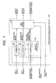
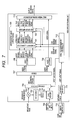
- Fig. 1 is a block diagram for showing the structures of a stereoscopic image display device, according to a first embodiment of the present invention.
- a stereoscopic image which is treated within the present embodiment, is a video or picture for use in a stereoscopic image display with using a stereoscopy, and it is constructed with two (2) pieces of input videos or pictures.
- two (2) pieces of input videos are displayed on an device for displaying the stereoscopic images thereon, such as, a display or a screen, etc., for example, at the same position, alternately, so that one of the input videos or images can be observed only by a left-side eye of a observer and the other thereof can be observed by only a right-side eye of the observer, for example, through a method of observing the images through a pair of shutter glasses, which are in synchronism with timing of the device thereof for displaying the videos.
- the device shown in Fig. 1 is able to execute a control of disparity and superimposing of the OSD upon the input video, thereby to output it.
- the entire structures of the stereoscopic image display device are shown by a reference numeral 100.
- the stereoscopic image display device is constructed with a disparity corrector 101 and an OSD superimposer.
- the disparity corrector is constructed with a disparity controller 151 an L-corrector 152 and an R-corrector 153.
- Explanation will be made on a flow of signals within the stereoscopic image display device.
- An input image L and an input image R, building up a stereoscopic image are inputted into the disparity controller portion, wherein the disparities are corrected with the method, which will be mentioned later, and a corrected image L and a corrected image R are outputted therefrom.
- the disparity controller determines a correction method and a correction amount of the disparity when correcting the input image, upon basis of the maximum disparity signals of an OSD display signal, an OSD disparity signal and an input image. Explanation about a method for correcting the disparity and a method for determining the correction amount will be made later.
- the L-corrector conducts a video processing on an intermediate image L, upon basis of the correction method and the correction volume, which are determined within the disparity controller, and thereby outputs the corrected image L.
- the R-corrector conducts video processing on an intermediate image R, upon basis of the correction method and the correction volume, which are determined within the disparity controller, and thereby outputs the corrected image R.
- characters and/or pictures, etc. are overlaid or superimposed in a part of the corrected image L and the corrected image R, respectively, and are outputted as an output image L and an output image R.
- the OSD superimposer overlays or superimposes the flat OSD onto the corrected images L and R, and output the output images L and R.
- the OSD superimposer it is possible to overlay or superimpose a menu screen and/or captions having an arbitrary disparity, or a graphic (CG) produced by a computer, etc., onto the corrected images L and R.
- the OSD is superimposed when the OSD display signal comes to be a value of meaning "ON”, while it is not superimposed when the OSD display signal comes to be a value of meaning "OFF”.
- the OSD display signal can be defined by a signal of 1 bit, and wherein it can be determined that "1" means "ON” and "0" means "OFF".
- the amounts or volumes of the disparity, which are applied onto the output image L and the output image R, are determined on the OSD disparity signal, which is applied from an outside of the stereoscopic image display device and the correction maximum disparity signal, which is applied from the disparity controller.
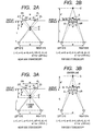
- Figs. 2A and 2B are views for explaining the principle of the way [A].
- FIG. 2A and 2B depict the state that an observer watches the device from a front surface thereof while displaying the input image L for the left-side eye and the input image R for the right-side eye on that device, which can display the stereoscopic image with using the stereoscopy.
- the surface, on which the input image is displayed, is called by a display surface.
- the input image L and the input image R are displayed on the display surface at the same position.
- the input images can be recognized in a stereoscopic manner, in accordance with the stereoscopy.
- a distance between the left-side eye and the right-side eye of the observer is "e” (e>0), and that a distance between the observer and the display surface is "L” (L>0).
- a bright point "PL”, displaying a certain pixel on the input video L before correction, and a bright point "PR”, displaying a certain pixel on the input video R on the display are formed as images, at the same point (a point image) "S" on a stereoscopic space, and that they are recognized as a part of the stereoscopic image by the observer.
- a distance "w” between "PR” and "PL” on the display surface is called by "disparity”.
- the distance “w” is defined to be positive when “PR” lies on the left side than “PL” judging from the observer, and is zero “0" when the positions of "PR” and “PL” are at the same position on the display, and further the distance is defined to be negative when "PR” is on the right side than "PL” judging from the observer.
- the point image "S" is formed at the same position on the display surface, then for the observer it can be sensed to be a point laying on the display.
- the point image "S” is formed on a side in front than the display, and then it can be sensed to be a point having depth in the jumping out direction (i.e., near side stereoscopy).
- the point image "S” is formed on a depth side than the display, and then it can be sensed to be a point having depth in the drawing back direction for the observer(i.e., far side stereoscopy).
- a distance between the point image "S" and the display is defined as an amount or volume of jumping out "d”.
- Fig. 2A shows a result of a case of applying the method [A] on a solid body of the jumping out direction (near side stereoscopy)
- Fig. 2B shows a result of a case of applying the method [A] on a solid body of the drawing back direction (far side stereoscopy).
- the input image L after being shifted to the left-hand side by " ⁇ L" ( ⁇ L>0) within the L-corrector, is outputted as the corrected image L
- the input image R after being shifted to the right-hand side by " ⁇ R" ( ⁇ R>0) within the R-corrector, is outputted as the corrected image R.
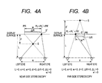
- Fig. 3A shows a result when applying the method [B] onto the solid body of the jumping out direction (near side stereoscopy), while Fig. 3B shows a result when applying the method [B] onto the solid body of the drawing back direction (far side stereoscopy).
- the image, obtained by shrinking the horizontal direction of the input image L down to "w'/w” within the L-corrector is outputted, as the corrected image L
- the image, obtained by shrinking the horizontal direction of the input image R down to "w'/w” within the R-corrector is outputted, as the corrected image R, respectively.
- Figs. 4A and 4B are explanatory views for showing the [C] correction method with using a flat image therein. Meanings of the marks are same to those in Figs. 2A and 2B .
- the method [C] while using the input images L and R, one (1) piece of flat image is produced, and also a same flat image is outputted, as both, the corrected images L and R.
- a method for producing the flat image in more details thereof, there are several methods; e.g., a method of using either one of the input images L or R, as the flat image, and a method of creating out one (1) piece of image through the morphing technology with using the input image L and the input image R, etc.
- a plane control selector 952 is a selector for executing the correction according to the method [C].
- the plane control selector is connected on ( ⁇ ) side in Fig. 9
- the plane video is produced, it is connected on ( ⁇ ) side.
- it When it is connected on the ( ⁇ ) side, it outputs the same video to both, intermediate images L and R, thereby enabling to correct the disparity at all of the points, which are included in the intermediate images.
- a method of conducting such a display of obtaining a horizontal image size, being large at a certain degree, within a range of the disparity, in which always it can be viewed comfortably with applying the method [A] or [B] when the correction volume is less than a constant value, and by changing into the method [C] when the correction volume is larger than the constant value.
- the structure shown in Fig. 10 is adopted.
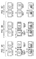
- Figs. 5A to 5C show screen images when applying the methods [A] to [C] as the correction method, respectively.
- Fig. 5A is shown an image of the video when conducting the correction thereon, in accordance with the method [A].
- the left-hand side of a corrected image L 502 is a region where an input image L 501 is shifted in parallel to the left to be disposed.
- Video data being on the input image, but of a region coming out into an outside of the screen through parallel shifting on the corrected image, is not used.
- a region 505 other than where the input images are disposed is filled up with a pattern, being visually unremarkable, such as, a black color, a gray color, or a specific pattern, etc., so that it does not obstacle or disturb by the observer.
- the output image L is the image, which is obtained by superimposing the OSD 506 on the corrected image L with a method, the details of which will be shown later. Also, with the input image R and the output image R, the direction of the parallel shifting thereof is on the right-hand side, and the images are outputted after being conducted with the similar processing thereon, but other than that the position of superimposing the OSD is on the L side differing from.
- Fig. 5B shows a video image when conducting the correction in accordance with the method [B].
- a region 516 other than that where the input images are disposed is filled with the black, the gray or the specific pattern, in the similar manner to that in case of the method [A].
- the shrinkage may be made in the vertical direction at the same time.
- the conduction ratios are determined to be same in the vertical direction and the horizontal direction, there can be obtained a merit that the shrinkage can be made while fixing an aspect ratio, and when not shrinking in the vertical direction, there can be obtained a merit that an area occupied by the input image comes to be large on the out image.
- Fig. 5C shows a video image when conducting the correction in accordance with the method [C].
- the disparity of the corrected image is made zero (0) by outputting the same image to both the corrected images L and R.
- the OSD is displayed in front than the flat image.
- both the flat image and the OSD can be formed on the display surface, thereby enabling so-called 2-D display.
- Fig. 6 is a flowchart for showing a flow of operations of the stereoscopic image display device. The correction method and the correction volume are determined, as is shown in this flowchart.
- WIN is an input maximum disparity signal, i.e., a signal defining the maximum disparities in the jumping out direction of the input images L and R.
- a value of disparity presents the jumping out direction by a positive value while the drawing back direction by a negative value.
- a video source such as, an optical disc medium recording the stereoscopic image thereon and/or a radio wave, etc.
- a signal defining the disparity of an input image is given accompanying with the input image.
- the purpose of giving such signal is to adjust the disparity depending on the visual condition, such as, the position of a visual point of the observer, an inch size of the display, etc., for example.
- the disparity signal is defined, respectively, by a screen area, such as, a unit of a pixel/area/screen as a whole, etc., for example, or by a time unit, such as, by each (1) frame/by plural frames/video as a whole, etc., and by the jumping out direction (the maximum disparity signal)/the drawing back direction (the minimum disparity signal).
- the maximum value is obtained, in relation to the disparity in the jumping out direction, at least during a period of one (1) frame or more than that, from the disparity given, and defines it as the maximum disparity signal "WIN".
- Fig. 11 shows the structures when obtaining "WIN” by analyzing the input images and so on.
- a disparity analysis portion 1100 in Fig. 11 presumes the maximum disparity from the input image L and the input image R, and outputs it as the input maximum disparity signal.
- the OSD is displayed during only the period when the OSD display signal becomes "1".
- the signal, indicating the disparity to be attached on the OSD, i.e., the OSD disparity signal is indicated by "WOSD".
- a value of "WOSD” may be selected from selections, large, middle, small or the like, by a user on the menu screen, etc., or may be determined by a method of using a fixed value, which is determined in advance.
- the value of "WOSD” may be a positive, zero (0), or a negative. A case where it is the negative presents that the OSD lies in the drawing back direction than the display.
- the disparity WOSD is provided on the OSD video, such as, the plane characters and/or pictures, etc., thereby adjusting a sense of depth of the OSD.
- a value "WOUT" of the output maximum disparity signal is a signal, indicating the maximum value of the disparity in the jumping out direction on the output images L and R, and when displaying the OSD, it comes to WOSD, being the disparity of the OSD, and when not displaying the OSD, it comes to a value WIN of the maximum disparity signal of the input image.
- the maximum disparity of the input image is set to be large in the jumping out direction thereof, it is not necessary to provide the position displaying the OSD in front, but not so much, and it results into lessening a load bearing on the eyes of the observer.
- the disparity of the OSD comes to zero (0), and thereby enabling to suppress the visual fatigue of the observer when she/he watches the OSD, carefully, down to the minimum.
- correction processes such as, the methods [A] to [C], for example, and also the superimpose process of OSD are executed only by simple processes, such as, the parallel shifting or the shrinkage of the video, or exchanging of data path, for example, it can be achieved with a relatively simple hardware structure.
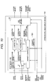
- Fig. 7 is a block diagram for showing the structure of a video recorder including the stereoscopic image display device therein, according to a second embodiment of the present invention.
- This device picks up input video data, building up the stereoscopic image, from a broadcast wave received, a HDD (Hard Disc Drive) or an optical disc medium, for example, and after implementing the correction of disparity and the superimposing of OSD within the stereoscopic image display device, the output image is outputted to an outside of the video recorder main unit. Also, as the information attached on the output image, the output maximum disparity signal is outputted to the outside of the video recorder main unit.
- HDD Hard Disc Drive
- the video recorder main unit is constructed with a stereoscopic image display device 100, a broadcast wave receiver 701, a trans-coder 702, a HDD 703, an optical disc medium 704, a data reader 705, a stream selector 706, a DEMUX 707, a video recorder 708, an audio recorder 709, a remote control unit 710, a video recorder main unit 711, and a video recorder main unit controller 712.
- the OSD may be video information, for example, a line of characters, captions or the like, such as, captions, program information, and/or an icon, etc., other than the menu screen.
- the disparity in the jumping out direction, to be attached on the OSD i.e., the OSD disparity signal is outputted from the video recorder main unit controller.
- the OSD disparity signal is made selectable from the menu screen, for the user with using the remote control unit.
- the output maximum disparity signal is transferred to the equipment on the latter stage, including it within output multimedia signals.
- Fig. 7 although such structure is adopted that the output images L and R, the output maximum disparity and the audio signal are collected together, to be outputted to an outside, as an output multimedia signal; however, it may be in other structure of outputting them to the outside, actually, as individual independent signals.
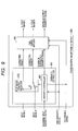
- Fig. 8 is a block diagram for showing the structure of a television receiver including the stereoscopic image display device therein, according to a third embodiment of the present invention.
- This device picks up input video data, building up the stereoscopic image, from the broadcast wave received, or an input signal from an outside of that device, and after implementing the correction of disparity and the superimposing of OSD within the stereoscopic image display device, the video is displayed on a display.
- An input signal may be, for example, the output multimedia signal, which is outputted from the video recorder main unit according to the embodiment 2, and so on.
- the television main unit is constructed with the stereoscopic image display device 100, the broadcast wave receiver 701, the DEMUX 707, the video recorder 708, the audio recorder 709, the remote control unit 710, and the main unit controller 711, and in addition thereto, a multimedia signal separator 801, a selector 802, a television main unit controller 803, a display 804 and a speaker 805.
- the jumping out volume and the drawing back volume also become large, it is possible to cause the observer to sense the stereoscopic sense, strongly; however, actually, there is so-called a merger limit, and therefore, if the disparity is enlarged more than a certain degree, it results in that stereoscopy cannot be obtained, or generates the visual fatigue, etc. For that reason, it is necessary to adjust the disparity, fitting to the size of the display, on which the display is made. Then, according to the display shown in the present embodiment, with comparing the output maximum disparity signal and the merger limit, when displaying the output videos L and R thereon, adjustment is made on the disparity so that the disparity is not provided more than the merger limit.
Landscapes
- Engineering & Computer Science (AREA)
- Multimedia (AREA)
- Signal Processing (AREA)
- Human Computer Interaction (AREA)
- Testing, Inspecting, Measuring Of Stereoscopic Televisions And Televisions (AREA)
- Controls And Circuits For Display Device (AREA)
- Processing Or Creating Images (AREA)
Applications Claiming Priority (1)
| Application Number | Priority Date | Filing Date | Title |
|---|---|---|---|
| JP2010080128A JP2011216937A (ja) | 2010-03-31 | 2010-03-31 | 立体画像表示装置 |
Publications (1)
| Publication Number | Publication Date |
|---|---|
| EP2373044A1 true EP2373044A1 (en) | 2011-10-05 |
Family
ID=43415783
Family Applications (1)
| Application Number | Title | Priority Date | Filing Date |
|---|---|---|---|
| EP10015045A Withdrawn EP2373044A1 (en) | 2010-03-31 | 2010-11-26 | Stereoscopic image display device |
Country Status (4)
| Country | Link |
|---|---|
| US (1) | US20110242296A1 (enExample) |
| EP (1) | EP2373044A1 (enExample) |
| JP (1) | JP2011216937A (enExample) |
| CN (1) | CN102209249A (enExample) |
Families Citing this family (11)
| Publication number | Priority date | Publication date | Assignee | Title |
|---|---|---|---|---|
| JP5402715B2 (ja) * | 2009-06-29 | 2014-01-29 | ソニー株式会社 | 立体画像データ送信装置、立体画像データ送信方法、立体画像データ受信装置および立体画像データ受信方法 |
| KR101899821B1 (ko) * | 2010-12-03 | 2018-11-02 | 엘지전자 주식회사 | 다시점 3차원 방송 신호를 수신하기 위한 수신 장치 및 방법 |
| KR101309783B1 (ko) * | 2011-12-30 | 2013-09-23 | 삼성전자주식회사 | 디스플레이 장치 및 방법 |
| WO2014024649A1 (ja) | 2012-08-06 | 2014-02-13 | ソニー株式会社 | 画像表示装置および画像表示方法 |
| WO2015002442A1 (ko) * | 2013-07-02 | 2015-01-08 | 엘지전자 주식회사 | 다시점 영상이 제공되는 시스템에서 부가 오브젝트를 포함하는 3차원 영상 처리 방법 및 장치 |
| KR102143472B1 (ko) | 2013-07-26 | 2020-08-12 | 삼성전자주식회사 | 다시점 영상 처리 장치 및 그 영상 처리 방법 |
| CN103458262B (zh) * | 2013-09-24 | 2015-07-29 | 武汉大学 | 一种3d图像空间与3d视听空间转换方法及装置 |
| CN105654526B (zh) * | 2015-12-31 | 2018-07-20 | 南京华捷艾米软件科技有限公司 | 一种基于双向扫描的视差图生成方法及电路设计 |
| US11107268B2 (en) * | 2018-09-07 | 2021-08-31 | Cognex Corporation | Methods and apparatus for efficient data processing of initial correspondence assignments for three-dimensional reconstruction of an object |
| JP7415439B2 (ja) * | 2019-10-28 | 2024-01-17 | セイコーエプソン株式会社 | プロジェクターの制御方法及びプロジェクター |
| TWI812566B (zh) * | 2022-12-28 | 2023-08-11 | 宏碁股份有限公司 | 立體影像深度調整方法與裝置 |
Citations (7)
| Publication number | Priority date | Publication date | Assignee | Title |
|---|---|---|---|---|
| EP0905988A1 (en) * | 1997-09-30 | 1999-03-31 | Kabushiki Kaisha Toshiba | Three-dimensional image display apparatus |
| JPH11187426A (ja) | 1997-12-18 | 1999-07-09 | Victor Co Of Japan Ltd | 立体映像装置及び方法 |
| WO2008115222A1 (en) * | 2007-03-16 | 2008-09-25 | Thomson Licensing | System and method for combining text with three-dimensional content |
| US20100021141A1 (en) * | 2008-07-24 | 2010-01-28 | Panasonic Corporation | Play back apparatus, playback method and program for playing back 3d video |
| WO2010010499A1 (en) * | 2008-07-25 | 2010-01-28 | Koninklijke Philips Electronics N.V. | 3d display handling of subtitles |
| US20100045779A1 (en) * | 2008-08-20 | 2010-02-25 | Samsung Electronics Co., Ltd. | Three-dimensional video apparatus and method of providing on screen display applied thereto |
| WO2010058368A1 (en) * | 2008-11-24 | 2010-05-27 | Koninklijke Philips Electronics N.V. | Combining 3d video and auxiliary data |
Family Cites Families (9)
| Publication number | Priority date | Publication date | Assignee | Title |
|---|---|---|---|---|
| US6392689B1 (en) * | 1991-02-21 | 2002-05-21 | Eugene Dolgoff | System for displaying moving images pseudostereoscopically |
| DE602006017940D1 (de) * | 2005-09-09 | 2010-12-16 | Olympus Medical Systems Corp | Medizinisches Stereo-Beobachtungssystem |
| US20100091012A1 (en) * | 2006-09-28 | 2010-04-15 | Koninklijke Philips Electronics N.V. | 3 menu display |
| KR101419979B1 (ko) * | 2008-01-29 | 2014-07-16 | 톰슨 라이센싱 | 2d 이미지 데이터를 스테레오스코픽 이미지 데이터로 변환하기 위한 방법 및 시스템 |
| US8335425B2 (en) * | 2008-11-18 | 2012-12-18 | Panasonic Corporation | Playback apparatus, playback method, and program for performing stereoscopic playback |
| CN102210156B (zh) * | 2008-11-18 | 2013-12-18 | 松下电器产业株式会社 | 进行立体视觉再生的再生装置、再生方法 |
| JP4714307B2 (ja) * | 2009-05-19 | 2011-06-29 | パナソニック株式会社 | 記録媒体、再生装置、符号化装置、集積回路、及び再生出力装置 |
| MX2011002003A (es) * | 2009-07-10 | 2011-03-29 | Panasonic Corp | Medio de grabacion, dispositivo de reproduccion y circuito integrado. |
| US8270807B2 (en) * | 2009-07-13 | 2012-09-18 | Panasonic Corporation | Recording medium, playback device, and integrated circuit |
-
2010
- 2010-03-31 JP JP2010080128A patent/JP2011216937A/ja not_active Withdrawn
- 2010-11-26 EP EP10015045A patent/EP2373044A1/en not_active Withdrawn
- 2010-11-29 US US12/955,425 patent/US20110242296A1/en not_active Abandoned
- 2010-11-30 CN CN2010105732402A patent/CN102209249A/zh active Pending
Patent Citations (7)
| Publication number | Priority date | Publication date | Assignee | Title |
|---|---|---|---|---|
| EP0905988A1 (en) * | 1997-09-30 | 1999-03-31 | Kabushiki Kaisha Toshiba | Three-dimensional image display apparatus |
| JPH11187426A (ja) | 1997-12-18 | 1999-07-09 | Victor Co Of Japan Ltd | 立体映像装置及び方法 |
| WO2008115222A1 (en) * | 2007-03-16 | 2008-09-25 | Thomson Licensing | System and method for combining text with three-dimensional content |
| US20100021141A1 (en) * | 2008-07-24 | 2010-01-28 | Panasonic Corporation | Play back apparatus, playback method and program for playing back 3d video |
| WO2010010499A1 (en) * | 2008-07-25 | 2010-01-28 | Koninklijke Philips Electronics N.V. | 3d display handling of subtitles |
| US20100045779A1 (en) * | 2008-08-20 | 2010-02-25 | Samsung Electronics Co., Ltd. | Three-dimensional video apparatus and method of providing on screen display applied thereto |
| WO2010058368A1 (en) * | 2008-11-24 | 2010-05-27 | Koninklijke Philips Electronics N.V. | Combining 3d video and auxiliary data |
Also Published As
| Publication number | Publication date |
|---|---|
| JP2011216937A (ja) | 2011-10-27 |
| CN102209249A (zh) | 2011-10-05 |
| US20110242296A1 (en) | 2011-10-06 |
Similar Documents
| Publication | Publication Date | Title |
|---|---|---|
| EP2373044A1 (en) | Stereoscopic image display device | |
| US8605136B2 (en) | 2D to 3D user interface content data conversion | |
| US9451242B2 (en) | Apparatus for adjusting displayed picture, display apparatus and display method | |
| US9124870B2 (en) | Three-dimensional video apparatus and method providing on screen display applied thereto | |
| US8930838B2 (en) | Display apparatus and display method thereof | |
| EP2410753B1 (en) | Image-processing method for a display device which outputs three-dimensional content, and display device adopting the method | |
| EP2446635B1 (en) | Insertion of 3d objects in a stereoscopic image at relative depth | |
| US20130038611A1 (en) | Image conversion device | |
| EP2365699A2 (en) | Method for adjusting 3D image quality, 3D display apparatus, 3D glasses, and system for providing 3D image | |
| EP2448275A2 (en) | GUI providing method, and display apparatus and 3D image providing system using the same | |
| US20110228057A1 (en) | Image Processing Apparatus, Image Conversion Method, and Program | |
| TW201223245A (en) | Displaying graphics with three dimensional video | |
| KR20110122057A (ko) | 설정 메뉴를 디스플레이하기 위한 방법 및 대응하는 디바이스 | |
| US20120075291A1 (en) | Display apparatus and method for processing image applied to the same | |
| WO2012036120A1 (ja) | 立体画像生成装置、立体画像表示装置、立体画像調整方法、立体画像調整方法をコンピュータに実行させるためのプログラム、及びそのプログラムを記録した記録媒体 | |
| TWI555400B (zh) | 應用於顯示裝置的字幕控制方法與元件 | |
| US9407901B2 (en) | Method of displaying content list using 3D GUI and 3D display apparatus applied to the same | |
| JP5117613B1 (ja) | 映像処理装置および映像処理方法ならびに記憶媒体 | |
| WO2012120880A1 (ja) | 立体画像出力装置及び立体画像出力方法 | |
| WO2012014489A1 (ja) | 映像信号処理装置及び映像信号処理方法 | |
| EP2421271B1 (en) | Display apparatus and method for applying on screen display (OSD) thereto | |
| KR101728724B1 (ko) | 영상 표시 방법 및 그에 따른 영상 표시 장치 | |
| JP2011223126A (ja) | 立体映像表示装置および立体映像表示方法 | |
| US9547933B2 (en) | Display apparatus and display method thereof | |
| JP2014225736A (ja) | 画像処理装置 |
Legal Events
| Date | Code | Title | Description |
|---|---|---|---|
| PUAI | Public reference made under article 153(3) epc to a published international application that has entered the european phase |
Free format text: ORIGINAL CODE: 0009012 |
|
| 17P | Request for examination filed |
Effective date: 20110331 |
|
| AK | Designated contracting states |
Kind code of ref document: A1 Designated state(s): AL AT BE BG CH CY CZ DE DK EE ES FI FR GB GR HR HU IE IS IT LI LT LU LV MC MK MT NL NO PL PT RO RS SE SI SK SM TR |
|
| AX | Request for extension of the european patent |
Extension state: BA ME |
|
| 17Q | First examination report despatched |
Effective date: 20120503 |
|
| STAA | Information on the status of an ep patent application or granted ep patent |
Free format text: STATUS: THE APPLICATION IS DEEMED TO BE WITHDRAWN |
|
| 18D | Application deemed to be withdrawn |
Effective date: 20140603 |