EP2372090B1 - Apparatus for cooling a bucket assembly - Google Patents
Apparatus for cooling a bucket assembly Download PDFInfo
- Publication number
- EP2372090B1 EP2372090B1 EP11158418.1A EP11158418A EP2372090B1 EP 2372090 B1 EP2372090 B1 EP 2372090B1 EP 11158418 A EP11158418 A EP 11158418A EP 2372090 B1 EP2372090 B1 EP 2372090B1
- Authority
- EP
- European Patent Office
- Prior art keywords
- bucket assembly
- cooling
- gas turbine
- turbine bucket
- sidewall
- Prior art date
- Legal status (The legal status is an assumption and is not a legal conclusion. Google has not performed a legal analysis and makes no representation as to the accuracy of the status listed.)
- Active
Links
Images


Classifications
-
- F—MECHANICAL ENGINEERING; LIGHTING; HEATING; WEAPONS; BLASTING
- F01—MACHINES OR ENGINES IN GENERAL; ENGINE PLANTS IN GENERAL; STEAM ENGINES
- F01D—NON-POSITIVE DISPLACEMENT MACHINES OR ENGINES, e.g. STEAM TURBINES
- F01D5/00—Blades; Blade-carrying members; Heating, heat-insulating, cooling or antivibration means on the blades or the members
- F01D5/12—Blades
- F01D5/14—Form or construction
- F01D5/18—Hollow blades, i.e. blades with cooling or heating channels or cavities; Heating, heat-insulating or cooling means on blades
- F01D5/186—Film cooling
-
- F—MECHANICAL ENGINEERING; LIGHTING; HEATING; WEAPONS; BLASTING
- F01—MACHINES OR ENGINES IN GENERAL; ENGINE PLANTS IN GENERAL; STEAM ENGINES
- F01D—NON-POSITIVE DISPLACEMENT MACHINES OR ENGINES, e.g. STEAM TURBINES
- F01D11/00—Preventing or minimising internal leakage of working-fluid, e.g. between stages
- F01D11/005—Sealing means between non relatively rotating elements
- F01D11/006—Sealing the gap between rotor blades or blades and rotor
-
- F—MECHANICAL ENGINEERING; LIGHTING; HEATING; WEAPONS; BLASTING
- F01—MACHINES OR ENGINES IN GENERAL; ENGINE PLANTS IN GENERAL; STEAM ENGINES
- F01D—NON-POSITIVE DISPLACEMENT MACHINES OR ENGINES, e.g. STEAM TURBINES
- F01D25/00—Component parts, details, or accessories, not provided for in, or of interest apart from, other groups
- F01D25/08—Cooling; Heating; Heat-insulation
- F01D25/12—Cooling
-
- F—MECHANICAL ENGINEERING; LIGHTING; HEATING; WEAPONS; BLASTING
- F01—MACHINES OR ENGINES IN GENERAL; ENGINE PLANTS IN GENERAL; STEAM ENGINES
- F01D—NON-POSITIVE DISPLACEMENT MACHINES OR ENGINES, e.g. STEAM TURBINES
- F01D5/00—Blades; Blade-carrying members; Heating, heat-insulating, cooling or antivibration means on the blades or the members
- F01D5/12—Blades
- F01D5/14—Form or construction
- F01D5/18—Hollow blades, i.e. blades with cooling or heating channels or cavities; Heating, heat-insulating or cooling means on blades
- F01D5/181—Blades having a closed internal cavity containing a cooling medium, e.g. sodium
-
- F—MECHANICAL ENGINEERING; LIGHTING; HEATING; WEAPONS; BLASTING
- F01—MACHINES OR ENGINES IN GENERAL; ENGINE PLANTS IN GENERAL; STEAM ENGINES
- F01D—NON-POSITIVE DISPLACEMENT MACHINES OR ENGINES, e.g. STEAM TURBINES
- F01D5/00—Blades; Blade-carrying members; Heating, heat-insulating, cooling or antivibration means on the blades or the members
- F01D5/12—Blades
- F01D5/22—Blade-to-blade connections, e.g. for damping vibrations
- F01D5/24—Blade-to-blade connections, e.g. for damping vibrations using wire or the like
-
- F—MECHANICAL ENGINEERING; LIGHTING; HEATING; WEAPONS; BLASTING
- F01—MACHINES OR ENGINES IN GENERAL; ENGINE PLANTS IN GENERAL; STEAM ENGINES
- F01D—NON-POSITIVE DISPLACEMENT MACHINES OR ENGINES, e.g. STEAM TURBINES
- F01D5/00—Blades; Blade-carrying members; Heating, heat-insulating, cooling or antivibration means on the blades or the members
- F01D5/12—Blades
- F01D5/26—Antivibration means not restricted to blade form or construction or to blade-to-blade connections or to the use of particular materials
-
- F—MECHANICAL ENGINEERING; LIGHTING; HEATING; WEAPONS; BLASTING
- F01—MACHINES OR ENGINES IN GENERAL; ENGINE PLANTS IN GENERAL; STEAM ENGINES
- F01D—NON-POSITIVE DISPLACEMENT MACHINES OR ENGINES, e.g. STEAM TURBINES
- F01D5/00—Blades; Blade-carrying members; Heating, heat-insulating, cooling or antivibration means on the blades or the members
- F01D5/30—Fixing blades to rotors; Blade roots ; Blade spacers
-
- F—MECHANICAL ENGINEERING; LIGHTING; HEATING; WEAPONS; BLASTING
- F05—INDEXING SCHEMES RELATING TO ENGINES OR PUMPS IN VARIOUS SUBCLASSES OF CLASSES F01-F04
- F05D—INDEXING SCHEME FOR ASPECTS RELATING TO NON-POSITIVE-DISPLACEMENT MACHINES OR ENGINES, GAS-TURBINES OR JET-PROPULSION PLANTS
- F05D2260/00—Function
- F05D2260/20—Heat transfer, e.g. cooling
- F05D2260/202—Heat transfer, e.g. cooling by film cooling
Definitions
- the subject matter disclosed herein relates generally to turbine buckets, and more specifically to cooling apparatus for bucket assembly components.
- Gas turbine systems are widely utilized in fields such as power generation.
- a conventional gas turbine system includes a compressor, a combustor, and a turbine.
- various components in the system are subjected to high temperature flows, which can cause the components to fail. Since higher temperature flows generally result in increased performance, efficiency, and power output of the gas turbine system, the components that are subjected to high temperature flow must be cooled to allow the gas turbine system to operate at increased temperatures.
- a cooling medium may be routed from the compressor and provided to various components.
- the cooling medium may be utilized to cool various turbine components.
- Turbine buckets are one example of a hot gas path component that must be cooled.
- Imperfectly sealed bucket shanks may allow hot gas to enter the shanks, and the hot gas can cause the bucket to fail.
- the hot gas can cause shank seal pins to creep and deform, and may cause the seal pins to extrude from the shanks. Further, the hot gas can damage the shank damper pins and the shanks themselves, resulting in failure of the buckets.
- cooling bucket shank components Various strategies are known in the art for cooling bucket shank components and preventing hot gas ingestion.
- one prior art strategy utilizes a high pressure flow of the cooling medium to pressurize the shank cavities, providing a positive back-flow margin for all hot gas ingestion locations on the shank. This positive back-flow margin prevents the hot gas from entering and damaging the shanks.
- the amount of cooling medium that must be routed from the compressor to pressurize the shank cavities is substantial, and this loss of flow through the compressor results in losses in performance, efficiency, and power output of the gas turbine system.
- a substantial amount of the cooling medium provided to pressurize the shank cavities is leaked and emitted from the shank cavities into the hot gas path, resulting in a waste of this cooling medium.
- a cooling apparatus for a bucket shank would be desired in the art.
- a cooling apparatus that minimizes the amount of cooling medium routed from the compressor and the amount of cooling medium wasted and lost during cooling of the bucket shank would be advantageous.
- a cooling apparatus that maximizes the performance, efficiency, and power output of the gas turbine system while effectively cooling the bucket shank would be advantageous.
- EP1621735 A2 discloses a gas turbine rotor having blades with inner space cooled and a mechanical sealing and damping component between the opposing side surfaces of adjacent blade platforms.
- US 2010/054954 A1 discloses a turbine bucket for a turbomachine that includes a main body portion having a base portion and an airfoil portion, the base portion including a bucket cavity forward region and a shank cavity.
- the turbine bucket also includes a cooling channel that extends through the main body portion. At least one flow passage extends between one of the cooling channels and the shank cavity, toward the bucket cavity forward region.
- EP1788192 A2 discloses, in a turbine bucket having an airfoil portion and a root portion with a substantially planar platform at an interface between the airfoil portion and the root portion, a platform cooling arrangement including a cavity extending along the forward portion of the platform, and at least one inlet bore extending from a source of cooling medium to the cavity, and at least one outlet opening for expelling cooling medium from the cavity.
- a gas turbine bucket assembly in one embodiment, includes a platform, an airfoil, and a shank.
- the airfoil extends radially outward from the platform.
- the shank extends radially inward from the platform.
- the shank includes a pressure side sidewall, a suction side sidewall, an upstream sidewall, and a downstream sidewall.
- the sidewalls define at least partially a cooling circuit.
- the cooling circuit is configured to receive a cooling medium and provide the cooling medium to the airfoil.
- the upstream sidewall defines at least partially an interior cooling passage and at least partially an exterior ingestion zone.
- the cooling passage is configured to provide a portion of the cooling medium from the cooling circuit to the ingestion zone of an adjacent bucket assembly.
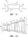
- FIG. 1 is a schematic diagram of a gas turbine system 10.
- the system 10 may include a compressor 12, a combustor 14, and a turbine 16.
- the compressor 12 and turbine 16 may be coupled by a shaft 18.
- the shaft 18 may be a single shaft or a plurality of shaft segments coupled together to form shaft 18.
- the turbine 16 may include a plurality of turbine stages.
- the turbine 16 may have three stages, as shown in FIG. 2 .
- a first stage of the turbine 16 may include a plurality of circumferentially spaced nozzles 21 and buckets 22.
- the nozzles 21 may be disposed and fixed circumferentially about the shaft 18.
- the buckets 22 may be disposed circumferentially about the shaft 18 and coupled to the shaft 18.
- a second stage of the turbine 16 may include a plurality of circumferentially spaced nozzles 23 and buckets 24.
- the nozzles 23 may be disposed and fixed circumferentially about the shaft 18.
- the buckets 24 may be disposed circumferentially about the shaft 18 and coupled to the shaft 18.
- a third stage of the turbine 16 may include a plurality of circumferentially spaced nozzles 25 and buckets 26.
- the nozzles 25 may be disposed and fixed circumferentially about the shaft 18.
- the buckets 26 may be disposed circumferentially about the shaft 18 and coupled to the shaft 18.
- the various stages of the turbine 16 may be disposed in the turbine 16 in the path of hot gas flow 28. It should be understood that the turbine 16 is not limited to three stages, but may have any number of stages known in the turbine art.
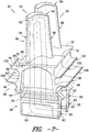
- Each of the buckets 22, 24, 26 may comprise a bucket assembly 30, as shown in FIG. 3 .
- the bucket assembly 30 may include a platform 32, an airfoil 34, and a shank 36.
- the airfoil 34 may extend radially outward from the platform 32.
- the shank 36 may extend radially inward from the platform 32.
- the bucket assembly 30 may further include a dovetail 38.
- the dovetail 38 may extend radially inward from the shank.
- the dovetail 38 may be configured to couple the bucket assembly 30 to the shaft 18.
- the dovetail 38 may secure the bucket assembly 30 to a rotor disk (not shown) disposed on the shaft 18.
- a plurality of bucket assemblies 30 may thus be disposed circumferentially about the shaft 18 and coupled to the shaft 18, forming a rotor assembly 20, as partially shown in FIGS. 6 and 7 .
- the dovetail 38 may be configured to supply a cooling medium 95 to a cooling circuit 90 defined within the bucket assembly 30.
- inlets 92 of the cooling circuit 90 may be defined by the dovetail 38.
- the cooling medium 95 may enter the cooling circuit 90 through the inlets 92.
- the cooling medium 95 may exit the cooling circuit 90 through, for example, film cooling holes, or through any other bucket assembly exit holes, passages, or aperatures.
- the cooling medium 95 is generally supplied to the turbine 16 from the compressor 12. It should be understood, however, that the cooling medium 95 is not limited to a cooling medium supplied by a compressor 12, but may be supplied by any system 10 component or external component. Further, the cooling medium 95 is generally cooling air. It should be understood, however, that the cooling medium 95 is not limited to air, and may be any cooling medium.
- the airfoil 34 may include a pressure side surface 52 and a suction side surface 54.
- the pressure side surface 52 and the suction side surface 54 may be connected at a leading edge 56 and a trailing edge 58.
- the airfoil 34 may at least partially define the cooling circuit 90 therein.
- the pressure side surface 52 and the suction side surface 54 may at least partially define the cooling circuit 90.
- the cooling circuit 90 may be configured to receive cooling medium 95 and provide the cooling medium to the airfoil 34.
- the cooling medium 95 may pass through the airfoil 34 within the cooling circuit 90, cooling the airfoil 34.
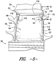
- the shank 36 may include a pressure side sidewall 42, a suction side sidewall 44 (see FIG. 5 ), an upstream sidewall 46, and a downstream sidewall 48.
- the upstream sidewall 46 of the shank 36 may include an exterior surface 62, an interior surface 64, a pressure side surface 66, and a suction side surface 68 (see FIG. 5 ).
- the shank 36 may at least partially define the cooling circuit 90 therein.
- the sidewalls 42, 44, 46, and 48 may at least partially define the cooling circuit 90.
- the shank 36 may further include an upstream upper angel wing 130, upstream lower angel wing 134, downstream upper angel wing 132, and downstream lower angel wing 136.
- the angel wings 130 and 134 may extend outwardly from the upstream sidewall 46, and the angel wings 132 and 136 may extend outwardly from the downstream sidewall 48.
- the upstream upper angel wing 130 and the downstream upper angel wing 132 may be configured to seal buffer cavities (not shown) defined within the rotor assembly 20.
- the upstream lower angel wing 134 and the downstream lower angel wing 136 may be configured to provide a seal between the bucket assembly 30 and the rotor disk (not shown).
- the shank 36 may further define an exterior ingestion zone 70.
- the exterior ingestion zone 70 is a zone between adjacent bucket assemblies 30 where the hot gas flow 28 enters the bucket assemblies 30.
- the ingestion zone 70 may be at least partially defined with respect to a bucket assembly 30 adjacent the suction side surface 68 of the upstream sidewall 46 and adjacent the platform 32.
- the ingestion zone 70 may be further defined with respect to a bucket assembly 30 adjacent the pressure side surface 66 of the upstream sidewall 46 and adjacent the platform 32.
- pressure gradients in the hot gas flow 28 may cause at least a portion of the hot gas flow 28 to be directed into a trench cavity 75 defined by the shank 36.
- the trench cavity 75 may be defined approximately adjacent the upstream upper angel wing 130.
- the hot gas flow 28 may be further directed from the trench cavity 75 through the ingestion zone 70 between and into the adjacent bucket assemblies 30.
- the bucket assembly 30 may include an upstream seal pin 112.
- the upstream seal pin 112 may be disposed adjacent the upstream sidewall 46, as shown in FIG. 5 .
- the upstream seal pin 112 may be disposed adjacent the suction side surface 68 of the upstream sidewall 46, and may be disposed in a channel 113 defined in the suction side surface 68 of the upstream sidewall 46.
- the channel 113 may be defined in the pressure side surface 66 of the upstream sidewall 46, and the upstream seal pin 112 may be disposed in the channel 113.
- channels 113 may be defined in both the suction side surface 68 and the pressure side surface 66, and the upstream seal pin 112 may be disposed in the channel 113 defined in the suction side surface 68 of the upstream sidewall 46 as well as in the channel 113 defined in the pressure side surface 66 of the upstream sidewall 46 of an adjacent bucket assembly 30.
- the bucket assembly 30 may further include a downstream seal pin 114, which may be disposed adjacent the downstream sidewall 48 in a channel 115, as shown in FIG. 5 .
- the channel 115 may be defined in the downstream sidewall 48 similarly to the channel 113 in the upstream sidewall 46.
- the seal pins 112 and 114 may be configured to provide a seal between the bucket assembly 30 and an adjacent bucket assembly 30.
- rotational forces may cause the seal pins 112 and 114 of a bucket 30 to interact with the upstream sidewall 46 and downstream sidewall 48, respectively, of the adjacent bucket 30, providing a seal between the bucket assemblies 30.
- the upstream seal pin 112 may interact with the pressure side surface 66 of the upstream sidewall 46, providing a seal between the bucket assemblies 30.
- the bucket assembly 30 may further include a damper pin 116.
- the damper pin 116 may be disposed adjacent the platform 32 and the suction side sidewall 44, or the platform 32 and the pressure side sidewall 42.
- the damper pin 116 may include a leading end 117 and a trailing end 118.
- the leading end 117 may be disposed adjacent the upstream sidewall 46.
- the trailing end 118 may be disposed adjacent the downstream sidewall 48.
- the damper pin 116 may be configured to dampen vibrations between the bucket assembly 30 and an adjacent bucket assembly 30. For example, during operation of the turbine 16, rotational forces may cause the damper pin 116 of a bucket 30 to interact with the platform 32 of the adjacent bucket 30, dampen vibrations between the bucket assemblies 30, as shown in FIG. 6 .
- the shank 36 of the bucket assembly 30 may further define an interior cooling passage 80.
- the cooling passage 80 may be configured to provide a portion of the cooling medium 95 from the cooling circuit 90 to the ingestion zone 70 of an adjacent bucket assembly 30.
- the cooling passage 80 may extend from the cooling circuit 90 through the shank 36.
- the cooling passage 80 may extend from the cooling circuit 90 at least partially through the upstream sidewall 46 of the shank 36.
- the cooling passage 80 may also extend, partially or entirely, through the pressure side sidewall 42, the suction side sidewall 44, or the downstream sidewall 48.
- the cooling passage 80 may further include an exterior cooling passage opening 84, as shown in FIG. 4 .
- the cooling passage opening 84 may be defined by the upstream sidewall 46, such as, for example, by the pressure side surface 66 of the upstream sidewall 46.
- the cooling passage opening 84 may be defined by the upstream sidewall 46 such as by the suction side surface 68 of the upstream sidewall 46.
- a portion of the cooling medium 95 may flow from the cooling circuit 90 through the cooling passage 80, and the cooling medium 95 may be exhausted from the cooling passage 80 through the cooling passage opening 84.
- the cooling medium 95 may be provided through the cooling passage 80 and cooling passage opening 84 to the ingestion zone 70 of an adjacent bucket assembly 30.
- a plurality of bucket assemblies 30 may be disposed circumferentially about the shaft 18 and coupled to the shaft 18, forming rotor assembly 20, as partially shown in FIGS. 6 and 7 .
- Each bucket assembly 30 and adjacent bucket assembly 30 may define an ingestion zone 70 therebetween, as shown in FIG. 6 .
- the cooling medium 95 provided to the ingestion zone 70 may interact with at least a portion of the seal pin 112 of the adjacent bucket assembly 30, cooling the upstream seal pin 112.
- an upper end 119 of the upstream seal pin 112 may be disposed adjacent to or within the ingestion zone 70.
- the cooling medium 95 provided to the ingestion zone 70 may interact with the upper end 119 of the seal pin 112, cooling the upper end 119.
- the exterior cooling passage opening 84 may be positioned upstream of the seal pin 112 with respect to the hot gas flow 28. In another exemplary aspect of an embodiment, the exterior cooling passage opening 84 may be substantially aligned with the seal pin 112 with respect to the hot gas flow 28. It should be understood, however, that the position of the exterior cooling passage opening 84 is not limited to a position upstream or in alignment with the seal pin 112, but may be anywhere on the shank 36 where the cooling medium 95 can be provided through the cooling passage opening 84 to the ingestion zone 70 of an adjacent bucket assembly 30.
- the cooling medium 95 provided to the ingestion zone 70 may interact with at least a portion of the damper pin 116 of the adjacent bucket assembly 30, cooling the damper pin 116.
- the leading end 117 of the damper pin 116 may be disposed adjacent to or within the ingestion zone 70.
- the cooling medium 95 provided to the ingestion zone 70 may interact with the leading end 117 of the damper pin 116, cooling the leading end 117.
- the cooling medium 95 upon exiting the cooling passage 80 through the cooling passage opening 84, may mix with the hot gas flow 28 in the ingestion zone 70, cooling the hot gas flow 28.
- the hot gas flow 28 may be at a temperature above approximately 1037.8 °C (1900 °F).
- the cooling medium 95 may mix with the hot gas flow 28, cooling the hot gas flow 28 to a temperature below approximately 1037.8 °C (1900 °F).
- the cooling medium 95 upon exiting the cooling passage 80 through the cooling passage opening 84, may provide an ingestion barrier.
- the ingestion barrier may prevent the hot gas flow 28 from entering the ingestion zone 70.
- the cooling medium 95 may exit the cooling passage 80 at a pressure sufficient to provide a localized cooling outflow, resulting in an ingestion barrier.
- the present disclosure is also directed to a method for cooling a bucket assembly 30.
- the method may include, for example, the step of providing a cooling medium 95 to a cooling circuit 90 within the bucket assembly 30.
- the cooling medium 95 may be provided from the compressor 12 through the dovetail 38 or shank 36 to the cooling circuit 90, as discussed above.
- the method may further include, for example, the step of providing a portion of the cooling medium 95 from the cooling circuit 90 through an interior cooling passage 80 to an exterior ingestion zone 70 of an adjacent bucket assembly 30.
- the bucket assembly 30 may include a platform 32, an airfoil 34, a shank 36, and a dovetail 38, as discussed above.
- the bucket assembly 30 may further include a seal pin 112, as discussed above.
- the bucket assembly 30 and the adjacent bucket assembly 30 may further define the ingestion zone 70 therebetween, and the cooling medium 95 provided to the ingestion zone 70 may interact with at least a portion of the seal pin 112 of the adjacent bucket assembly 30, cooling the seal pin 112, as discussed above.
- the cooling passage 80 may include an exterior cooling passage opening 84, as discussed above.
- the cooling passage opening 84 may be positioned, for example, upstream of the seal pin 112 with respect to a hot gas flow 28, or substantially aligned with the seal pin 112 with respect to the hot gas flow 28, as discussed above.
- the bucket assembly 30 may further include a damper pin 116, as discussed above.
- the bucket assembly 30 and the adjacent bucket assembly 30 may further define the ingestion zone 70 therebetween, and the cooling medium 95 provided to the ingestion zone 70 may interact with at least a portion of a leading end 117 of the damper pin 116 of the adjacent bucket assembly 30, cooling the leading end 117, as discussed above.
- the cooling medium 95 may mix with a hot gas flow 28 in the ingestion zone 70, cooling the hot gas flow 28, as discussed above.
- the cooling medium 95 may provide an ingestion barrier. The ingestion barrier may prevent a hot gas flow 28 from entering the ingestion zone 70, as discussed above.
- the amount of cooling medium 95 that is required to prevent ingestion of the hot gas flow 28, cool the seal pin 112, and cool the damper pin 116 according to the present disclosure may be a beneficially minimal amount.
- the required amount of cooling medium 95 that is supplied to the turbine 16 and the various bucket assemblies 30 from the compressor 12 may be substantially lower than the amounts required by various other bucket component cooling devices and designs, such as pressurized shank designs.
- the minimal amount of cooling medium 95 that is required according to the present disclosure may provide significant decreases in the amount of cooling medium 95 wasted through leakage and emission in the turbine 16 of the gas turbine system 10. Further, the minimal amount of cooling medium 95 that is required according to the present disclosure may provide significant increases in the performance and efficiency of the turbine 16 and the gas turbine system 10.
Landscapes
- Engineering & Computer Science (AREA)
- Mechanical Engineering (AREA)
- General Engineering & Computer Science (AREA)
- Turbine Rotor Nozzle Sealing (AREA)
- Structures Of Non-Positive Displacement Pumps (AREA)
Applications Claiming Priority (1)
| Application Number | Priority Date | Filing Date | Title |
|---|---|---|---|
| US12/728,517 US8540486B2 (en) | 2010-03-22 | 2010-03-22 | Apparatus for cooling a bucket assembly |
Publications (3)
| Publication Number | Publication Date |
|---|---|
| EP2372090A2 EP2372090A2 (en) | 2011-10-05 |
| EP2372090A3 EP2372090A3 (en) | 2014-10-22 |
| EP2372090B1 true EP2372090B1 (en) | 2019-05-22 |
Family
ID=44063243
Family Applications (1)
| Application Number | Title | Priority Date | Filing Date |
|---|---|---|---|
| EP11158418.1A Active EP2372090B1 (en) | 2010-03-22 | 2011-03-16 | Apparatus for cooling a bucket assembly |
Country Status (4)
| Country | Link |
|---|---|
| US (1) | US8540486B2 (enExample) |
| EP (1) | EP2372090B1 (enExample) |
| JP (1) | JP5865595B2 (enExample) |
| CN (1) | CN102200031B (enExample) |
Families Citing this family (19)
| Publication number | Priority date | Publication date | Assignee | Title |
|---|---|---|---|---|
| US8820754B2 (en) * | 2010-06-11 | 2014-09-02 | Siemens Energy, Inc. | Turbine blade seal assembly |
| US8979481B2 (en) * | 2011-10-26 | 2015-03-17 | General Electric Company | Turbine bucket angel wing features for forward cavity flow control and related method |
| FR2981979B1 (fr) * | 2011-10-28 | 2013-11-29 | Snecma | Roue de turbine pour une turbomachine |
| US10180067B2 (en) | 2012-05-31 | 2019-01-15 | United Technologies Corporation | Mate face cooling holes for gas turbine engine component |
| EP2877706A1 (en) * | 2012-06-15 | 2015-06-03 | General Electric Company | Rotor assembly, corresponding gas turbine engine and method of assembling |
| US10364680B2 (en) | 2012-08-14 | 2019-07-30 | United Technologies Corporation | Gas turbine engine component having platform trench |
| EP2762679A1 (en) * | 2013-02-01 | 2014-08-06 | Siemens Aktiengesellschaft | Gas Turbine Rotor Blade and Gas Turbine Rotor |
| EP2956627B1 (en) | 2013-02-15 | 2018-07-25 | United Technologies Corporation | Gas turbine engine component with combined mate face and platform cooling |
| EP3047105B1 (en) | 2013-09-17 | 2021-06-09 | Raytheon Technologies Corporation | Platform cooling core for a gas turbine engine rotor blade |
| US10066488B2 (en) * | 2015-12-01 | 2018-09-04 | General Electric Company | Turbomachine blade with generally radial cooling conduit to wheel space |
| US20170191366A1 (en) * | 2016-01-05 | 2017-07-06 | General Electric Company | Slotted damper pin for a turbine blade |
| CN105569741A (zh) * | 2016-02-03 | 2016-05-11 | 山东佳星环保科技有限公司 | 一种提高燃气初温的燃气轮机结构 |
| WO2018020548A1 (ja) * | 2016-07-25 | 2018-02-01 | 株式会社Ihi | ガスタービン動翼のシール構造 |
| US11401817B2 (en) * | 2016-11-04 | 2022-08-02 | General Electric Company | Airfoil assembly with a cooling circuit |
| US10648354B2 (en) | 2016-12-02 | 2020-05-12 | Honeywell International Inc. | Turbine wheels, turbine engines including the same, and methods of forming turbine wheels with improved seal plate sealing |
| EP3438410B1 (en) | 2017-08-01 | 2021-09-29 | General Electric Company | Sealing system for a rotary machine |
| US10890074B2 (en) * | 2018-05-01 | 2021-01-12 | Raytheon Technologies Corporation | Coriolis optimized u-channel with platform core |
| KR102248037B1 (ko) * | 2019-11-27 | 2021-05-04 | 두산중공업 주식회사 | 마그네틱 댐퍼를 구비하는 터빈 블레이드 |
| US12571351B2 (en) | 2023-06-14 | 2026-03-10 | General Electric Company | Gas turbine engine defining a rotor cavity |
Citations (3)
| Publication number | Priority date | Publication date | Assignee | Title |
|---|---|---|---|---|
| EP1621735A2 (de) * | 2004-07-28 | 2006-02-01 | Rolls-Royce Deutschland Ltd & Co KG | Gasturbinenrotor |
| EP1788192A2 (en) * | 2005-11-21 | 2007-05-23 | General Electric Company | Gas turbine bucket with cooled platform edge and method of cooling platform leading edge |
| US20100054954A1 (en) * | 2008-09-04 | 2010-03-04 | General Electric Company | Turbine bucket for a turbomachine and method of reducing bow wave effects at a turbine bucket |
Family Cites Families (14)
| Publication number | Priority date | Publication date | Assignee | Title |
|---|---|---|---|---|
| US2912223A (en) * | 1955-03-17 | 1959-11-10 | Gen Electric | Turbine bucket vibration dampener and sealing assembly |
| US3834831A (en) * | 1973-01-23 | 1974-09-10 | Westinghouse Electric Corp | Blade shank cooling arrangement |
| GB2252368B (en) * | 1981-03-20 | 1993-02-17 | Rolls Royce | Liquid cooled aerofoil blade |
| GB2254379B (en) * | 1981-04-28 | 1993-04-14 | Rolls Royce | Cooled aerofoil blade |
| US6341939B1 (en) * | 2000-07-31 | 2002-01-29 | General Electric Company | Tandem cooling turbine blade |
| US6428270B1 (en) * | 2000-09-15 | 2002-08-06 | General Electric Company | Stage 3 bucket shank bypass holes and related method |
| DE50009497D1 (de) * | 2000-11-16 | 2005-03-17 | Siemens Ag | Filmkühlung von Gasturbinenschaufeln mittels Schlitzen für Kühlluft |
| US6776583B1 (en) * | 2003-02-27 | 2004-08-17 | General Electric Company | Turbine bucket damper pin |
| US6851932B2 (en) * | 2003-05-13 | 2005-02-08 | General Electric Company | Vibration damper assembly for the buckets of a turbine |
| US7147440B2 (en) * | 2003-10-31 | 2006-12-12 | General Electric Company | Methods and apparatus for cooling gas turbine engine rotor assemblies |
| US7189063B2 (en) * | 2004-09-02 | 2007-03-13 | General Electric Company | Methods and apparatus for cooling gas turbine engine rotor assemblies |
| US7090466B2 (en) * | 2004-09-14 | 2006-08-15 | General Electric Company | Methods and apparatus for assembling gas turbine engine rotor assemblies |
| US7367123B2 (en) * | 2005-05-12 | 2008-05-06 | General Electric Company | Coated bucket damper pin and related method |
| US7575416B2 (en) * | 2006-05-18 | 2009-08-18 | United Technologies Corporation | Rotor assembly for a rotary machine |
-
2010
- 2010-03-22 US US12/728,517 patent/US8540486B2/en active Active
-
2011
- 2011-03-16 EP EP11158418.1A patent/EP2372090B1/en active Active
- 2011-03-22 CN CN201110080634.9A patent/CN102200031B/zh active Active
- 2011-03-22 JP JP2011062482A patent/JP5865595B2/ja active Active
Patent Citations (3)
| Publication number | Priority date | Publication date | Assignee | Title |
|---|---|---|---|---|
| EP1621735A2 (de) * | 2004-07-28 | 2006-02-01 | Rolls-Royce Deutschland Ltd & Co KG | Gasturbinenrotor |
| EP1788192A2 (en) * | 2005-11-21 | 2007-05-23 | General Electric Company | Gas turbine bucket with cooled platform edge and method of cooling platform leading edge |
| US20100054954A1 (en) * | 2008-09-04 | 2010-03-04 | General Electric Company | Turbine bucket for a turbomachine and method of reducing bow wave effects at a turbine bucket |
Also Published As
| Publication number | Publication date |
|---|---|
| EP2372090A2 (en) | 2011-10-05 |
| EP2372090A3 (en) | 2014-10-22 |
| CN102200031A (zh) | 2011-09-28 |
| JP2011196379A (ja) | 2011-10-06 |
| US20110229344A1 (en) | 2011-09-22 |
| US8540486B2 (en) | 2013-09-24 |
| JP5865595B2 (ja) | 2016-02-17 |
| CN102200031B (zh) | 2014-12-31 |
Similar Documents
| Publication | Publication Date | Title |
|---|---|---|
| EP2372090B1 (en) | Apparatus for cooling a bucket assembly | |
| US10612397B2 (en) | Insert assembly, airfoil, gas turbine, and airfoil manufacturing method | |
| CN102852563B (zh) | 平台冷却通道以及在涡轮机转子叶片中产生该通道的方法 | |
| JP5947519B2 (ja) | タービンロータブレードのプラットフォーム領域を冷却するための装置及び方法 | |
| CN102852565B (zh) | 涡轮机静叶 | |
| EP2589749B1 (en) | Bucket assembly for turbine system | |
| JP6739934B2 (ja) | ガスタービンのシール | |
| EP2597263B1 (en) | Bucket assembly for turbine system | |
| JP5965633B2 (ja) | タービンロータブレードのプラットフォーム領域を冷却するための装置及び方法 | |
| EP3184742B1 (en) | Turbine airfoil with trailing edge cooling circuit | |
| CN104169530A (zh) | 涡轮机组件、对应冲击冷却管和燃气轮机发动机 | |
| JP2000297603A (ja) | ツインリブタービン動翼 | |
| JP2012102726A (ja) | タービンロータブレードのプラットフォーム領域を冷却するための装置、システム、及び方法 | |
| EP2597260B1 (en) | Bucket assembly for turbine system | |
| CN110832168B (zh) | 用于冲击冷却的涡轮组件及组装方法 | |
| CN102444431A (zh) | 用于冷却涡轮转子叶片平台区的装置与方法 | |
| CN109083686B (zh) | 涡轮机叶片冷却结构和相关方法 | |
| CN102242643B (zh) | 用于冷却翼型件的装置 | |
| EP2634370B1 (en) | Turbine bucket with a core cavity having a contoured turn | |
| JP2000257401A (ja) | 冷却可能な翼形部 | |
| EP3192971B1 (en) | Gas turbine blade with platform cooling and method | |
| US10323523B2 (en) | Blade platform cooling in a gas turbine | |
| US20130236329A1 (en) | Rotor blade with one or more side wall cooling circuits | |
| RU2364727C1 (ru) | Высокотемпературная двухступенчатая газовая турбина |
Legal Events
| Date | Code | Title | Description |
|---|---|---|---|
| PUAI | Public reference made under article 153(3) epc to a published international application that has entered the european phase |
Free format text: ORIGINAL CODE: 0009012 |
|
| AK | Designated contracting states |
Kind code of ref document: A2 Designated state(s): AL AT BE BG CH CY CZ DE DK EE ES FI FR GB GR HR HU IE IS IT LI LT LU LV MC MK MT NL NO PL PT RO RS SE SI SK SM TR |
|
| AX | Request for extension of the european patent |
Extension state: BA ME |
|
| PUAL | Search report despatched |
Free format text: ORIGINAL CODE: 0009013 |
|
| AK | Designated contracting states |
Kind code of ref document: A3 Designated state(s): AL AT BE BG CH CY CZ DE DK EE ES FI FR GB GR HR HU IE IS IT LI LT LU LV MC MK MT NL NO PL PT RO RS SE SI SK SM TR |
|
| AX | Request for extension of the european patent |
Extension state: BA ME |
|
| RIC1 | Information provided on ipc code assigned before grant |
Ipc: F01D 5/22 20060101ALI20140917BHEP Ipc: F01D 11/00 20060101ALI20140917BHEP Ipc: F01D 5/18 20060101AFI20140917BHEP Ipc: F01D 5/24 20060101ALI20140917BHEP Ipc: F01D 5/26 20060101ALI20140917BHEP Ipc: F01D 25/12 20060101ALI20140917BHEP Ipc: F01D 5/30 20060101ALI20140917BHEP Ipc: F01D 5/12 20060101ALI20140917BHEP |
|
| 17P | Request for examination filed |
Effective date: 20150422 |
|
| RBV | Designated contracting states (corrected) |
Designated state(s): AL AT BE BG CH CY CZ DE DK EE ES FI FR GB GR HR HU IE IS IT LI LT LU LV MC MK MT NL NO PL PT RO RS SE SI SK SM TR |
|
| STAA | Information on the status of an ep patent application or granted ep patent |
Free format text: STATUS: EXAMINATION IS IN PROGRESS |
|
| 17Q | First examination report despatched |
Effective date: 20180306 |
|
| GRAP | Despatch of communication of intention to grant a patent |
Free format text: ORIGINAL CODE: EPIDOSNIGR1 |
|
| STAA | Information on the status of an ep patent application or granted ep patent |
Free format text: STATUS: GRANT OF PATENT IS INTENDED |
|
| INTG | Intention to grant announced |
Effective date: 20190108 |
|
| GRAS | Grant fee paid |
Free format text: ORIGINAL CODE: EPIDOSNIGR3 |
|
| GRAA | (expected) grant |
Free format text: ORIGINAL CODE: 0009210 |
|
| STAA | Information on the status of an ep patent application or granted ep patent |
Free format text: STATUS: THE PATENT HAS BEEN GRANTED |
|
| AK | Designated contracting states |
Kind code of ref document: B1 Designated state(s): AL AT BE BG CH CY CZ DE DK EE ES FI FR GB GR HR HU IE IS IT LI LT LU LV MC MK MT NL NO PL PT RO RS SE SI SK SM TR |
|
| REG | Reference to a national code |
Ref country code: GB Ref legal event code: FG4D |
|
| REG | Reference to a national code |
Ref country code: CH Ref legal event code: EP |
|
| REG | Reference to a national code |
Ref country code: IE Ref legal event code: FG4D |
|
| REG | Reference to a national code |
Ref country code: DE Ref legal event code: R096 Ref document number: 602011059127 Country of ref document: DE |
|
| REG | Reference to a national code |
Ref country code: AT Ref legal event code: REF Ref document number: 1136346 Country of ref document: AT Kind code of ref document: T Effective date: 20190615 |
|
| REG | Reference to a national code |
Ref country code: DE Ref legal event code: R082 Ref document number: 602011059127 Country of ref document: DE Representative=s name: RUEGER ABEL PATENT- UND RECHTSANWAELTE, DE Ref country code: DE Ref legal event code: R082 Ref document number: 602011059127 Country of ref document: DE Representative=s name: RUEGER ABEL PATENTANWAELTE PARTGMBB, DE |
|
| REG | Reference to a national code |
Ref country code: NL Ref legal event code: MP Effective date: 20190522 |
|
| REG | Reference to a national code |
Ref country code: LT Ref legal event code: MG4D |
|
| PG25 | Lapsed in a contracting state [announced via postgrant information from national office to epo] |
Ref country code: NO Free format text: LAPSE BECAUSE OF FAILURE TO SUBMIT A TRANSLATION OF THE DESCRIPTION OR TO PAY THE FEE WITHIN THE PRESCRIBED TIME-LIMIT Effective date: 20190822 Ref country code: FI Free format text: LAPSE BECAUSE OF FAILURE TO SUBMIT A TRANSLATION OF THE DESCRIPTION OR TO PAY THE FEE WITHIN THE PRESCRIBED TIME-LIMIT Effective date: 20190522 Ref country code: LT Free format text: LAPSE BECAUSE OF FAILURE TO SUBMIT A TRANSLATION OF THE DESCRIPTION OR TO PAY THE FEE WITHIN THE PRESCRIBED TIME-LIMIT Effective date: 20190522 Ref country code: NL Free format text: LAPSE BECAUSE OF FAILURE TO SUBMIT A TRANSLATION OF THE DESCRIPTION OR TO PAY THE FEE WITHIN THE PRESCRIBED TIME-LIMIT Effective date: 20190522 Ref country code: AL Free format text: LAPSE BECAUSE OF FAILURE TO SUBMIT A TRANSLATION OF THE DESCRIPTION OR TO PAY THE FEE WITHIN THE PRESCRIBED TIME-LIMIT Effective date: 20190522 Ref country code: ES Free format text: LAPSE BECAUSE OF FAILURE TO SUBMIT A TRANSLATION OF THE DESCRIPTION OR TO PAY THE FEE WITHIN THE PRESCRIBED TIME-LIMIT Effective date: 20190522 Ref country code: HR Free format text: LAPSE BECAUSE OF FAILURE TO SUBMIT A TRANSLATION OF THE DESCRIPTION OR TO PAY THE FEE WITHIN THE PRESCRIBED TIME-LIMIT Effective date: 20190522 Ref country code: SE Free format text: LAPSE BECAUSE OF FAILURE TO SUBMIT A TRANSLATION OF THE DESCRIPTION OR TO PAY THE FEE WITHIN THE PRESCRIBED TIME-LIMIT Effective date: 20190522 Ref country code: PT Free format text: LAPSE BECAUSE OF FAILURE TO SUBMIT A TRANSLATION OF THE DESCRIPTION OR TO PAY THE FEE WITHIN THE PRESCRIBED TIME-LIMIT Effective date: 20190922 |
|
| PG25 | Lapsed in a contracting state [announced via postgrant information from national office to epo] |
Ref country code: GR Free format text: LAPSE BECAUSE OF FAILURE TO SUBMIT A TRANSLATION OF THE DESCRIPTION OR TO PAY THE FEE WITHIN THE PRESCRIBED TIME-LIMIT Effective date: 20190823 Ref country code: RS Free format text: LAPSE BECAUSE OF FAILURE TO SUBMIT A TRANSLATION OF THE DESCRIPTION OR TO PAY THE FEE WITHIN THE PRESCRIBED TIME-LIMIT Effective date: 20190522 Ref country code: LV Free format text: LAPSE BECAUSE OF FAILURE TO SUBMIT A TRANSLATION OF THE DESCRIPTION OR TO PAY THE FEE WITHIN THE PRESCRIBED TIME-LIMIT Effective date: 20190522 Ref country code: BG Free format text: LAPSE BECAUSE OF FAILURE TO SUBMIT A TRANSLATION OF THE DESCRIPTION OR TO PAY THE FEE WITHIN THE PRESCRIBED TIME-LIMIT Effective date: 20190822 |
|
| REG | Reference to a national code |
Ref country code: AT Ref legal event code: MK05 Ref document number: 1136346 Country of ref document: AT Kind code of ref document: T Effective date: 20190522 |
|
| PG25 | Lapsed in a contracting state [announced via postgrant information from national office to epo] |
Ref country code: RO Free format text: LAPSE BECAUSE OF FAILURE TO SUBMIT A TRANSLATION OF THE DESCRIPTION OR TO PAY THE FEE WITHIN THE PRESCRIBED TIME-LIMIT Effective date: 20190522 Ref country code: SK Free format text: LAPSE BECAUSE OF FAILURE TO SUBMIT A TRANSLATION OF THE DESCRIPTION OR TO PAY THE FEE WITHIN THE PRESCRIBED TIME-LIMIT Effective date: 20190522 Ref country code: CZ Free format text: LAPSE BECAUSE OF FAILURE TO SUBMIT A TRANSLATION OF THE DESCRIPTION OR TO PAY THE FEE WITHIN THE PRESCRIBED TIME-LIMIT Effective date: 20190522 Ref country code: AT Free format text: LAPSE BECAUSE OF FAILURE TO SUBMIT A TRANSLATION OF THE DESCRIPTION OR TO PAY THE FEE WITHIN THE PRESCRIBED TIME-LIMIT Effective date: 20190522 Ref country code: EE Free format text: LAPSE BECAUSE OF FAILURE TO SUBMIT A TRANSLATION OF THE DESCRIPTION OR TO PAY THE FEE WITHIN THE PRESCRIBED TIME-LIMIT Effective date: 20190522 Ref country code: DK Free format text: LAPSE BECAUSE OF FAILURE TO SUBMIT A TRANSLATION OF THE DESCRIPTION OR TO PAY THE FEE WITHIN THE PRESCRIBED TIME-LIMIT Effective date: 20190522 |
|
| REG | Reference to a national code |
Ref country code: DE Ref legal event code: R097 Ref document number: 602011059127 Country of ref document: DE |
|
| PG25 | Lapsed in a contracting state [announced via postgrant information from national office to epo] |
Ref country code: SM Free format text: LAPSE BECAUSE OF FAILURE TO SUBMIT A TRANSLATION OF THE DESCRIPTION OR TO PAY THE FEE WITHIN THE PRESCRIBED TIME-LIMIT Effective date: 20190522 Ref country code: IT Free format text: LAPSE BECAUSE OF FAILURE TO SUBMIT A TRANSLATION OF THE DESCRIPTION OR TO PAY THE FEE WITHIN THE PRESCRIBED TIME-LIMIT Effective date: 20190522 |
|
| PLBE | No opposition filed within time limit |
Free format text: ORIGINAL CODE: 0009261 |
|
| STAA | Information on the status of an ep patent application or granted ep patent |
Free format text: STATUS: NO OPPOSITION FILED WITHIN TIME LIMIT |
|
| PG25 | Lapsed in a contracting state [announced via postgrant information from national office to epo] |
Ref country code: TR Free format text: LAPSE BECAUSE OF FAILURE TO SUBMIT A TRANSLATION OF THE DESCRIPTION OR TO PAY THE FEE WITHIN THE PRESCRIBED TIME-LIMIT Effective date: 20190522 |
|
| 26N | No opposition filed |
Effective date: 20200225 |
|
| PG25 | Lapsed in a contracting state [announced via postgrant information from national office to epo] |
Ref country code: PL Free format text: LAPSE BECAUSE OF FAILURE TO SUBMIT A TRANSLATION OF THE DESCRIPTION OR TO PAY THE FEE WITHIN THE PRESCRIBED TIME-LIMIT Effective date: 20190522 |
|
| PG25 | Lapsed in a contracting state [announced via postgrant information from national office to epo] |
Ref country code: SI Free format text: LAPSE BECAUSE OF FAILURE TO SUBMIT A TRANSLATION OF THE DESCRIPTION OR TO PAY THE FEE WITHIN THE PRESCRIBED TIME-LIMIT Effective date: 20190522 |
|
| PG25 | Lapsed in a contracting state [announced via postgrant information from national office to epo] |
Ref country code: MC Free format text: LAPSE BECAUSE OF FAILURE TO SUBMIT A TRANSLATION OF THE DESCRIPTION OR TO PAY THE FEE WITHIN THE PRESCRIBED TIME-LIMIT Effective date: 20190522 |
|
| REG | Reference to a national code |
Ref country code: CH Ref legal event code: PL |
|
| REG | Reference to a national code |
Ref country code: BE Ref legal event code: MM Effective date: 20200331 |
|
| PG25 | Lapsed in a contracting state [announced via postgrant information from national office to epo] |
Ref country code: LU Free format text: LAPSE BECAUSE OF NON-PAYMENT OF DUE FEES Effective date: 20200316 |
|
| PG25 | Lapsed in a contracting state [announced via postgrant information from national office to epo] |
Ref country code: IE Free format text: LAPSE BECAUSE OF NON-PAYMENT OF DUE FEES Effective date: 20200316 Ref country code: LI Free format text: LAPSE BECAUSE OF NON-PAYMENT OF DUE FEES Effective date: 20200331 Ref country code: CH Free format text: LAPSE BECAUSE OF NON-PAYMENT OF DUE FEES Effective date: 20200331 Ref country code: FR Free format text: LAPSE BECAUSE OF NON-PAYMENT OF DUE FEES Effective date: 20200331 |
|
| PG25 | Lapsed in a contracting state [announced via postgrant information from national office to epo] |
Ref country code: BE Free format text: LAPSE BECAUSE OF NON-PAYMENT OF DUE FEES Effective date: 20200331 |
|
| PG25 | Lapsed in a contracting state [announced via postgrant information from national office to epo] |
Ref country code: MT Free format text: LAPSE BECAUSE OF FAILURE TO SUBMIT A TRANSLATION OF THE DESCRIPTION OR TO PAY THE FEE WITHIN THE PRESCRIBED TIME-LIMIT Effective date: 20190522 Ref country code: CY Free format text: LAPSE BECAUSE OF FAILURE TO SUBMIT A TRANSLATION OF THE DESCRIPTION OR TO PAY THE FEE WITHIN THE PRESCRIBED TIME-LIMIT Effective date: 20190522 |
|
| PG25 | Lapsed in a contracting state [announced via postgrant information from national office to epo] |
Ref country code: MK Free format text: LAPSE BECAUSE OF FAILURE TO SUBMIT A TRANSLATION OF THE DESCRIPTION OR TO PAY THE FEE WITHIN THE PRESCRIBED TIME-LIMIT Effective date: 20190522 Ref country code: IS Free format text: LAPSE BECAUSE OF FAILURE TO SUBMIT A TRANSLATION OF THE DESCRIPTION OR TO PAY THE FEE WITHIN THE PRESCRIBED TIME-LIMIT Effective date: 20190922 |
|
| P01 | Opt-out of the competence of the unified patent court (upc) registered |
Effective date: 20230522 |
|
| REG | Reference to a national code |
Ref country code: DE Ref legal event code: R082 Ref document number: 602011059127 Country of ref document: DE Ref country code: DE Ref legal event code: R081 Ref document number: 602011059127 Country of ref document: DE Owner name: GENERAL ELECTRIC TECHNOLOGY GMBH, CH Free format text: FORMER OWNER: GENERAL ELECTRIC COMPANY, SCHENECTADY, NY, US |
|
| REG | Reference to a national code |
Ref country code: GB Ref legal event code: 732E Free format text: REGISTERED BETWEEN 20240222 AND 20240228 |
|
| PGFP | Annual fee paid to national office [announced via postgrant information from national office to epo] |
Ref country code: GB Payment date: 20260220 Year of fee payment: 16 |
|
| PGFP | Annual fee paid to national office [announced via postgrant information from national office to epo] |
Ref country code: DE Payment date: 20260219 Year of fee payment: 16 |