EP2372012B1 - Condenser unit, household appliance, and method for controlling such a household appliance - Google Patents
Condenser unit, household appliance, and method for controlling such a household appliance Download PDFInfo
- Publication number
- EP2372012B1 EP2372012B1 EP10003480.0A EP10003480A EP2372012B1 EP 2372012 B1 EP2372012 B1 EP 2372012B1 EP 10003480 A EP10003480 A EP 10003480A EP 2372012 B1 EP2372012 B1 EP 2372012B1
- Authority
- EP
- European Patent Office
- Prior art keywords
- condenser
- heat
- cooling
- process air
- household appliance
- Prior art date
- Legal status (The legal status is an assumption and is not a legal conclusion. Google has not performed a legal analysis and makes no representation as to the accuracy of the status listed.)
- Not-in-force
Links
Images


Classifications
-
- D—TEXTILES; PAPER
- D06—TREATMENT OF TEXTILES OR THE LIKE; LAUNDERING; FLEXIBLE MATERIALS NOT OTHERWISE PROVIDED FOR
- D06F—LAUNDERING, DRYING, IRONING, PRESSING OR FOLDING TEXTILE ARTICLES
- D06F58/00—Domestic laundry dryers
- D06F58/20—General details of domestic laundry dryers
- D06F58/206—Heat pump arrangements
-
- A—HUMAN NECESSITIES
- A47—FURNITURE; DOMESTIC ARTICLES OR APPLIANCES; COFFEE MILLS; SPICE MILLS; SUCTION CLEANERS IN GENERAL
- A47L—DOMESTIC WASHING OR CLEANING; SUCTION CLEANERS IN GENERAL
- A47L15/00—Washing or rinsing machines for crockery or tableware
- A47L15/42—Details
- A47L15/48—Drying arrangements
- A47L15/483—Drying arrangements by using condensers
-
- D—TEXTILES; PAPER
- D06—TREATMENT OF TEXTILES OR THE LIKE; LAUNDERING; FLEXIBLE MATERIALS NOT OTHERWISE PROVIDED FOR
- D06F—LAUNDERING, DRYING, IRONING, PRESSING OR FOLDING TEXTILE ARTICLES
- D06F58/00—Domestic laundry dryers
- D06F58/20—General details of domestic laundry dryers
- D06F58/24—Condensing arrangements
-
- A—HUMAN NECESSITIES
- A47—FURNITURE; DOMESTIC ARTICLES OR APPLIANCES; COFFEE MILLS; SPICE MILLS; SUCTION CLEANERS IN GENERAL
- A47L—DOMESTIC WASHING OR CLEANING; SUCTION CLEANERS IN GENERAL
- A47L15/00—Washing or rinsing machines for crockery or tableware
- A47L15/0002—Washing processes, i.e. machine working principles characterised by phases or operational steps
- A47L15/0013—Drying phases, including dripping-off phases
-
- A—HUMAN NECESSITIES
- A47—FURNITURE; DOMESTIC ARTICLES OR APPLIANCES; COFFEE MILLS; SPICE MILLS; SUCTION CLEANERS IN GENERAL
- A47L—DOMESTIC WASHING OR CLEANING; SUCTION CLEANERS IN GENERAL
- A47L15/00—Washing or rinsing machines for crockery or tableware
- A47L15/0018—Controlling processes, i.e. processes to control the operation of the machine characterised by the purpose or target of the control
- A47L15/0047—Energy or water consumption, e.g. by saving energy or water
-
- A—HUMAN NECESSITIES
- A47—FURNITURE; DOMESTIC ARTICLES OR APPLIANCES; COFFEE MILLS; SPICE MILLS; SUCTION CLEANERS IN GENERAL
- A47L—DOMESTIC WASHING OR CLEANING; SUCTION CLEANERS IN GENERAL
- A47L2401/00—Automatic detection in controlling methods of washing or rinsing machines for crockery or tableware, e.g. information provided by sensors entered into controlling devices
- A47L2401/18—Air temperature
-
- A—HUMAN NECESSITIES
- A47—FURNITURE; DOMESTIC ARTICLES OR APPLIANCES; COFFEE MILLS; SPICE MILLS; SUCTION CLEANERS IN GENERAL
- A47L—DOMESTIC WASHING OR CLEANING; SUCTION CLEANERS IN GENERAL
- A47L2401/00—Automatic detection in controlling methods of washing or rinsing machines for crockery or tableware, e.g. information provided by sensors entered into controlling devices
- A47L2401/19—Air humidity
-
- D—TEXTILES; PAPER
- D06—TREATMENT OF TEXTILES OR THE LIKE; LAUNDERING; FLEXIBLE MATERIALS NOT OTHERWISE PROVIDED FOR
- D06F—LAUNDERING, DRYING, IRONING, PRESSING OR FOLDING TEXTILE ARTICLES
- D06F2103/00—Parameters monitored or detected for the control of domestic laundry washing machines, washer-dryers or laundry dryers
- D06F2103/28—Air properties
- D06F2103/32—Temperature
-
- D—TEXTILES; PAPER
- D06—TREATMENT OF TEXTILES OR THE LIKE; LAUNDERING; FLEXIBLE MATERIALS NOT OTHERWISE PROVIDED FOR
- D06F—LAUNDERING, DRYING, IRONING, PRESSING OR FOLDING TEXTILE ARTICLES
- D06F2103/00—Parameters monitored or detected for the control of domestic laundry washing machines, washer-dryers or laundry dryers
- D06F2103/28—Air properties
- D06F2103/34—Humidity
-
- D—TEXTILES; PAPER
- D06—TREATMENT OF TEXTILES OR THE LIKE; LAUNDERING; FLEXIBLE MATERIALS NOT OTHERWISE PROVIDED FOR
- D06F—LAUNDERING, DRYING, IRONING, PRESSING OR FOLDING TEXTILE ARTICLES
- D06F2103/00—Parameters monitored or detected for the control of domestic laundry washing machines, washer-dryers or laundry dryers
- D06F2103/28—Air properties
- D06F2103/36—Flow or velocity
-
- D—TEXTILES; PAPER
- D06—TREATMENT OF TEXTILES OR THE LIKE; LAUNDERING; FLEXIBLE MATERIALS NOT OTHERWISE PROVIDED FOR
- D06F—LAUNDERING, DRYING, IRONING, PRESSING OR FOLDING TEXTILE ARTICLES
- D06F2103/00—Parameters monitored or detected for the control of domestic laundry washing machines, washer-dryers or laundry dryers
- D06F2103/38—Time, e.g. duration
-
- D—TEXTILES; PAPER
- D06—TREATMENT OF TEXTILES OR THE LIKE; LAUNDERING; FLEXIBLE MATERIALS NOT OTHERWISE PROVIDED FOR
- D06F—LAUNDERING, DRYING, IRONING, PRESSING OR FOLDING TEXTILE ARTICLES
- D06F2103/00—Parameters monitored or detected for the control of domestic laundry washing machines, washer-dryers or laundry dryers
- D06F2103/50—Parameters monitored or detected for the control of domestic laundry washing machines, washer-dryers or laundry dryers related to heat pumps, e.g. pressure or flow rate
-
- D—TEXTILES; PAPER
- D06—TREATMENT OF TEXTILES OR THE LIKE; LAUNDERING; FLEXIBLE MATERIALS NOT OTHERWISE PROVIDED FOR
- D06F—LAUNDERING, DRYING, IRONING, PRESSING OR FOLDING TEXTILE ARTICLES
- D06F2105/00—Systems or parameters controlled or affected by the control systems of washing machines, washer-dryers or laundry dryers
- D06F2105/16—Air properties
- D06F2105/24—Flow or velocity
-
- D—TEXTILES; PAPER
- D06—TREATMENT OF TEXTILES OR THE LIKE; LAUNDERING; FLEXIBLE MATERIALS NOT OTHERWISE PROVIDED FOR
- D06F—LAUNDERING, DRYING, IRONING, PRESSING OR FOLDING TEXTILE ARTICLES
- D06F2105/00—Systems or parameters controlled or affected by the control systems of washing machines, washer-dryers or laundry dryers
- D06F2105/26—Heat pumps
-
- D—TEXTILES; PAPER
- D06—TREATMENT OF TEXTILES OR THE LIKE; LAUNDERING; FLEXIBLE MATERIALS NOT OTHERWISE PROVIDED FOR
- D06F—LAUNDERING, DRYING, IRONING, PRESSING OR FOLDING TEXTILE ARTICLES
- D06F58/00—Domestic laundry dryers
- D06F58/32—Control of operations performed in domestic laundry dryers
- D06F58/34—Control of operations performed in domestic laundry dryers characterised by the purpose or target of the control
- D06F58/46—Control of the operating time
-
- D—TEXTILES; PAPER
- D06—TREATMENT OF TEXTILES OR THE LIKE; LAUNDERING; FLEXIBLE MATERIALS NOT OTHERWISE PROVIDED FOR
- D06F—LAUNDERING, DRYING, IRONING, PRESSING OR FOLDING TEXTILE ARTICLES
- D06F58/00—Domestic laundry dryers
- D06F58/32—Control of operations performed in domestic laundry dryers
- D06F58/34—Control of operations performed in domestic laundry dryers characterised by the purpose or target of the control
- D06F58/48—Control of the energy consumption
-
- Y—GENERAL TAGGING OF NEW TECHNOLOGICAL DEVELOPMENTS; GENERAL TAGGING OF CROSS-SECTIONAL TECHNOLOGIES SPANNING OVER SEVERAL SECTIONS OF THE IPC; TECHNICAL SUBJECTS COVERED BY FORMER USPC CROSS-REFERENCE ART COLLECTIONS [XRACs] AND DIGESTS
- Y02—TECHNOLOGIES OR APPLICATIONS FOR MITIGATION OR ADAPTATION AGAINST CLIMATE CHANGE
- Y02B—CLIMATE CHANGE MITIGATION TECHNOLOGIES RELATED TO BUILDINGS, e.g. HOUSING, HOUSE APPLIANCES OR RELATED END-USER APPLICATIONS
- Y02B40/00—Technologies aiming at improving the efficiency of home appliances, e.g. induction cooking or efficient technologies for refrigerators, freezers or dish washers
Definitions
- the invention relates to a condenser unit in accordance with the preamble of claim 1, a household appliance and a method for controlling such a household appliance.
- Tumble driers are substantially according to an exhaust air principle or a condensation principle.
- an air flow sucked in from the ambience is heated and routed into a drier drum of the tumble drier containing laundry to be dried. Humidity is absorbed by the heated air flow and is subsequently returned to the ambience.
- a well-known washing machine with an integrated drier is used in accordance with the condensation principle. Air sucked in from the ambience is heated and routed via the drier drum to a heat exchanger where the air moistened in the drier drum is dried.
- the tumble drier comprises Peltier elements, wherein the supply air is heated at a hot side of the Peltier elements and the exhaust air is cooled at an opposite cold side of the Peltier elements.
- DE 6 926 182 U discloses a tumble drier with a process air circulating in a closed circuit.
- Peltier elements are arranged in a loop of an air line for drying the process air. At a cold side of the Peltier elements the moistened process air is cooled while the dried process air is heated at the hot side.
- Document DE 201 01 641 U1 discloses a tumble drier pursuant to the condensation principle, in the closed circuit of which the process air is cooled and heated again by means of Peltier elements. Additionally, the tumble drier comprises an air/air heat exchanger that continues to cool the air pre-cooled by the Peltier elements. Furthermore, an electric heating element is provided which continues to heat the process air heated by the Peltier elements.
- DE 10 2005 060 673 A1 also shows a tumble drier used in accordance with the condensation principle, in which the process air is, in a circuit, first of all routed past the cold side and subsequently past the hot side of Peltier elements.
- the Peltier elements are arranged in a module insulated at its hot side from the adjacent air line by an air and vapor-permeable filter.
- JP 08057194 A illustrates a tumble drier with a closed circuit of a process air in which Peltier elements are arranged. After exiting from the drier drum, the process air is cooled by an additional upstream heat exchanger prior to reaching the cold side of the Peltier elements and is continued to be heated by an additional heating device after passing the hot side of the Peltier elements.
- WO 2007/068588 A1 discloses a tumble drier with a closed circuit in which Peltier elements are arranged.
- WO 2010/003936 A1 illustrates a heat pump type drier with an evaporator and a condenser.
- a heat pipe is used for cooling a compressor.
- DE 10 2004 055 926 A1 discloses a household device with a dryer unit. A hot side of a Peltier element is connected with a heat pipe.
- JP S 63017325 discloses a dehumidifier with a first group of fins connected with the cold side of a first Peltier element and with a second group of fins connected with the hot side of a second Peltier element. Both Peltier elements are connected via a heat pipe.
- a household appliance in particular a tumble drier, comprises a drying device for drying a process air routed in a circuit and discharged from a useful area, in particular a drier drum. Furthermore, a heating device for heating the process air supplied to the useful area is provided in the circuit.
- the drying device comprises a condenser that is designed in particular as an air/air heat exchanger. It comprises a thermoelectric heat pump constructed with at least two Peltier elements, the thermoelectric heat pump serving to cool the condenser and/or the process air.
- thermoelectric heat pump in particular in the initial phase of the drying process.
- the temperature difference between the condenser and the process air is small, so that the drying of the process air is insufficient.
- thermoelectric heat pump it is possible to additionally cool the condenser strongly in the initial phase, so that the temperature difference between the process air and the condenser is very large, which results in an effective and energy-efficient drying of the process air.
- the tumble drier then operates extremely effectively even in the initial phase and the total drying time may be shortened, which results in a low energy consumption.
- a heat pipe For the easy discharge of waste heat of the heat pump, a heat pipe is provided.
- the waste heat of the heat pump is supplied to the process air via the heat pipe downstream of the heat pump viewed in the direction of a process air flow.
- the waste heat may be supplied to the process air by the heat pipe with little effort with respect to device technology at any position in the circuit, which enables a simple and flexible construction of the tumble drier with respect to device technology.
- the condenser advantageously comprises at least one cooling layer that is adapted to be flown through by a cooling air and that is circulated around by the process air for cooling the process air. It is arranged such that condensed liquid flows off across it to a sump.
- one section of the cooling layer forms the heat pump.
- cooling layer in addition to the cooling layer, further cooling layers, in particular, for example, parallel cooling layers, with or without heat pump may be provided, which are arranged such that condensed liquid is adapted to flow off across them to a sump.
- a second condenser is provided. It is arranged in series with the condenser comprising the heat pump, downstream thereof viewed in the direction of the process air.
- the condensers are thermally connected with each other via the heat pipe.
- the condensers may be designed as a condenser unit, wherein a sump for the flowing off of condensed liquid may be provided after each condenser.
- the heat pump is constructed in an extremely compact sandwiched manner with at least two Peltier elements.
- the hot sides thereof are then positioned opposite each other and the respective cool side faces in the direction of a respective cooling face of the cooling layer.
- a pipe section of the heat pipe for discharging the heat is positioned in particular approximately centrally between the hot sides of the Peltier elements.
- the cool sides of the Peltier elements form each a section of the cooling face of the cooling layer of the condenser via heat spreaders. This makes it possible to form a large cooling face, in particular for cooling a process air flowing by, by means of comparatively small Peltier elements.
- a heat sink especially of aluminum, extended through by the pipe section of the heat pipe may be arranged between the hot sides of the heat pump.
- a further pipe section is inserted in the cooling layer of the second condenser, in particular in a heat spreader forming a section of the cooling layer.
- the condensers are adapted to be flown through by the cooling air independently of each other.
- the first condenser is not flown through by the cooling air in the initial phase of the drying process so as to achieve a quicker cooling of the condenser.
- a cooling air flow of the first condenser can be controlled via a control device, in particular a cover device.
- each condenser may be allocated a blower for controlling the cooling air flow which may be used independently of each other.
- a thermoelectric heat pump for a household appliance in particular for a tumble drier, comprises a heat pump for discharging the waste heat.
- the heat pipe it is possible to supply the waste heat in a flexible manner at some other position in the household appliance in particular to the process air.
- the thermoelectric heat pump is arranged between a supply and an outlet channel.
- a condenser unit in particular for a household appliance, in particular for a tumble drier, comprises a first and preferably a second condenser. These are arranged in series in the direction of a process air flow.
- the first condenser that is arranged in the direction upstream of the process air flow on a higher level than the second condenser comprises a thermoelectric heat pump for cooling the condenser and/or a process air.
- a waste heat of the thermoelectric heat pump is supplied to the second condenser via a heat pipe for heating the process air.
- Such a condenser unit may be used in an extremely energy-efficient manner, wherein in particular in the initial phase of a drying process the first condenser is cooled additionally by the heat pump, or the heat pump in this phase exclusively serves to cool the process air.
- a method for controlling a household appliance comprises the following steps:
- the last step may also be performed prior to step a) or, for instance, simultaneously with step a), or between step a) and step b).
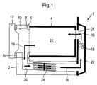
- FIG 1 illustrates a household appliance designed as a tumble drier 1 in a schematic illustration according to a first embodiment.
- the tumble drier 1 comprises a drum 4 mounted to rotate in a drier housing 2.
- a - in Figure 1 - left front side of the drum 4 is designed to be opened, so that the drum 4 may, for instance, be charged and discharged with laundry via this front side.
- a left annular front face 6 of the drum 4 is sealed against the drier housing 2 via a drum seal 8.
- the drier housing 2 comprises also a cylindrical opening 10, the diameter of which corresponds roughly to that of the drum 4.
- the opening 10 is adapted to be closed by a drier door 12, wherein the drier door 12 in the closed state abuts in a sealing manner on the drier housing 2 via a door seal 14.
- a process air indicated in Figure 1 with arrows 16 circulates in a closed circuit.
- the circuit comprises a heater 18 for heating the process air 16, wherein it is arranged, in Figure 1 , at the right of the drum 4 in the drier housing 2.
- the heater 18 is shielded from the environment by a heater cover 20.
- a supply and discharge channel for the process air 16 is additionally formed.
- process air 16 heated by the heater 18 gets, via openings formed in the - in Figure 1 - right front side of the drum 4, into a useful area 22 of the drum 4 in which, for instance, laundry to be dried is accommodated.
- a condenser unit 24 is arranged in the circuit of the process air 16. It is illustrated in a strongly simplified manner in Figure 1 and will be explained in more detail in the following Figures.
- the condenser unit 24 is arranged in an air passage 26 in Figure 1 below the drum 4.
- the air passage 26 is, at its left end portion, via a radial passage in communication with the opening 10 of the drier housing 2 and thus with the drum 4. Via its right end portion the air passage 26 is connected with the heater cover 20.
- a process air flow is generated by an impeller (not illustrated), so that the process air 16 then circulates in the circuit from the drum 4 via the condenser unit 24 arranged in the air passage 26, the heater 18 arranged in the heater cover 20, and back to the drum 4.
- the process air 16 For drying, for instance, humid laundry in the drum 4, the process air 16 is heated by the heater 18, so that the relative air humidity of the process air 16 decreases.
- the dry-hot process air 16 is routed through the humid laundry circulated in the drum 4 and absorbs its humidity by evaporation.
- the humid-hot process air 16 is subsequently cooled by the condenser unit 24 designed as an air/air heat exchanger.
- the condenser unit 24 designed as an air/air heat exchanger.
- the dew point temperature thereof is undercut, so that humidity condenses out of the process air as water.
- This water is collected by appliances, for instance, a sump (not illustrated), or is discharged.
- the dry-cool process air 16 is again supplied to the heater 18 for heating.
- FIG 2 shows in an enlarged illustration the condenser unit 24 of Figure 1 .
- the condenser unit 24 comprises four cooling layers 28, 30, 32, and 34 spaced apart in parallel.
- Each cooling layer 28 to 34 comprises a plurality of finned channels 36 having a roughly rectangular cross-section and pointing into the drawing plane in Figure 2 . They are adapted to be flown through by an ambient air that is referred to as cooling air in the following for cooling the process air 16.
- the cooling layers 28 and 30 jointly confine a bottom air passage 38, the middle cooling layers 30 and 32 an air passage 40, and the cooling layers 32 and 34 a top air passage 42, wherein the passages 38 to 42 are adapted to be flown through by the process air 16 approximately perpendicularly to the cooling air.
- the cooling layers 28 to 34 consist of aluminum having a good heat conduction.
- the middle cooling layers 30, 32 in Figure 2 are each adapted to be circulated around by the process air 16 from their top and bottom cooling faces 44 or 46, respectively.
- the top cooling layer 34 in Figure 2 adjoins to the air passage 42 with its bottom cooling face 46 only, and the bottom cooling layer 28 adjoins to the air passage 38 with its top cooling face 44.
- the humid-hot process air 16 gets through condenser unit 24 and is cooled by it.
- the process air 16 flows through the air passages 38 to 42 and gives off heat to the cooling air flowing through the cooling layers 28 to 34 approximately perpendicularly to the process air 16 and spatially separated therefrom.
- the cooling layers 28 to 34 are inclined such that condensed liquid or water 48 may flow off approximately in flow direction of the process air 16 along the cooling faces 44 of the cooling layers 28 to 32 to a central sump 50 and to a sump 52 positioned at the end of the condenser unit 24.
- the individual cooling layers 28 to 34 are each divided by a thermal insulator 54 approximately in the center into a left and a right cooling layer section in Figure 2 .
- the insulators 54 comprise openings so that condensed liquid 48 may flow off across them to the sump 50.
- Left cooling sections 56 and 58 of the two middle cooling layers 30 or 32, respectively, in Figure 2 each comprise thermoelectric heat pumps 60, 62 that are arranged approximately in the center. These are sandwiched conventional Peltier elements used for cooling the process air 16 and/or the condenser unit 24.
- the Peltier element is an electrothermic converter generating a temperature difference based on the Peltier effect if current flows through it.
- the heat pumps 60, 62 completely extend through the cooling layers 30 and 32 in the direction of the drawing plane in the embodiment.
- Heat pipes 64, 66 are provided for discharging a waste heat of the heat pumps 60, 62.
- Such heat pipes 64, 66 are sufficiently known from prior art. They are heat transmitters enabling a high heat flow density by utilizing the evaporation heat of a substance, i.e. large amounts of heat can be transported on a small cross sectional area.
- the heat pipes 64, 66 discharge the waste heat of the heat pumps 60, 62 and route it to right cooling sections 68 and 70 of the middle cooling layers 30 and 32 in Figure 2 .
- the left and right cooling sections 56, 58 or 68, 70, respectively, of the cooling layers 28 to 34 of the condenser unit 24 may also be designed as two condensers arranged in series.
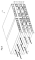
- FIG 3 shows the condenser unit 24 of Figure 2 in a perspective illustration.
- the spatial extension of the cooling layers 28 to 34 is illustrated here.
- the heat pumps 60 and 62 each extend completely through the respective cooling layer 30 and 32.
- a breadth of the heat pump 60 and 62 measured approximately in the direction of the flow of the process air 16 corresponds roughly to a third of the breadth of a respective left cooling section 56 or 58 of the cooling layers 32 or 30, respectively.
- a pipe section (not illustrated) of the heat pipes 64 completely extends through the sandwiched arrangement of the heat pumps 60 or 62, respectively, in the longitudinal direction thereof approximately in the center.
- a U-shaped outer pipe section 72 and 74 of the heat pipes 64 or 66, respectively, extends, spaced away from the heat pumps 60 and 62, to the condenser unit 24 along the cooling layers 30 or 32, respectively, up to the right cooling sections 68 and 70 of the cooling layers 30 or 32, respectively. Subsequently, the heat pipes 64 and 66 completely extend through the right cooling sections 68 and 70 with a pipe section (not illustrated) roughly in the direction transversely to the flow direction of the process air 16.
- the pipe sections (not illustrated) are arranged approximately centrally of the cooling sections 68, 70.
- the U-shaped outer pipe sections 72, 74 of the heat pipes 64, 66 are preferably thermally insulated.
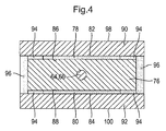
- thermoelectric heat pump 60 or 62 respectively, of Figure 3 is illustrated in a schematic cross sectional view.
- the heat pumps 60, 62 comprise a heat sink 76 consisting preferably of aluminum and having a roughly rectangular cross section.
- Peltier elements 78, 80 each is arranged which are adapted to be supplied with current via electrical connections that are not illustrated.
- the breadth of the Peltier elements 78 and 80 is somewhat smaller than that of the heat sink 76, and the Peltier elements 78, 80 are arranged approximately centrally with respect to the heat sink 76.
- a heat spreader 90 or 92, respectively, having a rectangular cross section abuts roughly on a respective cool side 82 or 84 of the Peltier elements 78 or 80, respectively.
- a vertical strength of a respective heat spreader 90 and 92 in Figure 5 corresponds approximately to half the strength of the heat sink 76.
- a breadth of the heat spreaders 90, 92 is somewhat larger than the breadth of the heat sink 76.
- Insulation elements 94 are arranged between the heat sink 76 and the respective heat spreader 90 and 92 next to the Peltier element 78 or 80, respectively.
- Insulation elements 96 are arranged between the heat spreaders 90 and 92.
- a left and a right side face of the heat sink 76 is thermally insulated from the environment by the insulation elements 96.
- the heat pumps 60, 62 are integrated such into the cooling layers 30 or 32, respectively, in Figure 2 that cooling faces 98, 100 of the heat spreader 90 or 92, respectively, facing away from the heat sink 76 of Figure 5 form an approximately plane face together with the cooling faces 44 or 46, respectively, of the cooling layers 30 or 32, respectively.
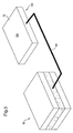
- Figure 5 shows in a perspective illustration the heat pump 60 together with the heat pipe 64 and a heat spreader 102 of Figure 3 .
- An end section (not illustrated) of the heat pipe 64 extends through the heat spreader 102 approximately centrally. It is designed such that its top and bottom spreader faces 104 and 106 in Figure 5 form an approximately plane face together with the top and bottom cooling faces 44 and 46 of the cooling layer 30 of Figure 2 .
- thermoelectric heat pumps 60, 62 of Figure 3 serve to cool the condenser unit 24 and/or the process air 16.
- Peltier elements 78, 80 of Figure 4 are supplied with current, so that their cool sides 82, 84 are cooled and their hot sides 86, 88 are heated.
- a temperature gradient is produced between the heat spreaders 90, 92 and the heat sink 76 positioned therebetween. Heat is absorbed from the process air 16 and the cooling layers 30, 32 of the condenser unit 24 in particular via the cooling faces 98 and 100 from the respective heat spreader 90 or 92, respectively.
- the waste heat of the Peltier elements 78, 80 is routed via the respective hot sides 86 and 88 to the heat sink 76 and is discharged via the heat pipe 64 and supplied to the heat spreaders 102, see Figure 3 . These then give the waste heat off to the right section of the condenser unit 24 in Figure 3 .
- the cooled and dried process air 16 is heated again, which serves as an efficient pre-heating of the process air 16 prior to the supplying to the heater 18 of Figure 1 .
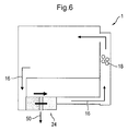
- thermoelectric pumps 60, 62 In order that the tumble drier 1 of Figure 1 is used in an energy-efficient manner it is advantageous to use the thermoelectric pumps 60, 62 at the beginning of a drying cycle since the condenser unit 24 is still warm and thus the process air 16 is cooled only insufficiently by the cooling air alone. By means of the thermoelectric heat pumps 60, 62 it is thus possible to perform an efficient cooling of the process air 16 even at the beginning of a drying cycle of the tumble drier 1. This will be explained in detail by means of Figures 6 and 7 .
- FIGs 6 and 7 show a simplified illustration of the tumble drier 1 of Figure 1 .
- Figure 6 illustrates the state of the tumble drier 1 at the beginning of a drying cycle.
- a blower for the cooling air of the condenser unit 24 is switched off, so that no warm ambient air flows through the condenser unit 24. This is referred to as "mode 1 ".
- the process air 16 is thus merely cooled via the thermoelectric heat pumps 60, 62 of Figure 3 .
- the cooling is hence performed in the left section of the condenser unit 24, so that condensed liquid or water, respectively, exits substantially from the middle sump 50.
- the cooled process air 16 is then heated again in the right section of the condenser unit 24 by the heat recovery of the heat pumps 60, 62 via the heat pipes 64, 66.
- the preheated process air 16 is then continued to be heated by the heater 18.
- the energy required by the heater 18 for heating the process air 16 is substantially smaller.
- FIG 7 shows a "mode 2" in which the thermoelectric heat pumps 60, 62 of Figure 3 are switched off and a blower 108 for supplying cooling air to the condenser unit 24 is switched on.
- the tumble drier 1 is conventionally operated in this "mode 2". Condensed liquid then exits at both sumps 50, 52.
- Figure 8 shows a second embodiment of the tumble drier 1 in a schematic illustration.
- two blowers 110, 112 are provided here.
- the first blower 110 positioned at the left in Figure 8 serves to supply cooling air to the left section of the condenser unit 24 and the second, right blower 112 to supply cooling air to the right section of the condenser unit 24.
- "mode 1" it is possible during "mode 1" to additionally cool the right section of the condenser unit 24 independently of the left section by the cooling air. This is either performed over the entire operating time of "mode 1" or, for instance, at the end of the operating time so as to pre-cool the right section of the condenser unit 24 when switching into "mode 2".
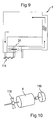
- FIG 9 shows a third embodiment of the tumble drier 1 in a schematic illustration.
- a blower like in the first embodiment is arranged, wherein, however, an electromechanical shutter 114 is provided.
- This electromechanical shutter 114 is adapted to initiate and terminate a cooling air flow to the left section of the condenser unit 24, see also Figure 2 .
- the shutter 114 is closed in the "mode 1", so that, in correspondence with Figure 8 , only the right section of the condenser unit 24 can be supplied with cooling air.
- the blower (not illustrated) may then be in continuous operation for both modes 1 and 2, for instance.
- Figure 10 shows a coupling of an impeller 116 for building up a process air flow, of a blower 118 for the cooling air of the condenser unit 24 of Figure 9 , and of the drum 4. This serves to illustrate that the impeller 116 and the blower 118 in the tumble drier 1 of Figure 9 are simply coupled with a drive for the drum 4.
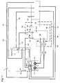
- FIG 11 shows in a simplified wiring diagram a current supply and a control of the tumble drier 1 of Figure 8 pursuant to the second embodiment.
- a power supply 120 the heater 18, the thermoelectric heat pumps 60, 62, the condenser unit 24, and the blowers 110, 112 are electrically connected via electric lines 122, 124, 126 or 128, respectively.
- an electric switch 130 to 136 is arranged to switch the current supply to the connected elements on and off.
- a control unit 138 is provided which is, via control lines 140, 142, 144, and 146, connected with a respective switch 130, 132, 134, and 136 for the control thereof.
- the control unit 138 furthermore comprises a plurality of measurement inputs.
- One measurement input is connected via a measuring line 148 with a sensor for measuring an ambient air temperature.
- Another measurement input is connected via a measuring line 150 with a sensor for measuring a post heater temperature and humidity, said sensor being positioned downstream of the heater 18 in flow direction of the process air 16.
- the control unit 148 is connected with a sensor that is positioned upstream of the heater 18 in flow direction of the process air 16 and that measures the pre-heater temperature and the humidity in this region.
- a sensor is connected with the control unit 138, said sensor measuring the temperature and humidity of the process air 16 before entering the condenser unit 24.
- the temperatures of the condenser unit 24 are measured, wherein a sensor is arranged in the left section, see also Figure 3 , of the condenser unit 24 and is connected with the control unit 138 via a measuring line 156.
- a sensor arranged in the right section of the condenser unit 24 is connected to the control unit 138 via a measuring line 158.
- blowers 110, 112 the thermoelectric heat pumps 60, 62, the condenser unit 24, and the heater 18 are then controlled as a function of the values measured by the sensors.
- a household appliance in particular a tumble drier, comprising a drying device for drying a process air routed in a circuit and discharged from a useful area, in particular a drier drum.
- the household appliance further comprises a heating device for heating the process air supplied to the useful area.
- the drying device comprises a condenser.
- the condenser comprises a thermoelectric heat pump, in particular a Peltier element, for cooling the condenser and/or the process air.
Landscapes
- Engineering & Computer Science (AREA)
- Textile Engineering (AREA)
- Drying Of Solid Materials (AREA)
- Detail Structures Of Washing Machines And Dryers (AREA)
Description
- The invention relates to a condenser unit in accordance with the preamble of
claim 1, a household appliance and a method for controlling such a household appliance. - Tumble driers are substantially according to an exhaust air principle or a condensation principle. In the case of an exhaust air principle, an air flow sucked in from the ambiance is heated and routed into a drier drum of the tumble drier containing laundry to be dried. Humidity is absorbed by the heated air flow and is subsequently returned to the ambiance.
- A well-known washing machine with an integrated drier is used in accordance with the condensation principle. Air sucked in from the ambiance is heated and routed via the drier drum to a heat exchanger where the air moistened in the drier drum is dried. The tumble drier comprises Peltier elements, wherein the supply air is heated at a hot side of the Peltier elements and the exhaust air is cooled at an opposite cold side of the Peltier elements.
-
DE 6 926 182 U - Document
DE 201 01 641 U1 discloses a tumble drier pursuant to the condensation principle, in the closed circuit of which the process air is cooled and heated again by means of Peltier elements. Additionally, the tumble drier comprises an air/air heat exchanger that continues to cool the air pre-cooled by the Peltier elements. Furthermore, an electric heating element is provided which continues to heat the process air heated by the Peltier elements. -
DE 10 2005 060 673 A1 also shows a tumble drier used in accordance with the condensation principle, in which the process air is, in a circuit, first of all routed past the cold side and subsequently past the hot side of Peltier elements. The Peltier elements are arranged in a module insulated at its hot side from the adjacent air line by an air and vapor-permeable filter. - In
document DE 10 2006 003 816 A1 another tumble drier with Peltier elements pursuant to the condensation principle is illustrated. These Peltier elements first of all withdraw in a closed circuit humidity from the process air by cooling it under the dew point and subsequently heat it again. To improve the heat pump performance of the Peltier elements arranged in series, the heat pump performance of the individual Peltier elements is adapted to the temperature difference to the process air. - Document
US 2007/0101602 A1 discloses a tumble drier with Peltier elements which are used substantially for cooling the process air routed out of the drier drum. Furthermore, embodiments are shown in which Peltier elements are used for the cooling and subsequent heating of the process air. -
JP 08057194 A -
WO 2007/068588 A1 discloses a tumble drier with a closed circuit in which Peltier elements are arranged. -
WO 2010/003936 A1 illustrates a heat pump type drier with an evaporator and a condenser. A heat pipe is used for cooling a compressor. -
DE 10 2004 055 926 A1 -
JP S 63017325 - It is an object of the invention to provide a more energy-efficient household appliance, a more energy-efficient condenser unit, and a method for controlling such a household appliance.
- This object is solved by a condenser unit pursuant to the features of
claim 1, by a household appliance pursuant to the features ofclaim 2, and by a method pursuant to the features ofclaim 12. - In accordance with the invention, a household appliance, in particular a tumble drier, comprises a drying device for drying a process air routed in a circuit and discharged from a useful area, in particular a drier drum. Furthermore, a heating device for heating the process air supplied to the useful area is provided in the circuit. The drying device comprises a condenser that is designed in particular as an air/air heat exchanger. It comprises a thermoelectric heat pump constructed with at least two Peltier elements, the thermoelectric heat pump serving to cool the condenser and/or the process air.
- This solution has the advantage that such a drying device is constructed in an energy-efficient and compact manner. Thus, it is possible to make use of the thermoelectric heat pump in particular in the initial phase of the drying process. In this initial phase, the temperature difference between the condenser and the process air is small, so that the drying of the process air is insufficient. By means of the thermoelectric heat pump it is possible to additionally cool the condenser strongly in the initial phase, so that the temperature difference between the process air and the condenser is very large, which results in an effective and energy-efficient drying of the process air. The tumble drier then operates extremely effectively even in the initial phase and the total drying time may be shortened, which results in a low energy consumption.
- For the easy discharge of waste heat of the heat pump, a heat pipe is provided.
- Preferably, the waste heat of the heat pump is supplied to the process air via the heat pipe downstream of the heat pump viewed in the direction of a process air flow. The waste heat may be supplied to the process air by the heat pipe with little effort with respect to device technology at any position in the circuit, which enables a simple and flexible construction of the tumble drier with respect to device technology.
- The condenser advantageously comprises at least one cooling layer that is adapted to be flown through by a cooling air and that is circulated around by the process air for cooling the process air. It is arranged such that condensed liquid flows off across it to a sump.
- Preferably, one section of the cooling layer forms the heat pump.
- In addition to the cooling layer, further cooling layers, in particular, for example, parallel cooling layers, with or without heat pump may be provided, which are arranged such that condensed liquid is adapted to flow off across them to a sump.
- In a further embodiment of the invention a second condenser is provided. It is arranged in series with the condenser comprising the heat pump, downstream thereof viewed in the direction of the process air. The condensers are thermally connected with each other via the heat pipe.
- The condensers may be designed as a condenser unit, wherein a sump for the flowing off of condensed liquid may be provided after each condenser.
- The heat pump is constructed in an extremely compact sandwiched manner with at least two Peltier elements. The hot sides thereof are then positioned opposite each other and the respective cool side faces in the direction of a respective cooling face of the cooling layer.
- A pipe section of the heat pipe for discharging the heat is positioned in particular approximately centrally between the hot sides of the Peltier elements.
- Preferably, the cool sides of the Peltier elements form each a section of the cooling face of the cooling layer of the condenser via heat spreaders. This makes it possible to form a large cooling face, in particular for cooling a process air flowing by, by means of comparatively small Peltier elements.
- To create a low heat resistance between the Peltier elements and the heat pipe, a heat sink, especially of aluminum, extended through by the pipe section of the heat pipe may be arranged between the hot sides of the heat pump.
- In order that the heat pipe is capable of effectively giving off the waste heat of the heat pump to the second condenser, a further pipe section is inserted in the cooling layer of the second condenser, in particular in a heat spreader forming a section of the cooling layer.
- Advantageously, the condensers are adapted to be flown through by the cooling air independently of each other. Thus, it is conceivable that the first condenser is not flown through by the cooling air in the initial phase of the drying process so as to achieve a quicker cooling of the condenser.
- In a further advantageous embodiment of the invention, a cooling air flow of the first condenser can be controlled via a control device, in particular a cover device. Alternatively, each condenser may be allocated a blower for controlling the cooling air flow which may be used independently of each other.
- In accordance with the invention, a thermoelectric heat pump for a household appliance, in particular for a tumble drier, comprises a heat pump for discharging the waste heat. By means of the heat pipe it is possible to supply the waste heat in a flexible manner at some other position in the household appliance in particular to the process air. In the initially explained state of the art, for instance, in
DE 201 01 641 U1 , it is necessary for supplying the waste air of the thermoelectric pump to the process air that the thermoelectric heat pump is arranged between a supply and an outlet channel. By means of the heat pipe it is thus no longer necessary to supply the waste heat to the process air directly in the region of the thermoelectric heat pump. - In accordance with the invention, a condenser unit, in particular for a household appliance, in particular for a tumble drier, comprises a first and preferably a second condenser. These are arranged in series in the direction of a process air flow. The first condenser that is arranged in the direction upstream of the process air flow on a higher level than the second condenser comprises a thermoelectric heat pump for cooling the condenser and/or a process air. A waste heat of the thermoelectric heat pump is supplied to the second condenser via a heat pipe for heating the process air. Such a condenser unit may be used in an extremely energy-efficient manner, wherein in particular in the initial phase of a drying process the first condenser is cooled additionally by the heat pump, or the heat pump in this phase exclusively serves to cool the process air.
- In accordance with the invention, a method for controlling a household appliance comprises the following steps:
- a) Switching on the thermoelectric heat pump in an initial phase of a drying process of the household appliance;
- b) switching off the thermoelectric heat pump after a predetermined period or at a predetermined temperature of the process air;
- c) switching on the cooling air flow through the second condenser and/or through the first condenser.
- The last step may also be performed prior to step a) or, for instance, simultaneously with step a), or between step a) and step b).
- Advantageous further developments of the invention are the subject matter of further subclaims.
- In the following, preferred embodiments of the invention will be explained in more detail by means of schematic drawings. The Figures show:
-
Figure 1 in a schematic illustration a tumble drier in accordance with a first embodiment; -
Figure 2 in a schematic illustration a condenser of the tumble drier ofFigure 1 ; -
Figure 3 in a perspective illustration the condenser ofFigure 2 ; -
Figure 4 in a side view a thermoelectric heat pump of the condenser ofFigure 2 ; -
Figure 5 in a perspective illustration the thermoelectric heat pump along with a heat pipe of the condenser; -
Figure 6 in a schematic illustration the tumble drier according to the first embodiment; -
Figure 7 in a schematic illustration the tumble drier according to the first embodiment; -
Figure 8 in a schematic illustration the tumble drier according to a second embodiment; -
Figure 9 in a schematic illustration the tumble drier according to a third embodiment; -
Figure 10 in a perspective illustration drive elements of the tumble drier; and -
Figure 11 a wiring diagram of the tumble drier according to the second embodiment. -
Figure 1 illustrates a household appliance designed as a tumble drier 1 in a schematic illustration according to a first embodiment. The tumble drier 1 comprises adrum 4 mounted to rotate in adrier housing 2. A - inFigure 1 - left front side of thedrum 4 is designed to be opened, so that thedrum 4 may, for instance, be charged and discharged with laundry via this front side. A left annularfront face 6 of thedrum 4 is sealed against thedrier housing 2 via adrum seal 8. For charging and discharging of thedrum 4, thedrier housing 2 comprises also acylindrical opening 10, the diameter of which corresponds roughly to that of thedrum 4. Theopening 10 is adapted to be closed by adrier door 12, wherein thedrier door 12 in the closed state abuts in a sealing manner on thedrier housing 2 via adoor seal 14. - For the drying of, for instance, humid laundry, a process air indicated in
Figure 1 witharrows 16 circulates in a closed circuit. The circuit comprises aheater 18 for heating theprocess air 16, wherein it is arranged, inFigure 1 , at the right of thedrum 4 in thedrier housing 2. Theheater 18 is shielded from the environment by aheater cover 20. Along with theheater cover 20, a supply and discharge channel for theprocess air 16 is additionally formed. Via aheater opening 21 arranged inFigure 1 in the region of thedrum 4,process air 16 heated by theheater 18 gets, via openings formed in the - inFigure 1 - right front side of thedrum 4, into auseful area 22 of thedrum 4 in which, for instance, laundry to be dried is accommodated. - For cooling the
process air 16, acondenser unit 24 according to the invention is arranged in the circuit of theprocess air 16. It is illustrated in a strongly simplified manner inFigure 1 and will be explained in more detail in the following Figures. Thecondenser unit 24 is arranged in anair passage 26 inFigure 1 below thedrum 4. Theair passage 26 is, at its left end portion, via a radial passage in communication with theopening 10 of thedrier housing 2 and thus with thedrum 4. Via its right end portion theair passage 26 is connected with theheater cover 20. A process air flow is generated by an impeller (not illustrated), so that theprocess air 16 then circulates in the circuit from thedrum 4 via thecondenser unit 24 arranged in theair passage 26, theheater 18 arranged in theheater cover 20, and back to thedrum 4. - For drying, for instance, humid laundry in the
drum 4, theprocess air 16 is heated by theheater 18, so that the relative air humidity of theprocess air 16 decreases. The dry-hot process air 16 is routed through the humid laundry circulated in thedrum 4 and absorbs its humidity by evaporation. The humid-hot process air 16 is subsequently cooled by thecondenser unit 24 designed as an air/air heat exchanger. By the cooling of theprocess air 16 via thecondenser unit 24, the dew point temperature thereof is undercut, so that humidity condenses out of the process air as water. This water is collected by appliances, for instance, a sump (not illustrated), or is discharged. Subsequently, the dry-cool process air 16 is again supplied to theheater 18 for heating. -
Figure 2 shows in an enlarged illustration thecondenser unit 24 ofFigure 1 . Thecondenser unit 24 comprises four coolinglayers cooling layer 28 to 34 comprises a plurality of finnedchannels 36 having a roughly rectangular cross-section and pointing into the drawing plane inFigure 2 . They are adapted to be flown through by an ambient air that is referred to as cooling air in the following for cooling theprocess air 16. - The cooling layers 28 and 30 jointly confine a
bottom air passage 38, the middle cooling layers 30 and 32 anair passage 40, and the cooling layers 32 and 34 atop air passage 42, wherein thepassages 38 to 42 are adapted to be flown through by theprocess air 16 approximately perpendicularly to the cooling air. The cooling layers 28 to 34 consist of aluminum having a good heat conduction. The middle cooling layers 30, 32 inFigure 2 are each adapted to be circulated around by theprocess air 16 from their top and bottom cooling faces 44 or 46, respectively. Thetop cooling layer 34 inFigure 2 adjoins to theair passage 42 with itsbottom cooling face 46 only, and thebottom cooling layer 28 adjoins to theair passage 38 with itstop cooling face 44. - In operation of the tumble drier 1 of
Figure 1 , the humid-hot process air 16 gets throughcondenser unit 24 and is cooled by it. Theprocess air 16 flows through theair passages 38 to 42 and gives off heat to the cooling air flowing through the cooling layers 28 to 34 approximately perpendicularly to theprocess air 16 and spatially separated therefrom. The cooling layers 28 to 34 are inclined such that condensed liquid orwater 48 may flow off approximately in flow direction of theprocess air 16 along the cooling faces 44 of the cooling layers 28 to 32 to acentral sump 50 and to asump 52 positioned at the end of thecondenser unit 24. - The individual cooling layers 28 to 34 are each divided by a
thermal insulator 54 approximately in the center into a left and a right cooling layer section inFigure 2 . Theinsulators 54 comprise openings so that condensed liquid 48 may flow off across them to thesump 50. -
Left cooling sections Figure 2 each comprisethermoelectric heat pumps process air 16 and/or thecondenser unit 24. The Peltier element is an electrothermic converter generating a temperature difference based on the Peltier effect if current flows through it. - The heat pumps 60, 62 completely extend through the cooling layers 30 and 32 in the direction of the drawing plane in the embodiment.
Heat pipes heat pumps Such heat pipes heat pipes heat pumps right cooling sections Figure 2 . - The left and
right cooling sections condenser unit 24 may also be designed as two condensers arranged in series. -
Figure 3 shows thecondenser unit 24 ofFigure 2 in a perspective illustration. The spatial extension of the cooling layers 28 to 34 is illustrated here. The heat pumps 60 and 62 each extend completely through therespective cooling layer heat pump process air 16 corresponds roughly to a third of the breadth of a respectiveleft cooling section heat pipes 64 completely extends through the sandwiched arrangement of theheat pumps outer pipe section heat pipes heat pumps condenser unit 24 along the cooling layers 30 or 32, respectively, up to theright cooling sections heat pipes right cooling sections process air 16. The pipe sections (not illustrated) are arranged approximately centrally of the coolingsections outer pipe sections heat pipes - In
Figure 4 , thethermoelectric heat pump Figure 3 is illustrated in a schematic cross sectional view. The heat pumps 60, 62 comprise aheat sink 76 consisting preferably of aluminum and having a roughly rectangular cross section. On the top and bottom faces of theheat sink 76,Peltier elements cool side Peltier elements heat sink 76 while ahot side Peltier elements heat sink 76. The breadth of thePeltier elements heat sink 76, and thePeltier elements heat sink 76. Aheat spreader cool side Peltier elements respective heat spreader Figure 5 corresponds approximately to half the strength of theheat sink 76. A breadth of theheat spreaders heat sink 76.Insulation elements 94 are arranged between theheat sink 76 and therespective heat spreader Peltier element Further Insulation elements 96 are arranged between theheat spreaders heat sink 76 is thermally insulated from the environment by theinsulation elements 96. The pipe section of theheat pipe heat sink 76 approximately centrally. - The heat pumps 60, 62 are integrated such into the cooling layers 30 or 32, respectively, in
Figure 2 that cooling faces 98, 100 of theheat spreader heat sink 76 ofFigure 5 form an approximately plane face together with the cooling faces 44 or 46, respectively, of the cooling layers 30 or 32, respectively. -
Figure 5 shows in a perspective illustration theheat pump 60 together with theheat pipe 64 and aheat spreader 102 ofFigure 3 . An end section (not illustrated) of theheat pipe 64 extends through theheat spreader 102 approximately centrally. It is designed such that its top and bottom spreader faces 104 and 106 inFigure 5 form an approximately plane face together with the top and bottom cooling faces 44 and 46 of thecooling layer 30 ofFigure 2 . - In the following, the functioning of the
condenser unit 24 will be explained in detail by means ofFigures 2 to 5 . - The
thermoelectric heat pumps Figure 3 serve to cool thecondenser unit 24 and/or theprocess air 16. To this end,Peltier elements Figure 4 are supplied with current, so that theircool sides hot sides heat spreaders heat sink 76 positioned therebetween. Heat is absorbed from theprocess air 16 and the cooling layers 30, 32 of thecondenser unit 24 in particular via the cooling faces 98 and 100 from therespective heat spreader Peltier elements hot sides heat sink 76 and is discharged via theheat pipe 64 and supplied to theheat spreaders 102, seeFigure 3 . These then give the waste heat off to the right section of thecondenser unit 24 inFigure 3 . Thus, the cooled and driedprocess air 16 is heated again, which serves as an efficient pre-heating of theprocess air 16 prior to the supplying to theheater 18 ofFigure 1 . - In order that the tumble drier 1 of
Figure 1 is used in an energy-efficient manner it is advantageous to use the thermoelectric pumps 60, 62 at the beginning of a drying cycle since thecondenser unit 24 is still warm and thus theprocess air 16 is cooled only insufficiently by the cooling air alone. By means of thethermoelectric heat pumps process air 16 even at the beginning of a drying cycle of the tumble drier 1. This will be explained in detail by means ofFigures 6 and7 . -
Figures 6 and7 show a simplified illustration of the tumble drier 1 ofFigure 1 .Figure 6 illustrates the state of the tumble drier 1 at the beginning of a drying cycle. A blower for the cooling air of thecondenser unit 24 is switched off, so that no warm ambient air flows through thecondenser unit 24. This is referred to as "mode 1 ". Theprocess air 16 is thus merely cooled via thethermoelectric heat pumps Figure 3 . The cooling is hence performed in the left section of thecondenser unit 24, so that condensed liquid or water, respectively, exits substantially from themiddle sump 50. The cooledprocess air 16 is then heated again in the right section of thecondenser unit 24 by the heat recovery of theheat pumps heat pipes preheated process air 16 is then continued to be heated by theheater 18. By the pre-heating of theprocess air 16, the energy required by theheater 18 for heating theprocess air 16 is substantially smaller. -
Figure 7 shows a "mode 2" in which thethermoelectric heat pumps Figure 3 are switched off and ablower 108 for supplying cooling air to thecondenser unit 24 is switched on. The tumble drier 1 is conventionally operated in this "mode 2". Condensed liquid then exits at bothsumps -
Figure 8 shows a second embodiment of the tumble drier 1 in a schematic illustration. In contrast to the first embodiment ofFigures 1 to 7 , twoblowers first blower 110 positioned at the left inFigure 8 serves to supply cooling air to the left section of thecondenser unit 24 and the second,right blower 112 to supply cooling air to the right section of thecondenser unit 24. Thus, it is possible during "mode 1" to additionally cool the right section of thecondenser unit 24 independently of the left section by the cooling air. This is either performed over the entire operating time of "mode 1" or, for instance, at the end of the operating time so as to pre-cool the right section of thecondenser unit 24 when switching into "mode 2". -
Figure 9 shows a third embodiment of the tumble drier 1 in a schematic illustration. Instead of two blowers, seeFigure 8 , a blower (not illustrated) like in the first embodiment is arranged, wherein, however, anelectromechanical shutter 114 is provided. Thiselectromechanical shutter 114 is adapted to initiate and terminate a cooling air flow to the left section of thecondenser unit 24, see alsoFigure 2 . Thus, theshutter 114 is closed in the "mode 1", so that, in correspondence withFigure 8 , only the right section of thecondenser unit 24 can be supplied with cooling air. The blower (not illustrated) may then be in continuous operation for bothmodes -
Figure 10 shows a coupling of animpeller 116 for building up a process air flow, of ablower 118 for the cooling air of thecondenser unit 24 ofFigure 9 , and of thedrum 4. This serves to illustrate that theimpeller 116 and theblower 118 in the tumble drier 1 ofFigure 9 are simply coupled with a drive for thedrum 4. -
Figure 11 shows in a simplified wiring diagram a current supply and a control of the tumble drier 1 ofFigure 8 pursuant to the second embodiment. By apower supply 120, theheater 18, thethermoelectric heat pumps condenser unit 24, and theblowers electric lines electric line 122 to 128, anelectric switch 130 to 136 is arranged to switch the current supply to the connected elements on and off. In addition to thepower supply 120, acontrol unit 138 is provided which is, viacontrol lines respective switch - The
control unit 138 furthermore comprises a plurality of measurement inputs. One measurement input is connected via ameasuring line 148 with a sensor for measuring an ambient air temperature. Another measurement input is connected via ameasuring line 150 with a sensor for measuring a post heater temperature and humidity, said sensor being positioned downstream of theheater 18 in flow direction of theprocess air 16. Via ameasuring line 152, thecontrol unit 148 is connected with a sensor that is positioned upstream of theheater 18 in flow direction of theprocess air 16 and that measures the pre-heater temperature and the humidity in this region. Via themeasuring line 154, a sensor is connected with thecontrol unit 138, said sensor measuring the temperature and humidity of theprocess air 16 before entering thecondenser unit 24. Furthermore, the temperatures of thecondenser unit 24 are measured, wherein a sensor is arranged in the left section, see alsoFigure 3 , of thecondenser unit 24 and is connected with thecontrol unit 138 via ameasuring line 156. A sensor arranged in the right section of thecondenser unit 24 is connected to thecontrol unit 138 via ameasuring line 158. - The
blowers thermoelectric heat pumps condenser unit 24, and theheater 18 are then controlled as a function of the values measured by the sensors. - Disclosed is a household appliance, in particular a tumble drier, comprising a drying device for drying a process air routed in a circuit and discharged from a useful area, in particular a drier drum. The household appliance further comprises a heating device for heating the process air supplied to the useful area. The drying device comprises a condenser. The condenser comprises a thermoelectric heat pump, in particular a Peltier element, for cooling the condenser and/or the process air.
-
- 1
- tumble drier
- 2
- drier housing
- 4
- drum
- 6
- annular front face
- 8
- drum seal
- 10
- opening
- 12
- drier door
- 14
- door seal
- 16
- process air
- 18
- heater
- 20
- heater cover
- 21
- heater opening
- 22
- useful area
- 24
- condenser unit
- 26
- air passage
- 28
- cooling layer
- 30
- cooling layer
- 32
- cooling layer
- 34
- cooling layer
- 36
- finned channel
- 38
- bottom air passage
- 40
- middle air passage
- 42
- top air passage
- 44
- cooling face
- 46
- cooling face
- 48
- condensed liquid
- 50
- sump
- 52
- sump
- 54
- insulator
- 56
- cooling sections
- 58
- cooling sections
- 60
- heat pump
- 62
- heat pump
- 64
- heat pipe
- 66
- heat pipe
- 68
- cooling sections
- 70
- cooling sections
- 72
- pipe section
- 74
- pipe section
- 76
- heat sink
- 78
- Peltier element
- 80
- Peltier element
- 82
- cool side
- 84
- cool side
- 86
- hot side
- 88
- hot side
- 90
- heat spreader
- 92
- heat spreader
- 94
- insulation element
- 96
- insulation element
- 98
- cooling face
- 100
- cooling face
- 102
- heat spreader
- 104
- spreader face
- 106
- spreader face
- 108
- blower
- 110
- blower
- 112
- blower
- 114
- shutter
- 116
- impeller
- 118
- blower
- 120
- power supply
- 122
- line
- 124
- line
- 126
- line
- 128
- line
- 130
- switch
- 132
- switch
- 134
- switch
- 136
- switch
- 138
- control unit
- 140
- control line
- 142
- control line
- 144
- control line
- 146
- control line
- 148
- measuring line
- 150
- measuring line
- 152
- measuring line
- 154
- measuring line
- 156
- measuring line
- 158
- measuring line
Claims (12)
- A condenser unit comprising a thermoelectric heat pump (60, 62) that is arranged such that a first condenser (24) arranged in said condenser unit and/or a process air (16) are adapted to be cooled by said heat pump (60, 62) comprising a heat pipe (64, 66), whereby a waste heat of the heat pump (60, 62) is discharged via the heat pipe (64, 66), and wherein the heat pump (60, 62) is constructed with at least two Peltier elements (78, 80), the condenser unit further comprising at least one cooling layer (30, 32), characterized in that the hot sides (86, 88) of the Peltier elements (78, 80) are positioned opposite each other and facing each other and the respective cool sides (82, 84) in the direction of a respective cooling face (44, 46) of said cooling layer (30, 32), wherein a pipe section of the heat pipe (64, 66) for discharging the waste heat is positioned between the hot sides (86, 88) of the Peltier elements (78, 80).
- A household appliance, in particular a tumble drier, comprising a drying device for drying a process air (16) routed in a circuit and discharged from a useful area (22), in particular a drier drum (4), and a heater (18) for heating the process air (16) supplied to the useful area (22), characterized in that the drying device comprises a condenser unit according to claim 1, which is designed in particular as an air/air heat exchanger, whereby the thermoelectric heat pump (60, 62) is used for cooling said first condenser (24) and/or said process air (16), wherein the waste heat of said heat pump (60, 62) is supplied to said process air (16) via said heat pipe (64, 66).
- The household appliance according to claim 2, wherein said first condenser (24) comprises said at least one cooling layer (28, 30, 32, 34) adapted to be flown through by a cooling air and circulated around by said process air (16) for cooling said process air (16), said cooling layer (28, 30, 32, 34) being arranged such that condensed liquid flows off across it to a sump (50, 52).
- The household appliance according to claim 3, wherein a section of said cooling layer (28, 30, 32, 34) forms said heat pump (60, 62).
- The household appliance according to one or several of claims 2 to 4, wherein a second condenser (24) is provided in series to the first condenser (24) comprising the heat pump (60, 62) and downstream thereof viewed in the direction of the process air flow, said second condenser (24) being thermally connected with said first condenser (24) via said heat pipe (64, 66).
- The household appliance according to one or several of claims 3 to 5, wherein the pipe section of said heat pipe (64, 66) is positioned centrally between said hot sides (86, 88) for discharging the waste heat of said Peltier elements (78, 80).
- The household appliance according to one or several of claims 3 to 6, wherein said cool sides (82, 84) of said Peltier elements (78, 80) each form a section of said cooling face (44, 46) of said cooling layer (30, 32) of said condenser (24) via heat spreaders.
- The household appliance according to claims 6 or 7, wherein a heat sink (76), in particular of aluminum, extended through by the pipe section of said heat pipe (64, 66) is positioned between said hot sides (86, 88) of said Peltier elements (78, 80).
- The household appliance according to claim 5, wherein a further pipe section of said heat pipe (64, 66) extends through the cooling layer (30, 32), in particular a heat spreader (102) forming a section of said cooling layer (30, 32), of said second condenser (24).
- The household appliance according to claims 3 and 5, wherein said condensers (24) are adapted to be flown through by said cooling air independently of each other.
- The household appliance according to claim 10, wherein the process air flow of the first condenser (24) is adapted to be controlled via a control device (114), in particular a cover device, and/or wherein each condenser (24) is assigned with a blower for controlling the process air flow, which may be used independently of each other.
- A method for controlling a household appliance according to claim 5 or 9 or 10 or 11, comprising the steps of:a) switching on the thermoelectric heat pump (60, 62) in an initial phase of a drying process during operation of the household appliance;b) switching off the thermoelectric heat pump (60, 62) after a predetermined period or at a predetermined temperature of the process air (16);c) switching on the cooling air flow through the second condenser (24) and/or through the first condenser (24) prior to step a) or simultaneously with step a) or between step a) and b).
Priority Applications (1)
| Application Number | Priority Date | Filing Date | Title |
|---|---|---|---|
| EP10003480.0A EP2372012B1 (en) | 2010-03-30 | 2010-03-30 | Condenser unit, household appliance, and method for controlling such a household appliance |
Applications Claiming Priority (1)
| Application Number | Priority Date | Filing Date | Title |
|---|---|---|---|
| EP10003480.0A EP2372012B1 (en) | 2010-03-30 | 2010-03-30 | Condenser unit, household appliance, and method for controlling such a household appliance |
Publications (2)
| Publication Number | Publication Date |
|---|---|
| EP2372012A1 EP2372012A1 (en) | 2011-10-05 |
| EP2372012B1 true EP2372012B1 (en) | 2016-08-31 |
Family
ID=42732808
Family Applications (1)
| Application Number | Title | Priority Date | Filing Date |
|---|---|---|---|
| EP10003480.0A Not-in-force EP2372012B1 (en) | 2010-03-30 | 2010-03-30 | Condenser unit, household appliance, and method for controlling such a household appliance |
Country Status (1)
| Country | Link |
|---|---|
| EP (1) | EP2372012B1 (en) |
Cited By (3)
| Publication number | Priority date | Publication date | Assignee | Title |
|---|---|---|---|---|
| US11672404B2 (en) | 2020-10-07 | 2023-06-13 | Whirlpool Corporation | Dish treating appliance with an air supply circuit |
| US11802364B2 (en) | 2021-04-16 | 2023-10-31 | Whirlpool Corporation | Condensing system for combination washer/dryer appliance |
| US11952696B2 (en) | 2019-09-18 | 2024-04-09 | The Procter & Gamble Company | Combination washing and drying apparatuses including cooled water condensers |
Families Citing this family (12)
| Publication number | Priority date | Publication date | Assignee | Title |
|---|---|---|---|---|
| DK2578741T3 (en) * | 2011-10-04 | 2017-07-03 | Dbk David + Baader Gmbh | Thermoelectric heat pump, heat exchanger, home appliance and method of operating a home appliance |
| CN103842579B (en) * | 2011-10-07 | 2017-02-15 | 阿塞里克股份有限公司 | A laundry washing and drying machine comprising a condenser |
| CN104968853B (en) * | 2012-09-24 | 2017-05-03 | 阿塞里克股份有限公司 | A laundry washing and drying machine comprising a condenser |
| EP2796613B1 (en) * | 2013-04-23 | 2020-11-11 | Whirlpool Corporation | Dryer or washer dryer and method for its operation |
| WO2015127985A1 (en) * | 2014-02-28 | 2015-09-03 | Arcelik Anonim Sirketi | Laundry treatment machine condenser condensate water discharge line |
| KR102204615B1 (en) * | 2014-03-06 | 2021-01-19 | 엘지전자 주식회사 | Laundry Treating Apparatus |
| CN105734933B (en) * | 2014-12-12 | 2019-09-03 | 杭州三花研究院有限公司 | Drying system and clothes drying device |
| KR101792513B1 (en) * | 2015-06-11 | 2017-11-02 | 엘지전자 주식회사 | Heating cycle drying module of dishwasher using Fan module and PTC Heater |
| CN106580219B (en) * | 2015-10-19 | 2021-08-24 | 三花亚威科电器设备(芜湖)有限公司 | Dish washing machine |
| US10098520B2 (en) * | 2016-03-09 | 2018-10-16 | Whirlpool Corporation | Dishwasher with a multi-layer acoustic material in a condensing drying system |
| IT201700020866A1 (en) * | 2017-02-23 | 2018-08-23 | Chiriatti Antonio Francesco | Dryer for wool and delicate fabrics |
| EP3427631A1 (en) * | 2017-07-12 | 2019-01-16 | Miele & Cie. KG | Dishwasher with a heat pump circuit |
Citations (2)
| Publication number | Priority date | Publication date | Assignee | Title |
|---|---|---|---|---|
| JPS6317325A (en) * | 1986-07-10 | 1988-01-25 | Matsushita Electric Ind Co Ltd | dehumidifier |
| DE102004055926A1 (en) * | 2004-11-19 | 2006-05-24 | BSH Bosch und Siemens Hausgeräte GmbH | Drying unit for household appliances especially for textiles has heat tube between warm air region and using region |
Family Cites Families (13)
| Publication number | Priority date | Publication date | Assignee | Title |
|---|---|---|---|---|
| GB911433A (en) * | 1958-10-08 | 1962-11-28 | Gen Electric Co Ltd | Improvements in or relating to air conditioners |
| DE1410206A1 (en) | 1959-09-21 | 1968-10-10 | Siemens Elektrogeraete Gmbh | Washing machine |
| DE6926182U (en) | 1969-07-01 | 1969-12-04 | Christian Schneider | LAUNDRY DRYERS |
| JPH0857194A (en) | 1994-08-26 | 1996-03-05 | Matsushita Electric Ind Co Ltd | Dehumidification type electric clothes dryer |
| DE20101641U1 (en) | 2001-01-29 | 2002-06-06 | AKG-Thermotechnik GmbH & Co. KG, 34369 Hofgeismar | Condensation dryer and suitable condensation heat exchanger |
| US7526879B2 (en) | 2005-11-04 | 2009-05-05 | Lg Electronics Inc. | Drum washing machine and clothes dryer using peltier thermoelectric module |
| DE102005058285A1 (en) * | 2005-12-06 | 2007-06-14 | BSH Bosch und Siemens Hausgeräte GmbH | Device for drying laundry |
| DE102005060355A1 (en) * | 2005-12-16 | 2007-06-21 | BSH Bosch und Siemens Hausgeräte GmbH | Domestic appliance with thermoelectric heat pump |
| DE102005060673A1 (en) | 2005-12-19 | 2007-06-21 | BSH Bosch und Siemens Hausgeräte GmbH | Clothes dryer with Peltier heat pump |
| DE102006003816A1 (en) | 2006-01-26 | 2007-08-02 | BSH Bosch und Siemens Hausgeräte GmbH | Domestic appliance, e.g. washing dryer, with thermoelectric heat pump, has several Peltier elements located in axially varying distribution to improve utilization of individual outputs |
| DE602007004109D1 (en) * | 2006-05-31 | 2010-02-11 | Arcelik As | DISHWASHING MACHINE WITH IMPROVED DRY ARRANGEMENT |
| DE102006042991A1 (en) * | 2006-09-13 | 2008-03-27 | BSH Bosch und Siemens Hausgeräte GmbH | Apparatus and method for drying laundry with a heat pump and a heat exchanger |
| WO2010003936A1 (en) * | 2008-07-07 | 2010-01-14 | Arcelik Anonim Sirketi | A heat pump type dryer |
-
2010
- 2010-03-30 EP EP10003480.0A patent/EP2372012B1/en not_active Not-in-force
Patent Citations (2)
| Publication number | Priority date | Publication date | Assignee | Title |
|---|---|---|---|---|
| JPS6317325A (en) * | 1986-07-10 | 1988-01-25 | Matsushita Electric Ind Co Ltd | dehumidifier |
| DE102004055926A1 (en) * | 2004-11-19 | 2006-05-24 | BSH Bosch und Siemens Hausgeräte GmbH | Drying unit for household appliances especially for textiles has heat tube between warm air region and using region |
Cited By (4)
| Publication number | Priority date | Publication date | Assignee | Title |
|---|---|---|---|---|
| US11952696B2 (en) | 2019-09-18 | 2024-04-09 | The Procter & Gamble Company | Combination washing and drying apparatuses including cooled water condensers |
| US11672404B2 (en) | 2020-10-07 | 2023-06-13 | Whirlpool Corporation | Dish treating appliance with an air supply circuit |
| US12082762B2 (en) | 2020-10-07 | 2024-09-10 | Whirlpool Corporation | Dish treating appliance with an air supply circuit |
| US11802364B2 (en) | 2021-04-16 | 2023-10-31 | Whirlpool Corporation | Condensing system for combination washer/dryer appliance |
Also Published As
| Publication number | Publication date |
|---|---|
| EP2372012A1 (en) | 2011-10-05 |
Similar Documents
| Publication | Publication Date | Title |
|---|---|---|
| EP2372012B1 (en) | Condenser unit, household appliance, and method for controlling such a household appliance | |
| CN105671902B (en) | Condensing type clothes dryer and control method thereof | |
| EP3031976B1 (en) | Clothes treating apparatus with a heat pump system | |
| US10662575B2 (en) | Clothes dryer and method for controlling same | |
| DK2578741T3 (en) | Thermoelectric heat pump, heat exchanger, home appliance and method of operating a home appliance | |
| EP2489774A1 (en) | A heat pump laundry dryer | |
| EP2489775A1 (en) | A heat pump laundry dryer and a method for operating a heat pump laundry dryer | |
| US9146056B2 (en) | Laundry treating apparatus having expansion valve which is variable according to the driving mode | |
| US8356496B2 (en) | Apparatus and method for loading items to be washed with an air flow | |
| US20100083524A1 (en) | Apparatus and process for drying items of laundry, using a heat pump and a heat exchanger | |
| US20180371682A1 (en) | Clothes drying device and method for drying clothes | |
| EP3294943B1 (en) | Laundry treatment apparatus | |
| EP2722432B1 (en) | Clothes treating apparatus with heat pump and control method thereof | |
| EP2586905B1 (en) | A laundry dryer with a heat pump system | |
| US20090320319A1 (en) | Domestic Device For The Care of Laundry Items and Method for Passing Cooling Air Into Such a Device | |
| US20170328609A1 (en) | Caloric Heat Pump Dishwasher Appliance | |
| EP2312049B1 (en) | A tumble dryer with a heat pump system | |
| EP2594688B1 (en) | A laundry dryer with a heat pump system | |
| EP2650425B1 (en) | Laundry drying machine | |
| KR200453902Y1 (en) | Cold. Hot air cross dryer | |
| JP2011092510A (en) | Clothes dryer | |
| KR100640819B1 (en) | Clothes dryer with thermoelectric modular condenser | |
| EP2716811A1 (en) | A method for controlling the rotation speed of a laundry drum in a laundry dryer and a corresponding laundry dryer | |
| US20110041835A1 (en) | Solar heat exchanger | |
| EP2586907B1 (en) | A laundry dryer with a heat pump system and air recirculation |
Legal Events
| Date | Code | Title | Description |
|---|---|---|---|
| PUAI | Public reference made under article 153(3) epc to a published international application that has entered the european phase |
Free format text: ORIGINAL CODE: 0009012 |
|
| 17P | Request for examination filed |
Effective date: 20101125 |
|
| AK | Designated contracting states |
Kind code of ref document: A1 Designated state(s): AT BE BG CH CY CZ DE DK EE ES FI FR GB GR HR HU IE IS IT LI LT LU LV MC MK MT NL NO PL PT RO SE SI SK SM TR |
|
| AX | Request for extension of the european patent |
Extension state: AL BA ME RS |
|
| 17Q | First examination report despatched |
Effective date: 20130603 |
|
| RAP1 | Party data changed (applicant data changed or rights of an application transferred) |
Owner name: DBK DAVID + BAADER GMBH |
|
| GRAP | Despatch of communication of intention to grant a patent |
Free format text: ORIGINAL CODE: EPIDOSNIGR1 |
|
| RIC1 | Information provided on ipc code assigned before grant |
Ipc: D06F 58/24 20060101ALI20160225BHEP Ipc: D06F 58/28 20060101ALN20160225BHEP Ipc: A47L 15/48 20060101ALI20160225BHEP Ipc: D06F 58/20 20060101AFI20160225BHEP Ipc: A47L 15/00 20060101ALN20160225BHEP |
|
| INTG | Intention to grant announced |
Effective date: 20160315 |
|
| RIN1 | Information on inventor provided before grant (corrected) |
Inventor name: HOPKIN, IAN DAVID |
|
| GRAS | Grant fee paid |
Free format text: ORIGINAL CODE: EPIDOSNIGR3 |
|
| GRAA | (expected) grant |
Free format text: ORIGINAL CODE: 0009210 |
|
| RIN1 | Information on inventor provided before grant (corrected) |
Inventor name: HOPKIN, IAN DAVID DR. |
|
| AK | Designated contracting states |
Kind code of ref document: B1 Designated state(s): AT BE BG CH CY CZ DE DK EE ES FI FR GB GR HR HU IE IS IT LI LT LU LV MC MK MT NL NO PL PT RO SE SI SK SM TR |
|
| REG | Reference to a national code |
Ref country code: CH Ref legal event code: EP Ref country code: GB Ref legal event code: FG4D |
|
| REG | Reference to a national code |
Ref country code: IE Ref legal event code: FG4D |
|
| REG | Reference to a national code |
Ref country code: DE Ref legal event code: R096 Ref document number: 602010035922 Country of ref document: DE |
|
| REG | Reference to a national code |
Ref country code: AT Ref legal event code: REF Ref document number: 825077 Country of ref document: AT Kind code of ref document: T Effective date: 20161015 |
|
| REG | Reference to a national code |
Ref country code: LT Ref legal event code: MG4D |
|
| REG | Reference to a national code |
Ref country code: NL Ref legal event code: MP Effective date: 20160831 |
|
| REG | Reference to a national code |
Ref country code: AT Ref legal event code: MK05 Ref document number: 825077 Country of ref document: AT Kind code of ref document: T Effective date: 20160831 |
|
| PG25 | Lapsed in a contracting state [announced via postgrant information from national office to epo] |
Ref country code: LT Free format text: LAPSE BECAUSE OF FAILURE TO SUBMIT A TRANSLATION OF THE DESCRIPTION OR TO PAY THE FEE WITHIN THE PRESCRIBED TIME-LIMIT Effective date: 20160831 Ref country code: FI Free format text: LAPSE BECAUSE OF FAILURE TO SUBMIT A TRANSLATION OF THE DESCRIPTION OR TO PAY THE FEE WITHIN THE PRESCRIBED TIME-LIMIT Effective date: 20160831 Ref country code: HR Free format text: LAPSE BECAUSE OF FAILURE TO SUBMIT A TRANSLATION OF THE DESCRIPTION OR TO PAY THE FEE WITHIN THE PRESCRIBED TIME-LIMIT Effective date: 20160831 Ref country code: NO Free format text: LAPSE BECAUSE OF FAILURE TO SUBMIT A TRANSLATION OF THE DESCRIPTION OR TO PAY THE FEE WITHIN THE PRESCRIBED TIME-LIMIT Effective date: 20161130 |
|
| PG25 | Lapsed in a contracting state [announced via postgrant information from national office to epo] |
Ref country code: GR Free format text: LAPSE BECAUSE OF FAILURE TO SUBMIT A TRANSLATION OF THE DESCRIPTION OR TO PAY THE FEE WITHIN THE PRESCRIBED TIME-LIMIT Effective date: 20161201 Ref country code: NL Free format text: LAPSE BECAUSE OF FAILURE TO SUBMIT A TRANSLATION OF THE DESCRIPTION OR TO PAY THE FEE WITHIN THE PRESCRIBED TIME-LIMIT Effective date: 20160831 Ref country code: ES Free format text: LAPSE BECAUSE OF FAILURE TO SUBMIT A TRANSLATION OF THE DESCRIPTION OR TO PAY THE FEE WITHIN THE PRESCRIBED TIME-LIMIT Effective date: 20160831 Ref country code: LV Free format text: LAPSE BECAUSE OF FAILURE TO SUBMIT A TRANSLATION OF THE DESCRIPTION OR TO PAY THE FEE WITHIN THE PRESCRIBED TIME-LIMIT Effective date: 20160831 Ref country code: SE Free format text: LAPSE BECAUSE OF FAILURE TO SUBMIT A TRANSLATION OF THE DESCRIPTION OR TO PAY THE FEE WITHIN THE PRESCRIBED TIME-LIMIT Effective date: 20160831 Ref country code: AT Free format text: LAPSE BECAUSE OF FAILURE TO SUBMIT A TRANSLATION OF THE DESCRIPTION OR TO PAY THE FEE WITHIN THE PRESCRIBED TIME-LIMIT Effective date: 20160831 |
|
| REG | Reference to a national code |
Ref country code: FR Ref legal event code: PLFP Year of fee payment: 8 |
|
| PG25 | Lapsed in a contracting state [announced via postgrant information from national office to epo] |
Ref country code: RO Free format text: LAPSE BECAUSE OF FAILURE TO SUBMIT A TRANSLATION OF THE DESCRIPTION OR TO PAY THE FEE WITHIN THE PRESCRIBED TIME-LIMIT Effective date: 20160831 Ref country code: EE Free format text: LAPSE BECAUSE OF FAILURE TO SUBMIT A TRANSLATION OF THE DESCRIPTION OR TO PAY THE FEE WITHIN THE PRESCRIBED TIME-LIMIT Effective date: 20160831 |
|
| PG25 | Lapsed in a contracting state [announced via postgrant information from national office to epo] |
Ref country code: CZ Free format text: LAPSE BECAUSE OF FAILURE TO SUBMIT A TRANSLATION OF THE DESCRIPTION OR TO PAY THE FEE WITHIN THE PRESCRIBED TIME-LIMIT Effective date: 20160831 Ref country code: PT Free format text: LAPSE BECAUSE OF FAILURE TO SUBMIT A TRANSLATION OF THE DESCRIPTION OR TO PAY THE FEE WITHIN THE PRESCRIBED TIME-LIMIT Effective date: 20170102 Ref country code: BG Free format text: LAPSE BECAUSE OF FAILURE TO SUBMIT A TRANSLATION OF THE DESCRIPTION OR TO PAY THE FEE WITHIN THE PRESCRIBED TIME-LIMIT Effective date: 20161130 Ref country code: BE Free format text: LAPSE BECAUSE OF FAILURE TO SUBMIT A TRANSLATION OF THE DESCRIPTION OR TO PAY THE FEE WITHIN THE PRESCRIBED TIME-LIMIT Effective date: 20160831 Ref country code: DK Free format text: LAPSE BECAUSE OF FAILURE TO SUBMIT A TRANSLATION OF THE DESCRIPTION OR TO PAY THE FEE WITHIN THE PRESCRIBED TIME-LIMIT Effective date: 20160831 Ref country code: SM Free format text: LAPSE BECAUSE OF FAILURE TO SUBMIT A TRANSLATION OF THE DESCRIPTION OR TO PAY THE FEE WITHIN THE PRESCRIBED TIME-LIMIT Effective date: 20160831 Ref country code: PL Free format text: LAPSE BECAUSE OF FAILURE TO SUBMIT A TRANSLATION OF THE DESCRIPTION OR TO PAY THE FEE WITHIN THE PRESCRIBED TIME-LIMIT Effective date: 20160831 Ref country code: SK Free format text: LAPSE BECAUSE OF FAILURE TO SUBMIT A TRANSLATION OF THE DESCRIPTION OR TO PAY THE FEE WITHIN THE PRESCRIBED TIME-LIMIT Effective date: 20160831 |
|
| REG | Reference to a national code |
Ref country code: DE Ref legal event code: R097 Ref document number: 602010035922 Country of ref document: DE |
|
| PLBE | No opposition filed within time limit |
Free format text: ORIGINAL CODE: 0009261 |
|
| STAA | Information on the status of an ep patent application or granted ep patent |
Free format text: STATUS: NO OPPOSITION FILED WITHIN TIME LIMIT |
|
| 26N | No opposition filed |
Effective date: 20170601 |
|
| PG25 | Lapsed in a contracting state [announced via postgrant information from national office to epo] |
Ref country code: SI Free format text: LAPSE BECAUSE OF FAILURE TO SUBMIT A TRANSLATION OF THE DESCRIPTION OR TO PAY THE FEE WITHIN THE PRESCRIBED TIME-LIMIT Effective date: 20160831 |
|
| REG | Reference to a national code |
Ref country code: CH Ref legal event code: PL |
|
| PG25 | Lapsed in a contracting state [announced via postgrant information from national office to epo] |
Ref country code: MC Free format text: LAPSE BECAUSE OF FAILURE TO SUBMIT A TRANSLATION OF THE DESCRIPTION OR TO PAY THE FEE WITHIN THE PRESCRIBED TIME-LIMIT Effective date: 20160831 |
|
| REG | Reference to a national code |
Ref country code: IE Ref legal event code: MM4A |
|
| PG25 | Lapsed in a contracting state [announced via postgrant information from national office to epo] |
Ref country code: LU Free format text: LAPSE BECAUSE OF NON-PAYMENT OF DUE FEES Effective date: 20170330 |
|
| PG25 | Lapsed in a contracting state [announced via postgrant information from national office to epo] |
Ref country code: LI Free format text: LAPSE BECAUSE OF NON-PAYMENT OF DUE FEES Effective date: 20170331 Ref country code: IE Free format text: LAPSE BECAUSE OF NON-PAYMENT OF DUE FEES Effective date: 20170330 Ref country code: CH Free format text: LAPSE BECAUSE OF NON-PAYMENT OF DUE FEES Effective date: 20170331 |
|
| REG | Reference to a national code |
Ref country code: FR Ref legal event code: PLFP Year of fee payment: 9 |
|
| PGFP | Annual fee paid to national office [announced via postgrant information from national office to epo] |
Ref country code: DE Payment date: 20180314 Year of fee payment: 9 |
|
| PGFP | Annual fee paid to national office [announced via postgrant information from national office to epo] |
Ref country code: IT Payment date: 20180322 Year of fee payment: 9 Ref country code: FR Payment date: 20180326 Year of fee payment: 9 |
|
| PG25 | Lapsed in a contracting state [announced via postgrant information from national office to epo] |
Ref country code: MT Free format text: LAPSE BECAUSE OF NON-PAYMENT OF DUE FEES Effective date: 20170330 |
|
| PG25 | Lapsed in a contracting state [announced via postgrant information from national office to epo] |
Ref country code: HU Free format text: LAPSE BECAUSE OF FAILURE TO SUBMIT A TRANSLATION OF THE DESCRIPTION OR TO PAY THE FEE WITHIN THE PRESCRIBED TIME-LIMIT; INVALID AB INITIO Effective date: 20100330 |
|
| REG | Reference to a national code |
Ref country code: DE Ref legal event code: R119 Ref document number: 602010035922 Country of ref document: DE |
|
| PG25 | Lapsed in a contracting state [announced via postgrant information from national office to epo] |
Ref country code: CY Free format text: LAPSE BECAUSE OF NON-PAYMENT OF DUE FEES Effective date: 20160831 |
|
| PG25 | Lapsed in a contracting state [announced via postgrant information from national office to epo] |
Ref country code: MK Free format text: LAPSE BECAUSE OF FAILURE TO SUBMIT A TRANSLATION OF THE DESCRIPTION OR TO PAY THE FEE WITHIN THE PRESCRIBED TIME-LIMIT Effective date: 20160831 |
|
| PG25 | Lapsed in a contracting state [announced via postgrant information from national office to epo] |
Ref country code: DE Free format text: LAPSE BECAUSE OF NON-PAYMENT OF DUE FEES Effective date: 20191001 |
|
| PG25 | Lapsed in a contracting state [announced via postgrant information from national office to epo] |
Ref country code: FR Free format text: LAPSE BECAUSE OF NON-PAYMENT OF DUE FEES Effective date: 20190331 Ref country code: IT Free format text: LAPSE BECAUSE OF NON-PAYMENT OF DUE FEES Effective date: 20190330 |
|
| PG25 | Lapsed in a contracting state [announced via postgrant information from national office to epo] |
Ref country code: TR Free format text: LAPSE BECAUSE OF FAILURE TO SUBMIT A TRANSLATION OF THE DESCRIPTION OR TO PAY THE FEE WITHIN THE PRESCRIBED TIME-LIMIT Effective date: 20160831 |
|
| PG25 | Lapsed in a contracting state [announced via postgrant information from national office to epo] |
Ref country code: IS Free format text: LAPSE BECAUSE OF FAILURE TO SUBMIT A TRANSLATION OF THE DESCRIPTION OR TO PAY THE FEE WITHIN THE PRESCRIBED TIME-LIMIT Effective date: 20161231 |
|
| PGFP | Annual fee paid to national office [announced via postgrant information from national office to epo] |
Ref country code: GB Payment date: 20220324 Year of fee payment: 13 |
|
| GBPC | Gb: european patent ceased through non-payment of renewal fee |
Effective date: 20230330 |
|
| PG25 | Lapsed in a contracting state [announced via postgrant information from national office to epo] |
Ref country code: GB Free format text: LAPSE BECAUSE OF NON-PAYMENT OF DUE FEES Effective date: 20230330 |
|
| PG25 | Lapsed in a contracting state [announced via postgrant information from national office to epo] |
Ref country code: GB Free format text: LAPSE BECAUSE OF NON-PAYMENT OF DUE FEES Effective date: 20230330 |