EP2371992B1 - End-block and sputtering installation - Google Patents
End-block and sputtering installation Download PDFInfo
- Publication number
- EP2371992B1 EP2371992B1 EP10159023.0A EP10159023A EP2371992B1 EP 2371992 B1 EP2371992 B1 EP 2371992B1 EP 10159023 A EP10159023 A EP 10159023A EP 2371992 B1 EP2371992 B1 EP 2371992B1
- Authority
- EP
- European Patent Office
- Prior art keywords
- block
- target
- base body
- typically
- rotational axis
- Prior art date
- Legal status (The legal status is an assumption and is not a legal conclusion. Google has not performed a legal analysis and makes no representation as to the accuracy of the status listed.)
- Active
Links
- 238000004544 sputter deposition Methods 0.000 title description 59
- 238000009434 installation Methods 0.000 title description 27
- 239000002826 coolant Substances 0.000 claims description 46
- 238000000034 method Methods 0.000 claims description 24
- 230000008569 process Effects 0.000 claims description 22
- 230000008021 deposition Effects 0.000 claims description 18
- 239000012530 fluid Substances 0.000 claims description 6
- 239000000758 substrate Substances 0.000 description 19
- 238000000151 deposition Methods 0.000 description 16
- 239000013077 target material Substances 0.000 description 10
- 239000000463 material Substances 0.000 description 9
- 239000007789 gas Substances 0.000 description 8
- 238000001816 cooling Methods 0.000 description 6
- 238000013461 design Methods 0.000 description 5
- 238000012546 transfer Methods 0.000 description 5
- XKRFYHLGVUSROY-UHFFFAOYSA-N Argon Chemical compound [Ar] XKRFYHLGVUSROY-UHFFFAOYSA-N 0.000 description 4
- -1 aluminum (A1) Chemical class 0.000 description 4
- 239000011248 coating agent Substances 0.000 description 4
- 238000000576 coating method Methods 0.000 description 4
- 229910052751 metal Inorganic materials 0.000 description 4
- 239000002184 metal Substances 0.000 description 4
- 238000012545 processing Methods 0.000 description 4
- XOLBLPGZBRYERU-UHFFFAOYSA-N tin dioxide Chemical compound O=[Sn]=O XOLBLPGZBRYERU-UHFFFAOYSA-N 0.000 description 4
- 229910052782 aluminium Inorganic materials 0.000 description 3
- XAGFODPZIPBFFR-UHFFFAOYSA-N aluminium Chemical compound [Al] XAGFODPZIPBFFR-UHFFFAOYSA-N 0.000 description 3
- 238000000429 assembly Methods 0.000 description 3
- 230000000712 assembly Effects 0.000 description 3
- 150000002500 ions Chemical class 0.000 description 3
- 238000012986 modification Methods 0.000 description 3
- 230000004048 modification Effects 0.000 description 3
- IJGRMHOSHXDMSA-UHFFFAOYSA-N Atomic nitrogen Chemical compound N#N IJGRMHOSHXDMSA-UHFFFAOYSA-N 0.000 description 2
- NPXOKRUENSOPAO-UHFFFAOYSA-N Raney nickel Chemical compound [Al].[Ni] NPXOKRUENSOPAO-UHFFFAOYSA-N 0.000 description 2
- XUIMIQQOPSSXEZ-UHFFFAOYSA-N Silicon Chemical compound [Si] XUIMIQQOPSSXEZ-UHFFFAOYSA-N 0.000 description 2
- 229910045601 alloy Inorganic materials 0.000 description 2
- 239000000956 alloy Substances 0.000 description 2
- 150000004645 aluminates Chemical class 0.000 description 2
- QNTVPKHKFIYODU-UHFFFAOYSA-N aluminum niobium Chemical compound [Al].[Nb] QNTVPKHKFIYODU-UHFFFAOYSA-N 0.000 description 2
- 229910052786 argon Inorganic materials 0.000 description 2
- 238000005266 casting Methods 0.000 description 2
- 239000010949 copper Substances 0.000 description 2
- 239000003989 dielectric material Substances 0.000 description 2
- 239000011888 foil Substances 0.000 description 2
- 239000011521 glass Substances 0.000 description 2
- 239000010931 gold Substances 0.000 description 2
- 239000004519 grease Substances 0.000 description 2
- PJXISJQVUVHSOJ-UHFFFAOYSA-N indium(III) oxide Inorganic materials [O-2].[O-2].[O-2].[In+3].[In+3] PJXISJQVUVHSOJ-UHFFFAOYSA-N 0.000 description 2
- 238000001755 magnetron sputter deposition Methods 0.000 description 2
- 150000001247 metal acetylides Chemical class 0.000 description 2
- 150000004767 nitrides Chemical class 0.000 description 2
- 239000002245 particle Substances 0.000 description 2
- 230000035515 penetration Effects 0.000 description 2
- 239000004065 semiconductor Substances 0.000 description 2
- 150000004760 silicates Chemical class 0.000 description 2
- 229910052710 silicon Inorganic materials 0.000 description 2
- 239000010703 silicon Substances 0.000 description 2
- 238000003860 storage Methods 0.000 description 2
- 239000010409 thin film Substances 0.000 description 2
- 230000007704 transition Effects 0.000 description 2
- 235000012431 wafers Nutrition 0.000 description 2
- RYGMFSIKBFXOCR-UHFFFAOYSA-N Copper Chemical compound [Cu] RYGMFSIKBFXOCR-UHFFFAOYSA-N 0.000 description 1
- BQCADISMDOOEFD-UHFFFAOYSA-N Silver Chemical compound [Ag] BQCADISMDOOEFD-UHFFFAOYSA-N 0.000 description 1
- 229910000831 Steel Inorganic materials 0.000 description 1
- QVGXLLKOCUKJST-UHFFFAOYSA-N atomic oxygen Chemical compound [O] QVGXLLKOCUKJST-UHFFFAOYSA-N 0.000 description 1
- CXKCTMHTOKXKQT-UHFFFAOYSA-N cadmium oxide Inorganic materials [Cd]=O CXKCTMHTOKXKQT-UHFFFAOYSA-N 0.000 description 1
- 239000000919 ceramic Substances 0.000 description 1
- 238000006243 chemical reaction Methods 0.000 description 1
- 239000012809 cooling fluid Substances 0.000 description 1
- 229910052802 copper Inorganic materials 0.000 description 1
- 230000008878 coupling Effects 0.000 description 1
- 238000010168 coupling process Methods 0.000 description 1
- 238000005859 coupling reaction Methods 0.000 description 1
- 230000001419 dependent effect Effects 0.000 description 1
- 238000001704 evaporation Methods 0.000 description 1
- 239000010408 film Substances 0.000 description 1
- 239000003574 free electron Substances 0.000 description 1
- 239000000446 fuel Substances 0.000 description 1
- 230000006870 function Effects 0.000 description 1
- PCHJSUWPFVWCPO-UHFFFAOYSA-N gold Chemical compound [Au] PCHJSUWPFVWCPO-UHFFFAOYSA-N 0.000 description 1
- 229910052737 gold Inorganic materials 0.000 description 1
- 230000005484 gravity Effects 0.000 description 1
- 238000010438 heat treatment Methods 0.000 description 1
- 229910052738 indium Inorganic materials 0.000 description 1
- APFVFJFRJDLVQX-UHFFFAOYSA-N indium atom Chemical compound [In] APFVFJFRJDLVQX-UHFFFAOYSA-N 0.000 description 1
- 239000011261 inert gas Substances 0.000 description 1
- 238000000462 isostatic pressing Methods 0.000 description 1
- 229910052743 krypton Inorganic materials 0.000 description 1
- DNNSSWSSYDEUBZ-UHFFFAOYSA-N krypton atom Chemical compound [Kr] DNNSSWSSYDEUBZ-UHFFFAOYSA-N 0.000 description 1
- 239000000314 lubricant Substances 0.000 description 1
- 238000004519 manufacturing process Methods 0.000 description 1
- 229910001092 metal group alloy Inorganic materials 0.000 description 1
- 238000001465 metallisation Methods 0.000 description 1
- 150000002739 metals Chemical class 0.000 description 1
- 238000000465 moulding Methods 0.000 description 1
- 229910052757 nitrogen Inorganic materials 0.000 description 1
- 230000003287 optical effect Effects 0.000 description 1
- 230000005693 optoelectronics Effects 0.000 description 1
- 239000001301 oxygen Substances 0.000 description 1
- 229910052760 oxygen Inorganic materials 0.000 description 1
- 238000004806 packaging method and process Methods 0.000 description 1
- 229920000642 polymer Polymers 0.000 description 1
- 239000000843 powder Substances 0.000 description 1
- 238000007790 scraping Methods 0.000 description 1
- 238000007789 sealing Methods 0.000 description 1
- 229910052709 silver Inorganic materials 0.000 description 1
- 239000004332 silver Substances 0.000 description 1
- 238000005245 sintering Methods 0.000 description 1
- 239000007787 solid Substances 0.000 description 1
- 238000005507 spraying Methods 0.000 description 1
- 238000005477 sputtering target Methods 0.000 description 1
- 239000010935 stainless steel Substances 0.000 description 1
- 229910001220 stainless steel Inorganic materials 0.000 description 1
- 239000010959 steel Substances 0.000 description 1
- 239000000126 substance Substances 0.000 description 1
- XLYOFNOQVPJJNP-UHFFFAOYSA-N water Substances O XLYOFNOQVPJJNP-UHFFFAOYSA-N 0.000 description 1
Images


Classifications
-
- C—CHEMISTRY; METALLURGY
- C23—COATING METALLIC MATERIAL; COATING MATERIAL WITH METALLIC MATERIAL; CHEMICAL SURFACE TREATMENT; DIFFUSION TREATMENT OF METALLIC MATERIAL; COATING BY VACUUM EVAPORATION, BY SPUTTERING, BY ION IMPLANTATION OR BY CHEMICAL VAPOUR DEPOSITION, IN GENERAL; INHIBITING CORROSION OF METALLIC MATERIAL OR INCRUSTATION IN GENERAL
- C23C—COATING METALLIC MATERIAL; COATING MATERIAL WITH METALLIC MATERIAL; SURFACE TREATMENT OF METALLIC MATERIAL BY DIFFUSION INTO THE SURFACE, BY CHEMICAL CONVERSION OR SUBSTITUTION; COATING BY VACUUM EVAPORATION, BY SPUTTERING, BY ION IMPLANTATION OR BY CHEMICAL VAPOUR DEPOSITION, IN GENERAL
- C23C14/00—Coating by vacuum evaporation, by sputtering or by ion implantation of the coating forming material
- C23C14/22—Coating by vacuum evaporation, by sputtering or by ion implantation of the coating forming material characterised by the process of coating
- C23C14/34—Sputtering
- C23C14/3407—Cathode assembly for sputtering apparatus, e.g. Target
-
- F—MECHANICAL ENGINEERING; LIGHTING; HEATING; WEAPONS; BLASTING
- F16—ENGINEERING ELEMENTS AND UNITS; GENERAL MEASURES FOR PRODUCING AND MAINTAINING EFFECTIVE FUNCTIONING OF MACHINES OR INSTALLATIONS; THERMAL INSULATION IN GENERAL
- F16C—SHAFTS; FLEXIBLE SHAFTS; ELEMENTS OR CRANKSHAFT MECHANISMS; ROTARY BODIES OTHER THAN GEARING ELEMENTS; BEARINGS
- F16C19/00—Bearings with rolling contact, for exclusively rotary movement
- F16C19/22—Bearings with rolling contact, for exclusively rotary movement with bearing rollers essentially of the same size in one or more circular rows, e.g. needle bearings
- F16C19/34—Bearings with rolling contact, for exclusively rotary movement with bearing rollers essentially of the same size in one or more circular rows, e.g. needle bearings for both radial and axial load
- F16C19/38—Bearings with rolling contact, for exclusively rotary movement with bearing rollers essentially of the same size in one or more circular rows, e.g. needle bearings for both radial and axial load with two or more rows of rollers
-
- H—ELECTRICITY
- H01—ELECTRIC ELEMENTS
- H01J—ELECTRIC DISCHARGE TUBES OR DISCHARGE LAMPS
- H01J37/00—Discharge tubes with provision for introducing objects or material to be exposed to the discharge, e.g. for the purpose of examination or processing thereof
- H01J37/32—Gas-filled discharge tubes
- H01J37/34—Gas-filled discharge tubes operating with cathodic sputtering
- H01J37/3411—Constructional aspects of the reactor
- H01J37/3435—Target holders (includes backing plates and endblocks)
Definitions
- the present disclosure relates to an end-block for carrying a rotatable target, particularly to an end-block including a bearing. Further, the present disclosure relates to a sputtering installation including an end-block.
- sputtering can be used to deposit a thin layer such as a thin layer of a metal, e.g. aluminum, or ceramics.
- a sputtering target consisting of that material to the substrate to be coated by bombarding the surface of the target with ions of a typically inert processing gas at low pressure.
- the ions are produced by electron impact ionization of the processing gas and accelerated by a high voltage drop between the target operating as a sputtering cathode and an anode. This bombardment of the target results in the ejection of atoms or molecules of the coating material, which accumulate as a deposited film on the substrate arranged opposite to the sputtering cathode, e.g. below the sputtering cathode.
- Segmented planar, monolithic planar and rotatable targets may be used for sputtering. Due to the geometry and design of the cathodes, rotatable targets typically have a higher utilization and an increased operation time than planar ones. Accordingly, the use of rotatable targets typically prolongs service lives and reduces costs.
- the rotary cathode is typically supported by a cathode drive unit of the sputtering installation.
- the cathode drive unit is also referred to as an end-block and a cathode drive-block, respectively.
- the cathode drive unit rotatably transfers movement to the rotary cathode.
- the bearing of the cathode drive unit is typically desired to reliably bear heavy mechanical loads over a long period of time.
- Typical functionalities of end-blocks are outlined in document US 2008/0128276 A1 . Further, document US 2006/0157346 A1 describes rotatable target assemblies, in particular for small sized installations, with a gas-to-vacuum seal and a gas-to-coolant seal inside the target tube.
- the bearing system for rotatably supporting the target tube may be arranged inside or outside the target tube.
- Sputtering is typically carried out under low pressure or vacuum condition, i.e. in a vacuum chamber.
- cathode drive units in particular when arranged within a vacuum chamber of a sputtering installation, are typically also desired to have low space requirements. Realizing a reliable and less space bearing of the rotatable target is, however, a demanding task. Accordingly, there is an ongoing need for improved cathode drive units, in particular compact cathode drive units.
- Embodiments of the invention provide an end-block for a rotatable target and a deposition apparatus as set forth in independent claims 1 and 14, respectively.
- an end-block for carrying a rotatable target of a deposition apparatus includes a base body which is adapted to be rigidly connected to a non-revolving part of the deposition apparatus.
- the end-block further includes at least one rotary bearing which is arranged around the base body and defines a rotational axis, and a rotor which is arranged around the base-body and adapted to receive the rotatable target.
- a deposition apparatus which has a process chamber with a non-revolving part and at least one end-block mounted thereto.
- the end-block includes a base body, at least one rotary bearing arranged around the base body and a rotor arranged around the at least one rotary bearing.
- the base body is fixed to a non-revolving part of the deposition apparatus and the rotor is adapted to receive a rotatable target.
- a cathode drive-block of a sputtering installation for supporting a rotatable target.
- the drive-block includes a base body which is adapted to be rigidly coupled to a non-revolving part of the sputtering installation. Further, the drive-block includes a rotor which is rotatably mounted around the base body and adapted to receive the rotatable target.
- Fig. 1A shows schematically a cross section of an end-block along a rotational axis according to embodiments
- Fig. 1 shows schematically a cross section of an end-block along a rotational axis according to embodiments
- Fig. 2 shows schematically a cross section of a rotatable target mounted to a target flange of an end-block along a rotational axis according to embodiments;
- Fig. 3 shows schematically a cross section of an end-block along the line A-A' of Fig. 1 according to embodiments;
- Fig. 4 shows schematically a cross section of an end-block along a rotational axis according to embodiments
- Fig. 5 shows schematically a section of the cross section of Fig. 4 according to embodiments
- Fig. 6 shows schematically a cross section of a sputtering installation according to embodiments
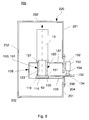
- Fig. 7 shows schematically a cross section of a sputtering installation according to embodiments
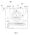
- Fig. 8 shows schematically a cross section of a sputtering installation according to embodiments
- Sputtering is a process in which atoms are ejected from a solid target material due to bombardment of the target by energetic particles.
- the process of coating a substrate as a material at the scraping refers typically to thin film applications.
- coating and the term “depositing” are used synonymously herein.
- sputtering installation and “deposition apparatus” are used synonymously herein and shell embrace an apparatus which uses sputtering for depositing a target material, typically as a thin film, on a substrate.
- Typical target materials include but are not limited to pure metals such as aluminum (A1), copper (Cu), silver (Ag) and gold (Au), metal alloys such as such as an aluminum-niobium (AlNb) alloy or an aluminum-nickel (AlNi) alloy, semiconductor materials such as silicon (Si) and dielectric materials such as nitrides, carbides, titanates, silicates, aluminates and oxides, in particular nitrides, carbides, titanates, silicates, aluminates or oxides of the above-mentioned materials.
- transparent conducting oxides such as impurity-doped ZnO, e.g. ZnO:Al, AlZnO, In 2 O 3 , SnO 2 and CdO, as well as Sn doped In 2 O 3 (ITO) and F doped SnO 2 .
- TCO transparent conducting oxides
- substrate as used herein shall embrace both inflexible substrates, e.g. a wafer or a glass plate, and flexible substrates such as webs and foils.
- Representative examples include but are not limited to applications involving: semiconductor and dielectric materials and devices, silicon-based wafers, flat panel displays (such as TFTs), masks and filters, energy conversion and storage (such as photovoltaic cells, fuel cells, and batteries), solid-state lighting (such as LEDs and OLEDs), magnetic and optical storage, micro-electro-mechanical systems (MEMS) and nano-electro-mechanical systems (NEMS), micro-optic and opto-elecro-mechanical systems (NEMS), micro-optic and optoelectronic devices, transparent substrates, architectural and automotive glasses, metallization systems for metal and polymer foils and packaging, and micro- and nano-molding.
- MEMS micro-electro-mechanical systems
- NEMS nano-electro-mechanical systems
- NEMS micro-optic and opto-elecro-mechanical systems
- micro-optic and optoelectronic devices transparent substrates, architectural and automotive glasses, metallization systems for metal and polymer foils and packaging, and micro- and
- end-block shall embrace a device which is adapted to be mounted to a non-revolving part, typically to a wall, flap or door, of a sputtering installation and which is adapted to transfer rotary movement to a rotatable target.
- end-block and the term “cathode drive-block” are used synonymously herein.
- end-block and “cathode drive-block” as used herein shall particularly embrace devices which in addition provide coolant and/or electrical current to the rotatable target while maintaining vacuum integrity and a closed coolant circuit.
- the bearing of the end-block is typically desired to reliably bear heavy mechanical loads over a long period of time.
- rotatable target shall embrace any cathode assembly which is adapted to be rotatably mounted to a sputtering installation and which includes a target structure adapted for being sputtered.
- rotatable target shall particularly embrace magnetically enhanced cathode assemblies which in addition include internal magnetic means, e.g. permanent magnets, for improved sputtering.
- Rotatable targets in the following also referred to as rotatable sputtering cathodes and rotary cathodes, respectively, may be made of a hollow cylindrical body of the target material. These rotary targets are also referred to as monolithic targets and may be manufactured by casting or sintering of the target material.
- Non-monolithic rotatable targets typically include a cylindrical rotatable tube, e.g. a backing tube, having a layer of the target material applied to the outer surface thereof.
- the target material may for example be applied by spraying onto, or casting or isostatic pressing of powder onto the outer surface of a backing tube.
- a hollow cylinder of a target material which may also be referred to as a target tube, may be arranged on and bonded, e.g. with indium, to the backing tube for forming a rotary cathode.
- non-bonded target cylinders can be provided radially outward of a backing tube.
- Magnetic means which may include an array of magnets, may be arranged inside the sputtering cathode, e.g. inside a backing tube or inside a monolithic target, and provide a magnetic field for magnetically enhanced sputtering.
- the cathode is typically rotatable about its longitudinal axis so that it can be turned relative to the magnetic means.
- un-cooled magnets may become hot. This is due to the fact that they are surrounded by target material that is bombarded with ions. The resulting collisions lead to a heating up of the rotary cathode.
- a cooling of the target material and the magnets may be provided.
- Fig. 1A shows schematically an end-block 100 in a typical cross section along a rotational axis 50 around which a rotatable target (not shown) may rotate during sputtering.
- the rotational axis 50 also forms a longitudinal axis 50 of the end-block 100 and defines an axial direction.
- directional terminology such as “top,” “bottom,” “upper,” “lower,” “above,” “below,” “on,” etc., is used with reference to the orientation of the rotational axis 50.
- the term “axial load” as used herein intends to describe a load and force, respectively, in direction to the rotational axis 50.
- radial load intends to describe a load and force, respectively, in a direction which is essentially orthogonal to the rotational axis 50.
- radial direction intends to describe a direction which is essentially orthogonal to the rotational axis 50.
- the end-block 100 includes a base body 110, a rotary bearing 140 which is arranged around the base body 110, and a bearing housing 123 which is arranged around and connected to the rotary bearing 140.
- the bearing housing 123 forms a part of a rotor carrying the rotatable target for sputtering.
- the base body 110 is rigidly connected to a non-revolving part of a deposition apparatus (not shown), typically to an external housing of the end-block 100 which is mounted to e.g. a wall of the deposition apparatus.
- Arranging a rotor, which is adapted to mechanically support the rotational target, around a non-rotating base body 110 results in a compact and space reduced design of the end-block 100.
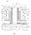
- FIG. 1 shows schematically the end-block 100 in a typical cross section along a rotational axis 50 around which a rotatable target (not shown) may rotate during sputtering.
- the end-block 100 includes an external housing.
- the external housing does typically not rotate relative to the process chamber in which the sputtering is carried out.
- the process chamber is typically a low pressure chamber and in the following also referred to as vacuum chamber.
- the external housing may e.g. be attached to a wall of the process chamber.
- the external housing is typically made of a metal, e.g. steel, stainless steel or aluminum.
- the end-block 100 has a base body 110, typically a hollow base body 110, which is rigidly connected to the lower wall 126 of the external housing. Therefore, the base body 110 does also not rotate relative to the process chamber during sputtering.
- the base body 110 is typically rigidly connected to a non-revolving part of the deposition apparatus.
- a fluid support for the rotational target is provided within the base body 110 .
- a cylindrical cavity 113 which is coaxial to the rotational axis 50, is formed in the base body 110.
- a coolant tube 114 is coaxially inserted into the cylindrical cavity 113.
- a hollow cylindrical interspace 115 is typically formed between the coolant tube 114 and the inner walls of the base body 110.
- the coolant tube 114 and the interspace 115 may be used to support the rotational target with coolant, e.g. water.
- coolant e.g. water.
- cold coolant flows upwards in the interspace 115 and warmed up coolant flows downwards in the coolant tube 114.
- the flow direction of the coolant may also be reversed.
- a bearing system 149 is arranged around the base body 110.
- the bearing system 149 is typically coaxial to the rotational axis, i.e. the bearing system 149 determines the rotational axis 50.
- a rotor 120 is arranged around the bearing system 149.
- the rotor 120 is in an upper part outside the external housing adapted to receive the rotational target. Thereby, the rotational target may be rotated around the rotational axis.
- the rotor 120 provides mechanical support for the rotational target, i.e. the rotor 120 typically carries the rotational target and transfers rotational movement to the rotational target during sputtering.
- Arranging a rotor 120, which is adapted to mechanically support the rotational target, around a non-rotating base body 110 results in a compact and space reduced design of the end-block 100. Thereby, space within the process chamber and hence costs can be reduced.
- the bearing system 149 is adapted to carry both radial and axial loads resulting from the movement of the rotatable target during sputtering.
- the bearing system 149 includes at least one tapered roller bearing, e.g. one annular tapered roller bearing. Tapered roller bearings support both radial and axial loads, and typically can carry higher loads than e.g. ball bearings due to greater contact area.
- the rotor 120 includes a bearing housing 123 which is arranged around and connected to the bearing system 149.
- Typical cross-sections which are orthogonal to the rotational axis 50 and go through the bearing system 149 may show annular sections of the bearing housing 123, the coolant tube 114 and the base body 110.
- a gear-wheel 151 is arranged around and fastened to the bearing housing 123 to transfer rotational movement to the rotor 120.
- the gear-wheel 151 is fastened to a lower part, as shown in Fig. 1 , or a middle part of the bearing housing 123. This facilitates mechanical coupling between the gear-wheel 151 and a rotating electric drive through the external housing, e.g. via a belt.
- a target flange 121 is arranged on and vacuum tightly mounted to the bearing housing 123.
- an O-ring seal 13 is arranged between the bearing housing 123 and the target flange 121.
- a rotatable target mounted on top of the target flange 121 may be rotated by the rotating electric drive.
- a seal carrier 124 is, according to embodiments, vacuum-tightly arranged between the upper wall 127 of the external housing and the rotor 120.
- a sliding annular vacuum seal 118 is arranged between the seal carrier 124 and the bearing housing 123.
- the seal carrier 124 may also be attached to the bearing housing 123 and a sliding annular vacuum seal may be arranged between the seal carrier 124 and the upper wall 127 of the external housing.
- two annular sliding seals 117 are arranged between the target flange 121 and the base body 110.
- Using at least one annular sliding fluid seal avoids an exchange of coolant, bearing grease and vacuum lubricants, respectively. Thereby, the bearing system 149 is protected against penetration of coolant. Further, penetration of grease into the cooling system is avoided.
- a current collector plate 122 is mounted to the bearing housing 123 at a lower end of the rotor 120, i.e. opposite to the target flange 121.
- the current collector plate 122 is typically also of an annular shape in cross-sections which are orthogonal to the rotational axis 50.
- the current collector plate 122 is typically used to transmit electric current to the rotatable target.
- a combined coolant unit and electrical support unit 130 is arranged below the current collector plate 122.
- the combined unit 130 is non-rotatable to the base body 110 and includes both a discharge tube 131 and at least one coolant supply tube 132 (see Fig .3 ) which lead through the base body 110.
- sliding electrical contacts 135 are arranged on and protrude of, respectively, a main body 133 of the combined unit 130 and in contact with the current collector plate 122. Thereby, the rotational target may be provided with electrical and fluid support.
- an insulating plate 116 which is orientated perpendicular to the rotational axis 50 is fastened, typically with screws 204, to a lower part 119 of the base body 110.
- the inner part of the end-block 100 i.e. the base body 110, is insulated against and non-rotatably mounted to the external housing.
- the insulating plate 116 is fastened, typically screwed, to the lower wall 126 to stabilize the base body 110 in the external housing and to fix the rotational axis 50 relative to the external housing.
- the insulating plate 116 and the lower wall 126 may be screwed together using additional screws.
- the shown screws 204 may extend at least partially into the lower wall 126. In this event, the screws 204 are typically insulated against the lower part 119 of the base body 110.
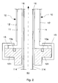
- Fig. 2 shows schematically a cross section of a rotatable target 10 mounted to a target flange 121 of an end-block along the rotational axis 50.
- the target flange 121 and the rotatable target 10 are coaxial to each other.
- rotatable target shall embrace any cathode assembly which is adapted to be rotatably mounted to a sputtering installation and which includes a target structure adapted for being sputtered.
- rotatable target shall particularly embrace magnetically enhanced cathode assemblies which in addition include internal magnetic means, e.g. permanent magnets, for improved sputtering.
- the rotatable target 10 includes a backing tube 11 and a target tube 12 disposed on the backing tube 11.
- target tube shall embrace any shell, in particular formed as a hollow cylinder, of material suitable to be sputtered.
- Support of the target tube may include mechanical support, providing electrical contact and providing cooling of the target tube and the optional magnets.
- the rotatable target may also be a monolithic target.
- the shape of the rotatable target may be similar to the shape of the rotatable target 10 shown in Fig. 2 .
- the shown adjoining regions 11 and 12 typically form, in this case, a simply-connected region of the same material.
- Support of the rotatable target may include at least one of mechanical support, providing electrical contact and providing cooling of the target tube and the optional magnets.
- the rotatable target 10 is fitted to an upper part of the target flange 121 using an annular clamp 15 which presses the rotatable target 10 to the target flange 121.
- An O-ring seal 13a is typically arranged between the target flange 121 and an adjoining part of the backing tube 11 and the rotatable target 10, respectively. Accordingly, the rotatable target 10 is vacuum-tightly mounted to the target flange 121.
- the rotatable target 10 is vacuum-tightly mounted to the upper part of the target flange 121. This is typically achieved by an annular sealing (not shown). Thereby, fluid leakage to the low pressure process chamber is prevented.
- the rotatable target 10 includes a tubular internal structure 16 that is liquid-tightly mounted to a coolant tube 114 of the end-block for cooling the rotatable target 10, in particular optional magnets (not shown) provided inside the rotatable target 10.
- At least one electric supply (not shown) for the rotatable target 10 is typically also provided through the target flange 121.
- the target flange is adapted to mechanically support the rotatable target.
- coolant and electric supply for the target tube may be provided through the target flange.
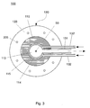
- Fig. 3 shows schematically a cross section of the end-block 100 along the line A-A' of Fig. 1 .
- the end-block 100 includes a coolant supply and discharge unit 130 which is arranged between the current collector plate and the insulating plate.
- the cross section of Fig. 3 corresponds to a section through the coolant supply and discharge unit 130.
- the coolant supply and discharge unit 130 includes a discharge tube 131 and two coolant supply tubes 132 which are fed through the base body 110 and a main body 133 of the unit 130 in a plane essentially perpendicular to the axis 50.
- the discharge tube 131 leads into an opening of the coolant tube 114 and the coolant supply tubes 132 lead into the annular coolant interspace 115 formed between the base body 110 and coolant tube 114.
- a coolant may be provided to the supply tubes 132.
- the coolant typically flows through the supply tubes 132 and upwards in the coolant interspace 115 to the rotatable target.
- the backflow of the warmed-up coolant typically goes downwards through the coolant tube 114 and is discharged in radial direction through the discharge tube 131, as indicated by the dashed arrow.
- a closed coolant circuit may be provided for the rotatable target.
- the flow direction in the closed coolant circuit may also be reversed.
- the coolant supply and discharge unit 130 includes in a radially outward part through holes for fastening, typically screwing, the coolant supply and discharge unit 130 to the lower part 119 of the base body 110.
- sliding electric contacts are provided on top of the coolant supply and discharge unit 130 .
- the sliding electric contacts are arranged above the cross section of Fig. 3 and are therefore not shown.
- the support structure for the sliding contacts are also not shown.
- the sliding electric contacts and their support structure typically form an electrical support unit.
- the end-block includes a coolant supply and discharge unit and/ or an electrical support unit which are arranged between the current collector plate and the insulating plate.
- the end-block may e.g. include a combined unit integrating the functions of the electrical support unit and the coolant supply and discharge unit.
- Fig. 4 shows schematically a cross section of an end-block along the rotational axis 50 according to embodiments.
- the end-block 101 of Fig. 4 is similar to the end-block 100 of Fig. 1 .
- Most of the elements in Fig. 4 are similar to the corresponding elements in Fig. 1 . For sake of clarity, these elements are referred to with the same respective reference numbers.
- the end-block 101 includes a base body 110 which is adapted to be rigidly coupled to a non-revolving part of a sputtering installation.
- the end-block 101 further includes a rotor 120 which is rotatably mounted around the base body 110 and adapted to receive the rotatable target. Accordingly, the rotatable target may be fastened to a target flange 121 of the end-block 101 as explained with reference to Fig. 2 for the target flange of the end-block of Fig. 1 .
- Fig. 3 may also correspond to a cross section along the line AA' in Fig. 4 .
- the end-block 101 includes two annular rotary bearings 140 and 141 which are arranged between the base body 110 and the rotor 120 and spaced apart from each other in axial direction.
- two rotary bearings 140 and 141 allows for a particularly compact and comparatively lightweight design of the bearing system.
- at least one of the two rotary bearings 140 and 141 is adapted to carry both radial and axial loads.
- annular slotted round nut 142 is arranged between the base body 110 and the rotor 120.
- the annular slotted round nut 142 typically presses the rotary bearing 141 and, therefore, braces the rotor 120 relative to the base body 110. This allows for a stable bearing of the typically long rotatable target.
- the screws 204 are insulated against the lower part 119 of the base body 110 by respective insulating washers 206. Accordingly, the screws 204 may extend into the lower wall 126 without electrically connecting the lower wall 126 of the external housing with the base body 110.
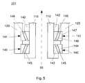
- Fig. 5 shows schematically a section of the cross section of Fig. 4 according to embodiments.
- Each of the two rotary bearings 140 and 141 include an inner ring 143 and 146, respectively, an outer ring 144 and 147, respectively, and a conical roller 145 and 148, respectively, running on the conical races.
- the rotary bearings 140 and 141 are, according to embodiments, annular tapered roller bearing. Due to their design, the tapered roller bearings 140 and 141 support both radial and axial loads.
- the inclination of the conical roller 145 and 148 is opposite relative to the rotational axis 50 but typically of same absolute value.
- the bearing system can equally well carry both positive and negative axial loads.
- the inner rings 143 and 146 are fastened to the base body 110 and the outer ring 144 and 147 are fastened to the bearing housing 132.
- the bearings 140 and 141 are arranged around the base body 110 and the rotor 120 is arranged around the bearings 140 and 141.
- an annular slotted round nut 142 presses the rotary bearing 141.
- the rotary bearing 141 is pre-stressed.
- this also results in pre-stressing of the rotary bearing 140 via the bearing housing 132. This allows for a stable bearing of a typically long rotatable target.
- Fig. 6 shows schematically a cross section of a sputtering installation 200 along the rotational axis 50 according to embodiments.
- the sputtering installation 200 typically includes a process chamber 220 formed by walls 231 and 232.
- the axis 50 of the cathode, the target, the backing tube or the bearing is essentially parallel to the wall 231 the end-block 100, 101is attached to.
- a drop-in configuration of the cathode is realized.
- At least one end-block 100 or 101 is mounted into the process chamber 220 such that the base body 110 of the end-block 100, 101 is not rotatably relative to the walls 231 of the process chamber 220.
- the base body 110 is typically fastened via an insulating plate 116 and to a flap or door 230 of the process chamber 220. During sputtering, the flap or door 230 is closed. Accordingly, the base body 110 is typically stationary, at least non-rotatable, during sputtering.
- the external housing 125 may be fastened directly to a wall 231 of the process chamber 220.
- a rotating drive 150 typically an electrical drive is arranged outside the process chamber 220 via a mounting support 152.
- the rotating drive 150 may, however also be placed within the external housing 125.
- the rotating drive 150 drives the rotatable target 10 during sputtering via its motor axis 154, a pinion 153 connected thereto and a chain or a toothed belt (not shown) which loops around the pinion 153 and a gear-wheel 151 attached to a bearing housing 123 of the rotor 120.
- coolant support tubes 134 and/or electrical support lines 134 are fed from the coolant supply and discharge unit 130 and/or an electrical support unit 130 through the external housing 125 to the outside of the process chamber 220.
- the rotatable target 10 is typically supported by the end-block 100, 101 in a cantilevered arrangement above a substrate (not shown). In addition, the rotatable target 10 may be further supported at its upper end.
- Fig. 7 shows schematically a cross section of a sputtering installation 200 according to embodiments.
- the axis 50 of the cathode, the target, the backing tube or the bearing is essentially perpendicular to the flange 230 connecting the end-block 100, 101 to the processing chamber 220.
- the sputtering installation 200 of Fig. 7 is similar to the sputtering installation of Fig. 6 .
- the insulating plate 116 in Fig. 7 is orientated parallel to the wall 231 and flap 230, respectively, to which the end-block 100, 101 is mounted. Different thereto, the insulating plate 116 in Fig.
- the lower wall 126 of the external housing 125 is mounted to the wall 231 or to the door 230 and flap 230, respectively, as shown in Fig. 7 .
- the end-block 100, 101 is mounted to the wall 231 such that the wall 231 of the vacuum chamber 220 and the upper wall 127 of the external housing 125 form an essentially flat transition region inside the vacuum chamber 220 or a transition region having a small step only. This is indicated by the dotted horizontal lines in Fig. 7 .
- the internal volume of the vacuum chamber 220 may be reduced.
- the arrangement of Fig. 7 is typically used for sputtering installations in which the substrate is orientated horizontally with respect to gravity.
- the arrangement of Fig. 6 may be used for horizontally and vertically orientated substrates.
- Fig. 8 illustrates a sputtering installation 200 as shown in Fig. 6 and 7 .
- the schematic cross-section of Fig. 8 is orthogonal to the cross-section of Fig. 6 and 7 , respectively.
- the sputtering installation 200 has a vacuum chamber 220 including a gas inlet 201 for providing processing gas, for example argon, to the vacuum chamber 220.
- the vacuum chamber 220 further includes a substrate support 202 and a substrate 203 arranged on the substrate support 202.
- the vacuum chamber 220 includes a rotatable target 10, typically in a cantilevered arrangement above the substrate 203.
- a high voltage difference is applied between the rotatable target 10 operating as a cathode and the substrate support 202 operating as an anode.
- the plasma is typically formed by impact ionization of accelerated electrons with e.g. Argon atoms.
- the formed Argon ions are accelerated in direction of rotatable target 10 such that particles, typically atoms, of the rotatable target 10 are sputtered and subsequently deposited on the substrate 203.
- the pressure in the plasma area can be about 10 -4 mbar to about 10 -2 mbar, typically about 10 -3 mbar.
- the vacuum chamber 220 may include one or more openings and/or valves for introducing or retracting the substrate 203 in or out of the vacuum chamber 220.
- Magnetron sputtering is particularly advantageous in that its deposition rates are rather high.
- free electrons within the generated magnetic field directly below the target surface may be trapped. This enhances the probability of ionizing the gas molecules typically by several orders of magnitude. In turn, the deposition rate may be increased significantly.
- stationary or time varying magnetic fields may be used.
- a cooling fluid is typically circulating within rotatable target 10 for cooling the magnets 224 and/ or the target 10.
- the rotatable target 100 is typically supported by a cathode drive-block 100, 101 which is not visible in the shown cross-section and therefore drawn as a dashed circle.
- the cathode drive-block 100, 101 is non-rotatably mounted to a wall 230 or door 231 or flap 231 of the process chamber 220 which is not visible in the shown cross-section and therefore drawn as a rectangle.
- the cathode drive-block typically includes a base body which is adapted to be rigidly coupled to a non-revolving part such as a wall, door or flap of the sputtering installation.
- the sputtering installation includes a process chamber having a wall to which the cathode drive-block is attached such that the rotational axis of the cathode, the target, the backing tube or the bearing is parallel to the wall, i.e. with an angular accuracy of at least 5°.
- a rotor which is adapted to receive the rotatable target, is rotatably mounted around the base body.
- a bearing system is arranged between the base body and the rotor.
- the bearing system is typically adapted to carry radial and axial loads.
- the bearing system includes at least one rotary bearing.
- the bearing system includes two annular tapered roller bearings which are spaced apart from each other in direction of the rotational axis and arranged between the base body and the rotor.
- the bearing system further includes an annular slotted round nut arranged between the base body and the rotor.
- the annular slotted round nut typically braces the two annular tapered roller bearings against one another.
- the rotor includes at an upper end a target flange which is adapted to mechanically support the rotatable target.
- the rotor further includes a bearing housing which is vacuum-tightly attached to the target flange.
- the cathode drive-block includes a rotating drive which is mechanically connected to the bearing housing.
- two or more rotatable targets may be supported by respective cathode drive-blocks and disposed in the vacuum chamber.
- the cylindrical axes of the two or more rotatable targets are substantially parallel, i.e. parallel within an angular accuracy of at least 5°, more typically within an angular accuracy of at least 1°.
Description
- The present disclosure relates to an end-block for carrying a rotatable target, particularly to an end-block including a bearing. Further, the present disclosure relates to a sputtering installation including an end-block.
- In many applications it is desired to deposit thin layers on a substrate. Known techniques for depositing thin layers are in particular evaporating, chemical vapor sputtering and sputtering deposition. For example, sputtering can be used to deposit a thin layer such as a thin layer of a metal, e.g. aluminum, or ceramics. During the sputtering process, the coating material is transported from a sputtering target consisting of that material to the substrate to be coated by bombarding the surface of the target with ions of a typically inert processing gas at low pressure. The ions are produced by electron impact ionization of the processing gas and accelerated by a high voltage drop between the target operating as a sputtering cathode and an anode. This bombardment of the target results in the ejection of atoms or molecules of the coating material, which accumulate as a deposited film on the substrate arranged opposite to the sputtering cathode, e.g. below the sputtering cathode.
- Segmented planar, monolithic planar and rotatable targets may be used for sputtering. Due to the geometry and design of the cathodes, rotatable targets typically have a higher utilization and an increased operation time than planar ones. Accordingly, the use of rotatable targets typically prolongs service lives and reduces costs.
- The rotary cathode is typically supported by a cathode drive unit of the sputtering installation. In the following the cathode drive unit is also referred to as an end-block and a cathode drive-block, respectively. During sputtering, the cathode drive unit rotatably transfers movement to the rotary cathode. Given longitudinal extensions of rotary cathodes of up to about 4 m and typical continuous operation times of sputtering installations of several days, the bearing of the cathode drive unit is typically desired to reliably bear heavy mechanical loads over a long period of time.
- Typical functionalities of end-blocks are outlined in document
US 2008/0128276 A1 . Further, documentUS 2006/0157346 A1 describes rotatable target assemblies, in particular for small sized installations, with a gas-to-vacuum seal and a gas-to-coolant seal inside the target tube. The bearing system for rotatably supporting the target tube may be arranged inside or outside the target tube. - Sputtering is typically carried out under low pressure or vacuum condition, i.e. in a vacuum chamber. For cost reasons, cathode drive units, in particular when arranged within a vacuum chamber of a sputtering installation, are typically also desired to have low space requirements. Realizing a reliable and less space bearing of the rotatable target is, however, a demanding task. Accordingly, there is an ongoing need for improved cathode drive units, in particular compact cathode drive units.
- Embodiments of the invention provide an end-block for a rotatable target and a deposition apparatus as set forth in
independent claims 1 and 14, respectively. - So that the manner in which the above recited features of the present invention can be understood in detail, a more particular description of the invention, briefly summarized above, may be had by reference to embodiments. The accompanying drawings relate to embodiments of the invention and are described in the following:
- According to an embodiment, an end-block for carrying a rotatable target of a deposition apparatus is provided. The end-block includes a base body which is adapted to be rigidly connected to a non-revolving part of the deposition apparatus. The end-block further includes at least one rotary bearing which is arranged around the base body and defines a rotational axis, and a rotor which is arranged around the base-body and adapted to receive the rotatable target.
- According to an embodiment, a deposition apparatus, which has a process chamber with a non-revolving part and at least one end-block mounted thereto, is provided. The end-block includes a base body, at least one rotary bearing arranged around the base body and a rotor arranged around the at least one rotary bearing. The base body is fixed to a non-revolving part of the deposition apparatus and the rotor is adapted to receive a rotatable target.
- According to an embodiment, a cathode drive-block of a sputtering installation for supporting a rotatable target is provided. The drive-block includes a base body which is adapted to be rigidly coupled to a non-revolving part of the sputtering installation. Further, the drive-block includes a rotor which is rotatably mounted around the base body and adapted to receive the rotatable target.
- Further aspects, advantages and features of the present invention are apparent from the dependent claims, the description and the accompanying drawings.
- Some of the above mentioned embodiments will be described in more detail in the following description of typical embodiments with reference to the following drawings in which:
-
Fig. 1A shows schematically a cross section of an end-block along a rotational axis according to embodiments; -
Fig. 1 shows schematically a cross section of an end-block along a rotational axis according to embodiments; -
Fig. 2 shows schematically a cross section of a rotatable target mounted to a target flange of an end-block along a rotational axis according to embodiments; -
Fig. 3 shows schematically a cross section of an end-block along the line A-A' ofFig. 1 according to embodiments; -
Fig. 4 shows schematically a cross section of an end-block along a rotational axis according to embodiments; -
Fig. 5 shows schematically a section of the cross section ofFig. 4 according to embodiments; -
Fig. 6 shows schematically a cross section of a sputtering installation according to embodiments; -
Fig. 7 shows schematically a cross section of a sputtering installation according to embodiments; -
Fig. 8 shows schematically a cross section of a sputtering installation according to embodiments; - The elements of the drawing are not necessarily to scale relative to each other. Like reference numerals designate corresponding similar parts.
- Reference will now be made in detail to the various embodiments, one or more examples of which are illustrated in each figure. Each example is provided by way of explanation and is not meant as a limitation. For example, features illustrated or described as part of one embodiment can be used on or in conjunction with other embodiments to yield yet further embodiments. It is intended that the present disclosure includes such modifications and variations.
- Sputtering is a process in which atoms are ejected from a solid target material due to bombardment of the target by energetic particles. The process of coating a substrate as a material at the scraping refers typically to thin film applications. The term "coating" and the term "depositing" are used synonymously herein. The terms "sputtering installation" and "deposition apparatus" are used synonymously herein and shell embrace an apparatus which uses sputtering for depositing a target material, typically as a thin film, on a substrate.
- Typical target materials include but are not limited to pure metals such as aluminum (A1), copper (Cu), silver (Ag) and gold (Au), metal alloys such as such as an aluminum-niobium (AlNb) alloy or an aluminum-nickel (AlNi) alloy, semiconductor materials such as silicon (Si) and dielectric materials such as nitrides, carbides, titanates, silicates, aluminates and oxides, in particular nitrides, carbides, titanates, silicates, aluminates or oxides of the above-mentioned materials. For example, transparent conducting oxides (TCO) such as impurity-doped ZnO, e.g. ZnO:Al, AlZnO, In2O3, SnO2 and CdO, as well as Sn doped In2O3 (ITO) and F doped SnO2.
- The term "substrate" as used herein shall embrace both inflexible substrates, e.g. a wafer or a glass plate, and flexible substrates such as webs and foils.
- Representative examples include but are not limited to applications involving: semiconductor and dielectric materials and devices, silicon-based wafers, flat panel displays (such as TFTs), masks and filters, energy conversion and storage (such as photovoltaic cells, fuel cells, and batteries), solid-state lighting (such as LEDs and OLEDs), magnetic and optical storage, micro-electro-mechanical systems (MEMS) and nano-electro-mechanical systems (NEMS), micro-optic and opto-elecro-mechanical systems (NEMS), micro-optic and optoelectronic devices, transparent substrates, architectural and automotive glasses, metallization systems for metal and polymer foils and packaging, and micro- and nano-molding.
- With respect to
Fig. 1A , embodiments pertaining to end-blocks are explained. The term "end-block" as used herein shall embrace a device which is adapted to be mounted to a non-revolving part, typically to a wall, flap or door, of a sputtering installation and which is adapted to transfer rotary movement to a rotatable target. The terms "end-block", "cathode drive-head" and the term "cathode drive-block" are used synonymously herein. The terms "end-block", "cathode drive-head" and "cathode drive-block" as used herein shall particularly embrace devices which in addition provide coolant and/or electrical current to the rotatable target while maintaining vacuum integrity and a closed coolant circuit. - Given longitudinal extensions of rotatable targets of up to about 1.5 m, up to about 2.5 m or even up to about 4 m and typical continuous operation times of sputtering installations of several days, the bearing of the end-block is typically desired to reliably bear heavy mechanical loads over a long period of time.
- The term "rotatable target" as used herein shall embrace any cathode assembly which is adapted to be rotatably mounted to a sputtering installation and which includes a target structure adapted for being sputtered. The term "rotatable target" as used herein shall particularly embrace magnetically enhanced cathode assemblies which in addition include internal magnetic means, e.g. permanent magnets, for improved sputtering.
- Rotatable targets, in the following also referred to as rotatable sputtering cathodes and rotary cathodes, respectively, may be made of a hollow cylindrical body of the target material. These rotary targets are also referred to as monolithic targets and may be manufactured by casting or sintering of the target material.
- Non-monolithic rotatable targets typically include a cylindrical rotatable tube, e.g. a backing tube, having a layer of the target material applied to the outer surface thereof. In the manufacture of such rotatable sputtering cathodes, the target material may for example be applied by spraying onto, or casting or isostatic pressing of powder onto the outer surface of a backing tube. Alternatively, a hollow cylinder of a target material, which may also be referred to as a target tube, may be arranged on and bonded, e.g. with indium, to the backing tube for forming a rotary cathode. According to yet further alternatives, non-bonded target cylinders can be provided radially outward of a backing tube.
- In order to obtain increased deposition rates, the use of magnetically enhanced cathodes has been proposed. This may also be referred to as magnetron sputtering. Magnetic means, which may include an array of magnets, may be arranged inside the sputtering cathode, e.g. inside a backing tube or inside a monolithic target, and provide a magnetic field for magnetically enhanced sputtering. The cathode is typically rotatable about its longitudinal axis so that it can be turned relative to the magnetic means.
- In operation, un-cooled magnets may become hot. This is due to the fact that they are surrounded by target material that is bombarded with ions. The resulting collisions lead to a heating up of the rotary cathode. In order to keep the magnets at a suitable operating temperature, a cooling of the target material and the magnets may be provided.
-
Fig. 1A shows schematically an end-block 100 in a typical cross section along arotational axis 50 around which a rotatable target (not shown) may rotate during sputtering. Therotational axis 50 also forms alongitudinal axis 50 of the end-block 100 and defines an axial direction. In this regard, directional terminology, such as "top," "bottom," "upper," "lower," "above," "below," "on," etc., is used with reference to the orientation of therotational axis 50. The term "axial load" as used herein intends to describe a load and force, respectively, in direction to therotational axis 50. Accordingly, the term "radial load" as used herein intends to describe a load and force, respectively, in a direction which is essentially orthogonal to therotational axis 50. Likewise, the term "radial direction" as used herein intends to describe a direction which is essentially orthogonal to therotational axis 50. - According to an embodiment, which may be combined with other embodiments disclosed herein, the end-
block 100 includes abase body 110, arotary bearing 140 which is arranged around thebase body 110, and a bearinghousing 123 which is arranged around and connected to therotary bearing 140. The bearinghousing 123 forms a part of a rotor carrying the rotatable target for sputtering. During sputtering, thebase body 110 is rigidly connected to a non-revolving part of a deposition apparatus (not shown), typically to an external housing of the end-block 100 which is mounted to e.g. a wall of the deposition apparatus. - Arranging a rotor, which is adapted to mechanically support the rotational target, around a
non-rotating base body 110 results in a compact and space reduced design of the end-block 100. - With respect to
Fig. 1 several embodiments of an end-block 100 are explained.Fig. 1 shows schematically the end-block 100 in a typical cross section along arotational axis 50 around which a rotatable target (not shown) may rotate during sputtering. - Typically, the end-
block 100 includes an external housing. In the shown cross-section, only parts of alower wall 126 and anupper wall 127 of the external housing are shown. During sputtering, the external housing does typically not rotate relative to the process chamber in which the sputtering is carried out. The process chamber is typically a low pressure chamber and in the following also referred to as vacuum chamber. The external housing may e.g. be attached to a wall of the process chamber. For stability reasons, the external housing is typically made of a metal, e.g. steel, stainless steel or aluminum. - According to embodiments, the end-
block 100 has abase body 110, typically ahollow base body 110, which is rigidly connected to thelower wall 126 of the external housing. Therefore, thebase body 110 does also not rotate relative to the process chamber during sputtering. - In other words, the
base body 110 is typically rigidly connected to a non-revolving part of the deposition apparatus. - Typically, within the base body 110 a fluid support for the rotational target is provided. According to embodiments, a
cylindrical cavity 113, which is coaxial to therotational axis 50, is formed in thebase body 110. Typically, acoolant tube 114 is coaxially inserted into thecylindrical cavity 113. In addition, a hollowcylindrical interspace 115 is typically formed between thecoolant tube 114 and the inner walls of thebase body 110. Thecoolant tube 114 and theinterspace 115 may be used to support the rotational target with coolant, e.g. water. Typically, cold coolant flows upwards in theinterspace 115 and warmed up coolant flows downwards in thecoolant tube 114. The flow direction of the coolant may also be reversed. - According to embodiments, a
bearing system 149 is arranged around thebase body 110. Thebearing system 149 is typically coaxial to the rotational axis, i.e. thebearing system 149 determines therotational axis 50. According to embodiments, arotor 120 is arranged around thebearing system 149. Therotor 120 is in an upper part outside the external housing adapted to receive the rotational target. Thereby, the rotational target may be rotated around the rotational axis. Typically, therotor 120 provides mechanical support for the rotational target, i.e. therotor 120 typically carries the rotational target and transfers rotational movement to the rotational target during sputtering. Arranging arotor 120, which is adapted to mechanically support the rotational target, around anon-rotating base body 110 results in a compact and space reduced design of the end-block 100. Thereby, space within the process chamber and hence costs can be reduced. - According to embodiments, the
bearing system 149 is adapted to carry both radial and axial loads resulting from the movement of the rotatable target during sputtering. Typically, thebearing system 149 includes at least one tapered roller bearing, e.g. one annular tapered roller bearing. Tapered roller bearings support both radial and axial loads, and typically can carry higher loads than e.g. ball bearings due to greater contact area. - According to embodiments, the
rotor 120 includes a bearinghousing 123 which is arranged around and connected to thebearing system 149. Typical cross-sections which are orthogonal to therotational axis 50 and go through thebearing system 149 may show annular sections of the bearinghousing 123, thecoolant tube 114 and thebase body 110. - According to embodiments, a gear-
wheel 151 is arranged around and fastened to the bearinghousing 123 to transfer rotational movement to therotor 120. Typically, the gear-wheel 151 is fastened to a lower part, as shown inFig. 1 , or a middle part of the bearinghousing 123. This facilitates mechanical coupling between the gear-wheel 151 and a rotating electric drive through the external housing, e.g. via a belt. - According to embodiments, a
target flange 121 is arranged on and vacuum tightly mounted to the bearinghousing 123. Typically, an O-ring seal 13 is arranged between the bearinghousing 123 and thetarget flange 121. As thetarget flange 121 and the bearinghousing 123 are typically non-rotatably coupled to each other, a rotatable target mounted on top of thetarget flange 121 may be rotated by the rotating electric drive. - During sputtering, at least an upper part or the
target flange 121 is typically arranged outside the external housing, i.e. in a low pressure or vacuum environment. Different thereto, the internal space of the external housing is typically at normal and/or a higher pressure than the process chamber. To avoid an exchange of gas, aseal carrier 124 is, according to embodiments, vacuum-tightly arranged between theupper wall 127 of the external housing and therotor 120. In a typical embodiment a slidingannular vacuum seal 118 is arranged between theseal carrier 124 and the bearinghousing 123. Theseal carrier 124 may also be attached to the bearinghousing 123 and a sliding annular vacuum seal may be arranged between theseal carrier 124 and theupper wall 127 of the external housing. - According to embodiments, two annular sliding
seals 117, e.g. fluid seals 117, are arranged between thetarget flange 121 and thebase body 110. Using at least one annular sliding fluid seal avoids an exchange of coolant, bearing grease and vacuum lubricants, respectively. Thereby, thebearing system 149 is protected against penetration of coolant. Further, penetration of grease into the cooling system is avoided. - According to embodiments, a
current collector plate 122 is mounted to the bearinghousing 123 at a lower end of therotor 120, i.e. opposite to thetarget flange 121. Thecurrent collector plate 122 is typically also of an annular shape in cross-sections which are orthogonal to therotational axis 50. Thecurrent collector plate 122 is typically used to transmit electric current to the rotatable target. - According to embodiments, which can be combined with other embodiments described herein, a combined coolant unit and
electrical support unit 130 is arranged below thecurrent collector plate 122. The combinedunit 130 is non-rotatable to thebase body 110 and includes both adischarge tube 131 and at least one coolant supply tube 132 (seeFig .3 ) which lead through thebase body 110. Further, slidingelectrical contacts 135 are arranged on and protrude of, respectively, amain body 133 of the combinedunit 130 and in contact with thecurrent collector plate 122. Thereby, the rotational target may be provided with electrical and fluid support. - According to embodiments, an insulating
plate 116 which is orientated perpendicular to therotational axis 50 is fastened, typically withscrews 204, to alower part 119 of thebase body 110. Thereby, the inner part of the end-block 100, i.e. thebase body 110, is insulated against and non-rotatably mounted to the external housing. - According to embodiments, the insulating
plate 116 is fastened, typically screwed, to thelower wall 126 to stabilize thebase body 110 in the external housing and to fix therotational axis 50 relative to the external housing. The insulatingplate 116 and thelower wall 126 may be screwed together using additional screws. Alternatively and/or in addition, the shownscrews 204 may extend at least partially into thelower wall 126. In this event, thescrews 204 are typically insulated against thelower part 119 of thebase body 110. -
Fig. 2 shows schematically a cross section of arotatable target 10 mounted to atarget flange 121 of an end-block along therotational axis 50. According to embodiments, thetarget flange 121 and therotatable target 10 are coaxial to each other. - The term "rotatable target" as used herein shall embrace any cathode assembly which is adapted to be rotatably mounted to a sputtering installation and which includes a target structure adapted for being sputtered. The term "rotatable target" as used herein shall particularly embrace magnetically enhanced cathode assemblies which in addition include internal magnetic means, e.g. permanent magnets, for improved sputtering.
- Typically, the
rotatable target 10 includes abacking tube 11 and atarget tube 12 disposed on thebacking tube 11. The term "target tube" as used herein shall embrace any shell, in particular formed as a hollow cylinder, of material suitable to be sputtered. - Support of the target tube may include mechanical support, providing electrical contact and providing cooling of the target tube and the optional magnets.
- Alternatively, the rotatable target may also be a monolithic target. In this case, the shape of the rotatable target may be similar to the shape of the
rotatable target 10 shown inFig. 2 . The shown adjoiningregions - Support of the rotatable target may include at least one of mechanical support, providing electrical contact and providing cooling of the target tube and the optional magnets.
- Typically, the
rotatable target 10 is fitted to an upper part of thetarget flange 121 using anannular clamp 15 which presses therotatable target 10 to thetarget flange 121. An O-ring seal 13a is typically arranged between thetarget flange 121 and an adjoining part of thebacking tube 11 and therotatable target 10, respectively. Accordingly, therotatable target 10 is vacuum-tightly mounted to thetarget flange 121. - According to embodiments, the
rotatable target 10 is vacuum-tightly mounted to the upper part of thetarget flange 121. This is typically achieved by an annular sealing (not shown). Thereby, fluid leakage to the low pressure process chamber is prevented. - According to embodiments, the
rotatable target 10 includes a tubularinternal structure 16 that is liquid-tightly mounted to acoolant tube 114 of the end-block for cooling therotatable target 10, in particular optional magnets (not shown) provided inside therotatable target 10. - In order to operate the
rotatable target 10 as a cathode during sputtering, at least one electric supply (not shown) for therotatable target 10 is typically also provided through thetarget flange 121. - According to embodiments, which may be combined with other embodiments disclosed herein, the target flange is adapted to mechanically support the rotatable target. In addition, coolant and electric supply for the target tube may be provided through the target flange.
-
Fig. 3 shows schematically a cross section of the end-block 100 along the line A-A' ofFig. 1 . According to embodiments, the end-block 100 includes a coolant supply anddischarge unit 130 which is arranged between the current collector plate and the insulating plate. The cross section ofFig. 3 corresponds to a section through the coolant supply anddischarge unit 130. - Typically, the coolant supply and
discharge unit 130 includes adischarge tube 131 and twocoolant supply tubes 132 which are fed through thebase body 110 and amain body 133 of theunit 130 in a plane essentially perpendicular to theaxis 50. Thedischarge tube 131 leads into an opening of thecoolant tube 114 and thecoolant supply tubes 132 lead into theannular coolant interspace 115 formed between thebase body 110 andcoolant tube 114. As indicated by the full arrows, a coolant may be provided to thesupply tubes 132. During sputtering, the coolant typically flows through thesupply tubes 132 and upwards in thecoolant interspace 115 to the rotatable target. The backflow of the warmed-up coolant typically goes downwards through thecoolant tube 114 and is discharged in radial direction through thedischarge tube 131, as indicated by the dashed arrow. Thereby, a closed coolant circuit may be provided for the rotatable target. The flow direction in the closed coolant circuit may also be reversed. - Typically, the coolant supply and
discharge unit 130 includes in a radially outward part through holes for fastening, typically screwing, the coolant supply anddischarge unit 130 to thelower part 119 of thebase body 110. - On top of the coolant supply and
discharge unit 130 sliding electric contacts are provided. The sliding electric contacts are arranged above the cross section ofFig. 3 and are therefore not shown. For clarity reasons the support structure for the sliding contacts are also not shown. The sliding electric contacts and their support structure typically form an electrical support unit. - According to embodiments, which may be combined with other embodiments disclosed herein, the end-block includes a coolant supply and discharge unit and/ or an electrical support unit which are arranged between the current collector plate and the insulating plate. The end-block may e.g. include a combined unit integrating the functions of the electrical support unit and the coolant supply and discharge unit.
-
Fig. 4 shows schematically a cross section of an end-block along therotational axis 50 according to embodiments. The end-block 101 ofFig. 4 is similar to the end-block 100 ofFig. 1 . Most of the elements inFig. 4 are similar to the corresponding elements inFig. 1 . For sake of clarity, these elements are referred to with the same respective reference numbers. - According to embodiments, the end-
block 101 includes abase body 110 which is adapted to be rigidly coupled to a non-revolving part of a sputtering installation. The end-block 101 further includes arotor 120 which is rotatably mounted around thebase body 110 and adapted to receive the rotatable target. Accordingly, the rotatable target may be fastened to atarget flange 121 of the end-block 101 as explained with reference toFig. 2 for the target flange of the end-block ofFig. 1 . - Typically, the end-
block 101 also rotatably transfers movement, coolant and electrical current to the rotatable target while maintaining vacuum integrity and a closed coolant circuit. Accordingly,Fig. 3 may also correspond to a cross section along the line AA' inFig. 4 . - According to embodiments, the end-
block 101 includes two annularrotary bearings base body 110 and therotor 120 and spaced apart from each other in axial direction. Using tworotary bearings rotary bearings - According to embodiments, an annular slotted
round nut 142 is arranged between thebase body 110 and therotor 120. The annular slottedround nut 142 typically presses therotary bearing 141 and, therefore, braces therotor 120 relative to thebase body 110. This allows for a stable bearing of the typically long rotatable target. - According to embodiments, the
screws 204 are insulated against thelower part 119 of thebase body 110 by respective insulatingwashers 206. Accordingly, thescrews 204 may extend into thelower wall 126 without electrically connecting thelower wall 126 of the external housing with thebase body 110. -
Fig. 5 shows schematically a section of the cross section ofFig. 4 according to embodiments. Each of the tworotary bearings inner ring outer ring conical roller rotary bearings roller bearings - According to embodiments, the inclination of the
conical roller rotational axis 50 but typically of same absolute value. Thereby, the bearing system can equally well carry both positive and negative axial loads. - The
inner rings base body 110 and theouter ring housing 132. In other words, thebearings base body 110 and therotor 120 is arranged around thebearings - According to embodiments, an annular slotted
round nut 142 presses therotary bearing 141. Thereby, therotary bearing 141 is pre-stressed. In addition, this also results in pre-stressing of therotary bearing 140 via the bearinghousing 132. This allows for a stable bearing of a typically long rotatable target. -
Fig. 6 shows schematically a cross section of asputtering installation 200 along therotational axis 50 according to embodiments. The sputteringinstallation 200 typically includes aprocess chamber 220 formed bywalls axis 50 of the cathode, the target, the backing tube or the bearing is essentially parallel to thewall 231 the end-block 100, 101is attached to. Thereby, a drop-in configuration of the cathode is realized. - According to embodiments, at least one end-
block process chamber 220 such that thebase body 110 of the end-block walls 231 of theprocess chamber 220. Thebase body 110 is typically fastened via an insulatingplate 116 and to a flap ordoor 230 of theprocess chamber 220. During sputtering, the flap ordoor 230 is closed. Accordingly, thebase body 110 is typically stationary, at least non-rotatable, during sputtering. Alternatively, theexternal housing 125 may be fastened directly to awall 231 of theprocess chamber 220. - According to embodiments, a
rotating drive 150, typically an electrical drive is arranged outside theprocess chamber 220 via a mountingsupport 152. Therotating drive 150 may, however also be placed within theexternal housing 125. Typically, therotating drive 150 drives therotatable target 10 during sputtering via itsmotor axis 154, apinion 153 connected thereto and a chain or a toothed belt (not shown) which loops around thepinion 153 and a gear-wheel 151 attached to a bearinghousing 123 of therotor 120. - Typically,
coolant support tubes 134 and/orelectrical support lines 134 are fed from the coolant supply anddischarge unit 130 and/or anelectrical support unit 130 through theexternal housing 125 to the outside of theprocess chamber 220. - The
rotatable target 10 is typically supported by the end-block rotatable target 10 may be further supported at its upper end. -
Fig. 7 shows schematically a cross section of asputtering installation 200 according to embodiments. Thereby, according to typical embodiments, theaxis 50 of the cathode, the target, the backing tube or the bearing is essentially perpendicular to theflange 230 connecting the end-block processing chamber 220. The sputteringinstallation 200 ofFig. 7 is similar to the sputtering installation ofFig. 6 . However, the insulatingplate 116 inFig. 7 is orientated parallel to thewall 231 andflap 230, respectively, to which the end-block plate 116 inFig. 6 is orientated perpendicular to thewall 231 andflap 230, respectively, to which the end-block motor axis 154 extends into theexternal housing 125 in the embodiment ofFig. 7 . For sake of clarity, coolant support tubes and electrical support lines, which are typically also used in the embodiment ofFig. 7 , are not shown. - According to embodiments, the
lower wall 126 of theexternal housing 125 is mounted to thewall 231 or to thedoor 230 andflap 230, respectively, as shown inFig. 7 . - According to other embodiments, the end-
block wall 231 such that thewall 231 of thevacuum chamber 220 and theupper wall 127 of theexternal housing 125 form an essentially flat transition region inside thevacuum chamber 220 or a transition region having a small step only. This is indicated by the dotted horizontal lines inFig. 7 . In these embodiments, the internal volume of thevacuum chamber 220 may be reduced. The arrangement ofFig. 7 is typically used for sputtering installations in which the substrate is orientated horizontally with respect to gravity. The arrangement ofFig. 6 may be used for horizontally and vertically orientated substrates. -
Fig. 8 illustrates asputtering installation 200 as shown inFig. 6 and7 . The schematic cross-section ofFig. 8 is orthogonal to the cross-section ofFig. 6 and7 , respectively. According to an embodiment, the sputteringinstallation 200 has avacuum chamber 220 including agas inlet 201 for providing processing gas, for example argon, to thevacuum chamber 220. Thevacuum chamber 220 further includes asubstrate support 202 and asubstrate 203 arranged on thesubstrate support 202. Further, thevacuum chamber 220 includes arotatable target 10, typically in a cantilevered arrangement above thesubstrate 203. - Typically, a high voltage difference is applied between the
rotatable target 10 operating as a cathode and thesubstrate support 202 operating as an anode. The plasma is typically formed by impact ionization of accelerated electrons with e.g. Argon atoms. The formed Argon ions are accelerated in direction ofrotatable target 10 such that particles, typically atoms, of therotatable target 10 are sputtered and subsequently deposited on thesubstrate 203. - In embodiments, other suitable gases, e.g. other inert gases such as krypton or a reactive gas such as oxygen or nitrogen may be used to create the plasma. According to typical embodiments, which can be combined with other embodiments described herein, the pressure in the plasma area can be about 10-4 mbar to about 10-2 mbar, typically about 10-3 mbar. In a further embodiment, the
vacuum chamber 220 may include one or more openings and/or valves for introducing or retracting thesubstrate 203 in or out of thevacuum chamber 220. - Magnetron sputtering is particularly advantageous in that its deposition rates are rather high. By arranging one or
more magnets 14 inside therotatable target 10, free electrons within the generated magnetic field directly below the target surface may be trapped. This enhances the probability of ionizing the gas molecules typically by several orders of magnitude. In turn, the deposition rate may be increased significantly. Depending on the application and the material to be sputtered, stationary or time varying magnetic fields may be used. Furthermore, a cooling fluid is typically circulating withinrotatable target 10 for cooling the magnets 224 and/ or thetarget 10. - The
rotatable target 100 is typically supported by a cathode drive-block - Typically, the cathode drive-
block wall 230 ordoor 231 orflap 231 of theprocess chamber 220 which is not visible in the shown cross-section and therefore drawn as a rectangle. - The cathode drive-block typically includes a base body which is adapted to be rigidly coupled to a non-revolving part such as a wall, door or flap of the sputtering installation.
- According to embodiments, which may be combined with other embodiments disclosed herein, the sputtering installation includes a process chamber having a wall to which the cathode drive-block is attached such that the rotational axis of the cathode, the target, the backing tube or the bearing is parallel to the wall, i.e. with an angular accuracy of at least 5°.
- According to embodiments, which may be combined with other embodiments disclosed herein, a rotor, which is adapted to receive the rotatable target, is rotatably mounted around the base body.
- According to embodiments, which may be combined with other embodiments disclosed herein, a bearing system is arranged between the base body and the rotor. The bearing system is typically adapted to carry radial and axial loads.
- According to embodiments, which may be combined with other embodiments disclosed herein, the bearing system includes at least one rotary bearing.
- According to embodiments, which may be combined with other embodiments disclosed herein, the bearing system includes two annular tapered roller bearings which are spaced apart from each other in direction of the rotational axis and arranged between the base body and the rotor.
- According to embodiments, which may be combined with other embodiments disclosed herein, the bearing system further includes an annular slotted round nut arranged between the base body and the rotor. The annular slotted round nut typically braces the two annular tapered roller bearings against one another.
- According to embodiments, which may be combined with other embodiments disclosed herein, the rotor includes at an upper end a target flange which is adapted to mechanically support the rotatable target.
- According to embodiments, which may be combined with other embodiments disclosed herein, the rotor further includes a bearing housing which is vacuum-tightly attached to the target flange.
- According to embodiments, which may be combined with other embodiments disclosed herein, the cathode drive-block includes a rotating drive which is mechanically connected to the bearing housing.
- Even though each of the
Figs. 6 to 8 shows only one rotatable target, according to different embodiments, which may be combined with other embodiments disclosed herein, two or more rotatable targets may be supported by respective cathode drive-blocks and disposed in the vacuum chamber. Typically, the cylindrical axes of the two or more rotatable targets are substantially parallel, i.e. parallel within an angular accuracy of at least 5°, more typically within an angular accuracy of at least 1°. - This written description uses examples to disclose the invention, including the best mode, and also to enable any person skilled in the art to practice the described subject-matter, including making and using any devices or systems and performing any incorporated methods. While various specific embodiments have been disclosed in the foregoing, those skilled in the art will recognize that the scope of the claims allows for equally effective modifications. Especially, mutually non-exclusive features of the embodiments described above may be combined with each other. The patentable scope is defined by the claims, and may include such modifications and other examples that occur to those skilled in the art. Such other examples are intended to be within the scope of the claims if they have structural elements that do not differ from the literal language of the claims, or if they include equivalent structural elements with insubstantial differences from the literal language of the claims.
Claims (15)
- An end-block (100, 101) for carrying a rotatable target (10) of a deposition apparatus (200), comprising:- a base body (110) adapted to be rigidly connected to a non-revolving part (230, 231) of the deposition apparatus (200), the base body (110) comprising a cylindrical cavity (113);- a coolant tube (114);- at least one rotary bearing (140, 141) arranged around the base body (110) and defining a rotational axis (50); and- a rotor (120) adapted to receive the rotatable target (10) and arranged around the at least one rotary bearing (140, 141),wherein the cylindrical cavity (113) is arranged coaxially to the rotational axis (50), characterized in that the coolant tube (114) is coaxially inserted into the cylindrical cavity (113).
- The end-block (100, 101) of claim 1, wherein the at least one rotary bearing (140, 141) is an annular tapered roller bearing (140, 141).
- The end-block (100, 101) of claim 1 or 2, wherein the at least one rotary bearing (140, 141) is a pre-stressed bearing (140, 141).
- The end-block (100, 101) of any of the preceding claims, comprising two annular tapered roller bearings (140, 141) which are spaced apart from each other in direction of the rotational axis (50) and arranged between the base body (110) and the rotor (120).
- The end-block (100, 101) of claim 4, further comprising an annular slotted round nut (142) arranged between the base body (110) and the rotor (120) and bracing the two annular tapered roller bearings (140,141) against one another.
- The end-block (100, 101) of any of the preceding claims, wherein the rotor (120) comprises, in direction of the rotational axis (50), at an upper end (112) a target flange (121) adapted to mechanically support the rotatable target (10).
- The end-block (100, 101) of any of the preceding claims, further comprising, in direction of the rotational axis (50), at a lower end (111) an insulating plate (116) which is orientated perpendicular to the rotational axis (50) and fastened to the base body (110).
- The end-block (100, 10 1) of claim 7, wherein the rotor (120) comprises a current collector plate (122) which is arranged, in direction of the rotational axis (50), opposite to the target flange (121).
- The end-block (100, 101) of claim 8, further comprising between the current collector plate (122) and the insulating plate (116) a coolant supply and discharge unit (130).
- The end-block (100, 101) of claim 8 or 9, further comprising between the current collector plate (122) and the insulating plate (116) an electrical support unit (130).
- The end-block (100, 101) of any of the claims 6 to 10, further comprising at least one annular sliding fluid seal (117) arranged between the target flange (121) and the base body (110).
- The end-block (100, 101) of any of the claims 6 to 11, further comprising a rotating drive (150), wherein the rotor (120) further comprises a bearing housing (123) vacuum-tightly attached to the target flange (121) and mechanically connected to the rotating drive (150).
- The end-block (100, 101) of any of the claims 7 to 12, further comprising an external housing (125) fastened to the insulating plate (116) and adapted to be fastened to the non-revolving part (230, 231) of the deposition apparatus (200).
- A deposition apparatus (200), comprising:- a process chamber (220) comprising a non-revolving part (230, 231); and- at least one end-block (100, 101) of any of the preceding claims mounted to the non-revolving part (230, 231).
- The deposition apparatus of claim 14, wherein the process chamber (220) comprises a wall (231) to which the at least one end-block (100, 101) is attached such that the rotational axis (50) is parallel to the wall (231).
Priority Applications (6)
| Application Number | Priority Date | Filing Date | Title |
|---|---|---|---|
| EP10159023.0A EP2371992B1 (en) | 2010-04-01 | 2010-04-01 | End-block and sputtering installation |
| US12/757,752 US20110240465A1 (en) | 2010-04-01 | 2010-04-09 | End-block and sputtering installation |
| CN201180026580.6A CN103119191B (en) | 2010-04-01 | 2011-03-11 | End block and sputter equipment |
| JP2013501718A JP5793555B2 (en) | 2010-04-01 | 2011-03-11 | End block and sputtering equipment |
| PCT/EP2011/053736 WO2011120782A2 (en) | 2010-04-01 | 2011-03-11 | End-block and sputtering installation |
| TW100108570A TWI432593B (en) | 2010-04-01 | 2011-03-14 | End-block and sputtering installation |
Applications Claiming Priority (1)
| Application Number | Priority Date | Filing Date | Title |
|---|---|---|---|
| EP10159023.0A EP2371992B1 (en) | 2010-04-01 | 2010-04-01 | End-block and sputtering installation |
Publications (2)
| Publication Number | Publication Date |
|---|---|
| EP2371992A1 EP2371992A1 (en) | 2011-10-05 |
| EP2371992B1 true EP2371992B1 (en) | 2013-06-05 |
Family
ID=42590049
Family Applications (1)
| Application Number | Title | Priority Date | Filing Date |
|---|---|---|---|
| EP10159023.0A Active EP2371992B1 (en) | 2010-04-01 | 2010-04-01 | End-block and sputtering installation |
Country Status (6)
| Country | Link |
|---|---|
| US (1) | US20110240465A1 (en) |
| EP (1) | EP2371992B1 (en) |
| JP (1) | JP5793555B2 (en) |
| CN (1) | CN103119191B (en) |
| TW (1) | TWI432593B (en) |
| WO (1) | WO2011120782A2 (en) |
Cited By (1)
| Publication number | Priority date | Publication date | Assignee | Title |
|---|---|---|---|---|
| DE102014115275A1 (en) * | 2014-10-20 | 2016-04-21 | Von Ardenne Gmbh | End block arrangement and processing arrangement |
Families Citing this family (9)
| Publication number | Priority date | Publication date | Assignee | Title |
|---|---|---|---|---|
| US9809876B2 (en) | 2014-01-13 | 2017-11-07 | Centre Luxembourgeois De Recherches Pour Le Verre Et La Ceramique (C.R.V.C.) Sarl | Endblock for rotatable target with electrical connection between collector and rotor at pressure less than atmospheric pressure |
| DE102014101830B4 (en) * | 2014-02-13 | 2015-10-08 | Von Ardenne Gmbh | Drive assembly, processing assembly, method of assembling a drive assembly, and method of disassembling a drive assembly |
| CN104357802B (en) * | 2014-11-06 | 2017-03-15 | 深圳市纳为金属技术有限公司 | A kind of ultra-thin rotating cathode termination of fluoride axle envelope |
| KR101694197B1 (en) * | 2015-03-25 | 2017-01-09 | 주식회사 에스에프에이 | Apparatus to sputter |
| BE1024754B9 (en) * | 2016-11-29 | 2018-07-24 | Soleras Advanced Coatings Bvba | A UNIVERSAL MOUNTABLE END BLOCK |
| JP2018131644A (en) * | 2017-02-13 | 2018-08-23 | 株式会社アルバック | Rotation cathode unit for sputtering apparatus |
| CN107779830B (en) * | 2017-11-09 | 2023-10-10 | 浙江大学昆山创新中心 | Baffle assembly applied to cylindrical rotary target |
| KR102462111B1 (en) * | 2020-09-14 | 2022-11-02 | 주식회사 케이씨엠씨 | Rotary cathode and sputter apparatus having the same |
| WO2022268311A1 (en) * | 2021-06-23 | 2022-12-29 | Applied Materials, Inc. | Cathode assembly, deposition apparatus, and method for deinstalling a cathode assembly |
Family Cites Families (13)
| Publication number | Priority date | Publication date | Assignee | Title |
|---|---|---|---|---|
| JPS53163352U (en) * | 1977-05-31 | 1978-12-21 | ||
| US5200049A (en) * | 1990-08-10 | 1993-04-06 | Viratec Thin Films, Inc. | Cantilever mount for rotating cylindrical magnetrons |
| US5100527A (en) * | 1990-10-18 | 1992-03-31 | Viratec Thin Films, Inc. | Rotating magnetron incorporating a removable cathode |
| JP3428264B2 (en) * | 1995-12-22 | 2003-07-22 | 日本精工株式会社 | Rotational accuracy measuring device for rolling bearings |
| US20020189939A1 (en) * | 2001-06-14 | 2002-12-19 | German John R. | Alternating current rotatable sputter cathode |
| KR20060111896A (en) * | 2003-07-04 | 2006-10-30 | 베카에르트 어드벤스드 코팅스 | Rotating tubular sputter target assembly |
| DK1799876T3 (en) * | 2004-10-18 | 2009-04-20 | Bekaert Advanced Coatings | Flat end block supporting a rotatable atomization target |
| DE602005006008T2 (en) * | 2004-10-18 | 2009-06-18 | Bekaert Advanced Coatings | ENDLOCK FOR A SPUTTER DEVICE WITH A ROTATABLE TARGET |
| US7578061B2 (en) * | 2004-11-18 | 2009-08-25 | Sms Demag Ag | Method and device for prestressing tapered roller bearings of a rolling mill roller |
| CN101137764B (en) * | 2005-03-11 | 2010-12-01 | 贝卡尔特先进涂层公司 | Single, right-angled end-block |
| FR2886204A1 (en) * | 2005-05-24 | 2006-12-01 | Sidel Sas | ROTATING ROTATING COLUMN MACHINE FOR FLUID SUPPLY |
| JP2007119824A (en) * | 2005-10-26 | 2007-05-17 | Kohatsu Kogaku:Kk | Target assembly for rotary cylinder type magnetron sputtering cathode, sputtering cathode assembly, and sputtering system and thin film producing process using the same |
| DE102008018609B4 (en) * | 2008-04-11 | 2012-01-19 | Von Ardenne Anlagentechnik Gmbh | Drive end block for a rotating magnetron |
-
2010
- 2010-04-01 EP EP10159023.0A patent/EP2371992B1/en active Active
- 2010-04-09 US US12/757,752 patent/US20110240465A1/en not_active Abandoned
-
2011
- 2011-03-11 CN CN201180026580.6A patent/CN103119191B/en active Active
- 2011-03-11 WO PCT/EP2011/053736 patent/WO2011120782A2/en active Application Filing
- 2011-03-11 JP JP2013501718A patent/JP5793555B2/en active Active
- 2011-03-14 TW TW100108570A patent/TWI432593B/en active
Cited By (1)
| Publication number | Priority date | Publication date | Assignee | Title |
|---|---|---|---|---|
| DE102014115275A1 (en) * | 2014-10-20 | 2016-04-21 | Von Ardenne Gmbh | End block arrangement and processing arrangement |
Also Published As
| Publication number | Publication date |
|---|---|
| US20110240465A1 (en) | 2011-10-06 |
| CN103119191B (en) | 2016-05-25 |
| EP2371992A1 (en) | 2011-10-05 |
| JP5793555B2 (en) | 2015-10-14 |
| TWI432593B (en) | 2014-04-01 |
| WO2011120782A3 (en) | 2015-07-02 |
| CN103119191A (en) | 2013-05-22 |
| TW201144465A (en) | 2011-12-16 |
| JP2013533373A (en) | 2013-08-22 |
| WO2011120782A2 (en) | 2011-10-06 |
Similar Documents
| Publication | Publication Date | Title |
|---|---|---|
| EP2371992B1 (en) | End-block and sputtering installation | |
| EP2365515A1 (en) | Rotatable target, backing tube, sputtering installation and method for producing a rotatable target | |
| TWI468539B (en) | Device for supporting a rotatable target and sputtering apparatus | |
| EP2372744B1 (en) | Device for supporting a rotatable target and sputtering installation | |
| EP2855729B1 (en) | Method for coating a substrate and coater | |
| US20110005923A1 (en) | Sputtering system, rotatable cylindrical target assembly, backing tube, target element and cooling shield | |
| TWI713449B (en) | Shielding device for rotatable cathode and rotatable target and method for shielding a dark space region in a deposition apparatus | |
| KR101913791B1 (en) | Target arrangement, processing apparatus therewith and manufacturing method thereof | |
| WO2016073002A1 (en) | Cost effective monolithic rotary target | |
| KR102535667B1 (en) | Sputtering device, deposition apparatus, and method of operating the sputtering device | |
| WO2023186295A1 (en) | Deposition source, deposition source arrangement and deposition apparatus | |
| CN115505889A (en) | Ultrahigh vacuum magnetron sputtering target and magnetron sputtering device |
Legal Events
| Date | Code | Title | Description |
|---|---|---|---|
| PUAI | Public reference made under article 153(3) epc to a published international application that has entered the european phase |
Free format text: ORIGINAL CODE: 0009012 |
|
| AK | Designated contracting states |
Kind code of ref document: A1 Designated state(s): AT BE BG CH CY CZ DE DK EE ES FI FR GB GR HR HU IE IS IT LI LT LU LV MC MK MT NL NO PL PT RO SE SI SK SM TR |
|
| 17P | Request for examination filed |
Effective date: 20120329 |
|
| GRAP | Despatch of communication of intention to grant a patent |
Free format text: ORIGINAL CODE: EPIDOSNIGR1 |
|
| GRAP | Despatch of communication of intention to grant a patent |
Free format text: ORIGINAL CODE: EPIDOSNIGR1 |
|
| GRAS | Grant fee paid |
Free format text: ORIGINAL CODE: EPIDOSNIGR3 |
|
| GRAA | (expected) grant |
Free format text: ORIGINAL CODE: 0009210 |
|
| AK | Designated contracting states |
Kind code of ref document: B1 Designated state(s): AT BE BG CH CY CZ DE DK EE ES FI FR GB GR HR HU IE IS IT LI LT LU LV MC MK MT NL NO PL PT RO SE SI SK SM TR |
|
| REG | Reference to a national code |
Ref country code: GB Ref legal event code: FG4D |
|
| REG | Reference to a national code |
Ref country code: CH Ref legal event code: EP |
|
| REG | Reference to a national code |
Ref country code: AT Ref legal event code: REF Ref document number: 615739 Country of ref document: AT Kind code of ref document: T Effective date: 20130615 |
|
| REG | Reference to a national code |
Ref country code: IE Ref legal event code: FG4D |
|
| REG | Reference to a national code |
Ref country code: DE Ref legal event code: R096 Ref document number: 602010007487 Country of ref document: DE Effective date: 20130801 |
|
| REG | Reference to a national code |
Ref country code: NL Ref legal event code: T3 |
|
| REG | Reference to a national code |
Ref country code: AT Ref legal event code: MK05 Ref document number: 615739 Country of ref document: AT Kind code of ref document: T Effective date: 20130605 |
|
| PG25 | Lapsed in a contracting state [announced via postgrant information from national office to epo] |
Ref country code: SE Free format text: LAPSE BECAUSE OF FAILURE TO SUBMIT A TRANSLATION OF THE DESCRIPTION OR TO PAY THE FEE WITHIN THE PRESCRIBED TIME-LIMIT Effective date: 20130605 Ref country code: NO Free format text: LAPSE BECAUSE OF FAILURE TO SUBMIT A TRANSLATION OF THE DESCRIPTION OR TO PAY THE FEE WITHIN THE PRESCRIBED TIME-LIMIT Effective date: 20130905 Ref country code: AT Free format text: LAPSE BECAUSE OF FAILURE TO SUBMIT A TRANSLATION OF THE DESCRIPTION OR TO PAY THE FEE WITHIN THE PRESCRIBED TIME-LIMIT Effective date: 20130605 Ref country code: ES Free format text: LAPSE BECAUSE OF FAILURE TO SUBMIT A TRANSLATION OF THE DESCRIPTION OR TO PAY THE FEE WITHIN THE PRESCRIBED TIME-LIMIT Effective date: 20130916 Ref country code: GR Free format text: LAPSE BECAUSE OF FAILURE TO SUBMIT A TRANSLATION OF THE DESCRIPTION OR TO PAY THE FEE WITHIN THE PRESCRIBED TIME-LIMIT Effective date: 20130906 Ref country code: SI Free format text: LAPSE BECAUSE OF FAILURE TO SUBMIT A TRANSLATION OF THE DESCRIPTION OR TO PAY THE FEE WITHIN THE PRESCRIBED TIME-LIMIT Effective date: 20130605 Ref country code: FI Free format text: LAPSE BECAUSE OF FAILURE TO SUBMIT A TRANSLATION OF THE DESCRIPTION OR TO PAY THE FEE WITHIN THE PRESCRIBED TIME-LIMIT Effective date: 20130605 Ref country code: LT Free format text: LAPSE BECAUSE OF FAILURE TO SUBMIT A TRANSLATION OF THE DESCRIPTION OR TO PAY THE FEE WITHIN THE PRESCRIBED TIME-LIMIT Effective date: 20130605 |
|
| REG | Reference to a national code |
Ref country code: LT Ref legal event code: MG4D |
|
| PG25 | Lapsed in a contracting state [announced via postgrant information from national office to epo] |
Ref country code: BG Free format text: LAPSE BECAUSE OF FAILURE TO SUBMIT A TRANSLATION OF THE DESCRIPTION OR TO PAY THE FEE WITHIN THE PRESCRIBED TIME-LIMIT Effective date: 20130905 Ref country code: HR Free format text: LAPSE BECAUSE OF FAILURE TO SUBMIT A TRANSLATION OF THE DESCRIPTION OR TO PAY THE FEE WITHIN THE PRESCRIBED TIME-LIMIT Effective date: 20130605 |
|
| REG | Reference to a national code |
Ref country code: CH Ref legal event code: NV Representative=s name: MICHELI AND CIE SA, CH |
|
| PG25 | Lapsed in a contracting state [announced via postgrant information from national office to epo] |
Ref country code: LV Free format text: LAPSE BECAUSE OF FAILURE TO SUBMIT A TRANSLATION OF THE DESCRIPTION OR TO PAY THE FEE WITHIN THE PRESCRIBED TIME-LIMIT Effective date: 20130605 |
|
| PG25 | Lapsed in a contracting state [announced via postgrant information from national office to epo] |
Ref country code: CZ Free format text: LAPSE BECAUSE OF FAILURE TO SUBMIT A TRANSLATION OF THE DESCRIPTION OR TO PAY THE FEE WITHIN THE PRESCRIBED TIME-LIMIT Effective date: 20130605 Ref country code: IS Free format text: LAPSE BECAUSE OF FAILURE TO SUBMIT A TRANSLATION OF THE DESCRIPTION OR TO PAY THE FEE WITHIN THE PRESCRIBED TIME-LIMIT Effective date: 20131005 Ref country code: BE Free format text: LAPSE BECAUSE OF FAILURE TO SUBMIT A TRANSLATION OF THE DESCRIPTION OR TO PAY THE FEE WITHIN THE PRESCRIBED TIME-LIMIT Effective date: 20130605 Ref country code: SK Free format text: LAPSE BECAUSE OF FAILURE TO SUBMIT A TRANSLATION OF THE DESCRIPTION OR TO PAY THE FEE WITHIN THE PRESCRIBED TIME-LIMIT Effective date: 20130605 Ref country code: PT Free format text: LAPSE BECAUSE OF FAILURE TO SUBMIT A TRANSLATION OF THE DESCRIPTION OR TO PAY THE FEE WITHIN THE PRESCRIBED TIME-LIMIT Effective date: 20131007 Ref country code: EE Free format text: LAPSE BECAUSE OF FAILURE TO SUBMIT A TRANSLATION OF THE DESCRIPTION OR TO PAY THE FEE WITHIN THE PRESCRIBED TIME-LIMIT Effective date: 20130605 |
|
| PG25 | Lapsed in a contracting state [announced via postgrant information from national office to epo] |
Ref country code: RO Free format text: LAPSE BECAUSE OF FAILURE TO SUBMIT A TRANSLATION OF THE DESCRIPTION OR TO PAY THE FEE WITHIN THE PRESCRIBED TIME-LIMIT Effective date: 20130605 Ref country code: PL Free format text: LAPSE BECAUSE OF FAILURE TO SUBMIT A TRANSLATION OF THE DESCRIPTION OR TO PAY THE FEE WITHIN THE PRESCRIBED TIME-LIMIT Effective date: 20130605 |
|
| PLBE | No opposition filed within time limit |
Free format text: ORIGINAL CODE: 0009261 |
|
| STAA | Information on the status of an ep patent application or granted ep patent |
Free format text: STATUS: NO OPPOSITION FILED WITHIN TIME LIMIT |
|
| PG25 | Lapsed in a contracting state [announced via postgrant information from national office to epo] |
Ref country code: DK Free format text: LAPSE BECAUSE OF FAILURE TO SUBMIT A TRANSLATION OF THE DESCRIPTION OR TO PAY THE FEE WITHIN THE PRESCRIBED TIME-LIMIT Effective date: 20130605 |
|
| 26N | No opposition filed |
Effective date: 20140306 |
|
| PG25 | Lapsed in a contracting state [announced via postgrant information from national office to epo] |
Ref country code: IT Free format text: LAPSE BECAUSE OF FAILURE TO SUBMIT A TRANSLATION OF THE DESCRIPTION OR TO PAY THE FEE WITHIN THE PRESCRIBED TIME-LIMIT Effective date: 20130605 |
|
| REG | Reference to a national code |
Ref country code: DE Ref legal event code: R097 Ref document number: 602010007487 Country of ref document: DE Effective date: 20140306 |
|
| PG25 | Lapsed in a contracting state [announced via postgrant information from national office to epo] |
Ref country code: LU Free format text: LAPSE BECAUSE OF FAILURE TO SUBMIT A TRANSLATION OF THE DESCRIPTION OR TO PAY THE FEE WITHIN THE PRESCRIBED TIME-LIMIT Effective date: 20140401 Ref country code: MC Free format text: LAPSE BECAUSE OF FAILURE TO SUBMIT A TRANSLATION OF THE DESCRIPTION OR TO PAY THE FEE WITHIN THE PRESCRIBED TIME-LIMIT Effective date: 20130605 |
|
| GBPC | Gb: european patent ceased through non-payment of renewal fee |
Effective date: 20140401 |
|
| REG | Reference to a national code |
Ref country code: IE Ref legal event code: MM4A |
|
| PG25 | Lapsed in a contracting state [announced via postgrant information from national office to epo] |
Ref country code: GB Free format text: LAPSE BECAUSE OF NON-PAYMENT OF DUE FEES Effective date: 20140401 |
|
| PG25 | Lapsed in a contracting state [announced via postgrant information from national office to epo] |
Ref country code: IE Free format text: LAPSE BECAUSE OF NON-PAYMENT OF DUE FEES Effective date: 20140401 |
|
| PG25 | Lapsed in a contracting state [announced via postgrant information from national office to epo] |
Ref country code: MT Free format text: LAPSE BECAUSE OF FAILURE TO SUBMIT A TRANSLATION OF THE DESCRIPTION OR TO PAY THE FEE WITHIN THE PRESCRIBED TIME-LIMIT Effective date: 20130605 |
|
| REG | Reference to a national code |
Ref country code: FR Ref legal event code: PLFP Year of fee payment: 7 |
|
| PG25 | Lapsed in a contracting state [announced via postgrant information from national office to epo] |
Ref country code: SM Free format text: LAPSE BECAUSE OF FAILURE TO SUBMIT A TRANSLATION OF THE DESCRIPTION OR TO PAY THE FEE WITHIN THE PRESCRIBED TIME-LIMIT Effective date: 20130605 |
|
| PG25 | Lapsed in a contracting state [announced via postgrant information from national office to epo] |
Ref country code: CY Free format text: LAPSE BECAUSE OF FAILURE TO SUBMIT A TRANSLATION OF THE DESCRIPTION OR TO PAY THE FEE WITHIN THE PRESCRIBED TIME-LIMIT Effective date: 20130605 |
|
| PG25 | Lapsed in a contracting state [announced via postgrant information from national office to epo] |
Ref country code: TR Free format text: LAPSE BECAUSE OF FAILURE TO SUBMIT A TRANSLATION OF THE DESCRIPTION OR TO PAY THE FEE WITHIN THE PRESCRIBED TIME-LIMIT Effective date: 20130605 Ref country code: HU Free format text: LAPSE BECAUSE OF FAILURE TO SUBMIT A TRANSLATION OF THE DESCRIPTION OR TO PAY THE FEE WITHIN THE PRESCRIBED TIME-LIMIT; INVALID AB INITIO Effective date: 20100401 |
|
| REG | Reference to a national code |
Ref country code: FR Ref legal event code: PLFP Year of fee payment: 8 |
|
| REG | Reference to a national code |
Ref country code: FR Ref legal event code: PLFP Year of fee payment: 9 |
|
| PG25 | Lapsed in a contracting state [announced via postgrant information from national office to epo] |
Ref country code: MK Free format text: LAPSE BECAUSE OF FAILURE TO SUBMIT A TRANSLATION OF THE DESCRIPTION OR TO PAY THE FEE WITHIN THE PRESCRIBED TIME-LIMIT Effective date: 20130605 |
|
| PGFP | Annual fee paid to national office [announced via postgrant information from national office to epo] |
Ref country code: NL Payment date: 20230419 Year of fee payment: 14 |
|
| PGFP | Annual fee paid to national office [announced via postgrant information from national office to epo] |
Ref country code: FR Payment date: 20230425 Year of fee payment: 14 Ref country code: DE Payment date: 20230420 Year of fee payment: 14 Ref country code: CH Payment date: 20230502 Year of fee payment: 14 |