EP2371685A2 - Ergonomischer Fahrradsattel und Befestigungssystem für einen solchen - Google Patents
Ergonomischer Fahrradsattel und Befestigungssystem für einen solchen Download PDFInfo
- Publication number
- EP2371685A2 EP2371685A2 EP11158610A EP11158610A EP2371685A2 EP 2371685 A2 EP2371685 A2 EP 2371685A2 EP 11158610 A EP11158610 A EP 11158610A EP 11158610 A EP11158610 A EP 11158610A EP 2371685 A2 EP2371685 A2 EP 2371685A2
- Authority
- EP
- European Patent Office
- Prior art keywords
- saddle
- elastomer
- elastomer blocks
- securing system
- blocks
- Prior art date
- Legal status (The legal status is an assumption and is not a legal conclusion. Google has not performed a legal analysis and makes no representation as to the accuracy of the status listed.)
- Withdrawn
Links
- 229920001971 elastomer Polymers 0.000 claims description 41
- 239000000806 elastomer Substances 0.000 claims description 41
- 210000000988 bone and bone Anatomy 0.000 claims description 26
- 230000001351 cycling effect Effects 0.000 claims description 19
- 230000033001 locomotion Effects 0.000 claims description 17
- 210000002435 tendon Anatomy 0.000 claims description 7
- 210000004197 pelvis Anatomy 0.000 claims description 5
- 230000007704 transition Effects 0.000 claims description 4
- 238000006073 displacement reaction Methods 0.000 claims description 3
- 230000035939 shock Effects 0.000 claims description 2
- 239000006096 absorbing agent Substances 0.000 claims 1
- 238000004026 adhesive bonding Methods 0.000 claims 1
- 210000003689 pubic bone Anatomy 0.000 description 27
- 210000002414 leg Anatomy 0.000 description 7
- 210000002640 perineum Anatomy 0.000 description 7
- 239000000725 suspension Substances 0.000 description 7
- 230000037396 body weight Effects 0.000 description 5
- 230000000694 effects Effects 0.000 description 5
- 201000001881 impotence Diseases 0.000 description 5
- 210000005036 nerve Anatomy 0.000 description 5
- 208000008930 Low Back Pain Diseases 0.000 description 4
- 210000004204 blood vessel Anatomy 0.000 description 4
- 208000010228 Erectile Dysfunction Diseases 0.000 description 3
- 230000006378 damage Effects 0.000 description 3
- 230000037380 skin damage Effects 0.000 description 3
- 230000036770 blood supply Effects 0.000 description 2
- 230000001419 dependent effect Effects 0.000 description 2
- 210000004392 genitalia Anatomy 0.000 description 2
- 239000010985 leather Substances 0.000 description 2
- 210000003041 ligament Anatomy 0.000 description 2
- 210000003899 penis Anatomy 0.000 description 2
- 230000003068 static effect Effects 0.000 description 2
- 210000000689 upper leg Anatomy 0.000 description 2
- 239000002699 waste material Substances 0.000 description 2
- 241001313288 Labia Species 0.000 description 1
- 239000004952 Polyamide Substances 0.000 description 1
- 239000004743 Polypropylene Substances 0.000 description 1
- 206010052428 Wound Diseases 0.000 description 1
- 208000027418 Wounds and injury Diseases 0.000 description 1
- 210000000436 anus Anatomy 0.000 description 1
- 210000001367 artery Anatomy 0.000 description 1
- 230000000740 bleeding effect Effects 0.000 description 1
- 230000000903 blocking effect Effects 0.000 description 1
- 230000017531 blood circulation Effects 0.000 description 1
- 230000004087 circulation Effects 0.000 description 1
- 210000003029 clitoris Anatomy 0.000 description 1
- 210000002808 connective tissue Anatomy 0.000 description 1
- 210000005226 corpus cavernosum Anatomy 0.000 description 1
- 201000010099 disease Diseases 0.000 description 1
- 208000037265 diseases, disorders, signs and symptoms Diseases 0.000 description 1
- 239000004519 grease Substances 0.000 description 1
- 210000004394 hip joint Anatomy 0.000 description 1
- 230000001788 irregular Effects 0.000 description 1
- 230000007794 irritation Effects 0.000 description 1
- 210000003127 knee Anatomy 0.000 description 1
- 238000000034 method Methods 0.000 description 1
- 230000002093 peripheral effect Effects 0.000 description 1
- 239000004033 plastic Substances 0.000 description 1
- 229920003023 plastic Polymers 0.000 description 1
- 229920002647 polyamide Polymers 0.000 description 1
- -1 polypropylene Polymers 0.000 description 1
- 229920001155 polypropylene Polymers 0.000 description 1
- 230000035755 proliferation Effects 0.000 description 1
- 230000002035 prolonged effect Effects 0.000 description 1
- 210000002307 prostate Anatomy 0.000 description 1
- 239000012858 resilient material Substances 0.000 description 1
- 210000001519 tissue Anatomy 0.000 description 1
- 210000003462 vein Anatomy 0.000 description 1
Images


Classifications
-
- B—PERFORMING OPERATIONS; TRANSPORTING
- B62—LAND VEHICLES FOR TRAVELLING OTHERWISE THAN ON RAILS
- B62J—CYCLE SADDLES OR SEATS; AUXILIARY DEVICES OR ACCESSORIES SPECIALLY ADAPTED TO CYCLES AND NOT OTHERWISE PROVIDED FOR, e.g. ARTICLE CARRIERS OR CYCLE PROTECTORS
- B62J1/00—Saddles or other seats for cycles; Arrangement thereof; Component parts
- B62J1/007—Saddles with specific anatomical adaptations
-
- B—PERFORMING OPERATIONS; TRANSPORTING
- B62—LAND VEHICLES FOR TRAVELLING OTHERWISE THAN ON RAILS
- B62J—CYCLE SADDLES OR SEATS; AUXILIARY DEVICES OR ACCESSORIES SPECIALLY ADAPTED TO CYCLES AND NOT OTHERWISE PROVIDED FOR, e.g. ARTICLE CARRIERS OR CYCLE PROTECTORS
- B62J1/00—Saddles or other seats for cycles; Arrangement thereof; Component parts
- B62J1/08—Frames for saddles; Connections between saddle frames and seat pillars; Seat pillars
Definitions
- the present invention relates to a saddle of ergonomic design, in particular intended for use with a bicycle, but which can also be used in other applications (seating unit, public transport, fitness apparatus, etc.) with the intention of ensuring excellent sitting and riding comfort and, more specifically, to eliminate the phenomenon of saddle soreness during cycling.
- the present invention relates to a securing system which can be secured to all kinds of objects, such as for example seating units, fitness apparatus, etc.
- the respective securing system is in particular suitable for attaching the ergonomic bicycle saddle according to the invention to a bicycle frame.
- the sit bones (1) are joined to the pubic bones (3) which are fused together at the location of the crotch to form the pubic bone symphysis (4).
- the pubic bone symphysis (4) and the tailbone (5) form the ends of the perineum (the zone between the external genitalia and the anus). This perineal zone contains Alcock's canal with its important blood vessels and nerve bundles (nervus pudendus).
- the tailbone (coccyx) (5) can also be subjected to increased pressure and lead to saddle soreness.
- a saddle which is not suitably adapted results in an incorrect posture and lower back pain.
- a good saddle induces a slightly forward bent position.
- the resulting forward tilt of the pelvis reduces the curvature of the back, relieves the lumbar vertebrae (6) and the strain on the ligaments and thus prevents lower back pain.
- the constant rubbing of the posterior across the saddle produces friction, heat and results in excessive perspiration, as a result of which the skin becomes irritated and inflamed, sometimes until bleeding occurs.
- the excessive pressure at the location of the sit bones (2), the pubic bone (4) and the tailbone (5) can also damage the skin.
- Some saddles as described in patent US 7699391 , are provided with a cutout (groove) at the position of the pubic bone in order to reduce the pressure on the perineum.
- cutout groove
- such saddles are not very efficient since certain veins are not located above the cutout itself, but run sideward and consequently are pinched off even more by the edges of the cutout. In addition, this significantly reduces the supporting surface of the saddle, resulting in an increased point load of the sit bones and the pubic bone.
- Gel saddles as described in patent US 6886887 , in which the saddle surface is locally provided with a gel pad.
- Such gel saddles are soft and comfortable during the first few kilometres, but after some time, saddle soreness often sets in with great intensity. The softer the saddle, the deeper the sit bones will sink into it and the more tendons, nerves and blood vessels are pinched off. A gel saddle also feels hot and can cause the posterior to warm up. In addition, gel saddles easily become deformed and damaged during use.
- the saddle plate consists of a more resilient material, such as polyamide or polypropylene which impart a certain elasticity to the saddle when riding across rough terrain and overcoming obstacles.
- a more resilient material such as polyamide or polypropylene which impart a certain elasticity to the saddle when riding across rough terrain and overcoming obstacles.
- the sides of such a saddle will repeatedly bend vertically, as a result of which the pubic bone and the tailbone will be subjected to great impacts, ultimately causing saddle soreness.
- Patent publications US 6343836 and EP 2003046 A2 show a suspension formed by leaf springs.
- Patent publication US 2169105 shows a third coiled spring at the location of the saddle nose.
- Patent publication GB 190806596 shows a combination of traditional coiled springs at the rear of the saddle with an additional coiled spring beneath the saddle nose and leaf springs underneath the saddle.
- Patent publications US 0660215 and GB 0861994 show a very unorthodox and irregular structure of a securing rail in which the rail itself forms the resilient element.
- Patent publication US 2331213 shows a complex system which combines various types of suspensions.
- the saddle cover itself is supported by a dense network of horizontal coiled springs which extend lengthwise, the rear part of the seat part has two coiled springs, while the saddle pin is also provided with a telescopic suspension.
- Patent publication US 1977962 shows a system in which the ends of the securing rail are fixed to a circular central structure having resilient properties which is intended to absorb the shocks and vibrations in all directions.
- a saddle does not permit a stable position, since the saddle will tilt in all directions during cycling.
- Patent publication US 7475940 shows a cutout in the front central section of the saddle with both ends of the securing rail being situated at the position of the saddle nose and parallel to the cutout, while the securing rail forms an uninterrupted unit at the rear of the saddle.
- Patent publications US 6402236 and US 4850643 show a securing rail consisting of two separate, bent elements which are connected to the saddle plate in a rigid manner.
- Patent publication US 4773705 shows a securing rail consisting of two separate bars which are bent at right angles both in the horizontal and in the vertical direction, but apart from that contain no resilient elements.
- Patent publication US 6523891 shows a saddle with a saddle plate formed by various elements which are placed above one another and which are assembled by means of screws and are provided with grooves in which the securing rails are fixed in a rigid manner.
- Patent publication US 6045180 shows a saddle surface with, on the one hand, a seat part having a biconcave profile and, on the other hand, a central crest, running in the longitudinal direction of the saddle.
- This central crest increases the contact with and the pressure on the perineum and more specifically on the pubic bone symphysis (crotch), resulting in saddle soreness.
- the ends of the front saddle edge protrude in the forward direction and impede the pedalling movement of the legs, in particular with heavy individuals.
- the object of the invention is achieved by providing a saddle as described in the attached first claim.
- the specific embodiment of the securing system will ensure excellent sitting and riding comfort for the user of a saddle with such a securing system.
- Another subject of the present invention relates to a securing system as described in independent Claim 11.
- Preferred embodiments of the securing system are described in the dependent claims.
- Said securing system is in particular suitable for the attachment of a saddle to a bicycle frame.
- the proposed design of a saddle such as that illustrated in the top view ( Fig. 2 ), on the one hand, comprises a seat part (7) with a supporting function and, on the other hand, a saddle nose (8) which is narrower than said seat part and has no supporting function.
- the aim is to produce a seat part (7) having a supporting surface which is as large as possible by combining a maximum possible width A-B, a maximum possible length C-D and finally a blunt saddle shape which is defined by the angle alpha of the front saddle edge.
- the seat part (7) on the one hand, has a width A-B of preferably between 22 and 32 cm and in particular of 28 cm and, on the other hand, a length C-D (saddle nose not included) between 10 and 16 cm, and in particular of 14 cm.
- the proposed bicycle saddle design thus has a seat part (7), the width A-B of which is approximately twice the length C-D.
- the angle alpha, formed by the two halves of the front saddle edge, is preferably between 110° and 150° and in particular 130°, as a result of which the freedom of movement of the legs is not impeded during cycling.
- the body weight is mainly supported by the two sit bones (2), an optimum support of these sit bones and the peripheral zone thereof is extremely important in order to prevent saddle soreness.
- the sit bones are on average 11 cm apart and with women 13 cm; which in effect means that the average distance is 12 cm.
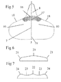
- a racing saddle ( Fig. 3 ) is elongate and narrow and the maximum width E-F is relatively small.
- the saddle nose and the seat part form an uninterrupted unit and the contact points of the sit bones G and H even fall completely outside the saddle surface area, as a result of which the body weight will press mainly on the perineal zone and more specifically on the pubic bone symphysis (4), resulting in saddle soreness.
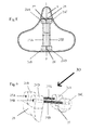
- the supporting saddle plate (15) has an inclined profile in the longitudinal direction.
- the rear edge (12) in this case forms the highest point and the saddle nose (8) the lowest point of the saddle plate (15), with an angle of inclination "beta” which is preferably between 8 and 14 and in particular 11 degrees.
- This inclined profile induces a slightly forward bent body posture, as a result of which a larger part of the body weight is transferred to the handlebars which leads to another reduction in the load on the posterior.
- the resulting forward tilt of the pelvis reduces the curvature of the back, relieves the lumbar vertebrae, reduces the strain on the ligaments and prevents lower back pain.
- the saddle surface with an elastic cushion or padding (14) which distributes the pressure of the posterior on the saddle better and reduces the local point load.
- the saddle plate (15) is covered in accordance with the prior art with a flexible and resilient padding (14) which has been additionally thickened at the location of the sensitive zones of the sit bones (10), the symphysis of the pubic bone (crotch) (17), the contact point of the front saddle edge with the hamstring tendon (9) and the tailbone (coccyx) (19).
- the surface profile of the padding (11) and of the supporting saddle plate (15) together determine the shape and thickness of the padding (14).
- the padding (14) of the proposed design has a bump-shaped relief elevation (16), which is situated in the transition zone between the saddle nose (8) and the seat part (7).
- This tendency of the posterior to slide off forwards is caused by the forward inclined saddle profile.
- This local bump-shaped relief elevation (16) corresponding to the hatched section in Fig. 5 is situated symmetrically with respect to the longitudinal axis of the saddle I-J, but is missing at the location of the contact point with the hamstring tendon (18) so as not to obstruct the pedalling movement of the legs during cycling.
- This bump-shaped relief elevation (16) of the padding (14) thus forms a kind of "ski jump” or "parapet” which prevents the posterior from moving in the forward direction and does not exert painful pressure on the pubic bone, due to the elasticity and thickness of the padding.
- the padding (14) moreover increases the feeling of comfort and improves the suspension.
- a bicycle saddle is not only a static design intended to provide optimum sitting comfort, but also and mainly a dynamic object, with the locomotion and the freedom of movement of the legs being most important.
- the front saddle edge (9) shows a gently inclined and rounded profile, without protrusions, ribs or crests which could impede the pedalling movement of the legs.
- the cross section taken halfway along the longitudinal axis of the saddle usually has a convex shape with sloping side edges (21) with the longitudinal axis of the saddle (20) forming the highest point.
- the more modern saddle type ( Fig. 7 ) has a central crest (22) in the longitudinal direction and two biconcave depressions (23) in the seat part (7), which results in an increased pressure on the perineum.
- this biconcave saddle shape impedes the lateral freedom of movement of the posterior, resulting in reduced circulation of the tissues and saddle soreness.
- the upper surface of the saddle has a virtually flat relief in the transverse direction, with the side edges remaining at virtually the same height as the central part of the saddle, so that the perineum is relieved.
- the pressure is distributed more towards the sides and the rear edge of the saddle and this reduces the pressure on the perineum and consequently also the risk of saddle soreness.
- the saddle nose (8) is indispensible for maintaining balance, for the steerability and the stability during cycling, particularly when going through bends and looking backwards.
- the saddle nose which does not have any supporting function otherwise, preferably has a length of between 6 and 12 cm and in particular of 9 cm. Due to this relatively short and narrow saddle nose in the proposed design, there is very little contact between the inside of the thighs and the sides of the saddle nose during cycling, as a result of which friction, waste of energy, heat and skin damage are prevented, even at elevated pedalling frequencies.
- the proposed design shows a securing rail comprising two separate straight bars (25A and 25B), the four ends of which are each separately contained (fixedly secured) in separate elastomer blocks (26A, 26B, 26C and 26D). These four elastomer blocks (26A, 26B, 26C and 26D) are situated in a common plane and are symmetrical and parallel with respect to the longitudinal axis 1-J of the saddle.
- the saddle can moreover be positioned slightly higher, as a result of which the legs are stretched further and the force efficiency is improved.
- the elastomer blocks (26A, 26B, 26C and 26D) are arranged in pairs on common bases (27 and 28) which are themselves attached to the underside of the saddle plate, in which the one common base (27) with the two front elastomer blocks (26A and 26C) is attached at the location of the saddle nose and the other common base (28) with the two rear elastomer blocks (26B and 26D) is attached at the location of the rear saddle edge.
- the elastomer blocks (26A, 26B, 26C and 26D) are compressed in a vertical direction, resulting in a shock-absorbing effect, in which case the entire saddle moves up and down in an even manner without a change in the angle of inclination of the saddle and therefore without any additional load on the perineal zone and the pubic bone symphysis.
- the underside of the saddle has a vertical transverse profile (29), situated at right angles to the longitudinal axis I-J of the saddle, wherein this transverse profile (29), on the one hand, prevents the displacement of the first and third elastomer blocks (front two elastomer blocks 26A and 26C) in the forward direction, but on the other hand is not fixedly connected thereto (but may be in contact therewith), so that the movement of the first and third elastomer blocks (front two elastomer blocks 26A and 26C) in the transverse direction is not impeded.
Landscapes
- Engineering & Computer Science (AREA)
- Mechanical Engineering (AREA)
- Professional, Industrial, Or Sporting Protective Garments (AREA)
- Motorcycle And Bicycle Frame (AREA)
- Seats For Vehicles (AREA)
Applications Claiming Priority (2)
| Application Number | Priority Date | Filing Date | Title |
|---|---|---|---|
| BE2010/0202A BE1019264A3 (nl) | 2010-03-26 | 2010-03-26 | Ergonomisch fietszadel. |
| BE201000446 | 2010-07-19 |
Publications (2)
| Publication Number | Publication Date |
|---|---|
| EP2371685A2 true EP2371685A2 (de) | 2011-10-05 |
| EP2371685A3 EP2371685A3 (de) | 2012-10-17 |
Family
ID=44167967
Family Applications (1)
| Application Number | Title | Priority Date | Filing Date |
|---|---|---|---|
| EP11158610A Withdrawn EP2371685A3 (de) | 2010-03-26 | 2011-03-17 | Ergonomischer Fahrradsattel und Befestigungssystem für einen solchen |
Country Status (1)
| Country | Link |
|---|---|
| EP (1) | EP2371685A3 (de) |
Citations (23)
| Publication number | Priority date | Publication date | Assignee | Title |
|---|---|---|---|---|
| US660215A (en) | 1898-05-21 | 1900-10-23 | Orville S Harmon | Bicycle-saddle. |
| GB190806596A (en) | 1908-03-25 | 1909-01-21 | John Boultbee Brooks | Improvements in Cycle Saddle Under Framings. |
| US1977962A (en) | 1933-12-28 | 1934-10-23 | Closure Service Company | Tamperproof seal for bottles |
| US2169105A (en) | 1938-04-22 | 1939-08-08 | Troxel Mfg Company | Bicycle saddle |
| US2225316A (en) | 1937-06-28 | 1940-12-17 | Mesinger Frederick | Resilient support for cycle saddles |
| US2331213A (en) | 1941-05-15 | 1943-10-05 | Mesinger Henry | Cycle saddle |
| GB861994A (en) | 1959-01-01 | 1961-03-01 | J B Brooks & Company Ltd | Improvements relating to under supports for the tops of cycle saddles |
| US3884525A (en) | 1972-11-10 | 1975-05-20 | Robert H Mesinger | Bicycle seat structure |
| US4773705A (en) | 1987-06-22 | 1988-09-27 | Terranova Joseph M | Bicycle seat |
| US4850643A (en) | 1988-03-07 | 1989-07-25 | Rollman Bruce L | Bicycle seat |
| US6045180A (en) | 1996-06-07 | 2000-04-04 | Harrodon Holdings Limited | Cycle seat |
| US6149230A (en) | 1999-09-09 | 2000-11-21 | Trek Bicycle Corporation | Bicycle saddle |
| US6343836B1 (en) | 2000-02-14 | 2002-02-05 | Tsai-Yun Yu | Bicycle saddle having an improved shock absorber |
| US6402236B1 (en) | 2000-04-10 | 2002-06-11 | Paul M. Yates | Split rail bicycle saddle |
| US6443524B1 (en) | 2001-05-07 | 2002-09-03 | Tsai-Yun Yu | Bicycle saddle having a shock-absorbing structure |
| US6523891B1 (en) | 2001-07-11 | 2003-02-25 | Paul M. Yates | Multi-shell bicycle saddle |
| US6886887B2 (en) | 2003-08-27 | 2005-05-03 | Tsai-Yun Yu | Bicycle saddle |
| DE202005013749U1 (de) | 2005-08-31 | 2005-11-17 | Sq-Lab Gmbh | Ergonomischer Sattel für Zweiräder zur Druckentlastung und automatischen Anpassung an den Sitzknochenabstand |
| US7083229B2 (en) | 2004-05-21 | 2006-08-01 | Janice Story Cope | Bicycle seat |
| DE202007008321U1 (de) | 2007-06-14 | 2007-08-23 | Sq-Lab Gmbh | Ergonomischer Sattel für Zweiräder zur Druckentlastung und automatischen Anpassung an den Sitzknochenabstand II |
| US7475940B2 (en) | 2004-08-06 | 2009-01-13 | M. D'a. Francesco Riondato | Support rail for a bicycle saddle shell |
| US7628451B2 (en) | 2005-11-25 | 2009-12-08 | Louis Chuang | Bicycle saddle |
| US7699391B2 (en) | 2004-08-11 | 2010-04-20 | Francesco Riondato | Bicycle saddle |
Family Cites Families (4)
| Publication number | Priority date | Publication date | Assignee | Title |
|---|---|---|---|---|
| US749865A (en) * | 1904-01-19 | John jaevis | ||
| US603943A (en) * | 1898-05-10 | Walter clifford | ||
| US5911473A (en) * | 1998-01-29 | 1999-06-15 | Hill; James D. | Bicycle saddle |
| US6652025B2 (en) * | 2001-10-09 | 2003-11-25 | Douglas Lyle Sylvester | Bicycle seat |
-
2011
- 2011-03-17 EP EP11158610A patent/EP2371685A3/de not_active Withdrawn
Patent Citations (24)
| Publication number | Priority date | Publication date | Assignee | Title |
|---|---|---|---|---|
| US660215A (en) | 1898-05-21 | 1900-10-23 | Orville S Harmon | Bicycle-saddle. |
| GB190806596A (en) | 1908-03-25 | 1909-01-21 | John Boultbee Brooks | Improvements in Cycle Saddle Under Framings. |
| US1977962A (en) | 1933-12-28 | 1934-10-23 | Closure Service Company | Tamperproof seal for bottles |
| US2225316A (en) | 1937-06-28 | 1940-12-17 | Mesinger Frederick | Resilient support for cycle saddles |
| US2169105A (en) | 1938-04-22 | 1939-08-08 | Troxel Mfg Company | Bicycle saddle |
| US2331213A (en) | 1941-05-15 | 1943-10-05 | Mesinger Henry | Cycle saddle |
| GB861994A (en) | 1959-01-01 | 1961-03-01 | J B Brooks & Company Ltd | Improvements relating to under supports for the tops of cycle saddles |
| US3884525A (en) | 1972-11-10 | 1975-05-20 | Robert H Mesinger | Bicycle seat structure |
| US4773705A (en) | 1987-06-22 | 1988-09-27 | Terranova Joseph M | Bicycle seat |
| US4850643A (en) | 1988-03-07 | 1989-07-25 | Rollman Bruce L | Bicycle seat |
| US6045180A (en) | 1996-06-07 | 2000-04-04 | Harrodon Holdings Limited | Cycle seat |
| US6149230A (en) | 1999-09-09 | 2000-11-21 | Trek Bicycle Corporation | Bicycle saddle |
| US6343836B1 (en) | 2000-02-14 | 2002-02-05 | Tsai-Yun Yu | Bicycle saddle having an improved shock absorber |
| US6402236B1 (en) | 2000-04-10 | 2002-06-11 | Paul M. Yates | Split rail bicycle saddle |
| US6443524B1 (en) | 2001-05-07 | 2002-09-03 | Tsai-Yun Yu | Bicycle saddle having a shock-absorbing structure |
| US6523891B1 (en) | 2001-07-11 | 2003-02-25 | Paul M. Yates | Multi-shell bicycle saddle |
| US6886887B2 (en) | 2003-08-27 | 2005-05-03 | Tsai-Yun Yu | Bicycle saddle |
| US7083229B2 (en) | 2004-05-21 | 2006-08-01 | Janice Story Cope | Bicycle seat |
| US7475940B2 (en) | 2004-08-06 | 2009-01-13 | M. D'a. Francesco Riondato | Support rail for a bicycle saddle shell |
| US7699391B2 (en) | 2004-08-11 | 2010-04-20 | Francesco Riondato | Bicycle saddle |
| DE202005013749U1 (de) | 2005-08-31 | 2005-11-17 | Sq-Lab Gmbh | Ergonomischer Sattel für Zweiräder zur Druckentlastung und automatischen Anpassung an den Sitzknochenabstand |
| US7628451B2 (en) | 2005-11-25 | 2009-12-08 | Louis Chuang | Bicycle saddle |
| DE202007008321U1 (de) | 2007-06-14 | 2007-08-23 | Sq-Lab Gmbh | Ergonomischer Sattel für Zweiräder zur Druckentlastung und automatischen Anpassung an den Sitzknochenabstand II |
| EP2003046A2 (de) | 2007-06-14 | 2008-12-17 | SQ-lab GmbH | Ergonomischer Sattel für Zweiräder zur Druckentlastung und automatischen Anpassung an den Sitzknochenabstand |
Also Published As
| Publication number | Publication date |
|---|---|
| EP2371685A3 (de) | 2012-10-17 |
Similar Documents
| Publication | Publication Date | Title |
|---|---|---|
| US7699391B2 (en) | Bicycle saddle | |
| RU2448860C2 (ru) | Седло велосипеда | |
| US5076642A (en) | Saddle for cycles | |
| US20070108808A1 (en) | Bicycle saddle | |
| TW201343455A (zh) | 自行車座墊 | |
| KR102109534B1 (ko) | 자전거 안장 | |
| KR20000016411A (ko) | 자전거 안장 | |
| US20070252419A1 (en) | Seating Mechanism and Chair | |
| US9688329B2 (en) | Ergonomic seat for a cycle | |
| CN211068928U (zh) | 下半身运动器械 | |
| EP2371685A2 (de) | Ergonomischer Fahrradsattel und Befestigungssystem für einen solchen | |
| US20040113470A1 (en) | Prostate protecting bicycle seat | |
| CN205113523U (zh) | 蝶形中凹的自行车鞍座 | |
| WO2001000061A1 (en) | An improved open-angle seat for a chair | |
| BE1019264A3 (nl) | Ergonomisch fietszadel. | |
| JP3654765B2 (ja) | 着座具 | |
| KR20090025825A (ko) | 안장 | |
| KR101048990B1 (ko) | 자전거 안장 | |
| TWI375632B (en) | Bicycle saddle | |
| KR20240153690A (ko) | 시트 구조물 | |
| EP1813514A2 (de) | Fahrradsattel | |
| KR20240031483A (ko) | 시트 구조물 | |
| KR101589833B1 (ko) | 요통 완화 의류 | |
| RU9686U1 (ru) | Безопорное для позвоночника средство расположения тела человека | |
| WO2014115083A1 (en) | Ergonomic bicycle seatboard for the glutei |
Legal Events
| Date | Code | Title | Description |
|---|---|---|---|
| PUAI | Public reference made under article 153(3) epc to a published international application that has entered the european phase |
Free format text: ORIGINAL CODE: 0009012 |
|
| AK | Designated contracting states |
Kind code of ref document: A2 Designated state(s): AL AT BE BG CH CY CZ DE DK EE ES FI FR GB GR HR HU IE IS IT LI LT LU LV MC MK MT NL NO PL PT RO RS SE SI SK SM TR |
|
| AX | Request for extension of the european patent |
Extension state: BA ME |
|
| PUAL | Search report despatched |
Free format text: ORIGINAL CODE: 0009013 |
|
| AK | Designated contracting states |
Kind code of ref document: A3 Designated state(s): AL AT BE BG CH CY CZ DE DK EE ES FI FR GB GR HR HU IE IS IT LI LT LU LV MC MK MT NL NO PL PT RO RS SE SI SK SM TR |
|
| AX | Request for extension of the european patent |
Extension state: BA ME |
|
| RIC1 | Information provided on ipc code assigned before grant |
Ipc: B62J 1/00 20060101AFI20120912BHEP Ipc: B62J 1/08 20060101ALI20120912BHEP |
|
| 17P | Request for examination filed |
Effective date: 20130416 |
|
| STAA | Information on the status of an ep patent application or granted ep patent |
Free format text: STATUS: THE APPLICATION IS DEEMED TO BE WITHDRAWN |
|
| 18D | Application deemed to be withdrawn |
Effective date: 20151001 |