EP2371585B1 - Tire tread construction for improved traction - Google Patents
Tire tread construction for improved traction Download PDFInfo
- Publication number
- EP2371585B1 EP2371585B1 EP11159895A EP11159895A EP2371585B1 EP 2371585 B1 EP2371585 B1 EP 2371585B1 EP 11159895 A EP11159895 A EP 11159895A EP 11159895 A EP11159895 A EP 11159895A EP 2371585 B1 EP2371585 B1 EP 2371585B1
- Authority
- EP
- European Patent Office
- Prior art keywords
- voids
- pedestal
- tire tread
- void
- radially
- Prior art date
- Legal status (The legal status is an assumption and is not a legal conclusion. Google has not performed a legal analysis and makes no representation as to the accuracy of the status listed.)
- Not-in-force
Links
Images

Classifications
-
- B—PERFORMING OPERATIONS; TRANSPORTING
- B60—VEHICLES IN GENERAL
- B60C—VEHICLE TYRES; TYRE INFLATION; TYRE CHANGING; CONNECTING VALVES TO INFLATABLE ELASTIC BODIES IN GENERAL; DEVICES OR ARRANGEMENTS RELATED TO TYRES
- B60C11/00—Tyre tread bands; Tread patterns; Anti-skid inserts
- B60C11/03—Tread patterns
- B60C11/032—Patterns comprising isolated recesses
-
- B—PERFORMING OPERATIONS; TRANSPORTING
- B60—VEHICLES IN GENERAL
- B60C—VEHICLE TYRES; TYRE INFLATION; TYRE CHANGING; CONNECTING VALVES TO INFLATABLE ELASTIC BODIES IN GENERAL; DEVICES OR ARRANGEMENTS RELATED TO TYRES
- B60C11/00—Tyre tread bands; Tread patterns; Anti-skid inserts
- B60C11/03—Tread patterns
- B60C11/0302—Tread patterns directional pattern, i.e. with main rolling direction
-
- B—PERFORMING OPERATIONS; TRANSPORTING
- B60—VEHICLES IN GENERAL
- B60C—VEHICLE TYRES; TYRE INFLATION; TYRE CHANGING; CONNECTING VALVES TO INFLATABLE ELASTIC BODIES IN GENERAL; DEVICES OR ARRANGEMENTS RELATED TO TYRES
- B60C11/00—Tyre tread bands; Tread patterns; Anti-skid inserts
- B60C11/03—Tread patterns
- B60C11/12—Tread patterns characterised by the use of narrow slits or incisions, e.g. sipes
- B60C11/1272—Width of the sipe
- B60C11/1281—Width of the sipe different within the same sipe, i.e. enlarged width portion at sipe bottom or along its length
-
- B—PERFORMING OPERATIONS; TRANSPORTING
- B60—VEHICLES IN GENERAL
- B60C—VEHICLE TYRES; TYRE INFLATION; TYRE CHANGING; CONNECTING VALVES TO INFLATABLE ELASTIC BODIES IN GENERAL; DEVICES OR ARRANGEMENTS RELATED TO TYRES
- B60C11/00—Tyre tread bands; Tread patterns; Anti-skid inserts
- B60C11/03—Tread patterns
- B60C11/12—Tread patterns characterised by the use of narrow slits or incisions, e.g. sipes
- B60C11/1236—Tread patterns characterised by the use of narrow slits or incisions, e.g. sipes with special arrangements in the tread pattern
- B60C2011/1254—Tread patterns characterised by the use of narrow slits or incisions, e.g. sipes with special arrangements in the tread pattern with closed sipe, i.e. not extending to a groove
Definitions
- the present invention relates to a tire tread, a pneumatic tire having a tread pattern, and more particularly, a pneumatic tire having blocks and constructions in the blocks for improving traction of the tread.
- the invention also relates to a tread molding element for molding a structure in a tire tread.
- a conventional pneumatic tire may have sipes in tread blocks so that the running performance of the tire improves on ice- or snow-covered roads due to the edges of the sipes (known as a studless tire).
- the studless tire may be used on vehicles which run on ice- or snow-covered roads.
- groove width of a sipe is narrow, when the sipe opens, it is easy for stress to concentrate on the bottom portion of the sipe. It is therefore easy for cracks to form from the bottom portion of the sipe.
- an enlarged portion, having a circular cross-sectional configuration, at the bottom portion of a sipe may be formed.
- the rubber which should be between the sipes, may be caught and remain between blades of a vulcanization mold.
- the rigidity of the narrow area between the sipes may decrease and the amount of shearing deformation, when the pneumatic tire is subject to a front-to-back force during running, may increase. Thus, cracks may form at the bottom portion of the sipe.
- Conventional blocks may have at least two sipes.
- side force is applied to narrow areas due to cornering or the like, distortion due to shearing occurs, and cracks form in the bottoms of the sipes. If the cracks worsen, depending on the case, the narrow areas may break off.
- the bottom portion of the narrow area may be deformed by shearing force in the transverse direction. Again, cracks are generated, and, depending on the case, the narrow area may break off.
- concave portions for forming blocks are provided in a vulcanization mold for vulcanizing a block tire. After an unvulcanized green tire is placed in the vulcanization mold, the green tire is pressurized to a predetermined pressure and heated to a predetermined temperature. Due to this process, the rubber of the green tire is pressed tightly into the concave portions so that the outer contour is formed and vulcanization is effected.
- vent holes which communicate with the outside air, may be provided in vicinities of the four corners of the concave portion so that the air within the cavities may escape and the rubber may flow more easily.
- the concave portion may be divided into three areas by the pair of blades so that a small concave portion may be formed between the pair of blades.
- one conventional method forms a pneumatic tire by using a vulcanization mold in which through-holes are provided so that the small concave portion and end concave portions, which are adjacent to the small concave portion, communicate via the through-holes.
- this structure does not sufficiently allow the air inside the small concave portion to escape, and consequently does not sufficiently prevent the formation of bare areas.
- a conventional pneumatic tire as the tire becomes worn, may prevent the protruding of a narrow area interposed between sipes so that the on-ice running performance of the tire does not deteriorate.
- the conventional tire may have blocks with at least one pair of sipes and which may reliably and easily be removed from a mold for vulcanization.
- the tire may have blocks with at least one pair of sipes in which the generation of cracks at bottom portions of the sipes may be prevented.
- the tire may further have a block pattern capable of preventing the formation of cracks in a narrow area defined by a pair of sipes and the breaking off of portions of blocks.
- a mold for vulcanization of the conventional tire may prevent the formation of bare areas in a narrow area when the pneumatic tire is manufactured.
- the conventional pneumatic tire may comprise a plurality of blocks, each having a narrow area interposed between one set of two sipes which extend substantially in a transverse direction of the tire and wide areas positioned respectively at both sides of the narrow area across the sipes.
- the narrow area may intermittently slidingly contact the road surface and not contact the road surface.
- the narrow area may wear more quickly than the wide areas due to the narrow areas slidingly contacting the road surface. Therefore, the narrow area does not protrude compared with the wide areas.
- the rigidity of the narrow area may not be as small as that of the wide area.
- Another conventional pneumatic tire may comprise a plurality of blocks, each having a narrow area interposed between one set of sipes which extend substantially in transverse direction of the tire and wide areas positioned respectively at both sides of the narrow area across the sipes, expanded portions being formed respectively at bottom portions of the sipes.
- EP-A1 630 008 describes a tire tread and a tread molding element in accordance in the preamble of claims 1 and 14 respectively.
- EP-A1 066 991 describes a wear indicator for a tire wherein a surface of the tread in contact with the road surface is provided with indicators indicating the momentary groove depth of the tire.
- DE-A-44 26 950 describes a tire tread comprising ring-shaped incisions in the tread. Such incisions are also known from EP-A- 0 664 230 .
- the invention relates to a tire in accordance with claim 1, a tire in accordance with claim 13, and a tread molding element in accordance with claim 14.
- a structure for a tread pattern of a pneumatic tire in accordance with the present invention includes a radially extending pedestal, a first set of preferably cylindrical voids extending radially through the pedestal, a second set of preferably cylindrical voids extending radially through the pedestal, and a radially extending void ring circumscribing the pedestal.
- the pedestal has a rounded-off triangular shape.
- the pedestal has a circular shape.
- the pedestal has a rounded-off three-pronged shape.
- the first set includes three cylindrical voids.
- the second set includes three cylindrical voids.
- the first set of cylindrical voids each have a first spherical expansion at the radially innermost portion of the cylindrical void and a second spherical expansion interposed between the first spherical expansion and the radially outermost portion of the cylindrical void.
- each of the first set of cylindrical voids is defined by a partially spherical expansion.
- the second set of cylindrical voids each have a first spherical expansion disposed radially away from a radially inner end of the cylindrical void and a second spherical expansion interposed between the first spherical expansion and the radially outermost portion of the cylindrical void.
- each of the second set of cylindrical voids is defined by a partially spherical expansion.
- the pedestal is radially compressed against a road surface and, if present, an ice layer during rotation of the pneumatic tire.
- the pedestal is deformed to extend beyond a main tread surface of the pneumatic tire.
- biting edges of the pedestal enhance snow traction of the pneumatic tire.
- the structures create suction against an ice surface for enhancing ice traction.
- a portion of snow is ejected by the elastic expansion of the pedestal.
- FIG. 2 is a radial top view of an example structure 100 in the tread pattern 10 in accordance with the present invention.
- the structure 100 includes a rounded-off triangular pedestal 110 defined by a first set of three cylindrical voids 111, a second set of three cylindrical voids 122, and a void ring 133 circumscribing the pedestal ( FIG. 5 ).
- the first set of cylindrical voids 111 each have a first spherical expansion 113 at the radially innermost portion of the cylindrical void and a second spherical expansion 115 interposed between the first spherical expansion and the radially outermost portion of the cylindrical void.
- the radially outermost portion of each cylindrical void 111 is defined by a partially spherical (i.e., hemispherical) expansion 117.
- the second set of cylindrical voids 122 each have a first spherical expansion 123 disposed radially away from a radially inner end of the cylindrical void and a second spherical expansion 125 interposed between the first spherical expansion and the radially outermost portion of the cylindrical void.
- the radially outermost portion of each cylindrical void 122 is defined by a partially spherical (i.e., hemispherical) expansion 127.
- FIG. 3 is a radial top view of another example structure 200 in the tread pattern 10 in accordance with the present invention.
- the structure 200 includes a circular pedestal 210 defined by a first set of three cylindrical voids 211, a second set of three cylindrical voids 222, and a void ring 233 circumscribing the pedestal ( FIG. 5 ).
- the first set of cylindrical voids 211 each have a first spherical expansion 213 at the radially innermost portion of the cylindrical void and a second spherical expansion 215 interposed between the first spherical expansion and the radially outermost portion of the cylindrical void.
- the radially outermost portion of each cylindrical void 211 is defined by a partially spherical (i.e., hemispherical) expansion 217.
- the second set of cylindrical voids 222 each have a first spherical expansion 223 disposed radially away from a radially inner end of the cylindrical void and a second spherical expansion 225 interposed between the first spherical expansion and the radially outermost portion of the cylindrical void.
- the radially outermost portion of each cylindrical void 222 is defined by a partially spherical (i.e., hemispherical) expansion 227.
- FIG. 4 is a radial top view of another example structure 300 in the tread pattern 10 in accordance with the present invention.
- the structure 300 includes a rounded-off three-pronged pedestal 310 defined by a first set of three cylindrical voids 311, a second set of three cylindrical voids 322, and a void ring 333 circumscribing the pedestal ( FIG. 6 ).
- the first set of cylindrical voids 311 each have a first spherical expansion 313 at the radially innermost portion of the cylindrical void and a second spherical expansion 315 interposed between the first spherical expansion and the radially outermost portion of the cylindrical void.
- the radially outermost portion of each cylindrical void 311 is defined by a partially spherical (i.e., hemispherical) expansion 317.
- the second set of cylindrical voids 322 each have a first spherical expansion 323 disposed radially away from a radially inner end of the cylindrical void and a second spherical expansion 325 interposed between the first spherical expansion and the radially outermost portion of the cylindrical void.
- the radially outermost portion of each cylindrical void 322 is defined by a partially spherical (i.e., hemispherical) expansion 327.
- the shapes of the pedestals 110, 310 of FIGS. 2 and 4 mitigate twist of the pedestals thereby improving the handling compared with the circular pedestal 210 of FIG. 3 .
- the structures 100, 200, 300 enhance rubber elasticity adjacent the structures and within the structures. As shown in FIGS. 7-10 , when the structure 100, 200, or 300 is radially compressed against the road surface 1 and any ice layer 2, this contact area of rubber against road/ice increases ( FIG. 9 ) thereby breaking any water layer and avoiding sliding of the tread portion 10.
- the difference in temperature of the air within the structures 100, 200, or 300 and the road/ice surface 1, 2 itself may further increase the suction between the structures and the road/ice.
- the radially outward force created by the rotating tire may deform the relatively flexible pedestal 110, 210, or 310 to extend beyond the main tread surface 5.
- the biting edges of the pedestal may enhance snow traction and the closing off of the voids in the structures may create a suction against an ice surface for enhancing ice traction.
- any portion 3 of snow which was forced into the structure 100, 200, or 300 may be ejected by the elastic expansion of the pedestal ( FIG. 10 ).
- the present invention may be embodied in a variety of forms.
- a variety of configurations and dimensions can be used for the block of the pneumatic tire, and a variety of arrangements and combinations can also be used.
- the structure and elements of the tread are not limited to those described in the embodiments, and various structures and elements may be used in accordance with the appendent claims.
Description
- The present invention relates to a tire tread, a pneumatic tire having a tread pattern, and more particularly, a pneumatic tire having blocks and constructions in the blocks for improving traction of the tread. The invention also relates to a tread molding element for molding a structure in a tire tread.
- A conventional pneumatic tire may have sipes in tread blocks so that the running performance of the tire improves on ice- or snow-covered roads due to the edges of the sipes (known as a studless tire). The studless tire may be used on vehicles which run on ice- or snow-covered roads.
- Because groove width of a sipe is narrow, when the sipe opens, it is easy for stress to concentrate on the bottom portion of the sipe. It is therefore easy for cracks to form from the bottom portion of the sipe. In order to combat this drawback, an enlarged portion, having a circular cross-sectional configuration, at the bottom portion of a sipe may be formed. However, when two sipes are disposed so as to be adjacent to each other, if an interval between enlarged portions is too narrow, the rubber, which should be between the sipes, may be caught and remain between blades of a vulcanization mold. Further, the rigidity of the narrow area between the sipes may decrease and the amount of shearing deformation, when the pneumatic tire is subject to a front-to-back force during running, may increase. Thus, cracks may form at the bottom portion of the sipe.
- Conventional blocks may have at least two sipes. When side force is applied to narrow areas due to cornering or the like, distortion due to shearing occurs, and cracks form in the bottoms of the sipes. If the cracks worsen, depending on the case, the narrow areas may break off.
- However, when a side force occurs during running, such as that described above, and acts upon tires having a variety of configurations for blocks having sipes, the bottom portion of the narrow area may be deformed by shearing force in the transverse direction. Again, cracks are generated, and, depending on the case, the narrow area may break off.
- When the above-described blocks are disposed on a pneumatic tire tread such that the narrow areas are arranged in a row along the transverse direction of the tire, areas having low rigidity are conventionally arranged so as to coincide along the transverse direction of the tire. When a side force is applied to the pneumatic tire, the deformation of the narrow areas may be large and cracks may form in the narrow areas and the narrow areas may break off.
- Usually, concave portions for forming blocks are provided in a vulcanization mold for vulcanizing a block tire. After an unvulcanized green tire is placed in the vulcanization mold, the green tire is pressurized to a predetermined pressure and heated to a predetermined temperature. Due to this process, the rubber of the green tire is pressed tightly into the concave portions so that the outer contour is formed and vulcanization is effected.
- When internal pressure is applied to the green tire and rubber of the green tire is forced into a concave portion of the mold, the concave portion is closed by the rubber and air and gas generated by the rubber stagnate so that the rubber cannot flow. In order to prevent such a situation from occurring, vent holes, which communicate with the outside air, may be provided in vicinities of the four corners of the concave portion so that the air within the cavities may escape and the rubber may flow more easily. When a pair of sipes is provided so that the block is divided into three areas, it may be necessary to form a pair of thin, plate-shaped blades, which extend from one wall surface of the mold to the opposing wall surface, within the concave portion. The concave portion may be divided into three areas by the pair of blades so that a small concave portion may be formed between the pair of blades. When the rubber of the green tire flows into the concave portion, there is no place within the small convex portion for the air to escape so that the small concave portion may be closed by the rubber. Therefore, the rubber does not flow to the bottom portion of the small concave portion, and bare areas exist in the block after vulcanization.
- In order to eliminate this drawback, one conventional method forms a pneumatic tire by using a vulcanization mold in which through-holes are provided so that the small concave portion and end concave portions, which are adjacent to the small concave portion, communicate via the through-holes. However, this structure does not sufficiently allow the air inside the small concave portion to escape, and consequently does not sufficiently prevent the formation of bare areas.
- A conventional pneumatic tire, as the tire becomes worn, may prevent the protruding of a narrow area interposed between sipes so that the on-ice running performance of the tire does not deteriorate. The conventional tire may have blocks with at least one pair of sipes and which may reliably and easily be removed from a mold for vulcanization. The tire may have blocks with at least one pair of sipes in which the generation of cracks at bottom portions of the sipes may be prevented. The tire may further have a block pattern capable of preventing the formation of cracks in a narrow area defined by a pair of sipes and the breaking off of portions of blocks. A mold for vulcanization of the conventional tire may prevent the formation of bare areas in a narrow area when the pneumatic tire is manufactured.
- The conventional pneumatic tire may comprise a plurality of blocks, each having a narrow area interposed between one set of two sipes which extend substantially in a transverse direction of the tire and wide areas positioned respectively at both sides of the narrow area across the sipes. As the tire contacts the ground during rotation, due to the difference between the distance from the center of rotation of the tire to the tread surface of the narrow area and the distance from the center of rotation of the tire to the tread surface of the wide area, the narrow area may intermittently slidingly contact the road surface and not contact the road surface. Thus, the narrow area may wear more quickly than the wide areas due to the narrow areas slidingly contacting the road surface. Therefore, the narrow area does not protrude compared with the wide areas. The rigidity of the narrow area may not be as small as that of the wide area.
- Another conventional pneumatic tire may comprise a plurality of blocks, each having a narrow area interposed between one set of sipes which extend substantially in transverse direction of the tire and wide areas positioned respectively at both sides of the narrow area across the sipes, expanded portions being formed respectively at bottom portions of the sipes. By providing the expanded portions at the bottom portions of the sipes, the stress applied to the bottom portions when the sipes open may be dispersed, and the formation of cracks from the bottom portions may be prevented. Therefore, when the pneumatic tire is removed from the vulcanization mold used to form the pneumatic tire, the narrow area is hot caught and does not remain between blades of the vulcanization mold which are used to form the sipes.
-
EP-A1 630 008 -
EP-A1 066 991 -
DE-A-44 26 950 describes a tire tread comprising ring-shaped incisions in the tread. Such incisions are also known fromEP-A- 0 664 230 . - The invention relates to a tire in accordance with claim 1, a tire in accordance with claim 13, and a tread molding element in accordance with claim 14.
- Dependent claims refer to preferred embodiments of the invention.
- A structure for a tread pattern of a pneumatic tire in accordance with the present invention includes a radially extending pedestal, a first set of preferably cylindrical voids extending radially through the pedestal, a second set of preferably cylindrical voids extending radially through the pedestal, and a radially extending void ring circumscribing the pedestal.
- In accordance with one aspect of the present invention, the pedestal has a rounded-off triangular shape.
- In accordance with another aspect of the present invention, the pedestal has a circular shape.
- In accordance with yet another aspect of the present invention, the pedestal has a rounded-off three-pronged shape.
- In accordance with still another aspect of the present invention, the first set includes three cylindrical voids.
- In accordance with yet another aspect of the present invention, the second set includes three cylindrical voids.
- In accordance with still another aspect of the present invention, the first set of cylindrical voids each have a first spherical expansion at the radially innermost portion of the cylindrical void and a second spherical expansion interposed between the first spherical expansion and the radially outermost portion of the cylindrical void.
- In accordance with yet another aspect of the present invention, the radially outermost portion of each of the first set of cylindrical voids is defined by a partially spherical expansion.
- In accordance with still another aspect of the present invention, the second set of cylindrical voids each have a first spherical expansion disposed radially away from a radially inner end of the cylindrical void and a second spherical expansion interposed between the first spherical expansion and the radially outermost portion of the cylindrical void.
- In accordance with yet another aspect of the present invention, the radially outermost portion of each of the second set of cylindrical voids is defined by a partially spherical expansion.
- In accordance with still another aspect of the present invention, the pedestal is radially compressed against a road surface and, if present, an ice layer during rotation of the pneumatic tire.
- In accordance with yet another aspect of the present invention, the pedestal is deformed to extend beyond a main tread surface of the pneumatic tire.
- In accordance with still another aspect of the present invention, biting edges of the pedestal enhance snow traction of the pneumatic tire.
- In accordance with yet another aspect of the present invention, the structures create suction against an ice surface for enhancing ice traction.
- In accordance with still another aspect of the present invention, a portion of snow is ejected by the elastic expansion of the pedestal.
- The invention will be described by way of example and with reference to the accompanying drawings in which:
-
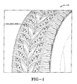
FIG. 1 is a schematic perspective view illustrating a portion of a tread pattern of a pneumatic tire having structures in accordance with the present invention. -
FIG. 2 is a schematic top view of one example structure for use in the tread pattern ofFIG. 1 in accordance with the present invention. -
FIG. 3 is a schematic top view of another example structure for use in the tread pattern ofFIG. 1 in accordance with the present invention. -
FIG. 4 is a schematic top view of another example structure for use in the tread pattern ofFIG. 1 in accordance with the present invention. -
FIG. 5 is a schematic section view taken along lines 5-5 inFIG. 2 or FIG. 3 . -
FIG. 6 is a schematic section view taken along lines 6-6 inFIG. 4 . -
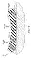
FIG. 7 is a schematic side view of the tread pattern ofFIG. 1 under an operating condition. -
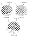
FIG. 8 is a detail view of one structure ofFIG. 7 . -
FIG. 9 is a detail view of another structure ofFIG. 7 . -
FIG. 10 is a detail view of another structure ofFIG. 7 . - A pneumatic tire in accordance with the present invention has a
tread pattern 10, a portion of which is illustrated inFIG. 1 .FIG. 2 is a radial top view of anexample structure 100 in thetread pattern 10 in accordance with the present invention. Thestructure 100 includes a rounded-offtriangular pedestal 110 defined by a first set of threecylindrical voids 111, a second set of threecylindrical voids 122, and avoid ring 133 circumscribing the pedestal (FIG. 5 ). - The first set of
cylindrical voids 111 each have a first spherical expansion 113 at the radially innermost portion of the cylindrical void and a second spherical expansion 115 interposed between the first spherical expansion and the radially outermost portion of the cylindrical void. The radially outermost portion of eachcylindrical void 111 is defined by a partially spherical (i.e., hemispherical) expansion 117. - The second set of
cylindrical voids 122 each have a first spherical expansion 123 disposed radially away from a radially inner end of the cylindrical void and a second spherical expansion 125 interposed between the first spherical expansion and the radially outermost portion of the cylindrical void. The radially outermost portion of eachcylindrical void 122 is defined by a partially spherical (i.e., hemispherical) expansion 127. -
FIG. 3 is a radial top view of anotherexample structure 200 in thetread pattern 10 in accordance with the present invention. Thestructure 200 includes acircular pedestal 210 defined by a first set of threecylindrical voids 211, a second set of threecylindrical voids 222, and avoid ring 233 circumscribing the pedestal (FIG. 5 ). - The first set of
cylindrical voids 211 each have a first spherical expansion 213 at the radially innermost portion of the cylindrical void and a second spherical expansion 215 interposed between the first spherical expansion and the radially outermost portion of the cylindrical void. The radially outermost portion of eachcylindrical void 211 is defined by a partially spherical (i.e., hemispherical) expansion 217. - The second set of
cylindrical voids 222 each have a first spherical expansion 223 disposed radially away from a radially inner end of the cylindrical void and a second spherical expansion 225 interposed between the first spherical expansion and the radially outermost portion of the cylindrical void. The radially outermost portion of eachcylindrical void 222 is defined by a partially spherical (i.e., hemispherical) expansion 227. -
FIG. 4 is a radial top view of anotherexample structure 300 in thetread pattern 10 in accordance with the present invention. Thestructure 300 includes a rounded-off three-pronged pedestal 310 defined by a first set of threecylindrical voids 311, a second set of threecylindrical voids 322, and avoid ring 333 circumscribing the pedestal (FIG. 6 ). - The first set of
cylindrical voids 311 each have a firstspherical expansion 313 at the radially innermost portion of the cylindrical void and a secondspherical expansion 315 interposed between the first spherical expansion and the radially outermost portion of the cylindrical void. The radially outermost portion of eachcylindrical void 311 is defined by a partially spherical (i.e., hemispherical)expansion 317. - The second set of
cylindrical voids 322 each have a firstspherical expansion 323 disposed radially away from a radially inner end of the cylindrical void and a secondspherical expansion 325 interposed between the first spherical expansion and the radially outermost portion of the cylindrical void. The radially outermost portion of eachcylindrical void 322 is defined by a partially spherical (i.e., hemispherical)expansion 327. - The shapes of the
pedestals FIGS. 2 and 4 mitigate twist of the pedestals thereby improving the handling compared with thecircular pedestal 210 ofFIG. 3 . Thestructures FIGS. 7-10 , when thestructure ice layer 2, this contact area of rubber against road/ice increases (FIG. 9 ) thereby breaking any water layer and avoiding sliding of thetread portion 10. The difference in temperature of the air within thestructures ice surface 1, 2 itself may further increase the suction between the structures and the road/ice. - As shown in
FIG. 8 , the radially outward force created by the rotating tire may deform the relativelyflexible pedestal main tread surface 5. When thepedestal FIG. 9 ), the biting edges of the pedestal may enhance snow traction and the closing off of the voids in the structures may create a suction against an ice surface for enhancing ice traction. When thepedestal portion 3 of snow which was forced into thestructure FIG. 10 ). - The present invention may be embodied in a variety of forms. For example, a variety of configurations and dimensions can be used for the block of the pneumatic tire, and a variety of arrangements and combinations can also be used. Further, the structure and elements of the tread are not limited to those described in the embodiments, and various structures and elements may be used in accordance with the appendent claims.
Claims (14)
- A tire tread comprising a structure (100, 200, 300), the structure (100, 200, 300) comprising a radially extending pedestal (110, 210, 310), a first set of voids (111, 211, 311) extending radially through the pedestal (110, 210, 310), a second set of voids (122, 222, 322) extending radially through the pedestal (110, 210, 310); and a radially extending void ring (133, 233, 333) circumscribing the pedestal (110, 210, 310), characterized in that the first set of voids (111, 211, 311) and the second set of voids (122, 222, 322) are cylindrical voids and/or arranged symmetrically within the void ring (133, 233, 333) with respect to a center of the void ring (133, 233, 333).
- The tire tread as set forth in claim 1 wherein the pedestal (110, 210, 310) has a rounded-off triangular, pentagonal or hexagonal shape.
- The tire tread as set forth in claim 1 wherein the pedestal (110, 210, 310) has a circular shape.
- The tire tread as set forth in claim 1 wherein the pedestal (110, 210, 310) has a rounded-off three-pronged shape.
- The tire tread as set forth in at least one of the previous claims wherein the first set of voids (111, 211, 311) includes two or three cylindrical voids, and/or wherein the second set of voids includes two or three cylindrical voids.
- The tire tread as set forth in at least one of the previous claims wherein the first set of voids (111, 211, 311) each have a first spherical expansion at the radially innermost portion of the cylindrical void and a second spherical expansion interposed between the first spherical expansion and the radially outermost portion of the cylindrical void.
- The tire tread as set forth in claim 6 wherein the radially outermost portion of each of the first set of cylindrical voids (111, 211, 311) is defined by a partially spherical expansion.
- The tire tread as set forth in at least one of the previous claims wherein the second set of cylindrical voids (122, 222, 322) each have a first spherical expansion disposed radially away from a radially inner end of the cylindrical void and a second spherical expansion interposed between the first spherical expansion and the radially outermost portion of the cylindrical void.
- The tire tread as set forth in claim 8 wherein the radially outermost portion of each of the second set of cylindrical voids (122, 222, 322) is defined by a partially spherical expansion.
- The tire tread as set forth in at least one of the previous claims wherein the pedestal (110, 210, 310) is located such that it is radially compressed against a road surface and, if present, an ice layer during rotation of a pneumatic tire comprising the tire tread (10).
- The tire tread as set forth in at least one of the previous claims wherein the first set of voids (111, 211, 311), the second set of voids (122, 222, 322) and the void ring (133, 233, 333) each extend from the tread surface to a radial depth in a range of from 4 to 9 mm.
- The tire tread as set forth in claim 11 wherein the first set of voids (111, 211, 311), the second set of voids (122, 222, 322) and the void ring (133, 233, 333) each extend from the tread surface to a radial depth in a range of from 4 to 7 mm.
- A pneumatic tire comprising a tire tread (10) in accordance with at least one of the previous claims.
- A tread molding element for molding a structure (100, 200, 300) into a tire tread (10) in accordance with at least one of the previous claims, the element comprising a first set of void blades extending radially through a pedestal (110, 210, 310), a second set of void blades extending radially through the pedestal (110, 210, 310), and a radially extending void ring blade circumscribing the pedestal (110, 210, 310), characterized in that the first set of voids and the second set of voids are cylindrical voids and/or arranged symmetrically within the void ring with respect to a center of the void ring.
Priority Applications (1)
| Application Number | Priority Date | Filing Date | Title |
|---|---|---|---|
| PL11159895T PL2371585T3 (en) | 2010-03-30 | 2011-03-25 | Tire tread construction for improved traction |
Applications Claiming Priority (1)
| Application Number | Priority Date | Filing Date | Title |
|---|---|---|---|
| US12/749,793 US8376007B2 (en) | 2010-03-30 | 2010-03-30 | Structure for tread pattern having void ring, pedestal and cylindrical voids |
Publications (2)
| Publication Number | Publication Date |
|---|---|
| EP2371585A1 EP2371585A1 (en) | 2011-10-05 |
| EP2371585B1 true EP2371585B1 (en) | 2013-01-23 |
Family
ID=44168970
Family Applications (1)
| Application Number | Title | Priority Date | Filing Date |
|---|---|---|---|
| EP11159895A Not-in-force EP2371585B1 (en) | 2010-03-30 | 2011-03-25 | Tire tread construction for improved traction |
Country Status (4)
| Country | Link |
|---|---|
| US (1) | US8376007B2 (en) |
| EP (1) | EP2371585B1 (en) |
| CN (1) | CN102205779B (en) |
| PL (1) | PL2371585T3 (en) |
Families Citing this family (6)
| Publication number | Priority date | Publication date | Assignee | Title |
|---|---|---|---|---|
| FR2995253B1 (en) * | 2012-09-13 | 2015-01-16 | Michelin & Cie | TIRE TREAD AND TIRE FOR HEAVY WEIGHT |
| CN104385857A (en) * | 2014-11-21 | 2015-03-04 | 双星东风轮胎有限公司 | Nail-embedded snow tire |
| FI127150B (en) * | 2017-01-18 | 2017-12-15 | Nokian Renkaat Oyj | Pattern bit arrangement for a pneumatic tire or wear band |
| US10682889B2 (en) | 2017-03-06 | 2020-06-16 | The Goodyear Tire & Rubber Company | Tire for autonomous vehicle |
| JP7200734B2 (en) * | 2019-02-19 | 2023-01-10 | 住友ゴム工業株式会社 | tire |
| JP7177008B2 (en) * | 2019-06-14 | 2022-11-22 | 株式会社ブリヂストン | pneumatic tire |
Family Cites Families (20)
| Publication number | Priority date | Publication date | Assignee | Title |
|---|---|---|---|---|
| GB546975A (en) * | 1941-02-04 | 1942-08-07 | Dunlop Rubber Co | Improvements in treads for pneumatic tyres |
| NL137253C (en) * | 1968-12-13 | |||
| US4221254A (en) * | 1978-02-14 | 1980-09-09 | The Goodyear Tire & Rubber Company | Tread for pneumatic tire |
| US4667719A (en) * | 1985-05-10 | 1987-05-26 | Koji Masuda | Non-skid ice and snow tread configuration for pneumatic vehicle tires |
| US5176765A (en) | 1988-04-13 | 1993-01-05 | Bridgestone Corporation | Pneumatic tire having outer tread layer of foam rubber |
| JPH02299910A (en) * | 1989-05-16 | 1990-12-12 | Bridgestone Corp | Pneumatic tire excellent in wet performance |
| JPH03239606A (en) * | 1990-02-16 | 1991-10-25 | Hishifusa Miura | Slip prevention mechanism for tire or the like |
| US5385189A (en) | 1991-11-01 | 1995-01-31 | Bridgestone Corporation | Pneumatic tire with paired sides in the tread |
| AT404244B (en) | 1994-01-20 | 1998-09-25 | Semperit Ag | VEHICLE TIRE WITH A TREAD |
| DE4426950A1 (en) | 1994-07-29 | 1996-02-01 | Continental Ag | Tyre tread profile for bus and truck tyres |
| US5785782A (en) | 1995-05-02 | 1998-07-28 | Tsuzuki Electric Corporation | Slip-preventing vehicle tire |
| JPH09303365A (en) * | 1996-05-20 | 1997-11-25 | Masao Wachi | Utilizing method of suction cup useful for preventing accident |
| FI112340B (en) | 1999-06-29 | 2003-11-28 | Nokian Renkaat Oyj | Vehicle tire tread with means for indicating at any instant the depth of the tread grooves |
| US7267148B2 (en) * | 1999-08-10 | 2007-09-11 | Michelin Recherche Et Technique S.A. | Measurement of adherence between a vehicle wheel and the roadway |
| JP3589644B2 (en) | 2000-12-07 | 2004-11-17 | 日本碍子株式会社 | Tire mold |
| ES2329018T3 (en) | 2001-09-28 | 2009-11-20 | Bridgestone Corporation | RUBBER, PNEUMATIC AND PROCEDURE COMPOSITION FOR THE MANUFACTURE OF THE TIRE. |
| JP2005262973A (en) * | 2004-03-17 | 2005-09-29 | Bridgestone Corp | Pneumatic tire, sipe forming blade, and tire molding die having the sipe forming blade |
| US20060037683A1 (en) | 2004-08-23 | 2006-02-23 | Andre Cuny | Tire tread wear indicator and molding device for forming a tread wear indicator |
| JP2008062749A (en) * | 2006-09-06 | 2008-03-21 | Bridgestone Corp | Pneumatic tire |
| FR2939363B1 (en) * | 2008-12-05 | 2011-11-11 | Michelin Soc Tech | RENEWED SURFACE CONDITION OF A TIRE TREAD |
-
2010
- 2010-03-30 US US12/749,793 patent/US8376007B2/en not_active Expired - Fee Related
-
2011
- 2011-03-25 EP EP11159895A patent/EP2371585B1/en not_active Not-in-force
- 2011-03-25 PL PL11159895T patent/PL2371585T3/en unknown
- 2011-03-30 CN CN201110078264.5A patent/CN102205779B/en not_active Expired - Fee Related
Also Published As
| Publication number | Publication date |
|---|---|
| CN102205779B (en) | 2014-02-19 |
| US8376007B2 (en) | 2013-02-19 |
| PL2371585T3 (en) | 2013-06-28 |
| EP2371585A1 (en) | 2011-10-05 |
| US20110240192A1 (en) | 2011-10-06 |
| CN102205779A (en) | 2011-10-05 |
Similar Documents
| Publication | Publication Date | Title |
|---|---|---|
| EP2371585B1 (en) | Tire tread construction for improved traction | |
| KR101099836B1 (en) | Three-dimensional tread sipes and mold blade for forming three-dimensional tread sipes | |
| US7249620B2 (en) | Pneumatic tire | |
| US20060169377A1 (en) | Pneumatic tire | |
| US7726368B2 (en) | Pneumatic tire with tread having shallow groove extending between zigzag sipes | |
| FI125444B (en) | AIR RING | |
| US8991450B2 (en) | Pneumatic tire | |
| EP3508356B1 (en) | Pneumatic tire | |
| US7575424B2 (en) | Flexible molding device for manufacturing a sunken groove in a tire tread | |
| JP4998104B2 (en) | Pneumatic tire | |
| CN102039787A (en) | Pneumatic tire | |
| JP4524826B2 (en) | Pneumatic tire for running on snowy and snowy roads | |
| JP4255165B2 (en) | Pneumatic tire and its vulcanization mold | |
| US8967212B2 (en) | Tire with tread including blocks and sipes | |
| JP6148719B2 (en) | Tire tread with grooves with internal space | |
| JPH062442B2 (en) | Pneumatic tire with improved traction performance on wet and icy roads | |
| US20220242171A1 (en) | Tire and tire mold | |
| CN109982870B (en) | Tread for a civil engineering machine tyre comprising an improved ventilation cavity | |
| CN113508041B (en) | Truck tire with circumferential grooves with blind micro grooves | |
| EP3717280B1 (en) | Tread for a tire for long lasting performance | |
| US9242513B2 (en) | Pneumatic tire | |
| JP4390138B2 (en) | Tire vulcanization mold | |
| US20230339268A1 (en) | Tire | |
| EP3012120B1 (en) | Pneumatic tire with sipe activation boosters | |
| US11904637B2 (en) | Tire |
Legal Events
| Date | Code | Title | Description |
|---|---|---|---|
| PUAI | Public reference made under article 153(3) epc to a published international application that has entered the european phase |
Free format text: ORIGINAL CODE: 0009012 |
|
| AK | Designated contracting states |
Kind code of ref document: A1 Designated state(s): AL AT BE BG CH CY CZ DE DK EE ES FI FR GB GR HR HU IE IS IT LI LT LU LV MC MK MT NL NO PL PT RO RS SE SI SK SM TR |
|
| AX | Request for extension of the european patent |
Extension state: BA ME |
|
| 17P | Request for examination filed |
Effective date: 20120405 |
|
| RIC1 | Information provided on ipc code assigned before grant |
Ipc: B60C 11/117 20060101AFI20120620BHEP |
|
| GRAP | Despatch of communication of intention to grant a patent |
Free format text: ORIGINAL CODE: EPIDOSNIGR1 |
|
| GRAS | Grant fee paid |
Free format text: ORIGINAL CODE: EPIDOSNIGR3 |
|
| GRAA | (expected) grant |
Free format text: ORIGINAL CODE: 0009210 |
|
| AK | Designated contracting states |
Kind code of ref document: B1 Designated state(s): AL AT BE BG CH CY CZ DE DK EE ES FI FR GB GR HR HU IE IS IT LI LT LU LV MC MK MT NL NO PL PT RO RS SE SI SK SM TR |
|
| REG | Reference to a national code |
Ref country code: GB Ref legal event code: FG4D |
|
| REG | Reference to a national code |
Ref country code: CH Ref legal event code: EP |
|
| REG | Reference to a national code |
Ref country code: AT Ref legal event code: REF Ref document number: 594754 Country of ref document: AT Kind code of ref document: T Effective date: 20130215 Ref country code: CH Ref legal event code: EP |
|
| REG | Reference to a national code |
Ref country code: IE Ref legal event code: FG4D |
|
| REG | Reference to a national code |
Ref country code: DE Ref legal event code: R096 Ref document number: 602011000814 Country of ref document: DE Effective date: 20130321 |
|
| REG | Reference to a national code |
Ref country code: SE Ref legal event code: TRGR |
|
| REG | Reference to a national code |
Ref country code: AT Ref legal event code: MK05 Ref document number: 594754 Country of ref document: AT Kind code of ref document: T Effective date: 20130123 |
|
| REG | Reference to a national code |
Ref country code: LT Ref legal event code: MG4D |
|
| REG | Reference to a national code |
Ref country code: NL Ref legal event code: VDEP Effective date: 20130123 |
|
| REG | Reference to a national code |
Ref country code: PL Ref legal event code: T3 |
|
| PG25 | Lapsed in a contracting state [announced via postgrant information from national office to epo] |
Ref country code: ES Free format text: LAPSE BECAUSE OF FAILURE TO SUBMIT A TRANSLATION OF THE DESCRIPTION OR TO PAY THE FEE WITHIN THE PRESCRIBED TIME-LIMIT Effective date: 20130504 Ref country code: NO Free format text: LAPSE BECAUSE OF FAILURE TO SUBMIT A TRANSLATION OF THE DESCRIPTION OR TO PAY THE FEE WITHIN THE PRESCRIBED TIME-LIMIT Effective date: 20130423 Ref country code: BE Free format text: LAPSE BECAUSE OF FAILURE TO SUBMIT A TRANSLATION OF THE DESCRIPTION OR TO PAY THE FEE WITHIN THE PRESCRIBED TIME-LIMIT Effective date: 20130123 Ref country code: AT Free format text: LAPSE BECAUSE OF FAILURE TO SUBMIT A TRANSLATION OF THE DESCRIPTION OR TO PAY THE FEE WITHIN THE PRESCRIBED TIME-LIMIT Effective date: 20130123 Ref country code: BG Free format text: LAPSE BECAUSE OF FAILURE TO SUBMIT A TRANSLATION OF THE DESCRIPTION OR TO PAY THE FEE WITHIN THE PRESCRIBED TIME-LIMIT Effective date: 20130423 Ref country code: LT Free format text: LAPSE BECAUSE OF FAILURE TO SUBMIT A TRANSLATION OF THE DESCRIPTION OR TO PAY THE FEE WITHIN THE PRESCRIBED TIME-LIMIT Effective date: 20130123 Ref country code: IS Free format text: LAPSE BECAUSE OF FAILURE TO SUBMIT A TRANSLATION OF THE DESCRIPTION OR TO PAY THE FEE WITHIN THE PRESCRIBED TIME-LIMIT Effective date: 20130523 |
|
| PG25 | Lapsed in a contracting state [announced via postgrant information from national office to epo] |
Ref country code: NL Free format text: LAPSE BECAUSE OF FAILURE TO SUBMIT A TRANSLATION OF THE DESCRIPTION OR TO PAY THE FEE WITHIN THE PRESCRIBED TIME-LIMIT Effective date: 20130123 Ref country code: FI Free format text: LAPSE BECAUSE OF FAILURE TO SUBMIT A TRANSLATION OF THE DESCRIPTION OR TO PAY THE FEE WITHIN THE PRESCRIBED TIME-LIMIT Effective date: 20130123 Ref country code: SI Free format text: LAPSE BECAUSE OF FAILURE TO SUBMIT A TRANSLATION OF THE DESCRIPTION OR TO PAY THE FEE WITHIN THE PRESCRIBED TIME-LIMIT Effective date: 20130123 Ref country code: GR Free format text: LAPSE BECAUSE OF FAILURE TO SUBMIT A TRANSLATION OF THE DESCRIPTION OR TO PAY THE FEE WITHIN THE PRESCRIBED TIME-LIMIT Effective date: 20130424 Ref country code: PT Free format text: LAPSE BECAUSE OF FAILURE TO SUBMIT A TRANSLATION OF THE DESCRIPTION OR TO PAY THE FEE WITHIN THE PRESCRIBED TIME-LIMIT Effective date: 20130523 Ref country code: LV Free format text: LAPSE BECAUSE OF FAILURE TO SUBMIT A TRANSLATION OF THE DESCRIPTION OR TO PAY THE FEE WITHIN THE PRESCRIBED TIME-LIMIT Effective date: 20130123 |
|
| PG25 | Lapsed in a contracting state [announced via postgrant information from national office to epo] |
Ref country code: HR Free format text: LAPSE BECAUSE OF FAILURE TO SUBMIT A TRANSLATION OF THE DESCRIPTION OR TO PAY THE FEE WITHIN THE PRESCRIBED TIME-LIMIT Effective date: 20130123 Ref country code: RS Free format text: LAPSE BECAUSE OF FAILURE TO SUBMIT A TRANSLATION OF THE DESCRIPTION OR TO PAY THE FEE WITHIN THE PRESCRIBED TIME-LIMIT Effective date: 20130123 |
|
| PG25 | Lapsed in a contracting state [announced via postgrant information from national office to epo] |
Ref country code: MC Free format text: LAPSE BECAUSE OF NON-PAYMENT OF DUE FEES Effective date: 20130331 Ref country code: SK Free format text: LAPSE BECAUSE OF FAILURE TO SUBMIT A TRANSLATION OF THE DESCRIPTION OR TO PAY THE FEE WITHIN THE PRESCRIBED TIME-LIMIT Effective date: 20130123 Ref country code: DK Free format text: LAPSE BECAUSE OF FAILURE TO SUBMIT A TRANSLATION OF THE DESCRIPTION OR TO PAY THE FEE WITHIN THE PRESCRIBED TIME-LIMIT Effective date: 20130123 Ref country code: CZ Free format text: LAPSE BECAUSE OF FAILURE TO SUBMIT A TRANSLATION OF THE DESCRIPTION OR TO PAY THE FEE WITHIN THE PRESCRIBED TIME-LIMIT Effective date: 20130123 Ref country code: EE Free format text: LAPSE BECAUSE OF FAILURE TO SUBMIT A TRANSLATION OF THE DESCRIPTION OR TO PAY THE FEE WITHIN THE PRESCRIBED TIME-LIMIT Effective date: 20130123 Ref country code: RO Free format text: LAPSE BECAUSE OF FAILURE TO SUBMIT A TRANSLATION OF THE DESCRIPTION OR TO PAY THE FEE WITHIN THE PRESCRIBED TIME-LIMIT Effective date: 20130123 |
|
| PG25 | Lapsed in a contracting state [announced via postgrant information from national office to epo] |
Ref country code: CY Free format text: LAPSE BECAUSE OF FAILURE TO SUBMIT A TRANSLATION OF THE DESCRIPTION OR TO PAY THE FEE WITHIN THE PRESCRIBED TIME-LIMIT Effective date: 20130123 |
|
| PLBE | No opposition filed within time limit |
Free format text: ORIGINAL CODE: 0009261 |
|
| STAA | Information on the status of an ep patent application or granted ep patent |
Free format text: STATUS: NO OPPOSITION FILED WITHIN TIME LIMIT |
|
| 26N | No opposition filed |
Effective date: 20131024 |
|
| REG | Reference to a national code |
Ref country code: IE Ref legal event code: MM4A |
|
| PG25 | Lapsed in a contracting state [announced via postgrant information from national office to epo] |
Ref country code: AL Free format text: LAPSE BECAUSE OF FAILURE TO SUBMIT A TRANSLATION OF THE DESCRIPTION OR TO PAY THE FEE WITHIN THE PRESCRIBED TIME-LIMIT Effective date: 20130123 Ref country code: IE Free format text: LAPSE BECAUSE OF NON-PAYMENT OF DUE FEES Effective date: 20130325 |
|
| REG | Reference to a national code |
Ref country code: DE Ref legal event code: R097 Ref document number: 602011000814 Country of ref document: DE Effective date: 20131024 |
|
| PG25 | Lapsed in a contracting state [announced via postgrant information from national office to epo] |
Ref country code: MT Free format text: LAPSE BECAUSE OF FAILURE TO SUBMIT A TRANSLATION OF THE DESCRIPTION OR TO PAY THE FEE WITHIN THE PRESCRIBED TIME-LIMIT Effective date: 20130123 |
|
| REG | Reference to a national code |
Ref country code: CH Ref legal event code: PL |
|
| PG25 | Lapsed in a contracting state [announced via postgrant information from national office to epo] |
Ref country code: LI Free format text: LAPSE BECAUSE OF NON-PAYMENT OF DUE FEES Effective date: 20140331 Ref country code: CH Free format text: LAPSE BECAUSE OF NON-PAYMENT OF DUE FEES Effective date: 20140331 |
|
| PGFP | Annual fee paid to national office [announced via postgrant information from national office to epo] |
Ref country code: IT Payment date: 20150325 Year of fee payment: 5 |
|
| PG25 | Lapsed in a contracting state [announced via postgrant information from national office to epo] |
Ref country code: SM Free format text: LAPSE BECAUSE OF FAILURE TO SUBMIT A TRANSLATION OF THE DESCRIPTION OR TO PAY THE FEE WITHIN THE PRESCRIBED TIME-LIMIT Effective date: 20130123 |
|
| PG25 | Lapsed in a contracting state [announced via postgrant information from national office to epo] |
Ref country code: TR Free format text: LAPSE BECAUSE OF FAILURE TO SUBMIT A TRANSLATION OF THE DESCRIPTION OR TO PAY THE FEE WITHIN THE PRESCRIBED TIME-LIMIT Effective date: 20130123 |
|
| PG25 | Lapsed in a contracting state [announced via postgrant information from national office to epo] |
Ref country code: LU Free format text: LAPSE BECAUSE OF NON-PAYMENT OF DUE FEES Effective date: 20130325 Ref country code: MK Free format text: LAPSE BECAUSE OF FAILURE TO SUBMIT A TRANSLATION OF THE DESCRIPTION OR TO PAY THE FEE WITHIN THE PRESCRIBED TIME-LIMIT Effective date: 20130123 Ref country code: HU Free format text: LAPSE BECAUSE OF FAILURE TO SUBMIT A TRANSLATION OF THE DESCRIPTION OR TO PAY THE FEE WITHIN THE PRESCRIBED TIME-LIMIT; INVALID AB INITIO Effective date: 20110325 |
|
| GBPC | Gb: european patent ceased through non-payment of renewal fee |
Effective date: 20150325 |
|
| PG25 | Lapsed in a contracting state [announced via postgrant information from national office to epo] |
Ref country code: GB Free format text: LAPSE BECAUSE OF NON-PAYMENT OF DUE FEES Effective date: 20150325 |
|
| REG | Reference to a national code |
Ref country code: FR Ref legal event code: PLFP Year of fee payment: 6 |
|
| REG | Reference to a national code |
Ref country code: FR Ref legal event code: PLFP Year of fee payment: 7 |
|
| PG25 | Lapsed in a contracting state [announced via postgrant information from national office to epo] |
Ref country code: IT Free format text: LAPSE BECAUSE OF NON-PAYMENT OF DUE FEES Effective date: 20160325 |
|
| PGFP | Annual fee paid to national office [announced via postgrant information from national office to epo] |
Ref country code: SE Payment date: 20170307 Year of fee payment: 7 Ref country code: FR Payment date: 20170222 Year of fee payment: 7 |
|
| PGFP | Annual fee paid to national office [announced via postgrant information from national office to epo] |
Ref country code: PL Payment date: 20170216 Year of fee payment: 7 |
|
| PGFP | Annual fee paid to national office [announced via postgrant information from national office to epo] |
Ref country code: DE Payment date: 20170331 Year of fee payment: 7 |
|
| REG | Reference to a national code |
Ref country code: DE Ref legal event code: R119 Ref document number: 602011000814 Country of ref document: DE |
|
| PG25 | Lapsed in a contracting state [announced via postgrant information from national office to epo] |
Ref country code: SE Free format text: LAPSE BECAUSE OF NON-PAYMENT OF DUE FEES Effective date: 20180326 |
|
| PG25 | Lapsed in a contracting state [announced via postgrant information from national office to epo] |
Ref country code: DE Free format text: LAPSE BECAUSE OF NON-PAYMENT OF DUE FEES Effective date: 20181002 |
|
| PG25 | Lapsed in a contracting state [announced via postgrant information from national office to epo] |
Ref country code: FR Free format text: LAPSE BECAUSE OF NON-PAYMENT OF DUE FEES Effective date: 20180331 |
|
| PG25 | Lapsed in a contracting state [announced via postgrant information from national office to epo] |
Ref country code: PL Free format text: LAPSE BECAUSE OF NON-PAYMENT OF DUE FEES Effective date: 20180325 |