EP2371560B1 - Printer device - Google Patents
Printer device Download PDFInfo
- Publication number
- EP2371560B1 EP2371560B1 EP08879134A EP08879134A EP2371560B1 EP 2371560 B1 EP2371560 B1 EP 2371560B1 EP 08879134 A EP08879134 A EP 08879134A EP 08879134 A EP08879134 A EP 08879134A EP 2371560 B1 EP2371560 B1 EP 2371560B1
- Authority
- EP
- European Patent Office
- Prior art keywords
- unit
- holding mechanism
- carriage
- moved
- unit holding
- Prior art date
- Legal status (The legal status is an assumption and is not a legal conclusion. Google has not performed a legal analysis and makes no representation as to the accuracy of the status listed.)
- Not-in-force
Links
Images


Classifications
-
- B—PERFORMING OPERATIONS; TRANSPORTING
- B41—PRINTING; LINING MACHINES; TYPEWRITERS; STAMPS
- B41J—TYPEWRITERS; SELECTIVE PRINTING MECHANISMS, i.e. MECHANISMS PRINTING OTHERWISE THAN FROM A FORME; CORRECTION OF TYPOGRAPHICAL ERRORS
- B41J3/00—Typewriters or selective printing or marking mechanisms characterised by the purpose for which they are constructed
- B41J3/54—Typewriters or selective printing or marking mechanisms characterised by the purpose for which they are constructed with two or more sets of type or printing elements
-
- B—PERFORMING OPERATIONS; TRANSPORTING
- B41—PRINTING; LINING MACHINES; TYPEWRITERS; STAMPS
- B41J—TYPEWRITERS; SELECTIVE PRINTING MECHANISMS, i.e. MECHANISMS PRINTING OTHERWISE THAN FROM A FORME; CORRECTION OF TYPOGRAPHICAL ERRORS
- B41J11/00—Devices or arrangements of selective printing mechanisms, e.g. ink-jet printers or thermal printers, for supporting or handling copy material in sheet or web form
- B41J11/66—Applications of cutting devices
- B41J11/70—Applications of cutting devices cutting perpendicular to the direction of paper feed
- B41J11/706—Applications of cutting devices cutting perpendicular to the direction of paper feed using a cutting tool mounted on a reciprocating carrier
-
- B—PERFORMING OPERATIONS; TRANSPORTING
- B41—PRINTING; LINING MACHINES; TYPEWRITERS; STAMPS
- B41J—TYPEWRITERS; SELECTIVE PRINTING MECHANISMS, i.e. MECHANISMS PRINTING OTHERWISE THAN FROM A FORME; CORRECTION OF TYPOGRAPHICAL ERRORS
- B41J3/00—Typewriters or selective printing or marking mechanisms characterised by the purpose for which they are constructed
- B41J3/54—Typewriters or selective printing or marking mechanisms characterised by the purpose for which they are constructed with two or more sets of type or printing elements
- B41J3/543—Typewriters or selective printing or marking mechanisms characterised by the purpose for which they are constructed with two or more sets of type or printing elements with multiple inkjet print heads
Definitions
- Fig. 3 is a plan view showing a vicinity of the guide rail of the printer apparatus.
- Fig. 9 is a side view showing the vertically moving mechanism (lower side moved state) in accordance with the second embodiment.
- the ball screw shaft 130 is a screw shaft which is formed with a male screw part (not shown) on its outer peripheral face and extended in the upper and lower direction and its upper end part is attached to an under face of the left standby station 95L. Further, the ball screw shaft 130 is inserted into the ball screw shaft hole 111 so as to be capable of moving vertically (upper and lower direction) and the outer peripheral face (male screw part) of the ball screw shaft 130 is fitted with the inner peripheral face (female screw part) of the ball screw gear 131 in the gear housing chamber 113.
- the vertically drive motor 120 is controlled so as to be driven and rotated by the controller to rotatably drive the ball screw gear 131 through a drive gear 122 which is attached to an output shaft 121.
- the guide member 101 is inserted into the guide hole 112 of the fixed support base 110 so as to be capable of moving in a vertical direction.
- a vertically moving mechanism 150 will be described below with reference to Figs. 8 and 9 as another embodiment of the vertically moving mechanism 100 in the printer apparatus 1 in accordance with the first embodiment.
- the same reference numbers are used for the members described in the first embodiment and their descriptions are omitted.
- Fig. 8 shows a state that the cutting unit 90 is held by the left standby station 95L and
- Fig. 9 shows a state that the cutting unit 90 has been moved down and retreated respectively.
- the manufacturing cost of the printer apparatus 1 can be reduced in total.
- a vertically moving mechanism 250 will be described below with reference to Fig. 12 as another embodiment of the vertically moving mechanism 100 in the printer apparatus 1 in accordance with the first embodiment.
- the same reference numbers are used for the members described in the first embodiment and their descriptions are omitted.
- Fig. 12 a state where the cutting unit 90 is held by the left standby station 95L is shown by the solid line and a state where the cutting unit 90 has been moved down and retreated is shown by the dotted line respectively.
Description
- The present invention relates to a printer apparatus in which ink is ejected from a printer head to perform a predetermined printing on a printing medium.
- The above-mentioned printer apparatus (inkjet printer) is structured so that, while a carriage on which a printer head is mounted is relatively moved, for example, in a right and left or lateral direction with respect to a printing medium in a reciprocated manner, ink is ejected from an ejection nozzle formed on an under face of the printer head to perform a predetermined printing on a surface of the printing medium. Printer heads for respective colors of, for example, magenta (M), yellow (Y), cyan (C) and black (K) (hereinafter, these four colors are referred to as "basic color") are mounted on the carriage, inks ejected from the printer heads adhere to the surface of the printing medium with predetermined densities to express various colors.
- In recent years, a printer apparatus has been developed in which a cutting unit for performing a cutting work on a printing medium in a desired shape is mounted on the printer apparatus so that printing and a cutting work can be performed by one printer apparatus. For example, in
Fig. 1 inPatent Literature 1, a structure is disclosed that thecarriage 22 on which the ink-jet heads 26 are mounted and the carriage 24 on which the cutting head 28 is mounted are provided so as to be movable along the guide rail 18 and a desired printing and a desired cutting work are performed on asheet 100 which is placed on the base member 12. - A part of a
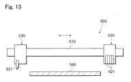
printer apparatus 500 is shown inFig. 13 as an example of a conventional printer apparatus which is structured to be capable of performing printing and a cutting work as described above. Theprinter apparatus 500 is structured so that aprinting unit 520 on which a plurality ofprinter heads 521 is mounted and acutting unit 530 on which acutter blade 531 is mounted are attached to aguide rail 510, which is provided so as to face aplaten 540 on which a printing medium (not shown) is placed and supported, so as to be movable in the right and left direction in the drawing. - When printing is to be performed on a printing medium, the
printing unit 520 is moved on with an upper side of theplaten 540 by a drive mechanism not shown and, on the other hand, when a cutting work is to be performed, thecutting unit 530 is moved on the upper side of theplaten 540. Further, in respective standby states of theprinting unit 520 and thecutting unit 530 which are not operated, they are separately located at right and left positions of theplaten 540 as shown inFig. 13 .
[Patent Literature 1] Japanese Patent Laid-Open No.2005-297248 - The document
US 2008/238996 A1 can be regarded as the closes prior-art document and discloses a printer comprising a guide rail which is extended in a scanning direction perpendicular to tne medium feeding direction, a first unit with a first working device (printhead) and a first carriage that is movable in the scanning direction along the rail, a second unit with a second carriage that is movable in the [0005] scanning direction along the rail, a first unit holding mechanism on a side in the scanning direction respect to the medium support means (platen), capable of holding the first unit. - Recently, in the printer apparatus in which printing and a cutting work are capable of performing as described above, the
printing unit 520 and thecutting unit 530 have been required to be in a standby state at only one of a right side position or a left side position of theplaten 540 from a standpoint of workability in maintenance or the like. In order to attain this requirement, inFig. 13 , for example, in a case that thecutting unit 530 is located on the side of theprinting unit 520 and two units are held in standby states on the right side end part of theguide rail 510 in the drawing, when theprinting unit 520 is to be moved to the upper side of theplaten 540 for printing, the operation is obstructed by thecutting unit 530. - In view of the problem described above, an objective of the present invention is to provide a printer apparatus which is capable of setting a plurality of units in standby states on one side of a platen to improve workability
- In order to solve the problem, the present invention provides a printer apparatus including;
- a guide rail which faces a medium support means (for example, the
platen 30 in the embodiment) supporting an object medium (for example, theprinting sheet 8 in the embodiment), is relatively moved in a predetermined feeding direction with respect to the object medium supported by the medium support means and is extended in a scanning direction perpendicular to the predetermined feeding direction, - a first mit which is provided with a first carriage that is movable in the scanning direction along the guide rail and a first working device which is mounted on the first carriage for performing a predetermined working on the object medium,
- a second unit which is provided with a second carriage that is movable in the scanning direction along the guide rail and a second working device which is mounted on the second carriage for performing a predetermined working on the object medium,
- a first unit holding mechanism (for example, the
second maintenance device 65 in the embodiment) which is provided on a side in the scanning direction with respect to the medium support means and is capable of holding the first unit, - a second unit holding mechanism (for example, the
left standby station 95L in the embodiment) which is provided between the medium support means and the first unit holding mechanism in the scanning direction and is capable of holding the second unit, and - a vertically retreat mechanism (for example, the vertically moving
mechanism 100 in the embodiment) which is structured so that the second unit held by the second unit holding mechanism and the second unit holding mechanism are capable of being moved together in an upper and lower direction with respect to the medium support means. - In this structure, when holding of the first unit by the first unit holding mechanism is to be released for performing a predetermined working while the first working device is moved in the scanning direction, the second unit and the second unit holding mechanism are moved to be located on a lower side with respect to the medium support means by the vertically retreat mechanism.
- In the printer apparatus described above, it is preferable that the first unit is a head unit (for example, the
second printing unit 60 in the embodiment) which is provided with a head carriage (for example, thecarriage 61 in the embodiment) that is movable in the scanning direction along the guide rail and a printer head that is mounted on the head carriage for ejecting ink to the object medium, and the second unit is a cutter unit (for example, thecutting unit 90 in the embodiment) which is provided with a cutter carriage (for example, thecarriage 91 in the embodiment) that is movable in the scanning direction along the guide rail and a cutter device (for example, thecutter holder 92 in the embodiment) that is mounted on the cutter carriage for performing a cutting work on the object medium in a predetermined shape. - Further, it is also preferable that the first unit is a cutter unit which is provided with a cutter carriage that is movable in the scanning direction along the guide rail and a cutter device that is mounted on the cutter carriage for performing a cutting work on the object medium in a predetermined shape, and the second unit is a head unit which is provided with a head carriage that is movable in the scanning direction along the guide rail and a printer head that is mounted on the head carriage and from which ink is ejected to the object medium.
- In addition, it may be also structured that each of the first unit and the second unit is a head unit which is provided with a head carriage that is movable in the scanning direction along the guide rail and a printer head that is mounted on the head carriage and from which ink is ejected to the object medium.
- It is preferable that the vertically retreat mechanism is provided with;
- a grooved shaft (for example, the
ball screw shaft 130 in the embodiment) whose outer peripheral face is formed with a spiral groove part and which is vertically extended and attached to the second unit holding mechanism, - a fitted rotation member (for example, the
ball screw gear 131 in the embodiment) whose inner peripheral face is formed with a spiral groove part capable of being fitted to the outer peripheral face of the grooved shaft and which is accommodated in an inside of a fixed support part (for example, thefixed support base 110 in the embodiment) provided on a lower side of the second unit holding mechanism in a rotatably supported state in a horizontal plane so that the inner peripheral face is fitted with the outer peripheral face of the grooved shaft for supporting the grooved shaft, and - a drive motor (for example, the vertically drive
motor 120 in the embodiment) which is capable of rotationally driving the fitted rotation member. - In this structure, a force is applied in an upper direction and a lower direction to the grooved shaft which is fitted to the fitted rotation member by means of that the drive motor is rotated to rotate the fitted rotation member so that the second unit holding mechanism and the second unit are vertically moved with respect to the fixed support part.
- It is also preferable that the vertically retreat mechanism is provided with;
- a vertically conveyance device which accommodates a grooved shaft whose outer peripheral face is formed with a spiral groove part so as to be vertically extended, which rotatably supports the grooved shaft, and which is attached to a fixed support part provided on a lower side of the second unit holding mechanism,
- a moving support member (for example, the vertically support
member 151 and thelateral support member 152 in the embodiment) which is attached to the second unit holding mechanism for supporting the second unit holding mechanism and, in which a fitted part that is formed with a spiral groove part capable of fitting to the outer peripheral face of the grooved shaft is fitted with the grooved shaft so as to be capable of being vertically moved with respect to the vertically conveyance device, and - a drive motor which is capable of rotationally driving the grooved shaft.
- In this structure, a force is applied in an upper direction and a lower direction to the moving support member which is fitted with the grooved shaft by means of that the drive motor is rotated to rotate the grooved shaft so that the second unit holding mechanism and the second unit are vertically moved with respect to the fixed support part.
- Further, it may be also structured that the vertically retreat mechanism is provided with a piston device (for example, the
air cylinder 220 in the embodiment) whose one end is attached to a fixed support part provided on a lower side of the second unit holding mechanism and whose other end is attached to the second unit holding mechanism, and the piston device is disposed so as to be capable of being extended and retreated in an upper and lower direction, and the second unit holding mechanism and the second unit are vertically moved with respect to the fixed support part by the piston device which is extended and retreated. - In addition, it is also preferable that the vertically retreat mechanism is provided with a pair of pulleys (for example, the
drive pulley 271 and the drivenpulley 272 in the embodiment) which are disposed at an upper position and a lower position, an endless conveyance belt (for example, the movingbelt 260 in the embodiment) which is stretched over the pair of the pulleys so as to be extended in an upper and lower direction and connected with the second unit holding mechanism, and a drive motor which is capable of rotationally driving one of the pair of the pulleys. In this structure, the endless conveyance belt which is stretched over the pair of the pulleys is moved in the upper and lower direction by the drive motor that is rotated so that the second unit holding mechanism and the second unit are vertically moved with respect to the pair of the pulleys. - The printer apparatus in accordance with the present invention is structured so that, when a predetermined working is to be performed while the first working device is moved in the scanning direction, the second unit and the second unit holding mechanism are moved to be located at a lower position with respect to the medium support means by the vertically retreat mechanism. According to this structure, even when the first unit and the second unit are set in standby states on the same side in the scanning direction with respect to the medium support means, since the second unit which is located nearer to the medium support means is retreated by the vertically retreat mechanism as needed, working to the object medium by the first unit is prevented from being obstructed by the second unit. Further, since a plurality of units are capable of being set in standby states on one side with respect to the platen, for example, an operator is capable of simultaneously performing maintenance or the like on the plurality of the units and thus workability can be improved.
- In the printer apparatus described above, it is preferable that the first unit is a head unit which is provided with a printer head for ejecting ink to an object medium and the second unit is a cutter unit which is provided with a cutter device for performing a cutting work on the object medium in a predetermined shape. According to this structure, when the cutter unit is vertically moved by the vertically retreat mechanism, since the number of wiring lines, piping lines and the like of the cutter unit is commonly smaller in comparison with that of the head unit, the structure of the device relating to wiring lines, piping lines and the like can be made simple.
- On the other hand, it is also preferable that the first unit is a cutter unit which is provided with a cutter device for performing a cutting work on an object medium in a predetermined shape and the second unit is a head unit which is provided with a printer head for ejecting ink to the object medium. According to this structure, for example, in a case that use frequency of the head unit is higher than that of the cutter unit, the number of times of the head unit which is vertically moved by the vertically retreat mechanism is reduced to shorten the working time and thus the working efficiency can be improved.
- In addition, it is also preferable that each of the first unit and the second unit is a head unit which is provided with a printer head for ejecting ink to an object medium. For example, when a printer head for ink which is hardly used at the time of normal printing is mounted on the first unit and printer heads for basic colors are mounted on the second unit, the vertical movement by the vertically retreat mechanism is not required at the time of normal printing with the use of the basic colors and thus the printing can be performed efficiently.
- Further, it is preferable that the vertically retreat mechanism is structured so that a drive motor is rotated to rotate a fitted rotation member which is fitted with a grooved shaft and a force is applied to the grooved shaft fitted with the fitted rotation member in an upper direction and a lower direction to vertically move the second unit with respect to the fixed support part. According to this structure, the second unit can be moved in the upper and lower direction with a high degree of accuracy by the drive motor whose driving and rotating are controlled and thus, for example, holding of the second unit by the second unit holding mechanism and retreating of the second unit by the second unit holding mechanism can be performed surely
- Further, it is also preferable that the vertically retreat mechanism is structured by using a vertically conveyance device which is provided with a rotatable grooved shaft and which is attached to a fixed support part, and the vertically retreat mechanism is structured so that a drive motor is rotated to rotate the grooved shaft and a force is applied to a moving support member supporting the second unit holding mechanism in an upper direction and a lower direction to vertically move the second unit with respect to the fixed support part. According to this structure, a vertically conveyance device which has been put on the market as an inexpensive general purpose product may be used and thus a manufacturing cost of the printer apparatus can be reduced as a whole.
- In addition, it is also preferable that the vertically retreat mechanism is structured by using the piston device which is disposed so as to be capable of being extended and retreated in an upper and lower direction. In this case, when the piston device is simply extended, the second unit can be held by the second unit holding mechanism and, when the piston device is simply retreated, the second unit can be retreated by the second unit holding mechanism and thus the device and operation for the vertically retreat mechanism can be structured to be simple.
- It is also desirable that the vertically retreat mechanism is structured so that a drive motor is rotated to vertically move an endless conveyance belt which is stretched over a pair of pulleys to vertically move the second unit. According to this structure, although the mechanism using the pulleys and the endless conveyance belt is simple and inexpensive, the second unit can be moved with a high degree of accuracy and, for example, the second unit is held by the second unit holding mechanism and the second unit is retreated by the second unit holding mechanism surely.
-
Fig. 1 is a perspective view showing an outward appearance of a printer apparatus in accordance with embodiments of the present invention (first through fourth embodiments). -
Fig. 2 is a front view showing a vicinity of a guide rail of the printer apparatus. -
Fig. 3 is a plan view showing a vicinity of the guide rail of the printer apparatus. -
Fig. 4 is a plan view showing a unit drive device of the printer apparatus. -
Figs. 5(a), 5(b) and 5(c) are cross-sectional views showing connecting states of a drive carriage with a connecting part.Fig. 5(a) shows a state before connected,Fig. 5(b) shows a state after connected, andFig. 5(c) shows a state where the connection has been released. -
Fig. 6 is a side view showing a vertically moving mechanism (upper side moved state) in accordance with a first embodiment. -
Fig. 7 is a side view showing the vertically moving mechanism (lower side moved state) in accordance with the first embodiment. -
Fig. 8 is a side view showing a vertically moving mechanism (upper side moved state) in accordance with a second embodiment. -
Fig. 9 is a side view showing the vertically moving mechanism (lower side moved state) in accordance with the second embodiment. -
Fig. 10 is a side view showing a vertically moving mechanism (upper side moved state) in accordance with a third embodiment. -
Fig. 11 is a side view showing the vertically moving mechanism (lower side moved state) in accordance with the third embodiment. -
Fig. 12 is a side view showing a vertically moving mechanism in accordance with a fourth embodiment. -
Fig. 13 is a front view showing a part of a conventional printer apparatus. -
- 8
- printing sheet (object medium)
- 30
- platen (medium support means)
- 40
- guide rail
- 60
- second printing unit (head unit)
- 61
- carriage (head carriage)
- 62
- printer head
- 65
- second maintenance device (first unit holding mechanism)
- 90
- cutting unit (cutter unit)
- 91
- carriage (cutter carriage)
- 92
- cutter holder (cutter device)
- 95L
- left standby station (second unit holding mechanism)
- 100
- vertically moving mechanism (vertically retreat mechanism)
- 110
- fixed support base (fixed support part)
- 120
- vertically drive motor (drive motor)
- 130
- ball screw shaft (grooved shaft)
- 131
- ball screw gear (fitted rotation member)
- 151
- vertically support member (moving support member)
- 152
- lateral support member (moving support member)
- 170
- vertically conveyance device
- 220
- air cylinder (piston device)
- 260
- moving belt (endless conveyance belt)
- 271
- drive pulley (pulley)
- 272
- driven pulley (pulleys)
- Preferred embodiments of the present invention will be described below on the basis of first through fourth embodiments with reference to the accompanying drawings. In the following description, in convenience of description, arrow directions shown in respective drawings are respectively defined as a front and rear direction, a right and left (lateral) direction and an upper and lower (vertical) direction.
- A structure of a
printer apparatus 1 in accordance with a first embodiment will be described below with reference toFigs. 1 through 7 .Fig. 1 is a perspective view showing aprinter apparatus 1,Figs. 2 and3 show a vicinity of aguide rail 40 described below,Fig. 4 is a plan view showing aunit drive device 80 described below,Figs. 5(a), 5(b) and 5(c) are cross-sectional views showing connecting portions of adrive carriage 85 with a connecting part 53 (connectingpart 63 and connecting part 93) described below, andFigs. 6 and7 show a verticallymovable mechanism 100 described below. - The
printer apparatus 1 is, as shown inFig. 1 , mainly structured of amain body part 3 which is extended in a right and left direction and asupport part 2 which is provided with a pair oflegs main body part 3. A leftmain body part 5 and a rightmain body part 6 are respectively formed at right and left end parts of themain body part 3 and their outer peripheral portions are covered with amain body cover 4. An inside of the leftmain body part 5 is provided with a controller (not shown) which outputs an operation signal to respective structure portions of theprinter apparatus 1 described below for controlling their operations. - A
feed mechanism 20, aplaten 30 which is formed in a flat plate shape for supporting aprinting sheet 8 which is an object to be printed, aguide rail 40 which is extended in the right and left direction on an upper side of theplaten 30, afirst printing unit 50 and asecond printing unit 60, aunit drive device 80, a cuttingunit 90 and the like are structured and disposed between the leftmain body part 5 and the rightmain body part 6. InFigs. 2 and3 , aright standby station 95R and aleft standby station 95L are provided on a right side and a left side of theplaten 30. However, for example, it may be structured that only theright standby station 95L is provided. - The
feed mechanism 20 is mainly structured of a plurality ofpinch rollers 22 which are rotatably disposed side by side in the right and left direction and afeed roller 21 which is provided on an under side of thepinch rollers 22 and on a rear side of theplaten 30. When thefeed roller 21 is rotated in a state that aprinting sheet 8 is sandwiched between thefeed roller 21 and thepinch rollers 22, theprinting sheet 8 is fed by a predetermined distance in the front direction and the rear direction. - The
first printing unit 50 is, as shown inFig. 2 , mainly structured of acarriage 51 which is attached to theguide rail 40 so as to be movable in the right and left direction and a plurality of printer heads 52 which are structured for basic colors such as magenta, yellow, cyan and black. A plate-shaped connectingpart 53 whose center portion is formed with a fitting recessedpart 53a is provided on the rear part of thecarriage 51 so as to extend to a rear side (seeFig. 3 ) and afitting projection 86 of adrive carriage 85 described below is arranged so as to be capable of fitting to the recessedpart 53a. The printer heads 52 are mounted on thecarriage 51 in a state that a plurality of ejection nozzles (not shown) from which ink is ejected is directed to the lower side. Theprinter head 52 is connected with an ink cartridge (not shown) which is mounted on theprinter apparatus 1 through atube 7 and ink in the ink cartridge is supplied through thetube 7. - The
second printing unit 60 is mainly structured of acarriage 61 which is attached to theguide rail 40 so as to be movable in the right and left direction and a plurality of printer heads 62 which are structured for white, metallic, pearl and fluorescent color which are difficult to be simultaneously printed with the basic colors (hereinafter, referred to as special colors to the basic colors). Similarly to thecarriage 51, a plate-shaped connectingpart 63 whose center portion is formed with a fitting recessedpart 63a is provided so as to extend to the rear side (seeFig. 3 ). The printer heads 62 are, similarly to the printer heads 52, mounted on thecarriage 61 in a state that a plurality of ejection nozzles (not shown) from which ink is ejected is directed to the lower side. However, different from theprinter head 52, the printer heads 52 are respectively structured so that a predetermined quantity of ink is capable of being stored in the inside of the head and mounted on thecarriage 61 in a detachable manner. - As shown in
Fig. 2 , afirst maintenance device 55 is provided on a lower side of theguide rail 40 in the rightmain body part 6 so as to face thefirst printing unit 50 in the upper and lower direction which has been moved to a first maintenance position on the right side of theplaten 30. Thefirst maintenance device 55 is structured so that suction caps 56 for covering under faces of the printer heads 52 (face where the ejection nozzle is formed) to prevent from being dried are attached on an upper face of astage 57 which is movable in the upper and lower direction. Further, the inside of thesuction cap 56 is set in a negative pressure in a state that the under face of theprinter head 52 is covered so that the ink within the ejection nozzle is sucked and discharged. - As described below, when the
first printing unit 50 is moved to the first maintenance position, thestage 57 is automatically moved upward and the under faces of the printer heads 52 are covered by the suction caps 56 to prevent the ejection nozzles from being dried. Further, in this case, the suction caps 56 are abutted with the under faces of the printer heads 52 and thus thefirst printing unit 50 is held at the first maintenance position. A left end part of thestage 57 is attached with awiper 58, which is made of flexible material such as rubber and capable of abutting with the under face of theprinter head 52 and movable in the front and rear direction. - A
second maintenance device 65 is provided on a lower side of theguide rail 40 in the leftmain body part 5 so as to face thesecond printing unit 60, which has been moved to a second maintenance position on the left side of theplaten 30, in the upper and lower direction. Thesecond maintenance device 65 is, similarly to thefirst maintenance device 55, attached with suction caps 66 and awiper 68 on an upper face side of thestage 67 and structured so as to perform similar operations to thefirst maintenance device 55. - The cutting
unit 90 is, as shown inFig. 2 , mainly structured of acarriage 91 which is movably attached to theguide rail 40 in the right and left direction and acutter holder 92 which is mounted on thecarriage 91. Similarly to thecarriage 51, a plate-shaped connectingpart 93 whose center portion is formed with a fitting recessedpart 93a is provided on the rear side of thecarriage 91 so as to extend to the rear side (seeFig. 3 ). Acutter blade 92a is detachably mounted on a lower end part of thecutter holder 92 and movably mounted on thecarriage 91 in an upper and lower direction. - The
unit drive device 80 is, as shown inFig. 2 , manly structured of adrive pulley 81 and a drivenpulley 82, which are provided at the right and left end parts of theguide rail 40, a right and leftdrive motor 83 for rotatably driving thedrive pulley 81, a band-shapedtoothed drive belt 84 which is stretched over thepulleys drive carriage 85 which is connected with thetoothed drive belt 84. - The
drive carriage 85 is, as shown inFigs. 5(a), 5(b) and 5(c) , mainly structured of amain body part 89, afitting projection 86 which is inserted into themain body part 89 so as to be movable in the front and rear direction, an urgingspring 87 which urges thefitting projection 86 to a front side with respect to themain body part 89, and anelectromagnet 88 which is attached to themain body part 89. A front andrear stopper 86a is attached to a rear end part of thefitting projection 86. Theelectromagnet 88 is provided so that generation of its magnetic force is controlled on the basis of an operation signal from the controller. - In this structure, the rotational driving of the right and left
drive motor 83 and the magnetic force generation of theelectromagnet 88 are controlled by the controller and, in this manner, thefirst printing unit 50, thesecond printing unit 60 and the cuttingunit 90 are controlled so as to move in the right and left direction along theguide rail 40. - The
left standby station 95L is provided on a lower side of theguide rail 40 in the leftmain body part 5 and faces the cuttingunit 90 which has been moved to a left standby position on the left side with respect to the platen 30 (left side with respect to theplaten 30 and right side with respect to the second maintenance device 65). Further, as shown inFigs. 6 and7 , theleft standby station 95L is provided with a vertically movingmechanism 100 for moving theleft standby station 95L in an upper and lower direction. - ... In a state that the cutting
unit 90 has been moved to the left standby position, when theleft standby station 95L is moved upward by the vertically movingmechanism 100, theleft standby station 95L is abutted with an under face of the cuttingunit 90 to hold thecutting unit 90 at the left standby position. Theright standby station 95R is structured similarly to theleft standby station 95L and provided at a right standby position on the right side with respect to the platen 30 (right side with respect to theplaten 30 and left side with respect to the first maintenance device 65). - As shown in
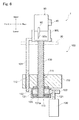
Fig. 6 , the vertically movingmechanism 100 is mainly structured of aguide member 101 which is connected with theleft standby station 95L and extended in an upper and lower direction, a fixedsupport base 110 which is fixed to a frame member, for example, theleg 2a of theprinter apparatus 1, a vertically drivemotor 120, and aball screw shaft 130. The fixedsupport base 110 is structured by using, for example, a flat plate-shaped member and formed with a ballscrew shaft hole 111 and aguide hole 112 which are penetrated vertically and agear housing chamber 113 which is protruded toward lower side from its under face. - A
ball screw gear 131 is accommodated in thegear housing chamber 113 in a state that theball screw gear 131 is sandwiched by anupper bearing 132 and alower bearing 133 in the upper and lower direction. A plurality ofballs 131a is rotatably provided on a female screw part (not shown) which is formed on an inner peripheral face of theball screw gear 131 and an outer gear (not shown) is formed on an outer peripheral face of theball screw gear 131 to be rotatable in a horizontal plane. - The
ball screw shaft 130 is a screw shaft which is formed with a male screw part (not shown) on its outer peripheral face and extended in the upper and lower direction and its upper end part is attached to an under face of theleft standby station 95L. Further, theball screw shaft 130 is inserted into the ball screwshaft hole 111 so as to be capable of moving vertically (upper and lower direction) and the outer peripheral face (male screw part) of theball screw shaft 130 is fitted with the inner peripheral face (female screw part) of theball screw gear 131 in thegear housing chamber 113. The vertically drivemotor 120 is controlled so as to be driven and rotated by the controller to rotatably drive theball screw gear 131 through adrive gear 122 which is attached to anoutput shaft 121. Theguide member 101 is inserted into theguide hole 112 of the fixedsupport base 110 so as to be capable of moving in a vertical direction. - The structure of the
printer apparatus 1 has been described above and next, an operation of the respective structural members at the time of printing will be described below. - In the following description, an operation will be described as an example in which, first, printing is performed on a
printing sheet 8 by using the basic colors and then, printing using special colors is performed on theprinting sheet 8 where printing has been performed by using the basic colors and then, finally, theprinting sheet 8 is cut in a desired shape. Before printing is started (standby state), in this example, thedrive carriage 85 is not connected with any unit as shown inFig. 2 . Further, thefirst printing unit 50 is held at the first maintenance position by thefirst maintenance device 55, thesecond printing unit 60 is held at the second maintenance position by thesecond maintenance device 65, and the cuttingunit 90 is held at the left standby position by theleft standby station 95L respectively. - When printing is started by an operator who operates the
printer apparatus 1, thedrive carriage 85 is moved in the right direction to the first maintenance position and thedrive carriage 85 and thefirst printing unit 50 are connected with each other and thefirst maintenance device 55 is moved down. Next, on an upper side of aprinting sheet 8 which is placed on theplaten 30, an operation where inks are ejected from the printer heads 52 while thefirst printing unit 50 is moved in the right and left direction in a reciprocated manner and an operation feeding theprinting sheet 8 to the front side are performed in a combined manner and, as a result, printing with the use of the basic colors is performed on theprinting sheet 8. - When the printing with the use of the basic colors has been finished, the
first printing mit 50 is moved to the first maintenance position and held by thefirst maintenance device 55. Next, thedrive carriage 85 is to be connected with thesecond printing unit 60 for performing printing with the use of the special colors. However, in this case, since the cuttingunit 90 is obstructively located on the right side of thesecond printing unit 60, thesecond printing unit 60 is unable to be moved on an upper side of theprinting sheet 8 due to the cuttingunit 90. Therefore, the cuttingunit 90 and theleft standby station 95L are moved down together by the vertically movingmechanism 100, by which theleft standby station 95L has been moved upward to hold thecutting unit 90 at the left standby position, to retreat from the position so that thesecond printing unit 60 can be moved on an upper side of theprinting sheet 8. - More specifically, the vertically drive
motor 120 is driven and rotated to rotate theball screw gear 131 in the horizontal plane through theoutput shaft 121 and thedrive gear 122. In this manner, a downward force is applied to theball screw shaft 130 which is engaged with the inner peripheral face of theball screw gear 131 to move theball screw shaft 130 downward with respect to the fixed support base 110 (ball screw gear 131). In this case, since theguide member 101 is moved downward while being guided by theguide hole 112, the cuttingunit 90 and theleft standby station 95L are straightly moved down without being rotated with the rotation of theball screw gear 131. As shown inFig. 7 , when the cuttingunit 90 is moved down to an under side position of theplaten 30, the driving of the vertically drivemotor 120 is stopped. - In the state shown in
Fig. 7 , thesecond printing unit 60 connected with thedrive carriage 85 is capable of being passed on the upper side of the cuttingunit 90 to be moved to an upper side of theprinting sheet 8 and printing with the use of the special colors can be performed. When printing with the use of the special colors has been finished, thesecond printing unit 60 is passed on the upper side of the cuttingunit 90 to be moved to the second maintenance position and held by thesecond maintenance device 65. - After that, the vertically drive
motor 120 of the vertically movingmechanism 100 is driven and rotated in the opposite direction to the above-mentioned operation and the cuttingunit 90 and theleft standby station 95L are moved upward together and thecarriage 91 is fitted to the guide rail 40 (seeFig. 6 ). After that, the cuttingunit 90 which is in a movable state along theguide rail 40 is connected with thedrive carriage 85 and then, theleft standby station 95L is moved down, for example, to the lower side of theplaten 30 by the vertically movingmechanism 100 to release the cuttingunit 90 which has been held by theleft standby station 95L. - As a result, the cutting
unit 90 can be moved on an upper side of theprinting sheet 8 to cut theprinting sheet 8 in a desired shape. When the cutting work has been finished, the cuttingunit 90 is moved to the left standby position and held by theleft standby station 95L which is moved upward by the vertically movingmechanism 100 and a series of printings and a cutting work to theprinting sheet 8 has finished. - As described above, in the
printer apparatus 1 in accordance with the present invention, the cuttingunit 90 set in a standby state on theplaten 30 side can be retreated and located on the lower side of theplaten 30 by the vertically movingmechanism 100 as needed. Therefore, even when two units, i.e., thesecond printing unit 60 and the cuttingunit 90 are structured so as to be in standby states on the left side of theplaten 30, thesecond printing unit 60 can be moved on the upper side of theprinting sheet 8 to perform printing. - In addition, for example, in a case that two units, i.e., the
first printing unit 50 and the cuttingunit 90 are mounted on theguide rail 40, these two units are set in standby states on the left side of theplaten 30. In this case, an operator is capable of immediately performing an operation on theprinter apparatus 1 and maintenance or the like to the first printing unit 50 (cutting unit 90) without changing his or her position and thus workability can be improved. - Next, a vertically moving
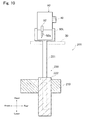
mechanism 150 will be described below with reference toFigs. 8 and9 as another embodiment of the vertically movingmechanism 100 in theprinter apparatus 1 in accordance with the first embodiment. The same reference numbers are used for the members described in the first embodiment and their descriptions are omitted.Fig. 8 shows a state that the cuttingunit 90 is held by theleft standby station 95L andFig. 9 shows a state that the cuttingunit 90 has been moved down and retreated respectively. - The vertically moving
mechanism 150 is, as shown inFig. 8 , mainly structured of a verticallysupport member 151 which is connected with theleft standby station 95L and extended in a lower direction, alateral support member 152 which is connected with a lower part of the verticallysupport member 151 and extended in a lateral direction, a fixedsupport base 160 which is fixed to a frame member of theprinter apparatus 1 such as theleg 2a, a vertically drivemotor 120 and a verticallyconveyance device 170. The vertically conveyancedevice 170 is structured so that, for example, a ballspiral shaft 190 whose outer peripheral face is formed with a spiral groove in the upper and lower direction is accommodated in the inside of ahousing frame 180. An upper end part of the ballspiral shaft 190 is supported by anupper bearing 192 and its lower end part is supported by alower bearing 193 and thus the ballspiral shaft 190 is rotatably supported. Further, a lower part of the ballspiral shaft 190 is protruded from thehousing frame 180 to the lower side and the protruded portion is attached with a drivengear 191 whose outer peripheral face is formed with an outer gear (not shown). In accordance with an embodiment, a device which has been put on the market as a general purpose product may be used as the verticallyconveyance device 170. - The fixed
support base 160 is, for example, structured by using a flat plate-shaped member and the verticallyconveyance device 170 is fixed to the fixedsupport base 160. The front part of thelateral support member 152 is inserted into thehousing frame 180 in a vertically movable manner and aninsertion hole 153 which is penetrated in the upper and lower direction is formed in a front end part of thelateral support member 152. A plurality ofballs 153a is rotatably provided on an inner peripheral face of theinsertion hole 153 and the ballspiral shaft 190 is inserted into theinsertion hole 153 and theballs 153a are fitted with the spiral groove of the ballspiral shaft 190. - The structure of the vertically moving
mechanism 150 has been described as described above. Next, an operation will be described below in which, in a state that theleft standby station 95L is moved upward and the cuttingunit 90 is held at the left standby position as shown inFig. 8 , the cuttingunit 90 and theleft standby station 95L are retreated so that thesecond printing unit 60 can be moved to an upper side of aprinting sheet 8. - In the state shown in
Fig. 8 , the vertically drivemotor 120 is driven and rotated to rotate the drivengear 191 and the ballspiral shaft 190 through theoutput shaft 121 and thedrive gear 122. As a result, a downward force is applied to thelateral support member 152 which is engaged with the ballspiral shaft 190 and thelateral support member 152 is moved downward with respect to the fixed support base 160 (ball spiral shaft 190). Therefore, the verticallysupport member 151 connected with thelateral support member 152, theleft standby station 95L and the cuttingunit 90 are moved down together until the cuttingunit 90 is located on a lower side of theplaten 30. When the cuttingunit 90 is moved down until the cuttingunit 90 is located on the lower side of theplaten 30 as shown inFig. 9 , the driving of the vertically drivemotor 120 is stopped. In this manner, the cuttingunit 90 and theleft standby station 95L are retreated. - According to the structure of the
printer apparatus 1 with the use of the vertically movingmechanism 150 as described above, in addition to the effects of the first embodiment, since the verticallyconveyance device 170 is structured by using a device which has been generally put on the market, the manufacturing cost of theprinter apparatus 1 can be reduced in total. - Next, a vertically moving
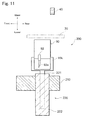
mechanism 200 will be described below with reference toFigs. 10 and11 as another embodiment of the vertically movingmechanism 100 in theprinter apparatus 1 in accordance with the first embodiment. The same reference numbers are used for the members described in the first embodiment and their descriptions are omitted.Fig. 10 shows a state that the cuttingunit 90 is held by theleft standby station 95L andFig. 11 shows a state that the cuttingunit 90 has been moved down and retreated respectively. - The vertically moving
mechanism 200 is, as shown inFig. 10 , structured by using anair cylinder 220 and an upper end part of acylinder rod 221 is attached to theleft standby station 95L and a cylindermain body 222 is fixed to a fixedsupport base 210. In a state that theleft standby station 95L is moved upward by the vertically movingmechanism 200 to hold the cutting unit 90 (seeFig. 10 ), when the cuttingunit 90 is to be retreated in the lower direction, thecylinder rod 221 extended to an upper side is pulled down and the cuttingunit 90 is located on an under side of theplaten 30. In this manner, the cuttingunit 90 and theleft standby station 95L are retreated. - According to the structure of the
printer apparatus 1 with the use of the vertically movingmechanism 200 as described above, in addition to the effects of the first embodiment, since the number of the structure members of the vertically moving mechanism is reduced, the manufacturing cost of theprinter apparatus 1 can be reduced in total. - Next, a vertically moving
mechanism 250 will be described below with reference toFig. 12 as another embodiment of the vertically movingmechanism 100 in theprinter apparatus 1 in accordance with the first embodiment. The same reference numbers are used for the members described in the first embodiment and their descriptions are omitted. InFig. 12 , a state where the cuttingunit 90 is held by theleft standby station 95L is shown by the solid line and a state where the cuttingunit 90 has been moved down and retreated is shown by the dotted line respectively. - The vertically moving
mechanism 250 is, as shown inFig. 12 , mainly structured of a vertically drivemotor 120, adrive pulley 271 connected with the vertically drivemotor 120, a drivenpulley 272 which is disposed on an upper side of thedrive pulley 271 so as to be paired with thedrive pulley 271, and a movingbelt 260 which is stretched over thedrive pulley 271 and the drivenpulley 272. The movingbelt 260 is attached to aconnection part 251 which is formed at a rear part of theleft standby station 95L. - According to this structure, in the state shown by the solid line in
Fig. 12 , when the cuttingunit 90 is to be moved down and retreated, the vertically drivemotor 120 is driven and rotated to move down theleft standby station 95L and the cuttingunit 90 through the movingbelt 260. - According to the structure of the
printer apparatus 1 with the use of the vertically movingmechanism 250 as described above, in addition to the effects of the first embodiment, although the mechanism is structured by using simple and inexpensive structure members (drivepulley 271, drivenpulley 272 and movingbelt 260 and the like), a vertical position of theleft standby station 95L is controlled with a high degree of accuracy. - In the embodiments described above, the structures in which the
cutting unit 90 is moved down and retreated are described as an example. However, the present invention is not limited to this structure. For example, one of the vertically moving mechanisms described above may be attached to thefirst maintenance device 55 to make thefirst printing unit 50 move down and retreat, or one of the vertically moving mechanisms described above may be attached to thesecond maintenance device 65 to make thesecond printing unit 60 retreat. - In the embodiments described above, as shown in
Fig. 2 , thefirst maintenance device 55 and theright standby station 95R are arranged on the right side with respect to theplaten 30 and thesecond maintenance device 65 and theleft standby station 95L are arranged on the left side with respect to theplaten 30, but the present invention is not limited to this structure. The printing mit and the cutting unit (maintenance device and standby station) may be arbitrarily arranged on either side with respect to theplaten 30. Further, for example, when a maintenance device and a standby station are disposed on one of the right and left sides with respect to theplaten 30, one of the vertically moving mechanisms described above may be attached to the maintenance device or the standby station which is disposed on the side of theplaten 30. - In the embodiment described above, the present invention is applied to a printer apparatus in one axis printing sheet moving type and one axis printing unit moving type but the present invention is not limited to this structure. The present invention may be applied to another type of a printer apparatus, for example, a printer apparatus in two axes printing unit moving type (flat bed type) or in two axes printing sheet moving type. Further, the inks which are used are not limited to a dye-based ink or a pigment-based ink and the present invention may be applied to a printer apparatus in which, for example, an ultraviolet curing type ink is used.
Claims (8)
- A printer apparatus (1) comprising:a guide rail (40) which faces a medium support means (30) for supporting an object medium (8), is relatively movable in a predetermined feeding direction with respect to the object medium when it is supported by the medium support means, (30) and is extended in a scanning direction perpendicular to the predetermined feeding direction;a first unit (50) which is provided with a first carriage (85) that is movable in the scanning direction along the guide rail (40) and a first working device (50) which is mounted on the first carriage (85) for performing a predetermined work on the object medium (8);a second unit (60) which is provided with a second carriage (61) that is movable in the scanning direction along the guide rail (40) and a second working device (62) which is mounted on the second carriage (61) for performing a predetermined work on the object medium;a first unit holding mechanism which is provided on a side in the scanning direction with respect to the medium support means (30) and is capable of holding the first unit (50);a second unit holding mechanism which is provided between the medium support means (30) and the first unit holding mechanism in the scanning direction and is capable of holding the second unit (60); anda vertically retreat mechanism (100) which is structured so that the second unit (60) held by the second unit holding mechanism and the second unit holding mechanism are capable of being moved together in an upper and lower direction with respect to the medium support means (30);wherein when holding of the first unit (50) by the first unit holding mechanism is to be released for performing a predetermined work while the first working device is moved in the scanning direction, the second unit (60) and the second unit holding mechanism are moved by the vertically retreat mechanism (100) to be located on a lower side with respect to the medium support means (30).
- The printer apparatus according to claim 1, wherein
the first unit is a head unit which is provided with a head carriage that is movable in the scanning direction along the guide rail and a printer head that is mounted on the head carriage and from which ink is ejected to the object medium, and
the second unit is a cutter unit which is provided with a cutter carriage that is movable in the scanning direction along the guide rail and a cutter device that is mounted on the cutter carriage for performing a cutting work on the object medium in a predetermined shape. - The printer apparatus according to claim 1, wherein
the first unit is a cutter unit which is provided with a cutter carriage that is movable in the scanning direction along the guide rail and a cutter device that is mounted on the cutter carriage for performing a cutting work on the object medium in a predetermined shape, and
the second unit is a head unit which is provided with a head carriage that is movable in the scanning direction along the guide rail and a printer head that is mounted on the head carriage and from which ink is ejected to the object medium. - The printer apparatus according to claim 1, wherein each of the first unit and the second unit is a head unit which is provided with a head carriage that is movable in the scanning direction along the guide rail and a printer head that is mounted on the head carriage and from which ink is ejected to the object medium.
- The printer apparatus according to one of claims 1 through 4, wherein
the vertically retreat mechanism is provided with;a grooved shaft whose outer peripheral face is formed with a spiral groove part and which is vertically extended and attached to the second unit holding mechanism,a fitted rotation member whose inner peripheral face is formed with a spiral groove part capable of being fitted to the outer peripheral face of the grooved shaft and which is accommodated in an inside of a fixed support part provided on a lower side of the second unit holding mechanism in a rotatably supported state in a horizontal plane so that the inner peripheral face is fitted with the outer peripheral face of the grooved shaft for supporting the grooved shaft, anda drive motor which is capable of rotationally driving the fitted rotation member, anda force is applied in an upper direction and a lower direction to the grooved shaft which is fitted to the fitted rotation member by means of that the drive motor is rotated to rotate the fitted rotation member so that the second unit holding mechanism and the second unit are vertically moved with respect to the fixed support part. - The printer apparatus according to one of claims 1 through 4, wherein the vertically retreat mechanism is provided with;a vertically conveyance device which accommodates a grooved shaft whose outer peripheral face is formed with a spiral groove part so as to be vertically extended, which rotatably supports the grooved shaft, and which is attached to a fixed support part provided on a lower side of the second unit holding mechanism,a moving support member which is attached to the second unit holding mechanism for supporting the second unit holding mechanism and, in which a fitted part that is formed with a spiral groove part capable of fitting to the outer peripheral face of the grooved shaft is fitted with the grooved shaft so as to be capable of being vertically moved with respect to the vertically conveyance device, anda drive motor which is capable of rotationally driving the grooved shaft, anda force is applied in an upper direction and a lower direction to the moving support member which is fitted with the grooved shaft by means of that the drive motor is rotated to rotate the grooved shaft so that the second unit holding mechanism and the second unit are vertically moved with respect to the fixed support part.
- The printer apparatus according to one of claims 1 through 4, wherein
the vertically retreat mechanism is provided with a piston device whose one end is attached to a fixed support part provided on a lower side of the second unit holding mechanism and whose other end is attached to the second unit holding mechanism, the piston device being disposed so as to be capable of being extended and retreated in an upper and lower direction, and
the second unit holding mechanism and the second unit are vertically moved with respect to the fixed support part by the piston device which is extended and retreated. - The printer apparatus according to one of claims 1 through 4, wherein
the vertically retreat mechanism is provided with;a pair of pulleys which are disposed at an upper position and a lower position,an endless conveyance belt which is stretched over the pair of the pulleys so as to be extended in an upper and lower direction and connected with the second unit holding mechanism, anda drive motor which is capable of rotationally driving one of the pair of the pulley, andthe endless conveyance belt stretched over the pair of the pulleys is moved in the upper and lower direction by the drive motor which is rotated so that the second unit holding mechanism and the second unit are vertically moved with respect to the pair of the pulleys.
Applications Claiming Priority (1)
| Application Number | Priority Date | Filing Date | Title |
|---|---|---|---|
| PCT/JP2008/073586 WO2010073338A1 (en) | 2008-12-25 | 2008-12-25 | Printer device |
Publications (3)
| Publication Number | Publication Date |
|---|---|
| EP2371560A4 EP2371560A4 (en) | 2011-10-05 |
| EP2371560A1 EP2371560A1 (en) | 2011-10-05 |
| EP2371560B1 true EP2371560B1 (en) | 2012-05-16 |
Family
ID=42287006
Family Applications (1)
| Application Number | Title | Priority Date | Filing Date |
|---|---|---|---|
| EP08879134A Not-in-force EP2371560B1 (en) | 2008-12-25 | 2008-12-25 | Printer device |
Country Status (6)
| Country | Link |
|---|---|
| US (1) | US8192097B2 (en) |
| EP (1) | EP2371560B1 (en) |
| JP (1) | JP5143915B2 (en) |
| KR (1) | KR101239860B1 (en) |
| CN (1) | CN102066117B (en) |
| WO (1) | WO2010073338A1 (en) |
Families Citing this family (11)
| Publication number | Priority date | Publication date | Assignee | Title |
|---|---|---|---|---|
| JP5760694B2 (en) * | 2011-05-26 | 2015-08-12 | セイコーエプソン株式会社 | Liquid ejection device |
| JP5854198B2 (en) * | 2011-09-09 | 2016-02-09 | 株式会社リコー | Image forming apparatus and recording medium |
| JP5862182B2 (en) * | 2011-10-12 | 2016-02-16 | 株式会社リコー | Image forming apparatus |
| CN105224975B (en) * | 2015-08-28 | 2018-07-20 | 河北汇金机电股份有限公司 | A kind of paper currency sorting assembly line and paper currency management method |
| JP7056100B2 (en) | 2017-11-29 | 2022-04-19 | セイコーエプソン株式会社 | Carriage movement mechanism and liquid discharge device |
| JP7277078B2 (en) * | 2018-03-29 | 2023-05-18 | キヤノン株式会社 | Inkjet recording device |
| CN108927995A (en) * | 2018-04-27 | 2018-12-04 | 合肥海闻自动化设备有限公司 | A kind of platform mechanism for sleeve Portable industrial figure punch |
| KR101985413B1 (en) | 2018-06-14 | 2019-06-03 | 에이에스티엔지니어링(주) | Vertical multi baking chamber apparatus |
| KR102083031B1 (en) | 2019-03-25 | 2020-04-23 | 김용태 | Vapor chamber laminating method and structure therefor |
| CN114590037A (en) * | 2022-03-11 | 2022-06-07 | 洛阳环升建筑科技有限公司 | Remove and spout a yard device |
| CN116118365B (en) * | 2023-02-03 | 2024-01-26 | 北京中程志远科技有限公司 | Printer capable of promoting ink drying |
Family Cites Families (15)
| Publication number | Priority date | Publication date | Assignee | Title |
|---|---|---|---|---|
| JP3333312B2 (en) * | 1994-03-24 | 2002-10-15 | ローランドディー.ジー.株式会社 | Image creation and cropping equipment |
| JP2773725B2 (en) * | 1996-01-09 | 1998-07-09 | 日本電気株式会社 | Serial recording device |
| JPH09240097A (en) * | 1996-03-08 | 1997-09-16 | Canon Inc | Equipment with scanning type carrier and printer |
| JP3245359B2 (en) * | 1996-07-30 | 2002-01-15 | キヤノン株式会社 | Image recording device |
| JPH1071710A (en) * | 1996-08-30 | 1998-03-17 | Oki Data:Kk | Ink jet printer |
| JPH1076729A (en) * | 1996-09-03 | 1998-03-24 | Shinko Seisakusho Co Ltd | Printer |
| JP2000218884A (en) * | 1999-02-02 | 2000-08-08 | Canon Inc | Recording apparatus |
| JP2005297248A (en) | 2004-04-07 | 2005-10-27 | Roland Dg Corp | Image forming and cutting apparatus |
| JP4241639B2 (en) * | 2005-02-14 | 2009-03-18 | セイコーエプソン株式会社 | Droplet discharge device and maintenance method of droplet discharge head |
| JP2006341420A (en) * | 2005-06-08 | 2006-12-21 | Roland Dg Corp | Image forming and clipping device |
| JP2007030253A (en) * | 2005-07-25 | 2007-02-08 | Canon Inc | Inkjet recording apparatus |
| US8529185B2 (en) * | 2005-08-31 | 2013-09-10 | Hirata Corporation | Work handling apparatus |
| JP4529929B2 (en) * | 2006-03-27 | 2010-08-25 | ブラザー工業株式会社 | Inkjet recording device |
| JP4909785B2 (en) * | 2007-03-28 | 2012-04-04 | 株式会社ミマキエンジニアリング | Printer / plotter device |
| JP4990001B2 (en) * | 2007-03-30 | 2012-08-01 | 株式会社ミマキエンジニアリング | Printer / plotter device |
-
2008
- 2008-12-25 KR KR1020107027482A patent/KR101239860B1/en not_active IP Right Cessation
- 2008-12-25 CN CN200880129859.5A patent/CN102066117B/en not_active Expired - Fee Related
- 2008-12-25 JP JP2010543676A patent/JP5143915B2/en active Active
- 2008-12-25 EP EP08879134A patent/EP2371560B1/en not_active Not-in-force
- 2008-12-25 WO PCT/JP2008/073586 patent/WO2010073338A1/en active Application Filing
-
2010
- 2010-11-30 US US12/955,934 patent/US8192097B2/en active Active
Also Published As
| Publication number | Publication date |
|---|---|
| KR101239860B1 (en) | 2013-03-06 |
| JPWO2010073338A1 (en) | 2012-05-31 |
| WO2010073338A1 (en) | 2010-07-01 |
| JP5143915B2 (en) | 2013-02-13 |
| CN102066117A (en) | 2011-05-18 |
| US8192097B2 (en) | 2012-06-05 |
| KR20110015612A (en) | 2011-02-16 |
| EP2371560A4 (en) | 2011-10-05 |
| CN102066117B (en) | 2014-04-30 |
| EP2371560A1 (en) | 2011-10-05 |
| US20110103870A1 (en) | 2011-05-05 |
Similar Documents
| Publication | Publication Date | Title |
|---|---|---|
| EP2371560B1 (en) | Printer device | |
| US7948650B2 (en) | Printer-plotter | |
| US8721067B2 (en) | Printer apparatus | |
| US8272733B2 (en) | Printer apparatus | |
| JP7000288B2 (en) | Inkjet printers and inkjet printers with cutting heads | |
| US8348414B2 (en) | Ink jet recording apparatus equipped with cutting head and ultraviolet light irradiation device | |
| US8262214B2 (en) | Ink jet printer | |
| US8267508B2 (en) | Ink jet printer | |
| US8277038B2 (en) | Ink jet printer | |
| US8794740B2 (en) | Ink jet recording apparatus | |
| JPH1158877A (en) | Dot matrix printer and manufacture thereof | |
| JP2001162872A (en) | Printing method, ink jet printer, and tape cartridge used for the printer | |
| JP4803310B2 (en) | Printing device | |
| JP2001163512A (en) | Ink jet printer | |
| JP5850198B2 (en) | Inkjet head unit and printing apparatus | |
| JP2005014095A (en) | Medium cutting device and recording device | |
| JP2011201324A (en) | Inkjet head unit, printing apparatus, printing method, and method of producing printed matter | |
| JP2005028700A (en) | Recording medium cutting device and recording apparatus | |
| JPH03146357A (en) | Printer | |
| JP2001162883A (en) | Ink jet printer | |
| JP2006103245A (en) | Inkjet recording device and its control method | |
| JP2000272147A (en) | Maintenance mechanism for ink jet head | |
| JP2005028701A (en) | Recording medium cutting device and recording apparatus |
Legal Events
| Date | Code | Title | Description |
|---|---|---|---|
| PUAI | Public reference made under article 153(3) epc to a published international application that has entered the european phase |
Free format text: ORIGINAL CODE: 0009012 |
|
| 17P | Request for examination filed |
Effective date: 20101117 |
|
| A4 | Supplementary search report drawn up and despatched |
Effective date: 20110318 |
|
| AK | Designated contracting states |
Kind code of ref document: A1 Designated state(s): AT BE BG CH CY CZ DE DK EE ES FI FR GB GR HR HU IE IS IT LI LT LU LV MC MT NL NO PL PT RO SE SI SK TR |
|
| GRAP | Despatch of communication of intention to grant a patent |
Free format text: ORIGINAL CODE: EPIDOSNIGR1 |
|
| RIC1 | Information provided on ipc code assigned before grant |
Ipc: B41J 3/54 20060101AFI20111125BHEP Ipc: B41J 11/70 20060101ALI20111125BHEP |
|
| GRAS | Grant fee paid |
Free format text: ORIGINAL CODE: EPIDOSNIGR3 |
|
| DAX | Request for extension of the european patent (deleted) | ||
| GRAA | (expected) grant |
Free format text: ORIGINAL CODE: 0009210 |
|
| RAP1 | Party data changed (applicant data changed or rights of an application transferred) |
Owner name: MIMAKI ENGINEERING CO., LTD. |
|
| AK | Designated contracting states |
Kind code of ref document: B1 Designated state(s): AT BE BG CH CY CZ DE DK EE ES FI FR GB GR HR HU IE IS IT LI LT LU LV MC MT NL NO PL PT RO SE SI SK TR |
|
| REG | Reference to a national code |
Ref country code: GB Ref legal event code: FG4D |
|
| REG | Reference to a national code |
Ref country code: CH Ref legal event code: EP |
|
| REG | Reference to a national code |
Ref country code: AT Ref legal event code: REF Ref document number: 557894 Country of ref document: AT Kind code of ref document: T Effective date: 20120615 |
|
| REG | Reference to a national code |
Ref country code: IE Ref legal event code: FG4D |
|
| REG | Reference to a national code |
Ref country code: DE Ref legal event code: R096 Ref document number: 602008015768 Country of ref document: DE Effective date: 20120712 |
|
| REG | Reference to a national code |
Ref country code: NL Ref legal event code: VDEP Effective date: 20120516 |
|
| REG | Reference to a national code |
Ref country code: LT Ref legal event code: MG4D Effective date: 20120516 |
|
| PG25 | Lapsed in a contracting state [announced via postgrant information from national office to epo] |
Ref country code: SE Free format text: LAPSE BECAUSE OF FAILURE TO SUBMIT A TRANSLATION OF THE DESCRIPTION OR TO PAY THE FEE WITHIN THE PRESCRIBED TIME-LIMIT Effective date: 20120516 Ref country code: NO Free format text: LAPSE BECAUSE OF FAILURE TO SUBMIT A TRANSLATION OF THE DESCRIPTION OR TO PAY THE FEE WITHIN THE PRESCRIBED TIME-LIMIT Effective date: 20120816 Ref country code: CY Free format text: LAPSE BECAUSE OF FAILURE TO SUBMIT A TRANSLATION OF THE DESCRIPTION OR TO PAY THE FEE WITHIN THE PRESCRIBED TIME-LIMIT Effective date: 20120516 Ref country code: PL Free format text: LAPSE BECAUSE OF FAILURE TO SUBMIT A TRANSLATION OF THE DESCRIPTION OR TO PAY THE FEE WITHIN THE PRESCRIBED TIME-LIMIT Effective date: 20120516 Ref country code: LT Free format text: LAPSE BECAUSE OF FAILURE TO SUBMIT A TRANSLATION OF THE DESCRIPTION OR TO PAY THE FEE WITHIN THE PRESCRIBED TIME-LIMIT Effective date: 20120516 Ref country code: IS Free format text: LAPSE BECAUSE OF FAILURE TO SUBMIT A TRANSLATION OF THE DESCRIPTION OR TO PAY THE FEE WITHIN THE PRESCRIBED TIME-LIMIT Effective date: 20120916 Ref country code: FI Free format text: LAPSE BECAUSE OF FAILURE TO SUBMIT A TRANSLATION OF THE DESCRIPTION OR TO PAY THE FEE WITHIN THE PRESCRIBED TIME-LIMIT Effective date: 20120516 |
|
| REG | Reference to a national code |
Ref country code: AT Ref legal event code: MK05 Ref document number: 557894 Country of ref document: AT Kind code of ref document: T Effective date: 20120516 |
|
| PG25 | Lapsed in a contracting state [announced via postgrant information from national office to epo] |
Ref country code: PT Free format text: LAPSE BECAUSE OF FAILURE TO SUBMIT A TRANSLATION OF THE DESCRIPTION OR TO PAY THE FEE WITHIN THE PRESCRIBED TIME-LIMIT Effective date: 20120917 Ref country code: GR Free format text: LAPSE BECAUSE OF FAILURE TO SUBMIT A TRANSLATION OF THE DESCRIPTION OR TO PAY THE FEE WITHIN THE PRESCRIBED TIME-LIMIT Effective date: 20120817 Ref country code: LV Free format text: LAPSE BECAUSE OF FAILURE TO SUBMIT A TRANSLATION OF THE DESCRIPTION OR TO PAY THE FEE WITHIN THE PRESCRIBED TIME-LIMIT Effective date: 20120516 Ref country code: SI Free format text: LAPSE BECAUSE OF FAILURE TO SUBMIT A TRANSLATION OF THE DESCRIPTION OR TO PAY THE FEE WITHIN THE PRESCRIBED TIME-LIMIT Effective date: 20120516 Ref country code: HR Free format text: LAPSE BECAUSE OF FAILURE TO SUBMIT A TRANSLATION OF THE DESCRIPTION OR TO PAY THE FEE WITHIN THE PRESCRIBED TIME-LIMIT Effective date: 20120516 |
|
| PG25 | Lapsed in a contracting state [announced via postgrant information from national office to epo] |
Ref country code: BE Free format text: LAPSE BECAUSE OF FAILURE TO SUBMIT A TRANSLATION OF THE DESCRIPTION OR TO PAY THE FEE WITHIN THE PRESCRIBED TIME-LIMIT Effective date: 20120516 |
|
| PG25 | Lapsed in a contracting state [announced via postgrant information from national office to epo] |
Ref country code: EE Free format text: LAPSE BECAUSE OF FAILURE TO SUBMIT A TRANSLATION OF THE DESCRIPTION OR TO PAY THE FEE WITHIN THE PRESCRIBED TIME-LIMIT Effective date: 20120516 Ref country code: NL Free format text: LAPSE BECAUSE OF FAILURE TO SUBMIT A TRANSLATION OF THE DESCRIPTION OR TO PAY THE FEE WITHIN THE PRESCRIBED TIME-LIMIT Effective date: 20120516 Ref country code: AT Free format text: LAPSE BECAUSE OF FAILURE TO SUBMIT A TRANSLATION OF THE DESCRIPTION OR TO PAY THE FEE WITHIN THE PRESCRIBED TIME-LIMIT Effective date: 20120516 Ref country code: CZ Free format text: LAPSE BECAUSE OF FAILURE TO SUBMIT A TRANSLATION OF THE DESCRIPTION OR TO PAY THE FEE WITHIN THE PRESCRIBED TIME-LIMIT Effective date: 20120516 Ref country code: RO Free format text: LAPSE BECAUSE OF FAILURE TO SUBMIT A TRANSLATION OF THE DESCRIPTION OR TO PAY THE FEE WITHIN THE PRESCRIBED TIME-LIMIT Effective date: 20120516 Ref country code: SK Free format text: LAPSE BECAUSE OF FAILURE TO SUBMIT A TRANSLATION OF THE DESCRIPTION OR TO PAY THE FEE WITHIN THE PRESCRIBED TIME-LIMIT Effective date: 20120516 Ref country code: DK Free format text: LAPSE BECAUSE OF FAILURE TO SUBMIT A TRANSLATION OF THE DESCRIPTION OR TO PAY THE FEE WITHIN THE PRESCRIBED TIME-LIMIT Effective date: 20120516 |
|
| PG25 | Lapsed in a contracting state [announced via postgrant information from national office to epo] |
Ref country code: IT Free format text: LAPSE BECAUSE OF FAILURE TO SUBMIT A TRANSLATION OF THE DESCRIPTION OR TO PAY THE FEE WITHIN THE PRESCRIBED TIME-LIMIT Effective date: 20120516 |
|
| PLBE | No opposition filed within time limit |
Free format text: ORIGINAL CODE: 0009261 |
|
| STAA | Information on the status of an ep patent application or granted ep patent |
Free format text: STATUS: NO OPPOSITION FILED WITHIN TIME LIMIT |
|
| 26N | No opposition filed |
Effective date: 20130219 |
|
| REG | Reference to a national code |
Ref country code: DE Ref legal event code: R097 Ref document number: 602008015768 Country of ref document: DE Effective date: 20130219 |
|
| PG25 | Lapsed in a contracting state [announced via postgrant information from national office to epo] |
Ref country code: MC Free format text: LAPSE BECAUSE OF NON-PAYMENT OF DUE FEES Effective date: 20121231 Ref country code: BG Free format text: LAPSE BECAUSE OF FAILURE TO SUBMIT A TRANSLATION OF THE DESCRIPTION OR TO PAY THE FEE WITHIN THE PRESCRIBED TIME-LIMIT Effective date: 20120816 |
|
| REG | Reference to a national code |
Ref country code: CH Ref legal event code: PL |
|
| REG | Reference to a national code |
Ref country code: IE Ref legal event code: MM4A |
|
| PG25 | Lapsed in a contracting state [announced via postgrant information from national office to epo] |
Ref country code: CH Free format text: LAPSE BECAUSE OF NON-PAYMENT OF DUE FEES Effective date: 20121231 Ref country code: LI Free format text: LAPSE BECAUSE OF NON-PAYMENT OF DUE FEES Effective date: 20121231 Ref country code: ES Free format text: LAPSE BECAUSE OF FAILURE TO SUBMIT A TRANSLATION OF THE DESCRIPTION OR TO PAY THE FEE WITHIN THE PRESCRIBED TIME-LIMIT Effective date: 20120827 Ref country code: IE Free format text: LAPSE BECAUSE OF NON-PAYMENT OF DUE FEES Effective date: 20121225 |
|
| PG25 | Lapsed in a contracting state [announced via postgrant information from national office to epo] |
Ref country code: MT Free format text: LAPSE BECAUSE OF FAILURE TO SUBMIT A TRANSLATION OF THE DESCRIPTION OR TO PAY THE FEE WITHIN THE PRESCRIBED TIME-LIMIT Effective date: 20120516 |
|
| PG25 | Lapsed in a contracting state [announced via postgrant information from national office to epo] |
Ref country code: TR Free format text: LAPSE BECAUSE OF FAILURE TO SUBMIT A TRANSLATION OF THE DESCRIPTION OR TO PAY THE FEE WITHIN THE PRESCRIBED TIME-LIMIT Effective date: 20120516 |
|
| PG25 | Lapsed in a contracting state [announced via postgrant information from national office to epo] |
Ref country code: LU Free format text: LAPSE BECAUSE OF NON-PAYMENT OF DUE FEES Effective date: 20121225 |
|
| PG25 | Lapsed in a contracting state [announced via postgrant information from national office to epo] |
Ref country code: HU Free format text: LAPSE BECAUSE OF FAILURE TO SUBMIT A TRANSLATION OF THE DESCRIPTION OR TO PAY THE FEE WITHIN THE PRESCRIBED TIME-LIMIT Effective date: 20081225 |
|
| REG | Reference to a national code |
Ref country code: FR Ref legal event code: PLFP Year of fee payment: 8 |
|
| REG | Reference to a national code |
Ref country code: FR Ref legal event code: PLFP Year of fee payment: 9 |
|
| PGFP | Annual fee paid to national office [announced via postgrant information from national office to epo] |
Ref country code: DE Payment date: 20161220 Year of fee payment: 9 Ref country code: GB Payment date: 20161221 Year of fee payment: 9 Ref country code: FR Payment date: 20161111 Year of fee payment: 9 |
|
| REG | Reference to a national code |
Ref country code: DE Ref legal event code: R119 Ref document number: 602008015768 Country of ref document: DE |
|
| GBPC | Gb: european patent ceased through non-payment of renewal fee |
Effective date: 20171225 |
|
| REG | Reference to a national code |
Ref country code: FR Ref legal event code: ST Effective date: 20180831 |
|
| PG25 | Lapsed in a contracting state [announced via postgrant information from national office to epo] |
Ref country code: FR Free format text: LAPSE BECAUSE OF NON-PAYMENT OF DUE FEES Effective date: 20180102 Ref country code: DE Free format text: LAPSE BECAUSE OF NON-PAYMENT OF DUE FEES Effective date: 20180703 |
|
| PG25 | Lapsed in a contracting state [announced via postgrant information from national office to epo] |
Ref country code: GB Free format text: LAPSE BECAUSE OF NON-PAYMENT OF DUE FEES Effective date: 20171225 |