EP2371513A1 - Elektronischer Schlüssel - Google Patents
Elektronischer Schlüssel Download PDFInfo
- Publication number
- EP2371513A1 EP2371513A1 EP10158936A EP10158936A EP2371513A1 EP 2371513 A1 EP2371513 A1 EP 2371513A1 EP 10158936 A EP10158936 A EP 10158936A EP 10158936 A EP10158936 A EP 10158936A EP 2371513 A1 EP2371513 A1 EP 2371513A1
- Authority
- EP
- European Patent Office
- Prior art keywords
- web
- housing
- key
- shell
- centering ring
- Prior art date
- Legal status (The legal status is an assumption and is not a legal conclusion. Google has not performed a legal analysis and makes no representation as to the accuracy of the status listed.)
- Granted
Links
Images

Classifications
-
- B—PERFORMING OPERATIONS; TRANSPORTING
- B29—WORKING OF PLASTICS; WORKING OF SUBSTANCES IN A PLASTIC STATE IN GENERAL
- B29C—SHAPING OR JOINING OF PLASTICS; SHAPING OF MATERIAL IN A PLASTIC STATE, NOT OTHERWISE PROVIDED FOR; AFTER-TREATMENT OF THE SHAPED PRODUCTS, e.g. REPAIRING
- B29C45/00—Injection moulding, i.e. forcing the required volume of moulding material through a nozzle into a closed mould; Apparatus therefor
- B29C45/16—Making multilayered or multicoloured articles
- B29C45/1671—Making multilayered or multicoloured articles with an insert
-
- B—PERFORMING OPERATIONS; TRANSPORTING
- B29—WORKING OF PLASTICS; WORKING OF SUBSTANCES IN A PLASTIC STATE IN GENERAL
- B29C—SHAPING OR JOINING OF PLASTICS; SHAPING OF MATERIAL IN A PLASTIC STATE, NOT OTHERWISE PROVIDED FOR; AFTER-TREATMENT OF THE SHAPED PRODUCTS, e.g. REPAIRING
- B29C45/00—Injection moulding, i.e. forcing the required volume of moulding material through a nozzle into a closed mould; Apparatus therefor
- B29C45/16—Making multilayered or multicoloured articles
- B29C45/1676—Making multilayered or multicoloured articles using a soft material and a rigid material, e.g. making articles with a sealing part
-
- G—PHYSICS
- G07—CHECKING-DEVICES
- G07C—TIME OR ATTENDANCE REGISTERS; REGISTERING OR INDICATING THE WORKING OF MACHINES; GENERATING RANDOM NUMBERS; VOTING OR LOTTERY APPARATUS; ARRANGEMENTS, SYSTEMS OR APPARATUS FOR CHECKING NOT PROVIDED FOR ELSEWHERE
- G07C9/00—Individual registration on entry or exit
- G07C9/00174—Electronically operated locks; Circuits therefor; Nonmechanical keys therefor, e.g. passive or active electrical keys or other data carriers without mechanical keys
- G07C9/00944—Details of construction or manufacture
-
- B—PERFORMING OPERATIONS; TRANSPORTING
- B29—WORKING OF PLASTICS; WORKING OF SUBSTANCES IN A PLASTIC STATE IN GENERAL
- B29L—INDEXING SCHEME ASSOCIATED WITH SUBCLASS B29C, RELATING TO PARTICULAR ARTICLES
- B29L2031/00—Other particular articles
- B29L2031/30—Vehicles, e.g. ships or aircraft, or body parts thereof
- B29L2031/3055—Cars
- B29L2031/3061—Number plates
Definitions
- the invention relates to an electronic key comprising a housing made of plastic, which is composed of two shells, a printed circuit board mounted in the housing with electrical and / or electronic components comprising transmitting and / or receiving devices and key switches, at least two keys from a Outside of the housing are operable, each of the buttons acts on an associated one of the switches, wherein between two adjacent keys each arranged in the housing web is arranged.
- the invention further relates to a tool and a method for producing such an electronic key.
- Such keys are used for operating motor vehicles, especially cars.
- electronics for remote control of e.g. Locking functions of a central locking arranged in a housing.
- the operation is carried out via arranged on at least one surface of the electronic key keys.
- a holder for a mechanical key bit e.g. be pivoted, as usual, both for the closing functions and for e.g. Turning on an ignition and starting / stopping a motor is usable.
- the key has a plurality of keys which are secured by means of membranes to a housing by welding. In this way, a mobility of the keys is ensured in a predetermined printing direction.
- a sealing element is additionally arranged between the keys and the housing, which covers an opening of the housing.
- the sealing element is movable in the same direction as the buttons.
- the keys act via the sealing element on associated switches.
- These keys are splash-proof or waterproof, which places special demands on the keys.
- webs are often arranged between two adjacent keys, which are hitherto formed integrally with an associated shell of the housing.
- the keys should look noble, that is, be visually appealing and long lasting. This requires appropriate robustness and insensitivity to scratching and the like. In many cases, it is desirable to use especially the webs for optical design and enhancement of the housing.
- Parts of the housing made silvery shiny.
- Caps are complex to assemble and break-sensitive in such castings because of the small wall thicknesses; microcracks are inevitable in bent or drawn parts, which affects the appearance accordingly.
- the bridge is prefabricated of metal and partially encapsulated by one of the shells.
- the bridge can be designed permanently optically noble.
- the bridge can be made relatively easy and optionally coated. With the partial encapsulation, which takes place simultaneously with the production of the shell, the bridge is firmly anchored in the shell and thus in the housing.
- the web is made of coated zinc die-cast. This material is easy to process and has a relatively low specific gravity.
- the bridge is chrome plated. Chrome has a high hardness and is very durable. Its surface looks very noble.
- a mandrel is formed on one of the inner side of the housing associated surface of the web.
- a second object of the invention is to provide an injection molding tool which enables cost-effective production of the key.
- a circumferential centering ring On an inner side of a receptacle, which is intended for the web, a circumferential centering ring is arranged. On the one hand, this centering ring holds the web in the receptacle so that unintentional falling out is avoided and exact positioning of the web is ensured before and during the injection molding process. As a result, a high dimensional and positional accuracy is achieved for each bridge. This particularly affects the gap between the bridge and the buttons after installation.
- the centering ring is inserted into a corresponding groove so that it protrudes from the surface of the inside of the receptacle.
- a circumferential uniform surface pressure is exerted on the inserted web, and the centering ring is securely held during insertion of the web and during extraction after spraying in the recording without losing its effect.
- Manufacturing tolerances of the web are compensated by the elastic material of the centering, so that there is always a safe centering.
- the centering ring does not need to be manipulated until a wear limit is reached.
- the centering ring is e.g. either a 0-ring, or he has an elongated rectangular cross section with rounded narrow sides.
- a third object is to provide a method of manufacturing the key.
- a prefabricated web of metal is inserted into an associated receptacle of an injection molding tool and held here by means of a punch under a predetermined pressure. Then, the shell is molded from hard plastic, with the land being overmolded in a base area, and then the stamp is retracted. Finally, seals are molded from a soft plastic at predetermined locations of the shell and the web.
- the location of the web is encapsulated, which was covered during the first injection molding of the stamp. In this way, the shell can be produced without it can lead to leakage problems. It is also ensured by closing the inwardly directed side of the web that the electronics is protected by the shell against electrical and electromagnetic influences.
- an electronic key comprises a housing 1 which is composed of a lower shell 2 and an upper shell 3. On the upper shell 3, three buttons 4 are arranged for operating key switches with defined functions.
- a web 5 is arranged in each case, which prevents accidental simultaneous pressing of two of the keys 4.
- a holder for a mechanical key bit 20 is attached.
- the upper shell 3 comprises a frame 6, in which the two webs 5 are attached here.
- the frame 6 In the area of the keys 4, the frame 6 has approximately a cross-section of a broad H drawn, the H having two punches and a bridge connecting the punches.
- the webs 5 extend substantially between the punches and parallel to the bridge.
- 6 seals 7 are fixed to predetermined locations on the frame. The seal 7 covers the entire inner geometry of the upper shell 3 and is also located in the outer contour below the keys 4.
- Each of the webs 5 has an approximately cuboid elongated base body 5a with rounded edges, wherein tongue-like tabs 5b are integrally formed on an underside of the base body 5a facing an interior of the housing 1.
- the tabs 5b extend in the longitudinal direction of the web 5 to the associated stamp.
- a ring is formed in the manner of a hat brim.
- a mandrel 5c is formed approximately centrally. The tabs 5b and the ring is enclosed by the material of the frame 6, so that the webs is firmly integrated into the upper shell 3.
- the frame 6 is made of hard plastic and the seals 7 are made of soft plastic.
- the webs 5 are made of zinc die-cast and chrome-plated.
- the lower shell 2 is made as known in injection molding of plastic.
- a tool 10 for the production of the upper shell 3 by injection molding is fragmentary with inserted web 5 in the FIG. 4 shown.
- the tool 10 comprises for each of the webs 5, a receptacle 11 which is designed such that in it the web 5 can be taken up to the ring with little play.
- the centering ring 12 protrudes from the inside for a predetermined length in the interior of the receptacle 11. This centering ring compensates for the game between the receptacle 11 and the stand 5.
- the inside of the receptacle 11 lying opposite a punch 13 is mounted longitudinally along the double arrow 14 movable.
- the centering ring 12 is here an O-ring.
- the centering ring 12 has an elongated rectangular cross section with rounded narrow sides, as in the FIG. 5 is shown ..
- the webs 5 are prefabricated in zinc die-casting and chrome-plated.
- the webs 5 are then inserted into the receptacle 11, centered by the centering ring 12 in an exact predetermined position and pressed by the punch 13 in the region of the mandrel 5c in this with a predetermined force.
- the frame 6 is injection molded, wherein the webs 5 partially - namely in the region of its base, which is essentially the ring and the tabs 5b - are enclosed by the casting material, ie of hard plastic.
- the webs 5 are firmly held firmly in the upper shell 3, ie integrated into the upper shell 3.
- the punch 13 is pulled away from the web 5.
- the seals 7 are injected, wherein the location of the web 5, on which the punch 13 was positioned during the spraying of the frame 6, is also covered by the seal 7.
- the electronic key is assembled as known ready: On the upper shell 3, the keys are glued. In the lower shell 2, the circuit board and a battery is inserted. The two shells 2, 3 you are the housing 1 assembled and fastened together, at the same time an eyelet and the holder for the mechanical key bit 20 is mounted in the housing 1. The fastening takes place for example by laser welding.
Landscapes
- Engineering & Computer Science (AREA)
- Manufacturing & Machinery (AREA)
- Mechanical Engineering (AREA)
- Physics & Mathematics (AREA)
- General Physics & Mathematics (AREA)
- Injection Moulding Of Plastics Or The Like (AREA)
- Lock And Its Accessories (AREA)
Abstract
Description
- Die Erfindung betrifft einen elektronischen Schlüssel umfassend ein Gehäuse aus Kunststoff, das aus zwei Schalen zusammengesetzt ist, eine in dem Gehäuse befestigte Leiterplatte mit elektrischen und/oder elektronischen Bauteilen, die Sende-und/oder Empfangsvorrichtungen sowie Tastschalter umfassen, mindestens zwei Tasten die von einer Außenseite des Gehäuses bedienbar sind, wobei jede der Tasten auf einen zugeordneten der Schalter wirkt, wobei zwischen zwei benachbarten Tasten jeweils ein in das Gehäuse integrierter Steg angeordnet ist. Die Erfindung betrifft weiterhin ein Werkzeug sowie ein Verfahren zur Herstellung eines solchen elektronischen Schlüssels.
- Solche Schlüssel werden zum Bedienen von Kraftfahrzeugen, insbesondere von PKW eingesetzt. Hierbei ist in einem Gehäuse eine Elektronik für eine Fernbedienung von z.B. Schließfunktionen einer Zentralverriegelung angeordnet. Die Bedienung erfolgt über auf mindestens einer Oberfläche des elektronischen Schlüssels angeordneten Tasten. Weiterhin kann an dem Gehäuse ein Halter für einen mechanischen Schlüsselbart, z.B. verschwenkbar, befestigt sein, das wie üblich sowohl für die Schließfunktionen als auch für z.B. Einschalten einer Zündung und Starten/ Stoppen eines Motors verwendbar ist.
- In der
DE 196 05 201 B4 ist ein elektronischer Schlüssel beschrieben. Der Schlüssel weist mehrere Tasten auf, die mittels Membranen an einem Gehäuse durch Verschweißen befestigt sind. Auf diese Weise wird eine Beweglichkeit der Tasten in eine vorbestimmte Druckrichtung gewährleistet. Zu vollständigen Abdichtung ist zwischen den Tasten und dem Gehäuse zusätzlich ein Dichtelement angeordnet, das eine Öffnung des Gehäuses abdeckt. Das Dichtelement ist in der selben Richtung beweglich wie die Tasten. Die Tasten wirken über das Dichtelement auf zugehörige Schalter. Diese Schlüssel sind spritzwassergeschützt oder wasserdicht, was besondere Anforderungen an die Tasten stellt. So ist es bekannt, Dichtmatten aus geeignetem Material anzuordnen oder Übergänge zwischen dem Gehäuse und Tastenoberflächen als Membranen auszubilden. - Um Fehlbedienungen zu vermeiden, sind oft zwischen zwei benachbarten Tasten Stege angeordnet, die bisher einteilig mit einer zugehörigen Schale des Gehäuses ausgebildet sind.
- Weiterhin sollen die Schlüssel edel wirken, das heißt, optisch ansprechend sein und lang andauernd bleiben. Dies erfordert entsprechende Robustheit und Unempfindlichkeit gegen Kratzen und Ähnliches. Vielfach ist es erwünscht, besonders die Stege zur optischen Gestaltung und Aufwertung des Gehäuses zu nutzen.
- Zur Verbesserung der Optik der Schlüssel werden z.B. Teile des Gehäuses silbrig glänzend ausgeführt.
- Hierfür ist es bekannt, die entsprechenden Teile zu lackieren oder mit einer Folie zu versehen. Dies ist nicht bei allen Kunststoffarten sicher durchführbar. Weiterhin sind die Folien und Lacke empfindlich gegen chemischen Angriff, Abrieb und Kratzen, so dass der Schlüssel relativ schnell unansehnlich wird.
- Kappen sind aufwändig zu montieren und bei solchen aus Guss wegen der geringen Wandstärken bruchempfindlich; bei gebogenen oder gezogenen Teilen sind Mikrorisse unausbleiblich, was das Aussehen entsprechend beeinträchtigt.
- Es ist daher eine erste Aufgabe der Erfindung, einen Schlüssel zu schaffen, der dauerhaft edel wirkt und dabei relativ einfach herzustellen ist.
- Diese Aufgabe ist durch die Merkmale des Anspruchs 1 gelöst. Der Steg ist aus Metall vorgefertigt und von einer der Schalen teilweise umspritzt. Hierdurch kann der Steg dauerhaft optisch edel gestaltet werden. Der Steg kann separat relativ einfach gefertigt und gegebenenfalls beschichtet werden. Mit dem teilweisen Umspritzen, das gleichzeitig mit der Herstellung der Schale erfolgt, ist der Steg fest in der Schale und somit im Gehäuse verankert.
- Die zugehörigen Unteransprüche betreffen die vorteilhafte Ausgestaltung des Schlüssels.
- Nach einer Alternative der Erfindung ist der Steg aus beschichtetem Zinkdruckguss gefertigt. Dieses Material ist leicht zu verarbeiten und weist ein relativ geringes spezifisches Gewicht auf.
- In einer weiteren Alternative ist der Steg verchromt. Chrom hat eine große Härte und ist sehr beständig. Seine Oberfläche wirkt sehr edel.
- In einer weiteren Alternative ist an einer der Innenseite des Gehäuses zugeordneten Fläche des Stegs ein Dorn ausgebildet. Hierdurch wird eine zentrische Krafteinleitung erzielt, um den Steg bei der Verarbeitung im Spritzgusswerkzeug abzudichten.
- Eine zweite Aufgabe der Erfindung ist es, ein Spritzguss- Werkzeug zu schaffen, das eine kostengünstige Herstellung des Schlüssels ermöglicht.
- Diese Aufgabe ist durch die Merkmale des Anspruchs 5 gelöst. An einer Innenseite einer Aufnahme, die für den Steg bestimmt ist, ist ein umlaufender Zentrierring angeordnet. Dieser Zentrierring hält einerseits den Steg in der Aufnahme fest, so dass ein unbeabsichtigtes Herausfallen vermieden wird sowie eine exakte Positionierung des Stegs vor und während des Spritzgussprozesses gewährleistet ist. Hierdurch wird für jeden Steg eine hohe Maß- und Lagegenauigkeit erzielt. Dies beeinflusst besonders nach der Montage das Spaltmass zwischen den Steg und den Tasten.
- Die zugehörigen Unteransprüche betreffen die vorteilhafte Ausgestaltung des Werkzeugs.
- Nach einer Alternative ist der Zentrierring so in eine entsprechende Nut eingesetzt ist, dass er aus der Fläche der Innenseite der Aufnahme herausragt. Hierdurch wird eine umlaufende gleichmäßige Flächenpressung auf den eingelegten Steg ausgeübt, und der Zentrierring ist auch während des Einsetzens des Stegs und während des Herausziehens nach dem Spritzen sicher in der Aufnahme gehalten, ohne seine Wirkung zu verlieren. Fertigungstoleranzen des Stegs werden durch das elastische Material des Zentrierrings ausgeglichen, so dass immer eine sichere Zentrierung erfolgt. Der Zentrierring muss bis zum Erreichen einer Verschleißgrenze nicht manipuliert werden.
- Der Zentrierring ist z.B. entweder ein 0- Ring, oder er weist einen länglichen rechteckigen Querschnitt mit gerundeten Schmalseiten auf.
- Eine dritte Aufgabe besteht in der Schaffung eines Verfahrens zum Herstellen des Schlüssels.
- Diese Aufgabe ist durch die Merkmale des Anspruchs 9 gelöst. Ein vorgefertigter Steg aus Metall wird in eine zugeordnete Aufnahme eines Spritzguss- Werkzeugs eingelegt und hier mittels eines Stempels unter vorbestimmtem Druck gehalten. Dann wird die Schale aus hartem Kunststoff gespritzt, wobei der Steg in einem Basisbereich umspritzt wird, und dann der Stempel zurückgezogen. Schließlich werden Dichtungen aus einem weichen Kunststoff an vorbestimmten Stellen der Schale und des Stegs aufgespritzt. Damit wird unter anderem auch die Stelle des Stegs umspritzt, die während des ersten Spritzgusses von dem Stempel bedeckt war. Auf diese Weise lässt sich die Schale herstellen, ohne dass es zu Dichtigkeitsproblemen kommen kann. Auch wird durch das Verschließen der nach innen gerichteten Seite des Stegs gewährleistet, dass die Elektronik durch die Schale gegen elektrische und elektromagnetische Einflüsse geschützt ist.
- Anhand der beigefügten Zeichnungen wird die Erfindung nachfolgend näher erläutert. Dabei zeigen:
- Figur 1
- eine perspektivische Ansicht eine Schlüssels,
- Figur 2
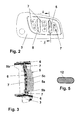
- eine Draufsicht auf eine obere Schale des Schlüssels der
Figur 1 , - Figur 3
- einen Schnitt A - A durch die Schale der
Figur 2 , - Figur 4
- einen Schnitt durch einen Teil eines Spritzguss- Werkzeugs und
- Figur 5
- einen alternativen Querschnitt eines Zentrierrings.
- Wie aus der
Figur 1 ersichtlich umfasst ein elektronischer Schlüssel ein Gehäuse 1, das aus einer unteren Schale 2 und einer oberen Schale 3 zusammengesetzt ist. An der oberen Schale 3 sind drei Tasten 4 zum Bedienen von Tastschaltern mit definierten Funktionen angeordnet. In dem Gehäuse 1 ist eine Leiterplatte mit elektrischen und/oder elektronischen Bauteilen, z.B. den Tastschaltern, angeordnet. Zwischen zwei benachbarten der Tasten 4 ist jeweils ein Steg 5 angeordnet, der ein versehentliches gleichzeitiges Drücken zweier der Tasten 4 verhindert. An dem Gehäuse 1 ist ein Halter für einen mechanischen Schlüsselbart 20 befestigt. - Wie aus den
Figuren 2 und 3 besonders deutlich wird, umfasst die obere Schale 3 einen Rahmen 6, in dem die hier zwei Stege 5 befestigt sind. Der Rahmen 6 weist Im Bereich der Tasten 4 in etwa einen Querschnitt eines breit gezogenen H auf, wobei das H zwei Stempel und eine die Stempel verbindende Brücke aufweist. Die Stege 5 erstrecken sich im Wesentlichen zwischen den Stempeln und parallel zu der Brücke. Weiterhin sind an dem Rahmen 6 Dichtungen 7 an vorbestimmten Stellen befestigt. Die Dichtung 7 deckt die komplette Innengeometrie der oberen Schale 3 ab und ist ebenfalls in deren äußeren Kontur unterhalb der Tasten 4 angeordnet. - Jeder der Stege 5 weist einen in etwa quaderförmigen länglichen Grundkörper 5a mit gerundeten Kanten auf, wobei an einer einem Inneren des Gehäuses 1 zugewandten Unterseite des Grundkörpers 5a zungenartige Laschen 5b angeformt sind. Die Laschen 5b erstrecken sich in Längsrichtung des Stegs 5 bis in den zugeordneten Stempel. An der Unterseite des Grundkörpers 5a ist ein Ring nach Art einer Hutkrempe angeformt. In der Fläche der Unterseite des Grundkörpers 5a ist in etwa zentrisch ein Dorn 5c angeformt. Die Laschen 5b und der Ring ist von dem Material des Rahmens 6 umschlossen, so dass die Stege fest in die obere Schale 3 integriert ist.
- Der Rahmen 6 ist aus hartem Kunststoff und die Dichtungen 7 sind aus weichem Kunststoff gefertigt. Die Stege 5 sind aus Zinkdruckguss gefertigt und verchromt.
- Die untere Schale 2 wird wie bekannt im Spritzguss aus Kunststoff gefertigt.
- Ein Werkzeug 10 zur Herstellung der oberen Schale 3 im Spritzguss ist ausschnittsweise mit eingelegtem Steg 5 in der
Figur 4 dargestellt. Das Werkzeug 10 umfasst für jeden der Stege 5 eine Aufnahme 11, die derart gestaltet ist, dass in ihr der Steg 5 bis zu dem Ring mit geringem Spiel aufgenommen werden kann. An einer Innenseite der Aufnahme 11 ist in der Nähe des Rings eine Nut eingelassen, in die ein Zentrierring 12 eingesetzt ist. Der Zentrierring 12 ragt aus der Innenseite für eine vorbestimmte Länge in das Innere der Aufnahme 11. Dieser Zentrierring gleicht das Spiel zwischen der Aufnahme 11 und dem Steh 5 aus. Der Innenseite der Aufnahme 11 gegenüber liegend ist ein Stempel 13 längs entsprechend dem Doppelpfeil 14 verfahrbar gelagert. Der Zentrierring 12 ist hier ein O-Ring. - Alternativ weist der Zentrierring 12 einen länglichen rechteckigen Querschnitt mit gerundeten Schmalseiten auf, wie er in der
Figur 5 dargestellt ist.. - Die Stege 5 werden im Zinkdruckguss vorgefertigt und verchromt. Die Stege 5 werden dann in die Aufnahme 11 eingelegt, durch den Zentrierring 12 in eine exakte vorbestimmte Position zentriert und durch den Stempel 13 im Bereich des Dorns 5c in diese mit vorbestimmter Kraft gedrückt. Anschließend wird der Rahmen 6 im Spritzguss geformt, wobei die Stege 5 teilweise - nämlich im Bereich ihrer Basis, das ist im Wesentlichen der Ring und die Laschen 5b - von dem Gussmaterial, also von hartem Kunststoff umschlossen werden. Hierdurch sind die Stege 5 stoffschlüssig fest in der oberen Schale 3 gehalten, also in die obere Schale 3 integriert. Der Stempel 13 wird von dem Steg 5 weg gezogen. Dann werden die Dichtungen 7 gespritzt, wobei auch die Stelle des Stegs 5, an der der Stempel 13 während des Spritzens des Rahmens 6 positioniert war, von der Dichtung 7 abgedeckt wird.
- Anschließend wird der elektronische Schlüssel wie bekannt fertig montiert: An der oberen Schale 3 werden die Tasten angeklebt. In die unteren Schale 2 wird die Leiterplatte und eine Batterie eingelegt. Die beiden Schalen 2, 3 werden du dem Gehäuse 1 zusammengesetzt und aneinander befestigt, wobei gleichzeitig eine Öse sowie der Halter für den mechanischen Schlüsselbart 20 in dem Gehäuse 1 gelagert wird. Das Befestigen erfolgt z.B. durch Laserschweißen.
-
- 1
- Gehäuse
- 2
- untere Schale
- 3
- obere Schale
- 4
- Taste
- 5
- Steg
- 5a
- Grundkörper
- 5b
- Lasche
- 5c
- Dorn
- 6
- Rahmen
- 7
- Dichtung
- 10
- Werkzeug
- 11
- Aufnahme
- 12
- Zentrierring
- 13
- Stempel
- 14
- Doppelpfeil
- 20
- Schlüsselbart
Claims (9)
- Elektronischer Schlüssel, umfassend
ein Gehäuse (1) aus Kunststoff, das aus zwei Schalen (2, 3) zusammengesetzt ist,
eine in dem Gehäuse (1) befestigte Leiterplatte mit elektrischen und/oder elektronischen Bauteilen, die Sende- und/oder Empfangsvorrichtungen sowie Tastschalter umfassen,
mindestens zwei Tasten (4), die von einer Außenseite des Gehäuses (1) bedienbar sind, wobei jede der Tasten (4) auf einen zugeordneten der Tastschalter wirkt,
wobei zwischen zwei benachbarten Tasten (4) jeweils ein in das Gehäuse (1) integrierter Steg (5) angeordnet ist,
dadurch gekennzeichnet, dass der Steg (5) aus Metall vorgefertigt ist und dass er von einer der Schalen (3) teilweise umspritzt ist. - Schlüssel nach Anspruch 1, dadurch gekennzeichnet, dass der Steg (5) aus beschichtetem Zinkdruckguss gefertigt ist.
- Schlüssel nach Anspruch 1 oder 2, dadurch gekennzeichnet, dass der Steg (5) verchromt ist.
- Schlüssel nach einem der Ansprüche 1 bis 3, dadurch gekennzeichnet, dass an einer der Innenseite des Gehäuses (1) zugeordneten Fläche des Stegs (5) ein Dorn (5c) ausgebildet ist.
- Spritzguss- Werkzeug zur Herstellung eines Schlüssels der Ansprüche 1 bis 4, dadurch gekennzeichnet, dass an einer Innenseite einer Aufnahme (11), die für den Steg (5) bestimmt ist, ein umlaufender Zentrierring (12) angeordnet ist.
- Werkzeug nach Anspruch 5, dadurch gekennzeichnet, dass der Zentrierring (12) so in eine entsprechende Nut eingesetzt ist, dass er aus der Fläche der Innenseite herausragt.
- Werkzeug nach Anspruch 4 oder 5, dadurch gekennzeichnet, dass der Zentrierring (12) ein O- Ring ist.
- Werkzeug nach Anspruch 4 oder 5, dadurch gekennzeichnet, dass der Zentrierring (12) einen länglichen rechteckigen Querschnitt mit gerundeten Schmalseiten aufweist.
- Verfahren zum Herstellen einer Schale (3) eines Schlüssels der Ansprüche 1 bis 4,
wobei die Schale (3) aus Kunststoff gespritzt wird,
dadurch gekennzeichnet, dass ein vorgefertigter Steg (5) aus Metall in eine zugeordnete Aufnahme (11) eines Spritzguss- Werkzeugs (10) eingelegt und hier mittels eines Stempels (13) unter vorbestimmtem Druck gehalten wird,
dass dann die Schale (3) aus hartem Kunststoff gespritzt wird, wobei der Steg (5) in einem Basisbereich umspritzt wird,
dass dann der Stempel (13) zurückgezogen wird und
dass schließlich Dichtungen (7) aus einem weichen Kunststoff an vorbestimmten Stellen der Schale (3) und des Stegs (5) aufgespritzt werden.
Priority Applications (1)
| Application Number | Priority Date | Filing Date | Title |
|---|---|---|---|
| EP10158936.4A EP2371513B1 (de) | 2010-04-01 | 2010-04-01 | Elektronischer Schlüssel |
Applications Claiming Priority (1)
| Application Number | Priority Date | Filing Date | Title |
|---|---|---|---|
| EP10158936.4A EP2371513B1 (de) | 2010-04-01 | 2010-04-01 | Elektronischer Schlüssel |
Publications (2)
| Publication Number | Publication Date |
|---|---|
| EP2371513A1 true EP2371513A1 (de) | 2011-10-05 |
| EP2371513B1 EP2371513B1 (de) | 2017-11-08 |
Family
ID=42320322
Family Applications (1)
| Application Number | Title | Priority Date | Filing Date |
|---|---|---|---|
| EP10158936.4A Active EP2371513B1 (de) | 2010-04-01 | 2010-04-01 | Elektronischer Schlüssel |
Country Status (1)
| Country | Link |
|---|---|
| EP (1) | EP2371513B1 (de) |
Cited By (1)
| Publication number | Priority date | Publication date | Assignee | Title |
|---|---|---|---|---|
| EP2610818A3 (de) * | 2011-12-30 | 2017-10-25 | Marquardt GmbH | "Gehäuse, insbesondere für einen elektronischen Schlüssel" |
Citations (10)
| Publication number | Priority date | Publication date | Assignee | Title |
|---|---|---|---|---|
| US4867663A (en) * | 1988-04-28 | 1989-09-19 | Ats Automation Tooling Systems Inc. | Seal for molded part insert |
| DE19915969A1 (de) * | 1998-04-28 | 1999-11-04 | Marquardt Gmbh | Gehäuseteil mit einem Betätigungsorgan |
| US6523380B1 (en) * | 2000-11-15 | 2003-02-25 | Strattec Security Corporation | Overmolded key including an ornamental element and method of making same |
| US20030042625A1 (en) * | 1999-11-05 | 2003-03-06 | Shin Kurosawa | Molding die set and semiconductor device fabricated using the same |
| WO2005035915A1 (de) * | 2003-09-16 | 2005-04-21 | Daimlerchrysler Ag | Elektronischer schlüssel |
| WO2005061204A1 (en) * | 2003-12-22 | 2005-07-07 | Perlos Oyj | Cover for portable electronic device and method for making the same |
| DE19605201B4 (de) | 1996-02-13 | 2007-04-12 | Marquardt Gmbh | Gehäuse für einen elektronischen Schlüssel |
| WO2007079896A1 (de) * | 2005-12-23 | 2007-07-19 | Huf Hülsbeck & Fürst Gmbh & Co. Kg | Elektronischer schlüssel für fahrzeuge |
| DE102006010896A1 (de) * | 2006-03-09 | 2007-09-13 | Witte-Velbert Gmbh & Co. Kg | Gehäuse eines Funkschlüssels |
| US20090128288A1 (en) * | 2007-11-21 | 2009-05-21 | Omron Corporation | Portable device |
-
2010
- 2010-04-01 EP EP10158936.4A patent/EP2371513B1/de active Active
Patent Citations (10)
| Publication number | Priority date | Publication date | Assignee | Title |
|---|---|---|---|---|
| US4867663A (en) * | 1988-04-28 | 1989-09-19 | Ats Automation Tooling Systems Inc. | Seal for molded part insert |
| DE19605201B4 (de) | 1996-02-13 | 2007-04-12 | Marquardt Gmbh | Gehäuse für einen elektronischen Schlüssel |
| DE19915969A1 (de) * | 1998-04-28 | 1999-11-04 | Marquardt Gmbh | Gehäuseteil mit einem Betätigungsorgan |
| US20030042625A1 (en) * | 1999-11-05 | 2003-03-06 | Shin Kurosawa | Molding die set and semiconductor device fabricated using the same |
| US6523380B1 (en) * | 2000-11-15 | 2003-02-25 | Strattec Security Corporation | Overmolded key including an ornamental element and method of making same |
| WO2005035915A1 (de) * | 2003-09-16 | 2005-04-21 | Daimlerchrysler Ag | Elektronischer schlüssel |
| WO2005061204A1 (en) * | 2003-12-22 | 2005-07-07 | Perlos Oyj | Cover for portable electronic device and method for making the same |
| WO2007079896A1 (de) * | 2005-12-23 | 2007-07-19 | Huf Hülsbeck & Fürst Gmbh & Co. Kg | Elektronischer schlüssel für fahrzeuge |
| DE102006010896A1 (de) * | 2006-03-09 | 2007-09-13 | Witte-Velbert Gmbh & Co. Kg | Gehäuse eines Funkschlüssels |
| US20090128288A1 (en) * | 2007-11-21 | 2009-05-21 | Omron Corporation | Portable device |
Cited By (1)
| Publication number | Priority date | Publication date | Assignee | Title |
|---|---|---|---|---|
| EP2610818A3 (de) * | 2011-12-30 | 2017-10-25 | Marquardt GmbH | "Gehäuse, insbesondere für einen elektronischen Schlüssel" |
Also Published As
| Publication number | Publication date |
|---|---|
| EP2371513B1 (de) | 2017-11-08 |
Similar Documents
| Publication | Publication Date | Title |
|---|---|---|
| DE102006041951B4 (de) | Wippschalter | |
| EP4025752B1 (de) | Betätigungsvorrichtung zur montage an einem fahrzeugteil, fahrzeug sowie betätigungsverfahren zum auslösen einer fahrzeugfunktion | |
| DE102008042722B4 (de) | Sensorgehäuse | |
| EP1075578B1 (de) | Gehäuseteil mit einem betätigungsorgan | |
| DE19964166C1 (de) | Gehäuse für Elektronikschlüssel | |
| EP2535489B1 (de) | Handhabe eines beweglichen Teils mit einer Elektronikbaugruppe, die an unterschiedlichen Bauteilen angeordnet ist | |
| EP1930925A1 (de) | Verfahren zur partiellen Galvanisierung eines durch Spritzgiessen hergestellten Dekor- oder Funktionsbauteil | |
| DE19715536C2 (de) | Griffgehäuse mit eingebautem Schalter und Verfahren zu dessen Herstellung | |
| WO2005008003A1 (de) | Griff für türen oder klappen an fahrzeugen | |
| EP1703528A2 (de) | Baueinheit mit elektrischer Schaltfunktion sowie Verfahren zum Herstellen einer solchen Baueinheit | |
| DE102007057934A1 (de) | Verfahren zum Herstellen eines auf zumindest einer Fläche kunststoffbeschichteten metallischen Bauteils | |
| DE102009056212A1 (de) | Elektronisches Bauteil hergestellt durch Spritzgießen, Verfahren und Werkzeug zur Herstellung desselben und elektronisches Gerät zur Verwendung desselben | |
| DE102009053384A1 (de) | Verfahren zur Herstellung eines Kraftfahrzeugtürschlosses und zugehöriges Kraftfahrzeugtürschloss | |
| EP2371513B1 (de) | Elektronischer Schlüssel | |
| DE102008042721B4 (de) | Sensorgehäuse | |
| DE102007041982A1 (de) | Verfahren zum Herstellen eines beschichteten Kunststoffhohlkörpers und Kunststoffformteil | |
| EP2877332B1 (de) | Verfahren zur herstellung eines kunststoffbauteils | |
| DE102009038304A1 (de) | Gehäuse, insbesondere für einen elektronischen Schlüssel | |
| DE19961370A1 (de) | Türaußengriffanordnung für eine Kraftfahrzeugtür, Kraftfahrzeugtür und Verfahren zur Montage eines Türaußengriffs | |
| DE102012105352A1 (de) | Positionierelement | |
| DE102006010896A1 (de) | Gehäuse eines Funkschlüssels | |
| DE29907642U1 (de) | Näherungsschalter mit keramischer Abdeckung | |
| EP3600971B1 (de) | Anzeigeelement, verfahren zur herstellung eines anzeigeelements und verwendung eines anzeigeelements und fahrzeug mit einem anzeigeelement | |
| EP2031356B1 (de) | Sensor | |
| WO2013098379A2 (de) | Gehäuse zur aufnahme einer elektronikeinheit |
Legal Events
| Date | Code | Title | Description |
|---|---|---|---|
| PUAI | Public reference made under article 153(3) epc to a published international application that has entered the european phase |
Free format text: ORIGINAL CODE: 0009012 |
|
| AK | Designated contracting states |
Kind code of ref document: A1 Designated state(s): AT BE BG CH CY CZ DE DK EE ES FI FR GB GR HR HU IE IS IT LI LT LU LV MC MK MT NL NO PL PT RO SE SI SK SM TR |
|
| AX | Request for extension of the european patent |
Extension state: AL BA ME RS |
|
| 17P | Request for examination filed |
Effective date: 20120404 |
|
| 17Q | First examination report despatched |
Effective date: 20140121 |
|
| REG | Reference to a national code |
Ref country code: DE Ref legal event code: R079 Ref document number: 502010014341 Country of ref document: DE Free format text: PREVIOUS MAIN CLASS: B29C0045160000 Ipc: B29L0031300000 |
|
| GRAP | Despatch of communication of intention to grant a patent |
Free format text: ORIGINAL CODE: EPIDOSNIGR1 |
|
| RIC1 | Information provided on ipc code assigned before grant |
Ipc: G07C 9/00 20060101ALI20170626BHEP Ipc: B29L 31/30 20060101AFI20170626BHEP Ipc: B29C 45/16 20060101ALI20170626BHEP |
|
| INTG | Intention to grant announced |
Effective date: 20170803 |
|
| GRAS | Grant fee paid |
Free format text: ORIGINAL CODE: EPIDOSNIGR3 |
|
| GRAA | (expected) grant |
Free format text: ORIGINAL CODE: 0009210 |
|
| AK | Designated contracting states |
Kind code of ref document: B1 Designated state(s): AT BE BG CH CY CZ DE DK EE ES FI FR GB GR HR HU IE IS IT LI LT LU LV MC MK MT NL NO PL PT RO SE SI SK SM TR |
|
| REG | Reference to a national code |
Ref country code: GB Ref legal event code: FG4D Free format text: NOT ENGLISH |
|
| REG | Reference to a national code |
Ref country code: CH Ref legal event code: EP Ref country code: AT Ref legal event code: REF Ref document number: 943739 Country of ref document: AT Kind code of ref document: T Effective date: 20171115 |
|
| REG | Reference to a national code |
Ref country code: IE Ref legal event code: FG4D Free format text: LANGUAGE OF EP DOCUMENT: GERMAN |
|
| REG | Reference to a national code |
Ref country code: DE Ref legal event code: R081 Ref document number: 502010014341 Country of ref document: DE Owner name: HELLA GMBH & CO. KGAA, DE Free format text: FORMER OWNER: HELLA KGAA HUECK & CO., 59557 LIPPSTADT, DE |
|
| RAP2 | Party data changed (patent owner data changed or rights of a patent transferred) |
Owner name: HELLA GMBH & CO. KGAA |
|
| REG | Reference to a national code |
Ref country code: DE Ref legal event code: R096 Ref document number: 502010014341 Country of ref document: DE |
|
| REG | Reference to a national code |
Ref country code: NL Ref legal event code: MP Effective date: 20171108 |
|
| REG | Reference to a national code |
Ref country code: FR Ref legal event code: PLFP Year of fee payment: 9 |
|
| REG | Reference to a national code |
Ref country code: LT Ref legal event code: MG4D |
|
| PG25 | Lapsed in a contracting state [announced via postgrant information from national office to epo] |
Ref country code: SE Free format text: LAPSE BECAUSE OF FAILURE TO SUBMIT A TRANSLATION OF THE DESCRIPTION OR TO PAY THE FEE WITHIN THE PRESCRIBED TIME-LIMIT Effective date: 20171108 Ref country code: LT Free format text: LAPSE BECAUSE OF FAILURE TO SUBMIT A TRANSLATION OF THE DESCRIPTION OR TO PAY THE FEE WITHIN THE PRESCRIBED TIME-LIMIT Effective date: 20171108 Ref country code: NO Free format text: LAPSE BECAUSE OF FAILURE TO SUBMIT A TRANSLATION OF THE DESCRIPTION OR TO PAY THE FEE WITHIN THE PRESCRIBED TIME-LIMIT Effective date: 20180208 Ref country code: NL Free format text: LAPSE BECAUSE OF FAILURE TO SUBMIT A TRANSLATION OF THE DESCRIPTION OR TO PAY THE FEE WITHIN THE PRESCRIBED TIME-LIMIT Effective date: 20171108 Ref country code: FI Free format text: LAPSE BECAUSE OF FAILURE TO SUBMIT A TRANSLATION OF THE DESCRIPTION OR TO PAY THE FEE WITHIN THE PRESCRIBED TIME-LIMIT Effective date: 20171108 Ref country code: ES Free format text: LAPSE BECAUSE OF FAILURE TO SUBMIT A TRANSLATION OF THE DESCRIPTION OR TO PAY THE FEE WITHIN THE PRESCRIBED TIME-LIMIT Effective date: 20171108 |
|
| PG25 | Lapsed in a contracting state [announced via postgrant information from national office to epo] |
Ref country code: LV Free format text: LAPSE BECAUSE OF FAILURE TO SUBMIT A TRANSLATION OF THE DESCRIPTION OR TO PAY THE FEE WITHIN THE PRESCRIBED TIME-LIMIT Effective date: 20171108 Ref country code: HR Free format text: LAPSE BECAUSE OF FAILURE TO SUBMIT A TRANSLATION OF THE DESCRIPTION OR TO PAY THE FEE WITHIN THE PRESCRIBED TIME-LIMIT Effective date: 20171108 Ref country code: IS Free format text: LAPSE BECAUSE OF FAILURE TO SUBMIT A TRANSLATION OF THE DESCRIPTION OR TO PAY THE FEE WITHIN THE PRESCRIBED TIME-LIMIT Effective date: 20180308 Ref country code: GR Free format text: LAPSE BECAUSE OF FAILURE TO SUBMIT A TRANSLATION OF THE DESCRIPTION OR TO PAY THE FEE WITHIN THE PRESCRIBED TIME-LIMIT Effective date: 20180209 Ref country code: BG Free format text: LAPSE BECAUSE OF FAILURE TO SUBMIT A TRANSLATION OF THE DESCRIPTION OR TO PAY THE FEE WITHIN THE PRESCRIBED TIME-LIMIT Effective date: 20180208 |
|
| PG25 | Lapsed in a contracting state [announced via postgrant information from national office to epo] |
Ref country code: EE Free format text: LAPSE BECAUSE OF FAILURE TO SUBMIT A TRANSLATION OF THE DESCRIPTION OR TO PAY THE FEE WITHIN THE PRESCRIBED TIME-LIMIT Effective date: 20171108 Ref country code: DK Free format text: LAPSE BECAUSE OF FAILURE TO SUBMIT A TRANSLATION OF THE DESCRIPTION OR TO PAY THE FEE WITHIN THE PRESCRIBED TIME-LIMIT Effective date: 20171108 Ref country code: CY Free format text: LAPSE BECAUSE OF FAILURE TO SUBMIT A TRANSLATION OF THE DESCRIPTION OR TO PAY THE FEE WITHIN THE PRESCRIBED TIME-LIMIT Effective date: 20171108 Ref country code: CZ Free format text: LAPSE BECAUSE OF FAILURE TO SUBMIT A TRANSLATION OF THE DESCRIPTION OR TO PAY THE FEE WITHIN THE PRESCRIBED TIME-LIMIT Effective date: 20171108 Ref country code: SK Free format text: LAPSE BECAUSE OF FAILURE TO SUBMIT A TRANSLATION OF THE DESCRIPTION OR TO PAY THE FEE WITHIN THE PRESCRIBED TIME-LIMIT Effective date: 20171108 |
|
| REG | Reference to a national code |
Ref country code: DE Ref legal event code: R097 Ref document number: 502010014341 Country of ref document: DE |
|
| PG25 | Lapsed in a contracting state [announced via postgrant information from national office to epo] |
Ref country code: PL Free format text: LAPSE BECAUSE OF FAILURE TO SUBMIT A TRANSLATION OF THE DESCRIPTION OR TO PAY THE FEE WITHIN THE PRESCRIBED TIME-LIMIT Effective date: 20171108 Ref country code: SM Free format text: LAPSE BECAUSE OF FAILURE TO SUBMIT A TRANSLATION OF THE DESCRIPTION OR TO PAY THE FEE WITHIN THE PRESCRIBED TIME-LIMIT Effective date: 20171108 Ref country code: IT Free format text: LAPSE BECAUSE OF FAILURE TO SUBMIT A TRANSLATION OF THE DESCRIPTION OR TO PAY THE FEE WITHIN THE PRESCRIBED TIME-LIMIT Effective date: 20171108 Ref country code: RO Free format text: LAPSE BECAUSE OF FAILURE TO SUBMIT A TRANSLATION OF THE DESCRIPTION OR TO PAY THE FEE WITHIN THE PRESCRIBED TIME-LIMIT Effective date: 20171108 |
|
| PLBE | No opposition filed within time limit |
Free format text: ORIGINAL CODE: 0009261 |
|
| STAA | Information on the status of an ep patent application or granted ep patent |
Free format text: STATUS: NO OPPOSITION FILED WITHIN TIME LIMIT |
|
| PG25 | Lapsed in a contracting state [announced via postgrant information from national office to epo] |
Ref country code: MT Free format text: LAPSE BECAUSE OF FAILURE TO SUBMIT A TRANSLATION OF THE DESCRIPTION OR TO PAY THE FEE WITHIN THE PRESCRIBED TIME-LIMIT Effective date: 20171108 |
|
| 26N | No opposition filed |
Effective date: 20180809 |
|
| PG25 | Lapsed in a contracting state [announced via postgrant information from national office to epo] |
Ref country code: MC Free format text: LAPSE BECAUSE OF FAILURE TO SUBMIT A TRANSLATION OF THE DESCRIPTION OR TO PAY THE FEE WITHIN THE PRESCRIBED TIME-LIMIT Effective date: 20171108 Ref country code: SI Free format text: LAPSE BECAUSE OF FAILURE TO SUBMIT A TRANSLATION OF THE DESCRIPTION OR TO PAY THE FEE WITHIN THE PRESCRIBED TIME-LIMIT Effective date: 20171108 |
|
| REG | Reference to a national code |
Ref country code: CH Ref legal event code: PL |
|
| REG | Reference to a national code |
Ref country code: BE Ref legal event code: MM Effective date: 20180430 |
|
| GBPC | Gb: european patent ceased through non-payment of renewal fee |
Effective date: 20180401 |
|
| REG | Reference to a national code |
Ref country code: IE Ref legal event code: MM4A |
|
| PG25 | Lapsed in a contracting state [announced via postgrant information from national office to epo] |
Ref country code: LU Free format text: LAPSE BECAUSE OF NON-PAYMENT OF DUE FEES Effective date: 20180401 |
|
| PG25 | Lapsed in a contracting state [announced via postgrant information from national office to epo] |
Ref country code: BE Free format text: LAPSE BECAUSE OF NON-PAYMENT OF DUE FEES Effective date: 20180430 Ref country code: CH Free format text: LAPSE BECAUSE OF NON-PAYMENT OF DUE FEES Effective date: 20180430 Ref country code: GB Free format text: LAPSE BECAUSE OF NON-PAYMENT OF DUE FEES Effective date: 20180401 Ref country code: LI Free format text: LAPSE BECAUSE OF NON-PAYMENT OF DUE FEES Effective date: 20180430 |
|
| PG25 | Lapsed in a contracting state [announced via postgrant information from national office to epo] |
Ref country code: IE Free format text: LAPSE BECAUSE OF NON-PAYMENT OF DUE FEES Effective date: 20180401 |
|
| REG | Reference to a national code |
Ref country code: AT Ref legal event code: MM01 Ref document number: 943739 Country of ref document: AT Kind code of ref document: T Effective date: 20180401 |
|
| PG25 | Lapsed in a contracting state [announced via postgrant information from national office to epo] |
Ref country code: AT Free format text: LAPSE BECAUSE OF NON-PAYMENT OF DUE FEES Effective date: 20180401 |
|
| PG25 | Lapsed in a contracting state [announced via postgrant information from national office to epo] |
Ref country code: TR Free format text: LAPSE BECAUSE OF FAILURE TO SUBMIT A TRANSLATION OF THE DESCRIPTION OR TO PAY THE FEE WITHIN THE PRESCRIBED TIME-LIMIT Effective date: 20171108 |
|
| PG25 | Lapsed in a contracting state [announced via postgrant information from national office to epo] |
Ref country code: HU Free format text: LAPSE BECAUSE OF FAILURE TO SUBMIT A TRANSLATION OF THE DESCRIPTION OR TO PAY THE FEE WITHIN THE PRESCRIBED TIME-LIMIT; INVALID AB INITIO Effective date: 20100401 Ref country code: PT Free format text: LAPSE BECAUSE OF FAILURE TO SUBMIT A TRANSLATION OF THE DESCRIPTION OR TO PAY THE FEE WITHIN THE PRESCRIBED TIME-LIMIT Effective date: 20171108 |
|
| PG25 | Lapsed in a contracting state [announced via postgrant information from national office to epo] |
Ref country code: MK Free format text: LAPSE BECAUSE OF NON-PAYMENT OF DUE FEES Effective date: 20171108 |
|
| PGFP | Annual fee paid to national office [announced via postgrant information from national office to epo] |
Ref country code: FR Payment date: 20200312 Year of fee payment: 11 |
|
| REG | Reference to a national code |
Ref country code: DE Ref legal event code: R084 Ref document number: 502010014341 Country of ref document: DE |
|
| PG25 | Lapsed in a contracting state [announced via postgrant information from national office to epo] |
Ref country code: FR Free format text: LAPSE BECAUSE OF NON-PAYMENT OF DUE FEES Effective date: 20210430 |
|
| PGFP | Annual fee paid to national office [announced via postgrant information from national office to epo] |
Ref country code: DE Payment date: 20260317 Year of fee payment: 17 |