EP2371486A1 - Rolling structure for sanding, grinding and surfacing work with built-in suction device - Google Patents
Rolling structure for sanding, grinding and surfacing work with built-in suction device Download PDFInfo
- Publication number
- EP2371486A1 EP2371486A1 EP11305341A EP11305341A EP2371486A1 EP 2371486 A1 EP2371486 A1 EP 2371486A1 EP 11305341 A EP11305341 A EP 11305341A EP 11305341 A EP11305341 A EP 11305341A EP 2371486 A1 EP2371486 A1 EP 2371486A1
- Authority
- EP
- European Patent Office
- Prior art keywords
- rolling structure
- structure according
- lower block
- block
- hose
- Prior art date
- Legal status (The legal status is an assumption and is not a legal conclusion. Google has not performed a legal analysis and makes no representation as to the accuracy of the status listed.)
- Withdrawn
Links
Images


Classifications
-
- B—PERFORMING OPERATIONS; TRANSPORTING
- B24—GRINDING; POLISHING
- B24B—MACHINES, DEVICES, OR PROCESSES FOR GRINDING OR POLISHING; DRESSING OR CONDITIONING OF ABRADING SURFACES; FEEDING OF GRINDING, POLISHING, OR LAPPING AGENTS
- B24B7/00—Machines or devices designed for grinding plane surfaces on work, including polishing plane glass surfaces; Accessories therefor
- B24B7/10—Single-purpose machines or devices
- B24B7/18—Single-purpose machines or devices for grinding floorings, walls, ceilings or the like
-
- B—PERFORMING OPERATIONS; TRANSPORTING
- B24—GRINDING; POLISHING
- B24B—MACHINES, DEVICES, OR PROCESSES FOR GRINDING OR POLISHING; DRESSING OR CONDITIONING OF ABRADING SURFACES; FEEDING OF GRINDING, POLISHING, OR LAPPING AGENTS
- B24B55/00—Safety devices for grinding or polishing machines; Accessories fitted to grinding or polishing machines for keeping tools or parts of the machine in good working condition
- B24B55/06—Dust extraction equipment on grinding or polishing machines
- B24B55/10—Dust extraction equipment on grinding or polishing machines specially designed for portable grinding machines, e.g. hand-guided
Definitions
- the invention relates to the technical sector of rolling structures of the trolley-serving type used in industry and building, arranged to allow at least suction operations of detritus, waste materials maintenance work, repair, shaping.
- trolleys In the field of construction and building, we also use trolleys for the same purpose, but in addition, are likely to receive power tools and also heavier and cumbersome equipment, such as hand sanders.
- the Applicant has for many years designed autonomous equipment and equipment that facilitates the work of operators during maintenance, renovation of walls, ceilings, construction and during finishing operations.
- These trolleys include one or more hand sanders, a vacuum block and offer the autonomy of use for the operator. These trolleys are arranged to allow storage and maintenance in the vertical position of the sanders or arms but also their removal to then allow to perform the work for which they are intended. In the context of the proposed solutions, the Applicant has also provided to be able to orient in position with appropriate supports the positioning, articulation and orientation of the above-mentioned arm sanders. Thus the Applicant has developed these rolling stock described especially in published French patents 2,882,913 , 2,893,875 , 2,896,715 , 2,928,571 , and not published 0 858 038 .
- a rolling stock forming a serving having a lower platform provided with rolling means and including in its rear part a vertical frame forming pre-emption handlebar and maneuvering.
- the vacuum unit is disposed on a platform of the carriage-serving while a surrounding housing allows the positioning and temporary and removable attachment of one or more hand sanders.
- the Applicant has endeavored to improve the integration of an aspiring system, and also facilitate in any circumstance the handling of these rolling stock.
- the rolling structure of the type comprising a trolley receiving a vacuum unit and a casing having in the upper part a service for receiving accessories
- the trolley-service comprises a housing central cylinder receiving internally a suction system and on each side at the end of said housing two opposite lower and upper blocks which are each arranged with rolling means and which define with said cylinder a set of parallelepiped volume can be moved on two wheels or four wheels in a vertical configuration on two wheels or in a horizontal configuration on four wheels, and in that said lower and upper blocks are arranged to receive in particular a grip handle and traction, and in that the lower block is arranged to allow the reception of a connection hose to the suction system and a means intended to function for the execution of work, and in that the upper block is arranged to receive the electric operating control means.
- the originality of the invention lies in the fact that the trolley-service is likely to be used and positioned according to the needs of the operator in two different positions without any modification of the structure.
- These two positions which are illustrated in particular in figures 1 and 3 relate respectively to the use and the displacement of the trolley in a known configuration for vacuum cleaners called vacuum cleaners-sleds commonly used for domestic households, with the difference that the trolley-serving according to the invention is movable in both positions .
- the other position is the more conventional where the carriage-service is in a vertical position according to the prior art previously recalled by allowing the use of the upper plate that can serve as a workbench.
- the trolley-service comprises a central cylindrical casing (2) receiving internally the suction system and on each end side of said casing two opposing blocks (3) and (4) which are each arranged with rolling means (5). ) and (6) and which define with said cylinder a set of parallelepipedal volume that can be moved on two wheels or four wheels depending on the conditions of use. This defines a lower block (3) and an upper block (4) whose functions will be specified.
- the lower block (3) is likely to be facing the ground when the carriage is in vertical position.
- This block (3) is arranged internally and optionally externally for receiving different components.
- the block is arranged with means and conduits that are connected to the suction source located inside the cylindrical housing (2), and also the positioning and development of a connecting hose (14) between a means (M) performing work such as a sander and the suction system.
- the lower block (3) has a square volumetric configuration.
- This lower block (3) has on the front an opening or cutout (3.3) for the passage of the hose (14) connection between the means (M) for performing work for the suction and the suction system.
- the lower block (3) incorporates in its rear housing for the positioning of the wheels (5) handling so that the assembly is perfectly integrated without exceeding the outer volume of the block.
- the lower block (3) has in its central part a circular cutout (3.6) corresponding to the section of the cylindrical housing of the suction system for its centering.
- the job execution means (M) is chosen by the operator according to his need. It can be a sanding tool, a sander, a suction brush or others being connected to the hose (14).
- cylindrical casing (2) is arranged for receiving a duct (9) suction.
- this duct is located outside the casing opening inside.
- Figures 4 and 5 this duct (9) is inside the cylindrical casing.
- connection duct (10) with a first end (10-1) for receiving the end of the hose (14).
- the other end (10-2) of this connecting pipe overflows into the suction duct (9) disposed inside the casing (1).
- the suction duct (9) is equipped with a fastener (11) for receiving a vacuum bag (12) disposed in the interior volume of the housing in whole or part thereof.
- the hose (14) is then spirally wound inside the lower block around the connecting pipe (10) which is thus shaped to facilitate this type of storage.
- the lower block adjusted internally with means allowing the automatic winding of the hose and locking in position.
- the lower block is equipped with a control knob (13) for winding the hose.
- one or more straps may be used to keep the turns of the coiled hose as horizontal as possible.
- the straps are attached in any appropriate manner to the interior walls of the lower block (3) and the conduit (10). connection.
- the upper block (4) has a volume similar to that of the lower block (3).
- the upper block also comprises a circular cutout (4.1) capable of fitting around the cylinder (2), the fixing taking place in any suitable manner in a removable configuration or not.
- This upper block is on its visible side a serving part (4.2) for storing tools or other accessories.
- the upper block receives the electrical equipment for the operation of the vacuum block and also the electrical connection sockets for the operation of the means (M) such as arm sander.
- the upper block can be arranged on one of its sides and preferably before to form a table (4.3) for electrical connection controls, safety lights, branch connectors and others.
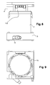
- the upper block (4) can be fitted internally alternatively as shown Figures 8-9 with the receipt of a winding device (15) of the electric winding cable allowing a winding of 4 to 5 meters of cable without brake.
- the two blocks (3) and (4) are arranged on their rear faces opposite to allow the positioning of a retractable handle (7), in the manner of the handles used on the bags, bags and the like, allowing their traction thanks to the incorporated rolling means.
- the lower block has two fixed ducts (8) from which the handle (7) can develop as shown in FIG. figure 3 .
- the trolley can be easily moved with the help of this handle which is then retracted when using the trolley or during storage.
- the trolley-service can be translated in the two represented positions which offers a big advantage for the operator.
- the trolley can be used for different purposes since it is sufficient to connect the hose (14) the tool in the means necessary to perform a task.
Landscapes
- Engineering & Computer Science (AREA)
- Mechanical Engineering (AREA)
- Finish Polishing, Edge Sharpening, And Grinding By Specific Grinding Devices (AREA)
- Storing, Repeated Paying-Out, And Re-Storing Of Elongated Articles (AREA)
Abstract
Description
L'invention se rattache au secteur technique des structures roulantes du type chariot-desserte utilisées dans l'industrie et le bâtiment, aménagées pour permettre au moins des opérations d'aspiration des détritus, matières usées de travaux d'entretien, réparation, façonnage.The invention relates to the technical sector of rolling structures of the trolley-serving type used in industry and building, arranged to allow at least suction operations of detritus, waste materials maintenance work, repair, shaping.
Le concept du chariot-desserte est déjà bien connu en soi en étant aménagé pour recevoir des outils ou autres accessoires nécessaires à des travaux en atelier pour les applications les plus diverses.The concept of the trolley-serving is already well known in itself being arranged to receive tools or other accessories necessary for workshop work for the most diverse applications.
Dans le domaine de la construction et du bâtiment, on utilise aussi des chariots-dessertes aux mêmes fins, mais qui en plus, sont susceptibles de recevoir de l'outillage électroportatif et aussi du matériel plus lourd et encombrant, telles les ponceuses à bras.In the field of construction and building, we also use trolleys for the same purpose, but in addition, are likely to receive power tools and also heavier and cumbersome equipment, such as hand sanders.
Le Demandeur a ainsi depuis plusieurs années conçu du matériel et des équipements autonomes qui facilitent le travail des opérateurs lors des opérations d'entretien, de rénovation de murs, de plafonds, de construction et lors d'opération de finition.As a result, the Applicant has for many years designed autonomous equipment and equipment that facilitates the work of operators during maintenance, renovation of walls, ceilings, construction and during finishing operations.
Ces chariots-dessertes incluent une ou plusieurs ponceuses à bras, un bloc aspirateur et offrent l'autonomie nécessaire d'utilisation pour l'opérateur. Ces chariots-dessertes sont agencés pour permettre le rangement et le maintien en position verticale de la ou des ponceuses à bras mais aussi leur enlèvement pour permettre ensuite d'effectuer les travaux auxquels elles sont destinées. Dans le cadre des solutions proposées, le Demandeur a aussi prévu de pouvoir orienter en position grâce à des supports appropriés le positionnement, l'articulation et l'orientation de la ou les ponceuses à bras précitées. Ainsi le Demandeur a développé ces matériels roulants décrits notamment dans les brevets français publiés
Il est donc ainsi connu de proposer un matériel roulant formant desserte présentant une plate-forme inférieure munie de moyens de roulement et incluant dans sa partie arrière un cadre vertical formant guidon de préemption et de manoeuvre. Le bloc aspirateur est disposé sur une plate-forme du chariot-desserte tandis qu'un carter entourant permet le positionnement et la fixation temporaire et démontable d'une ou de plusieurs ponceuses à bras.It is thus known to provide a rolling stock forming a serving having a lower platform provided with rolling means and including in its rear part a vertical frame forming pre-emption handlebar and maneuvering. The vacuum unit is disposed on a platform of the carriage-serving while a surrounding housing allows the positioning and temporary and removable attachment of one or more hand sanders.
La démarche du Demandeur a été encore d'optimiser la conception de ces structures roulantes à des fins d'utilisation variées, de rangement et de stockage, de réduction d'encombrement, et en laissant à l'opérateur la liberté d'utilisation à partir d'une structure roulante standard optimisée pour effectuer des tâches variées de simples aspirations, et de travaux à l'aide d'outils variés.The Applicant's approach has been to further optimize the design of these rolling structures for various purposes of use, storage and storage, reduction of space, and leaving the operator freedom of use from a standard rolling structure optimized to perform varied tasks of simple aspirations, and works using various tools.
Egalement, le Demandeur s'est attaché à améliorer l'intégration d'un système aspirant, et également faciliter en toute circonstance la manipulation de ces matériels roulants.Also, the Applicant has endeavored to improve the integration of an aspiring system, and also facilitate in any circumstance the handling of these rolling stock.
Selon une première caractéristique de l'invention, la structure roulante du type comprenant un chariot-desserte recevant un bloc aspirateur et un carter présentant en partie supérieure une desserte pour la réception d'accessoires est remarquable en ce que le chariot-desserte comprend un carter cylindrique central recevant intérieurement un système d'aspiration et de chaque côté en extrémité du dit carter deux blocs inférieur et supérieur opposés qui sont aménagés chacun avec des moyens de roulement et qui définissent avec le dit cylindre un ensemble de volume parallépipédique pouvant être mis en déplacement sur deux roues ou quatre roues dans une configuration verticale sur deux roues ou dans une configuration horizontale sur quatre roues, et en ce que les dits blocs inférieur et supérieur sont aménagés pour recevoir notamment une poignée de préhension et de traction, et en ce que le bloc inférieur est aménagé pour permettre la réception d'un flexible de raccordement au système d'aspiration et à un moyen destiné à fonctionner pour l'exécution de travaux, et en ce que le bloc supérieur est aménagé pour recevoir les moyens de commande électrique de fonctionnement.According to a first characteristic of the invention, the rolling structure of the type comprising a trolley receiving a vacuum unit and a casing having in the upper part a service for receiving accessories is remarkable in that the trolley-service comprises a housing central cylinder receiving internally a suction system and on each side at the end of said housing two opposite lower and upper blocks which are each arranged with rolling means and which define with said cylinder a set of parallelepiped volume can be moved on two wheels or four wheels in a vertical configuration on two wheels or in a horizontal configuration on four wheels, and in that said lower and upper blocks are arranged to receive in particular a grip handle and traction, and in that the lower block is arranged to allow the reception of a connection hose to the suction system and a means intended to function for the execution of work, and in that the upper block is arranged to receive the electric operating control means.
Ces caractéristiques et d'autres encore ressortiront bien de la suite de la description.These and other characteristics will be apparent from the rest of the description.
Pour fixer l'objet de l'invention illustrée d'une manière non limitative aux figures des dessins où :
- La
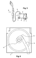
figure 1 est une vue de face d'une structure roulante formant chariot-desserte selon l'invention de roulement vertical, - La
figure 2 est une vue de côté de la structure de la structure roulante selon lafigure 1 , - La
figure 3 est une vue à caractère schématique de la structure roulante selon l'invention dans une autre position de roulement horizontal, - La
figure 4 est une vue de la structure roulante selon l'invention montrant une mise en oeuvre particulière de récupération et de stockage des détritus et des déchets. - La
figure 5 est une vue similaire à lafigure 4 mais de côté, - La
figure 6 est une vue à caractère schématique du dessous du bloc inférieur recevant le flexible associé à la ponceuse à bras et avant enroulement. - La
figure 7 est une vue complémentaire à lafigure 6 le flexible étant enroulé, - La
figure 8 est une vue du chariot-desserte avec la réception dans son bloc supérieur d'un dispositif d'enroulement de câble électrique, - La
figure 9 est une vue de dessus du bloc supérieur illustrant le positionnement du dispositif d'enroulement de câble électrique dans la configuration de lafigure 8 .
- The
figure 1 is a front view of a rolling structure forming a trolley according to the invention of vertical rolling, - The
figure 2 is a side view of the structure of the rolling structure according to thefigure 1 , - The
figure 3 is a schematic view of the rolling structure according to the invention in another horizontal rolling position, - The
figure 4 is a view of the rolling structure according to the invention showing a particular implementation of recovery and storage of detritus and waste. - The
figure 5 is a view similar to thefigure 4 but aside, - The
figure 6 is a schematic view of the underside of the lower block receiving the hose associated with the sander arm and before winding. - The
figure 7 is a complementary view to thefigure 6 the hose being wound, - The
figure 8 is a view of the trolley with the reception in its upper block of an electric cable winding device, - The
figure 9 is a top view of the upper block illustrating the positioning of the electric cable winding device in the configuration of thefigure 8 .
Afin de rendre plus concret l'objet de l'invention, on le décrit maintenant d'une manière non limitative illustrée aux figures des dessins.In order to make the object of the invention more concrete, it is now described in a nonlimiting manner illustrated in the figures of the drawings.
La structure roulante sous forme de chariot-desserte est référencée dans son ensemble par (1)The rolling structure in the form of trolley-service is referenced as a whole by (1)
L'originalité de l'invention réside dans le fait que le chariot-desserte est susceptible d'être utilisé et positionné selon les besoins de l'opérateur dans deux positions différentes sans aucune modification de la structure. Ces deux positions qui sont notamment illustrées aux
Ainsi le chariot-desserte comprend un carter cylindrique (2) central recevant intérieurement le système d'aspiration et de chaque côté en extrémité du dit carter deux blocs (3) et (4) opposés qui sont aménagés chacun avec des moyens de roulement (5) et (6) et qui définissent avec le dit cylindre un ensemble de volume parallépipédique pouvant être mis en déplacement sur deux roues ou quatre roues selon les conditions d'utilisation. On définit ainsi un bloc inférieur (3) et un bloc supérieur (4) dont les fonctions vont être précisées.Thus the trolley-service comprises a central cylindrical casing (2) receiving internally the suction system and on each end side of said casing two opposing blocks (3) and (4) which are each arranged with rolling means (5). ) and (6) and which define with said cylinder a set of parallelepipedal volume that can be moved on two wheels or four wheels depending on the conditions of use. This defines a lower block (3) and an upper block (4) whose functions will be specified.
Le bloc inférieur(3) est susceptible d'être en regard du sol lorsque le chariot-desserte est en position verticale. Ce bloc (3) est aménagé intérieurement et le cas échéant extérieurement pour la réception de différents composants. Intérieurement, le bloc est agencé avec des moyens et des conduits qui sont reliés à la source aspirante située à l'intérieur du carter cylindrique (2), et aussi le positionnement et le développement d'un flexible (14) de raccordement entre un moyen (M) d'exécution de travaux telle qu'une ponceuse à bras et le système aspirant. Extérieurement, le bloc inférieur (3) présente une configuration volumétrique carrée. Ce bloc inférieur (3) présente sur l'avant une ouverture ou découpe (3.3) permettant le passage du flexible (14) de raccordement entre le moyen (M) d'exécution de travaux pour l'aspiration et le système aspirant. Le bloc inférieur (3) intègre dans sa partie arrière des logements pour le positionnement des roues (5) de manutention de manière que l'ensemble soit parfaitement intégré sans dépassement extérieur par rapport au volume du bloc. En pratique, le bloc inférieur (3) présente dans sa partie centrale une découpe circulaire (3.6) correspondant à la section du carter cylindrique du système aspirant pour son centrage.The lower block (3) is likely to be facing the ground when the carriage is in vertical position. This block (3) is arranged internally and optionally externally for receiving different components. Internally, the block is arranged with means and conduits that are connected to the suction source located inside the cylindrical housing (2), and also the positioning and development of a connecting hose (14) between a means (M) performing work such as a sander and the suction system. Externally, the lower block (3) has a square volumetric configuration. This lower block (3) has on the front an opening or cutout (3.3) for the passage of the hose (14) connection between the means (M) for performing work for the suction and the suction system. The lower block (3) incorporates in its rear housing for the positioning of the wheels (5) handling so that the assembly is perfectly integrated without exceeding the outer volume of the block. In practice, the lower block (3) has in its central part a circular cutout (3.6) corresponding to the section of the cylindrical housing of the suction system for its centering.
Le moyen (M) d'exécution de travaux est choisi par l'opérateur en fonction de son besoin. Ce peut être un outil de ponçage, une ponceuse à bras, une brosse d'aspiration ou autres en étant relié au flexible (14).The job execution means (M) is chosen by the operator according to his need. It can be a sanding tool, a sander, a suction brush or others being connected to the hose (14).
En outre, le carter cylindrique (2) est aménagé pour la réception d'un conduit (9) d'aspiration.
Il est prévu dans le bloc inférieur (3) un conduit de raccordement (10) coudé en L avec une première extrémité (10-1) destinée à recevoir l'extrémité du flexible (14). L'autre extrémité (10-2) de ce conduit de raccordement déborde dans le conduit d'aspiration (9) disposé à l'intérieur du carter (1).There is provided in the lower block (3) an L-shaped connection duct (10) with a first end (10-1) for receiving the end of the hose (14). The other end (10-2) of this connecting pipe overflows into the suction duct (9) disposed inside the casing (1).
Le conduit d'aspiration (9) est équipé d'une attache (11) pour la réception d'un sac d'aspirateur (12) disposé dans le volume intérieur du carter en tout ou partie de celui-ci.The suction duct (9) is equipped with a fastener (11) for receiving a vacuum bag (12) disposed in the interior volume of the housing in whole or part thereof.
Le flexible (14) est ensuite enroulé en spirale à l'intérieur du bloc inférieur autour du conduit de raccordement (10) qui est ainsi profilé pour faciliter ce type de rangement.The hose (14) is then spirally wound inside the lower block around the connecting pipe (10) which is thus shaped to facilitate this type of storage.
Le bloc inférieur ajusté intérieurement avec des moyens permettant l'enroulement automatique du flexible et le verrouillage en position. A cet effet, le bloc inférieur est équipé d'un bouton de commande (13) d'enroulement du flexible.The lower block adjusted internally with means allowing the automatic winding of the hose and locking in position. For this purpose, the lower block is equipped with a control knob (13) for winding the hose.
Par ailleurs, une ou des sangles (non représentées) peuvent être utilisées pour maintenir le plus à l'horizontal les spires du flexible enroulé Les sangles sont fixées de toute manière appropriée aux parois intérieures du bloc inférieur (3) et du conduit (10) de raccordement.In addition, one or more straps (not shown) may be used to keep the turns of the coiled hose as horizontal as possible. The straps are attached in any appropriate manner to the interior walls of the lower block (3) and the conduit (10). connection.
Le bloc supérieur (4) présente un volume similaire à celui du bloc inférieur (3). Le bloc supérieur comprend aussi une découpe circulaire (4.1) susceptible de s'encastrer autour du cylindre (2), la fixation s'effectuant de toute manière appropriée dans une configuration démontable ou non. Ce bloc supérieur constitue sur sa face apparente une partie desserte (4.2) permettant le rangement d'outils ou autres accessoires. Dans son volume intérieur, le bloc supérieur reçoit l'équipement électrique permettant le fonctionnement du bloc aspirateur et aussi les prises de raccordement électrique pour le fonctionnement du moyen (M) telle que ponceuse à bras. A cet effet, le bloc supérieur peut être aménagé sur l'un de ses côtés et de préférence avant pour constituer un tableau (4.3) pour les commandes électriques de raccordement, de voyants de sécurité, connecteurs de branchement et autres.The upper block (4) has a volume similar to that of the lower block (3). The upper block also comprises a circular cutout (4.1) capable of fitting around the cylinder (2), the fixing taking place in any suitable manner in a removable configuration or not. This upper block is on its visible side a serving part (4.2) for storing tools or other accessories. In its interior volume, the upper block receives the electrical equipment for the operation of the vacuum block and also the electrical connection sockets for the operation of the means (M) such as arm sander. For this purpose, the upper block can be arranged on one of its sides and preferably before to form a table (4.3) for electrical connection controls, safety lights, branch connectors and others.
Selon une autre disposition, le bloc supérieur (4) peut-être aménagé intérieurement en variante comme représenté
Selon une autre disposition de l'invention, les deux blocs (3) et (4) sont aménagés sur leurs faces arrières en regard pour autoriser le positionnement d'une poignée (7) escamotable, à la manière des poignées utilisées sur les valises, sacs et similaires, permettant leur traction grâce aux moyens de roulement incorporés. Ainsi comme représenté aux dessins, le bloc inférieur présente deux conduits fixes (8) à partir desquels la poignée (7) peut se développer comme représenté à la
Les avantages ressortent bien de l'invention et on souligne en particulier la réduction du volume d'encombrement du chariot-desserte, son adaptabilité en deux positions d'utilisation et du roulement. On souligne aussi la réduction du volume d'encombrement des accessoires dû au rangement du flexible d'aspiration et du rangement du câble électrique.The advantages are apparent from the invention and in particular emphasizes the reduction of the volume of space of the trolley-service, its adaptability in two positions of use and the bearing. It also emphasizes the reduction of the volume of space of the accessories due to the storage of the suction hose and the storage of the electric cable.
Le chariot-desserte peut être utilisé à différentes fins puisqu'il suffit de raccorder au flexible (14) l'outil dans le moyen nécessaire à l'exécution d'une tâche.The trolley can be used for different purposes since it is sufficient to connect the hose (14) the tool in the means necessary to perform a task.
Claims (11)
Applications Claiming Priority (1)
| Application Number | Priority Date | Filing Date | Title |
|---|---|---|---|
| FR1052390A FR2958199B1 (en) | 2010-03-31 | 2010-03-31 | ROLLING STRUCTURE FOR SANDING, GRINDING, SURFACING WORK WITH INTEGRATED SUCTION DEVICE |
Publications (1)
| Publication Number | Publication Date |
|---|---|
| EP2371486A1 true EP2371486A1 (en) | 2011-10-05 |
Family
ID=42990319
Family Applications (1)
| Application Number | Title | Priority Date | Filing Date |
|---|---|---|---|
| EP11305341A Withdrawn EP2371486A1 (en) | 2010-03-31 | 2011-03-28 | Rolling structure for sanding, grinding and surfacing work with built-in suction device |
Country Status (2)
| Country | Link |
|---|---|
| EP (1) | EP2371486A1 (en) |
| FR (1) | FR2958199B1 (en) |
Citations (6)
| Publication number | Priority date | Publication date | Assignee | Title |
|---|---|---|---|---|
| FR858038A (en) | 1939-03-28 | 1940-11-15 | Andre Citroe N | Improvements to combustion engines |
| FR2882913A1 (en) | 2005-03-14 | 2006-09-15 | M B H Dev Sarl | Long reach sanding machine`s arranging, stocking and transporting structure, has rolling equipment with horizontal lower platform, where free space at front of platform receives aspirator block provided with two connection sockets |
| WO2006104321A1 (en) * | 2005-03-29 | 2006-10-05 | Daewoo Electronics Corporation | Multi-functional vacuum cleaner |
| FR2893875A3 (en) | 2005-11-28 | 2007-06-01 | M B H Dev Sarl | Long reach sanding machine storing and transporting structure for aspirating and removing e.g. dust, has case comprising upper plate with catch to authorize outlet for centralized air and fixation of hose and to direct air |
| FR2896715A1 (en) | 2006-02-02 | 2007-08-03 | M B H Dev Sarl | TRANSPORTABLE EQUIPMENT FOR GRINDING, SANDING, SURFACING, INCORPORATING A DEVICE OPERATING THROUGH DEPRESSION |
| FR2928571A1 (en) | 2008-03-12 | 2009-09-18 | M B H Dev Sarl | ROLLING STRUCTURE SUPPORT OF AT LEAST ONE SANDING TOOL AND SIMILAR FOR WORK ON WALLS AND CEILINGS |
-
2010
- 2010-03-31 FR FR1052390A patent/FR2958199B1/en not_active Expired - Fee Related
-
2011
- 2011-03-28 EP EP11305341A patent/EP2371486A1/en not_active Withdrawn
Patent Citations (6)
| Publication number | Priority date | Publication date | Assignee | Title |
|---|---|---|---|---|
| FR858038A (en) | 1939-03-28 | 1940-11-15 | Andre Citroe N | Improvements to combustion engines |
| FR2882913A1 (en) | 2005-03-14 | 2006-09-15 | M B H Dev Sarl | Long reach sanding machine`s arranging, stocking and transporting structure, has rolling equipment with horizontal lower platform, where free space at front of platform receives aspirator block provided with two connection sockets |
| WO2006104321A1 (en) * | 2005-03-29 | 2006-10-05 | Daewoo Electronics Corporation | Multi-functional vacuum cleaner |
| FR2893875A3 (en) | 2005-11-28 | 2007-06-01 | M B H Dev Sarl | Long reach sanding machine storing and transporting structure for aspirating and removing e.g. dust, has case comprising upper plate with catch to authorize outlet for centralized air and fixation of hose and to direct air |
| FR2896715A1 (en) | 2006-02-02 | 2007-08-03 | M B H Dev Sarl | TRANSPORTABLE EQUIPMENT FOR GRINDING, SANDING, SURFACING, INCORPORATING A DEVICE OPERATING THROUGH DEPRESSION |
| FR2928571A1 (en) | 2008-03-12 | 2009-09-18 | M B H Dev Sarl | ROLLING STRUCTURE SUPPORT OF AT LEAST ONE SANDING TOOL AND SIMILAR FOR WORK ON WALLS AND CEILINGS |
Also Published As
| Publication number | Publication date |
|---|---|
| FR2958199B1 (en) | 2012-08-03 |
| FR2958199A1 (en) | 2011-10-07 |
Similar Documents
| Publication | Publication Date | Title |
|---|---|---|
| EP2103381B1 (en) | Rolling structure supporting at least one sanding tool and similar for working on walls and ceilings | |
| EP2371485A1 (en) | Rolling structure for sanding and grinding work with built-in suction device | |
| FR2973360A1 (en) | Mobile crane i.e. remote controlled robotic multilifter for handling windows, has lever whose one end is pivotally mounted on boom and another end is connected to cylinder and connecting rod that is pivotally mounted to connecting part | |
| EP1702549B1 (en) | Structur for storing and transporting of at least one pole sander and its operating components | |
| EP2573297B1 (en) | Movable structure for handling and installing panels or plates onto walls or ceilings | |
| EP2501615A1 (en) | Carriage for the transport of an aircraft engine module | |
| EP2314422B1 (en) | Multifunctional mobile structure for maintenance works and renovation of walls and ceilings | |
| EP2191934B1 (en) | Movable structure for a grinding machine mounted on an arm for working on floors, walls and plinths with a device for governing and storing the grinding machine | |
| EP1800796B1 (en) | Support structure for a pole sander | |
| EP3002082A1 (en) | Improved floor sander | |
| FR2828875A1 (en) | Vehicle windscreen roadside/workshop maintenance , having suction section windscreen attached and which holds using double action arm moving guiding suction block along reentry path | |
| CN109073115A (en) | A kind of universal fixturing | |
| EP2535223A1 (en) | Arrangement of means for mounting and handling a retractable partition | |
| EP1702715A1 (en) | Pole sander with extension | |
| EP2371486A1 (en) | Rolling structure for sanding, grinding and surfacing work with built-in suction device | |
| FR2847222A1 (en) | Handling trolley for mounting air conditioners has horizontal lifting platform mounted on telescopic post to raise air conditioner into position | |
| EP3469169B1 (en) | Tool for cleaning a pool, particularly in a radioactive environment, comprising a tank | |
| US8844884B2 (en) | Wheeled structure for long arm tools connected to a suction block including a tilt device | |
| EP0433515A1 (en) | Floor, wall and ceiling washing, rinsing and drying machine | |
| FR2897551A1 (en) | Pole sander for e.g. buffing high ceiling, has arm with motor block integrated in case, and lighting unit arranged on base part of body of case to focus light beam in zone located behind head during starting and operation of sander | |
| KR20150087966A (en) | Coupling device of joint pipe and pressure | |
| FR2893875A3 (en) | Long reach sanding machine storing and transporting structure for aspirating and removing e.g. dust, has case comprising upper plate with catch to authorize outlet for centralized air and fixation of hose and to direct air | |
| FR3112358A3 (en) | Mobile device for moving a bucket | |
| FR3027245A1 (en) | HAND TOOL MACHINE HAVING A TOOL HOLDER RECEIVING A REPLACEABLE TOOL | |
| WO2023083748A1 (en) | Method for assembling a structure for a tool holder and an apparatus comprising said tool holder, and corresponding structure and apparatus |
Legal Events
| Date | Code | Title | Description |
|---|---|---|---|
| PUAI | Public reference made under article 153(3) epc to a published international application that has entered the european phase |
Free format text: ORIGINAL CODE: 0009012 |
|
| AK | Designated contracting states |
Kind code of ref document: A1 Designated state(s): AL AT BE BG CH CY CZ DE DK EE ES FI FR GB GR HR HU IE IS IT LI LT LU LV MC MK MT NL NO PL PT RO RS SE SI SK SM TR |
|
| AX | Request for extension of the european patent |
Extension state: BA ME |
|
| 17P | Request for examination filed |
Effective date: 20111017 |
|
| GRAP | Despatch of communication of intention to grant a patent |
Free format text: ORIGINAL CODE: EPIDOSNIGR1 |
|
| STAA | Information on the status of an ep patent application or granted ep patent |
Free format text: STATUS: THE APPLICATION IS DEEMED TO BE WITHDRAWN |
|
| 18D | Application deemed to be withdrawn |
Effective date: 20130726 |