EP2371069B1 - Agencement pour le transfert d'énergie sans contact - Google Patents
Agencement pour le transfert d'énergie sans contact Download PDFInfo
- Publication number
- EP2371069B1 EP2371069B1 EP09775099.6A EP09775099A EP2371069B1 EP 2371069 B1 EP2371069 B1 EP 2371069B1 EP 09775099 A EP09775099 A EP 09775099A EP 2371069 B1 EP2371069 B1 EP 2371069B1
- Authority
- EP
- European Patent Office
- Prior art keywords
- primary conductor
- arrangement according
- coupling
- carriage
- data transmission
- Prior art date
- Legal status (The legal status is an assumption and is not a legal conclusion. Google has not performed a legal analysis and makes no representation as to the accuracy of the status listed.)
- Active
Links
Images


Classifications
-
- H—ELECTRICITY
- H04—ELECTRIC COMMUNICATION TECHNIQUE
- H04B—TRANSMISSION
- H04B5/00—Near-field transmission systems, e.g. inductive or capacitive transmission systems
- H04B5/40—Near-field transmission systems, e.g. inductive or capacitive transmission systems characterised by components specially adapted for near-field transmission
- H04B5/48—Transceivers
-
- H—ELECTRICITY
- H04—ELECTRIC COMMUNICATION TECHNIQUE
- H04B—TRANSMISSION
- H04B5/00—Near-field transmission systems, e.g. inductive or capacitive transmission systems
- H04B5/20—Near-field transmission systems, e.g. inductive or capacitive transmission systems characterised by the transmission technique; characterised by the transmission medium
- H04B5/22—Capacitive coupling
-
- H—ELECTRICITY
- H04—ELECTRIC COMMUNICATION TECHNIQUE
- H04B—TRANSMISSION
- H04B5/00—Near-field transmission systems, e.g. inductive or capacitive transmission systems
- H04B5/20—Near-field transmission systems, e.g. inductive or capacitive transmission systems characterised by the transmission technique; characterised by the transmission medium
- H04B5/24—Inductive coupling
- H04B5/26—Inductive coupling using coils
- H04B5/266—One coil at each side, e.g. with primary and secondary coils
-
- H—ELECTRICITY
- H04—ELECTRIC COMMUNICATION TECHNIQUE
- H04B—TRANSMISSION
- H04B5/00—Near-field transmission systems, e.g. inductive or capacitive transmission systems
- H04B5/70—Near-field transmission systems, e.g. inductive or capacitive transmission systems specially adapted for specific purposes
- H04B5/79—Near-field transmission systems, e.g. inductive or capacitive transmission systems specially adapted for specific purposes for data transfer in combination with power transfer
Definitions
- the invention relates to an arrangement for contactless energy transfer.
- the invention has the object of developing an arrangement for contactless energy transfer with the simplest possible and cost-effective contactless data transmission.
- the object is achieved in the arrangement for contactless energy transfer according to the features specified in claim 1.
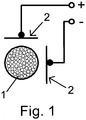
- the arrangement is provided for non-contact energy transmission, wherein an elongated laid primary conductor is provided, wherein at least one carriage which is movable along the primary conductor is provided, wherein on the carriage a means for data transmission is provided, wherein the primary conductor is composed of individual stranded wires provided against each other in an electrically insulated manner, wherein the means for data transmission comprises at least one coupling element, which is provided capacitively coupled to the stranded wires in such a way that signal voltages are input and / or decoupled into the stranded wires, wherein the coupling element comprises at least two coupling surfaces to which a voltage for transmitting data can be applied, wherein the normal directions of the coupling surfaces are oriented perpendicular to each other.
- the advantage here is that although separate coupling means are used for data transmission, but which are very inexpensive and easy to produce.
- the data transmission of the existing anyway for energy transfer, with AC of at least 10 kHz applied primary conductor is used.
- no additional line is necessary for the data transmission but it is possible to couple signals in the primary conductor inexpensively and easily and carry on.
- An essential feature of the primary conductor is its design of high-frequency stranded wire. According to the invention, it has been recognized that a capacitive coupling of signal voltages to a braid of high litz wires, which are individually insulated from one another, can be carried out.
- the stranded wires are each provided at their outer periphery with an electrical insulating layer.
- the advantage here is that by means of the capacitive coupling a locally different potential between different stranded wires can be generated. If the stranded wires were in electrically conductive contact, they would essentially always be at the same potential. By means of the electrical insulation, however, it can be achieved that different potentials are achieved and thus signal voltages can be coupled in, which exist between the stranded wires. Then, the signal voltages propagate in the direction of the primary conductor and are in corresponding manner detectable by means of corresponding coupling surfaces.
- the locally changing potentials of the stranded wires correspond to alternating currents according to Maxwell's equations, which is why in the present description there is essentially no finely differentiated between induced currents and these associated electric fields.
- the mentioned currents or voltages for signal transmission represent only additional proportions to the proportions which are necessary for power transmission.
- the dielectric strength of the insulation used in comparison to the total voltage occurring in this case is taken into account.
- the coupling element comprises at least two coupling surfaces to which a voltage can be applied, in particular for transmitting data. The advantage here is that an electric field can be formed, which induces the signal currents mentioned.
- the coupling element comprises at least two coupling surfaces, wherein the voltage applied between the coupling surfaces voltage can be detected, in particular for receiving data.
- the advantage here is that a detection of the signal currents or signal voltages is made possible in a simple manner.
- the coupling surfaces are made metallic and / or substantially planar.
- the advantage here is that a simple inexpensive design is sufficient.
- the normal directions of the coupling surfaces are oriented perpendicular to one another.
- the normal directions are also perpendicular to the direction of the primary conductor. The advantage here is that an inhomogeneous field arises in the region of the primary conductor and thus a particularly good signal-to-noise ratio can be achieved.
- the normal directions of the coupling surfaces are oriented parallel or at an angle of up to 40 ° to each other, in particular wherein the normal directions are also perpendicular to the direction of the primary conductor.
- the coupling element comprises a winding, wherein the associated magnetic field in the region of the primary conductor is inhomogeneous.
- the coupling element comprises a winding, wherein a substantial part of the magnetic field generated by the winding exits from the coupling element towards the primary conductor, in particular in a direction perpendicular to a direction of the primary conductor.
- the winding is provided around a leg of a ferrite core.
- a center leg of an E-shaped ferrite core in particular wherein the legs lie in a plane whose normal direction is provided perpendicular to the direction of the primary conductor.
- a stationarily arranged means for data transmission also comprises a corresponding coupling element, in particular wherein data transmission between one or more cars and the stationarily arranged means is provided.
- the carriage is provided with a secondary conductor inductively coupled to the secondary winding for supplying a provided on the car or connected to the car or electrically or magnetically coupled consumer.
- the car may for example have an electric drive, with which this car, so a vehicle, and / or a load provided on the car is movable.
- a stationarily arranged unit from the car for example, can be supplied inductively, thus allowing the car upon reaching the appropriate position, this further non-contact power transmission.
- an alternating current is impressed into the primary conductor, in particular with a frequency between 10 and 500 kHz, in particular with more than 1 or even 10 amperes.
- the advantage here is that High power in the range of kilowatts are transferable, whereby only small losses occur.
- the secondary winding has a capacitance connected in series or in parallel such that the associated resonant frequency essentially corresponds to the frequency of the alternating current impressed into the primary conductor.
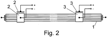
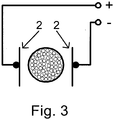
- FIG. 3 is another device with capacitive coupling in sectional view and in FIG. 4 shown in associated side view.
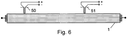
- FIG. 5 is a device with inductive coupling in sectional view and in FIG. 6 shown in associated side view.
- the primary conductor 1 is shown, which is designed elongated and in which an alternating current is impressed, preferably with a frequency between 10 and 500 kHz.
- a carriage is movably arranged, which comprises a secondary conductor inductively coupled to the primary coil 1, which is a capacitor connected in parallel or in series such that the associated resonant frequency substantially the frequency of the impressed in the primary conductor alternating current equivalent.
- the strength of the alternating current can exceed 1 or even 10 amperes permanently.
- means for data transmission are provided on this carriage which can be moved along the primary conductor 1.
- These include at least those in the FIGS. 1 and 2 These are designed as rectangular metal plates whose normal direction are oriented perpendicular to each other and perpendicular to the primary conductor direction.
- the primary conductor consists of a number of stranded wires, which are each made electrically insulated from each other.
- FIG. 2 Further analogously executed coupling surfaces 3 are shown, which are connected to a voltage detecting means, whereby thus the applied voltage between the metal plates is detected.
- the coupling surfaces 3 are arranged either on a further movable carriage or stationary.
- a voltage detection means and the coupling surfaces 3 a high-frequency AC voltage source connected to then allow in this way a bidirectional data transmission.
- Different frequency bands can be used for the data transmission, preferably above 10 MHz up to 10 GHz.
- FIG. 5 is an inductive coupling of the data instead of in the FIGS. 1 and 3 shown shown capacitive coupling.
- an E-shaped ferrite core 50 is used whose center leg of the E is made much narrower than the two outer limbs of the E.
- a coupling winding is provided around the center leg, with the magnetic field lines emerging from the ferrite core 50 issuing substantially directed towards the center of the primary conductor.
- the center leg is oriented perpendicular to the direction of the primary conductor 50.
- the alternating magnetic field lines passing through the primary conductor induce electric fields, so that in turn a corresponding polarization can be generated. It is also important that in the region of the primary conductor a very inhomogeneous magnetic field is provided, that is, the magnetic field strength drops sharply in at least one direction.
- a current source and current detection means At the winding provided around the center leg, preferably instead of the according to FIGS. 1 to 4 provided voltage source and voltage detection means a current source and current detection means.
- the second ferrite core is designated by reference numeral 51.
- the geometric extent of the E is dependent on the diameter of the primary conductor 1 and the distance of the end portion of the center leg of the E from the primary conductor. 1
- a corresponding other geometry can also be selected. It is essential here that the inhomogeneous field described above can be generated within the cross section of the primary conductor.
Landscapes
- Engineering & Computer Science (AREA)
- Computer Networks & Wireless Communication (AREA)
- Signal Processing (AREA)
- Near-Field Transmission Systems (AREA)
Claims (9)
- Dispositif dévolu au transfert d'énergie sans contact,
sachant qu'il est prévu un conducteur primaire posé avec étendue en longueur,
sachant qu'il est prévu au moins un chariot pouvant être déplacé le long dudit conducteur primaire,
sachant qu'un moyen, affecté au transfert de données, est prévu sur ledit chariot,
ledit conducteur primaire étant composé de fils torsadés individuels, prévus avec isolation électrique les uns par rapport aux autres,
caractérisé par le fait que
le moyen, affecté au transfert de données, englobe au moins un élément de couplage prévu avec couplage capacitif aux fils torsadés, de façon telle que des tensions de signaux puissent être induites dans lesdits fils torsadés, et/ou extraites de ces derniers,
ledit élément de couplage incluant au moins deux surfaces de couplage auxquelles une tension peut être appliquée, en vue de l'émission de données,
les directions des normales desdites surfaces de couplage étant orientées avec perpendicularité mutuelle. - Dispositif selon la revendication 1,
caractérisé par le fait que
les fils torsadés sont respectivement dotés d'une couche d'isolation électrique sur leur pourtour extérieur. - Dispositif selon au moins l'une des revendications précédentes, caractérisé par le fait que
l'élément de couplage inclut au moins deux surfaces de couplage, sachant que la tension appliquée entre lesdites surfaces de couplage peut être détectée, notamment en vue de la réception de données. - Dispositif selon au moins l'une des revendications précédentes, caractérisé par le fait que
les surfaces de couplage sont de réalisation métallique, et/ou plane pour l'essentiel. - Dispositif selon au moins l'une des revendications précédentes, caractérisé par le fait que
les directions des normales sont également perpendiculaires à la direction du conducteur primaire. - Dispositif selon au moins l'une des revendications précédentes, caractérisé par le fait
qu'un moyen à implantation stationnaire, affecté au transfert de données, englobe pareillement un élément de couplage correspondant, sachant notamment qu'un transfert de données est prévu entre ledit moyen à implantation stationnaire et un ou plusieurs chariot(s). - Dispositif selon au moins l'une des revendications précédentes, caractérisé par le fait
qu'un enroulement secondaire, couplé inductivement au conducteur primaire, est prévu sur le chariot afin d'alimenter un appareil consommateur prévu sur ledit chariot ou raccordé audit chariot, voire couplé électriquement ou magnétiquement. - Dispositif selon au moins l'une des revendications précédentes, caractérisé par le fait
qu'un courant alternatif présentant, en particulier, une fréquence comprise entre 10 et 500 kHz et mesurant notamment plus de 1, voire même 10 ampères, est injecté dans le conducteur primaire. - Dispositif selon la revendication 7,
caractérisé par le fait
qu'un condensateur est branché en série ou en parallèle avec l'enroulement secondaire, de façon telle que la fréquence de résonance associée corresponde, pour l'essentiel, à la fréquence du courant alternatif injecté dans le conducteur primaire.
Applications Claiming Priority (2)
| Application Number | Priority Date | Filing Date | Title |
|---|---|---|---|
| DE102008059091A DE102008059091B4 (de) | 2008-11-26 | 2008-11-26 | Anordnung zur berührungslosen Energieübertragung |
| PCT/EP2009/008352 WO2010060593A1 (fr) | 2008-11-26 | 2009-11-24 | Agencement pour le transfert d'énergie sans contact |
Publications (2)
| Publication Number | Publication Date |
|---|---|
| EP2371069A1 EP2371069A1 (fr) | 2011-10-05 |
| EP2371069B1 true EP2371069B1 (fr) | 2017-08-02 |
Family
ID=41611209
Family Applications (1)
| Application Number | Title | Priority Date | Filing Date |
|---|---|---|---|
| EP09775099.6A Active EP2371069B1 (fr) | 2008-11-26 | 2009-11-24 | Agencement pour le transfert d'énergie sans contact |
Country Status (3)
| Country | Link |
|---|---|
| EP (1) | EP2371069B1 (fr) |
| DE (2) | DE102008064673B4 (fr) |
| WO (1) | WO2010060593A1 (fr) |
Families Citing this family (3)
| Publication number | Priority date | Publication date | Assignee | Title |
|---|---|---|---|---|
| DE102010008858B4 (de) | 2010-02-22 | 2013-01-17 | Sew-Eurodrive Gmbh & Co. Kg | Anordnung zur berührungslosen Energieübertragung |
| DE102010009073B4 (de) | 2010-02-23 | 2013-01-17 | Sew-Eurodrive Gmbh & Co. Kg | Anordnung zur berührungslosen Energieübertragung |
| US10692646B2 (en) | 2017-07-19 | 2020-06-23 | Toyota Motor Engineering & Manufacturing North America, Inc. | Single litz wire transformers |
Citations (2)
| Publication number | Priority date | Publication date | Assignee | Title |
|---|---|---|---|---|
| DE102005008555A1 (de) * | 2005-02-23 | 2006-08-24 | Sew-Eurodrive Gmbh & Co. Kg | Anlage und Verfahren zur Bestimmung einer Position |
| WO2008058627A2 (fr) * | 2006-11-17 | 2008-05-22 | Sew-Eurodrive Gmbh & Co. Kg | Machine ou dispositif et procédé |
Family Cites Families (7)
| Publication number | Priority date | Publication date | Assignee | Title |
|---|---|---|---|---|
| US5293308A (en) * | 1991-03-26 | 1994-03-08 | Auckland Uniservices Limited | Inductive power distribution system |
| DE4446779C2 (de) * | 1994-12-24 | 1996-12-19 | Daimler Benz Ag | Anordnung zur berührungslosen induktiven Übertragung elektrischer Leistung |
| WO1999050806A1 (fr) * | 1998-04-01 | 1999-10-07 | Barret Massey Cunningham | Systeme de signalisation base sur un courant d'induction et le transfert de signaux |
| WO2004090918A1 (fr) * | 2003-04-07 | 2004-10-21 | Auckland Uniservices Limited | Systeme de communication pour systemes d'alimentation inductifs |
| DE102004031580B4 (de) * | 2004-06-29 | 2007-02-01 | Sew-Eurodrive Gmbh & Co. Kg | Anordnung zur berührungslosen induktiven Energieübertragung an bewegbare Vorrichtungen |
| DE102007051917B4 (de) * | 2006-11-27 | 2017-03-30 | Sew-Eurodrive Gmbh & Co Kg | Aktor, insbesondere Linearantrieb, und Anlage oder Maschine |
| DE102007059046B3 (de) | 2007-12-06 | 2009-04-30 | Sew-Eurodrive Gmbh & Co. Kg | Vorrichtung zur berührungslosen Energieübertragung und Anlage mit elektrischen Verbrauchern |
-
2008
- 2008-11-26 DE DE102008064673A patent/DE102008064673B4/de active Active
- 2008-11-26 DE DE102008059091A patent/DE102008059091B4/de active Active
-
2009
- 2009-11-24 EP EP09775099.6A patent/EP2371069B1/fr active Active
- 2009-11-24 WO PCT/EP2009/008352 patent/WO2010060593A1/fr not_active Ceased
Patent Citations (2)
| Publication number | Priority date | Publication date | Assignee | Title |
|---|---|---|---|---|
| DE102005008555A1 (de) * | 2005-02-23 | 2006-08-24 | Sew-Eurodrive Gmbh & Co. Kg | Anlage und Verfahren zur Bestimmung einer Position |
| WO2008058627A2 (fr) * | 2006-11-17 | 2008-05-22 | Sew-Eurodrive Gmbh & Co. Kg | Machine ou dispositif et procédé |
Also Published As
| Publication number | Publication date |
|---|---|
| DE102008064673B4 (de) | 2013-05-29 |
| DE102008064673A1 (de) | 2010-09-09 |
| DE102008059091A1 (de) | 2010-06-02 |
| WO2010060593A1 (fr) | 2010-06-03 |
| EP2371069A1 (fr) | 2011-10-05 |
| DE102008059091B4 (de) | 2010-09-30 |
Similar Documents
| Publication | Publication Date | Title |
|---|---|---|
| EP2225814B1 (fr) | Dispositif de transmission d'énergie sans contact et installation dotée de consommateurs électriques | |
| DE10344144B4 (de) | Anordnung zur berührungslosen induktiven Übertragung elektrischer Leistung | |
| EP2673157B1 (fr) | Dispositif de transmission d'énergie et de communication par induction | |
| DE102008064673B4 (de) | Anordnung zur berührungslosen Energieübertragung | |
| DE102007023343A1 (de) | Übertragerkopf und Anlage | |
| EP2700140B1 (fr) | Système de transmission inductive d'énergie à un récepteur électrique | |
| EP2029386B1 (fr) | Procédé et dispositif pour fabriquer un module électronique et module électronique | |
| DE102007024293B4 (de) | Anlage mit Primärleitersystem und bewegbar angeordneter Vorrichtung | |
| DE102006025460B4 (de) | Anlage mit einem Primärleitersystem | |
| EP4018464B1 (fr) | Système de transfert de puissance sans contact d'une ligne primaire à un enroulement | |
| EP1855909B1 (fr) | Installation et procédé pour déterminer une position | |
| EP2540003B1 (fr) | Système de transmission d'énergie sans contact | |
| EP3323134B1 (fr) | Ensemble de transmission d'énergie par induction d'un système conducteur primaire à un véhicule présentant un enroulement secondaire | |
| DE19957621A1 (de) | Anordnung zur Übertragung elektrischer Signale zwischen bewegten Teilen mit verringerter Wegezahl | |
| EP2540004B1 (fr) | Dispositif de transfert d'énergie sans contact | |
| DE102006025461B4 (de) | Übertragerkopf für eine Anlage zur berührungslosen Energieübertragung und Anlage mit einem Übertragerkopf | |
| EP3544707B1 (fr) | Circuit de voitures miniatures | |
| WO2025256805A1 (fr) | Système de transport comprenant une partie de profil de rail |
Legal Events
| Date | Code | Title | Description |
|---|---|---|---|
| PUAI | Public reference made under article 153(3) epc to a published international application that has entered the european phase |
Free format text: ORIGINAL CODE: 0009012 |
|
| 17P | Request for examination filed |
Effective date: 20110627 |
|
| AK | Designated contracting states |
Kind code of ref document: A1 Designated state(s): AT BE BG CH CY CZ DE DK EE ES FI FR GB GR HR HU IE IS IT LI LT LU LV MC MK MT NL NO PL PT RO SE SI SK SM TR |
|
| DAX | Request for extension of the european patent (deleted) | ||
| GRAP | Despatch of communication of intention to grant a patent |
Free format text: ORIGINAL CODE: EPIDOSNIGR1 |
|
| INTG | Intention to grant announced |
Effective date: 20170324 |
|
| GRAS | Grant fee paid |
Free format text: ORIGINAL CODE: EPIDOSNIGR3 |
|
| GRAA | (expected) grant |
Free format text: ORIGINAL CODE: 0009210 |
|
| AK | Designated contracting states |
Kind code of ref document: B1 Designated state(s): AT BE BG CH CY CZ DE DK EE ES FI FR GB GR HR HU IE IS IT LI LT LU LV MC MK MT NL NO PL PT RO SE SI SK SM TR |
|
| REG | Reference to a national code |
Ref country code: GB Ref legal event code: FG4D Free format text: NOT ENGLISH |
|
| REG | Reference to a national code |
Ref country code: CH Ref legal event code: EP Ref country code: AT Ref legal event code: REF Ref document number: 915504 Country of ref document: AT Kind code of ref document: T Effective date: 20170815 |
|
| REG | Reference to a national code |
Ref country code: IE Ref legal event code: FG4D Free format text: LANGUAGE OF EP DOCUMENT: GERMAN |
|
| REG | Reference to a national code |
Ref country code: DE Ref legal event code: R096 Ref document number: 502009014225 Country of ref document: DE |
|
| REG | Reference to a national code |
Ref country code: FR Ref legal event code: PLFP Year of fee payment: 9 |
|
| REG | Reference to a national code |
Ref country code: NL Ref legal event code: MP Effective date: 20170802 |
|
| REG | Reference to a national code |
Ref country code: LT Ref legal event code: MG4D |
|
| PG25 | Lapsed in a contracting state [announced via postgrant information from national office to epo] |
Ref country code: NL Free format text: LAPSE BECAUSE OF FAILURE TO SUBMIT A TRANSLATION OF THE DESCRIPTION OR TO PAY THE FEE WITHIN THE PRESCRIBED TIME-LIMIT Effective date: 20170802 Ref country code: LT Free format text: LAPSE BECAUSE OF FAILURE TO SUBMIT A TRANSLATION OF THE DESCRIPTION OR TO PAY THE FEE WITHIN THE PRESCRIBED TIME-LIMIT Effective date: 20170802 Ref country code: HR Free format text: LAPSE BECAUSE OF FAILURE TO SUBMIT A TRANSLATION OF THE DESCRIPTION OR TO PAY THE FEE WITHIN THE PRESCRIBED TIME-LIMIT Effective date: 20170802 Ref country code: SE Free format text: LAPSE BECAUSE OF FAILURE TO SUBMIT A TRANSLATION OF THE DESCRIPTION OR TO PAY THE FEE WITHIN THE PRESCRIBED TIME-LIMIT Effective date: 20170802 Ref country code: NO Free format text: LAPSE BECAUSE OF FAILURE TO SUBMIT A TRANSLATION OF THE DESCRIPTION OR TO PAY THE FEE WITHIN THE PRESCRIBED TIME-LIMIT Effective date: 20171102 Ref country code: FI Free format text: LAPSE BECAUSE OF FAILURE TO SUBMIT A TRANSLATION OF THE DESCRIPTION OR TO PAY THE FEE WITHIN THE PRESCRIBED TIME-LIMIT Effective date: 20170802 |
|
| PG25 | Lapsed in a contracting state [announced via postgrant information from national office to epo] |
Ref country code: LV Free format text: LAPSE BECAUSE OF FAILURE TO SUBMIT A TRANSLATION OF THE DESCRIPTION OR TO PAY THE FEE WITHIN THE PRESCRIBED TIME-LIMIT Effective date: 20170802 Ref country code: ES Free format text: LAPSE BECAUSE OF FAILURE TO SUBMIT A TRANSLATION OF THE DESCRIPTION OR TO PAY THE FEE WITHIN THE PRESCRIBED TIME-LIMIT Effective date: 20170802 Ref country code: GR Free format text: LAPSE BECAUSE OF FAILURE TO SUBMIT A TRANSLATION OF THE DESCRIPTION OR TO PAY THE FEE WITHIN THE PRESCRIBED TIME-LIMIT Effective date: 20171103 Ref country code: BG Free format text: LAPSE BECAUSE OF FAILURE TO SUBMIT A TRANSLATION OF THE DESCRIPTION OR TO PAY THE FEE WITHIN THE PRESCRIBED TIME-LIMIT Effective date: 20171102 Ref country code: PL Free format text: LAPSE BECAUSE OF FAILURE TO SUBMIT A TRANSLATION OF THE DESCRIPTION OR TO PAY THE FEE WITHIN THE PRESCRIBED TIME-LIMIT Effective date: 20170802 Ref country code: IS Free format text: LAPSE BECAUSE OF FAILURE TO SUBMIT A TRANSLATION OF THE DESCRIPTION OR TO PAY THE FEE WITHIN THE PRESCRIBED TIME-LIMIT Effective date: 20171202 |
|
| PG25 | Lapsed in a contracting state [announced via postgrant information from national office to epo] |
Ref country code: DK Free format text: LAPSE BECAUSE OF FAILURE TO SUBMIT A TRANSLATION OF THE DESCRIPTION OR TO PAY THE FEE WITHIN THE PRESCRIBED TIME-LIMIT Effective date: 20170802 Ref country code: RO Free format text: LAPSE BECAUSE OF FAILURE TO SUBMIT A TRANSLATION OF THE DESCRIPTION OR TO PAY THE FEE WITHIN THE PRESCRIBED TIME-LIMIT Effective date: 20170802 Ref country code: CZ Free format text: LAPSE BECAUSE OF FAILURE TO SUBMIT A TRANSLATION OF THE DESCRIPTION OR TO PAY THE FEE WITHIN THE PRESCRIBED TIME-LIMIT Effective date: 20170802 |
|
| REG | Reference to a national code |
Ref country code: DE Ref legal event code: R097 Ref document number: 502009014225 Country of ref document: DE |
|
| PG25 | Lapsed in a contracting state [announced via postgrant information from national office to epo] |
Ref country code: SK Free format text: LAPSE BECAUSE OF FAILURE TO SUBMIT A TRANSLATION OF THE DESCRIPTION OR TO PAY THE FEE WITHIN THE PRESCRIBED TIME-LIMIT Effective date: 20170802 Ref country code: SM Free format text: LAPSE BECAUSE OF FAILURE TO SUBMIT A TRANSLATION OF THE DESCRIPTION OR TO PAY THE FEE WITHIN THE PRESCRIBED TIME-LIMIT Effective date: 20170802 Ref country code: EE Free format text: LAPSE BECAUSE OF FAILURE TO SUBMIT A TRANSLATION OF THE DESCRIPTION OR TO PAY THE FEE WITHIN THE PRESCRIBED TIME-LIMIT Effective date: 20170802 Ref country code: IT Free format text: LAPSE BECAUSE OF FAILURE TO SUBMIT A TRANSLATION OF THE DESCRIPTION OR TO PAY THE FEE WITHIN THE PRESCRIBED TIME-LIMIT Effective date: 20170802 |
|
| PLBE | No opposition filed within time limit |
Free format text: ORIGINAL CODE: 0009261 |
|
| STAA | Information on the status of an ep patent application or granted ep patent |
Free format text: STATUS: NO OPPOSITION FILED WITHIN TIME LIMIT |
|
| PG25 | Lapsed in a contracting state [announced via postgrant information from national office to epo] |
Ref country code: MC Free format text: LAPSE BECAUSE OF FAILURE TO SUBMIT A TRANSLATION OF THE DESCRIPTION OR TO PAY THE FEE WITHIN THE PRESCRIBED TIME-LIMIT Effective date: 20170802 |
|
| 26N | No opposition filed |
Effective date: 20180503 |
|
| PG25 | Lapsed in a contracting state [announced via postgrant information from national office to epo] |
Ref country code: LI Free format text: LAPSE BECAUSE OF NON-PAYMENT OF DUE FEES Effective date: 20171130 Ref country code: CH Free format text: LAPSE BECAUSE OF NON-PAYMENT OF DUE FEES Effective date: 20171130 |
|
| PG25 | Lapsed in a contracting state [announced via postgrant information from national office to epo] |
Ref country code: SI Free format text: LAPSE BECAUSE OF FAILURE TO SUBMIT A TRANSLATION OF THE DESCRIPTION OR TO PAY THE FEE WITHIN THE PRESCRIBED TIME-LIMIT Effective date: 20170802 Ref country code: LU Free format text: LAPSE BECAUSE OF NON-PAYMENT OF DUE FEES Effective date: 20171124 |
|
| REG | Reference to a national code |
Ref country code: BE Ref legal event code: MM Effective date: 20171130 |
|
| REG | Reference to a national code |
Ref country code: IE Ref legal event code: MM4A |
|
| PG25 | Lapsed in a contracting state [announced via postgrant information from national office to epo] |
Ref country code: MT Free format text: LAPSE BECAUSE OF FAILURE TO SUBMIT A TRANSLATION OF THE DESCRIPTION OR TO PAY THE FEE WITHIN THE PRESCRIBED TIME-LIMIT Effective date: 20170802 |
|
| REG | Reference to a national code |
Ref country code: FR Ref legal event code: PLFP Year of fee payment: 10 |
|
| PG25 | Lapsed in a contracting state [announced via postgrant information from national office to epo] |
Ref country code: IE Free format text: LAPSE BECAUSE OF NON-PAYMENT OF DUE FEES Effective date: 20171124 |
|
| PG25 | Lapsed in a contracting state [announced via postgrant information from national office to epo] |
Ref country code: BE Free format text: LAPSE BECAUSE OF NON-PAYMENT OF DUE FEES Effective date: 20171130 |
|
| REG | Reference to a national code |
Ref country code: AT Ref legal event code: MM01 Ref document number: 915504 Country of ref document: AT Kind code of ref document: T Effective date: 20171124 |
|
| PG25 | Lapsed in a contracting state [announced via postgrant information from national office to epo] |
Ref country code: AT Free format text: LAPSE BECAUSE OF NON-PAYMENT OF DUE FEES Effective date: 20171124 |
|
| PG25 | Lapsed in a contracting state [announced via postgrant information from national office to epo] |
Ref country code: HU Free format text: LAPSE BECAUSE OF FAILURE TO SUBMIT A TRANSLATION OF THE DESCRIPTION OR TO PAY THE FEE WITHIN THE PRESCRIBED TIME-LIMIT; INVALID AB INITIO Effective date: 20091124 |
|
| PG25 | Lapsed in a contracting state [announced via postgrant information from national office to epo] |
Ref country code: CY Free format text: LAPSE BECAUSE OF NON-PAYMENT OF DUE FEES Effective date: 20170802 |
|
| PG25 | Lapsed in a contracting state [announced via postgrant information from national office to epo] |
Ref country code: MK Free format text: LAPSE BECAUSE OF FAILURE TO SUBMIT A TRANSLATION OF THE DESCRIPTION OR TO PAY THE FEE WITHIN THE PRESCRIBED TIME-LIMIT Effective date: 20170802 |
|
| PG25 | Lapsed in a contracting state [announced via postgrant information from national office to epo] |
Ref country code: TR Free format text: LAPSE BECAUSE OF FAILURE TO SUBMIT A TRANSLATION OF THE DESCRIPTION OR TO PAY THE FEE WITHIN THE PRESCRIBED TIME-LIMIT Effective date: 20170802 |
|
| PG25 | Lapsed in a contracting state [announced via postgrant information from national office to epo] |
Ref country code: PT Free format text: LAPSE BECAUSE OF FAILURE TO SUBMIT A TRANSLATION OF THE DESCRIPTION OR TO PAY THE FEE WITHIN THE PRESCRIBED TIME-LIMIT Effective date: 20170802 |
|
| PGFP | Annual fee paid to national office [announced via postgrant information from national office to epo] |
Ref country code: FR Payment date: 20250930 Year of fee payment: 17 |
|
| PGFP | Annual fee paid to national office [announced via postgrant information from national office to epo] |
Ref country code: DE Payment date: 20251130 Year of fee payment: 17 |
|
| PGFP | Annual fee paid to national office [announced via postgrant information from national office to epo] |
Ref country code: GB Payment date: 20251001 Year of fee payment: 17 |
|
| REG | Reference to a national code |
Ref country code: DE Ref legal event code: R084 Ref document number: 502009014225 Country of ref document: DE |