EP2371069B1 - Arrangement for noncontact energy transfer - Google Patents
Arrangement for noncontact energy transfer Download PDFInfo
- Publication number
- EP2371069B1 EP2371069B1 EP09775099.6A EP09775099A EP2371069B1 EP 2371069 B1 EP2371069 B1 EP 2371069B1 EP 09775099 A EP09775099 A EP 09775099A EP 2371069 B1 EP2371069 B1 EP 2371069B1
- Authority
- EP
- European Patent Office
- Prior art keywords
- primary conductor
- arrangement according
- coupling
- carriage
- data transmission
- Prior art date
- Legal status (The legal status is an assumption and is not a legal conclusion. Google has not performed a legal analysis and makes no representation as to the accuracy of the status listed.)
- Active
Links
- 230000008878 coupling Effects 0.000 claims description 52
- 238000010168 coupling process Methods 0.000 claims description 52
- 238000005859 coupling reaction Methods 0.000 claims description 52
- 239000004020 conductor Substances 0.000 claims description 51
- 230000005540 biological transmission Effects 0.000 claims description 28
- 238000004804 winding Methods 0.000 claims description 10
- 229910000859 α-Fe Inorganic materials 0.000 description 8
- 230000001939 inductive effect Effects 0.000 description 6
- 239000002184 metal Substances 0.000 description 6
- 238000001514 detection method Methods 0.000 description 4
- 230000005684 electric field Effects 0.000 description 3
- 230000002457 bidirectional effect Effects 0.000 description 2
- 238000010292 electrical insulation Methods 0.000 description 2
- 238000009413 insulation Methods 0.000 description 2
- 230000010287 polarization Effects 0.000 description 2
- 239000003990 capacitor Substances 0.000 description 1
- 230000007423 decrease Effects 0.000 description 1
- 230000001419 dependent effect Effects 0.000 description 1
- 238000009434 installation Methods 0.000 description 1
- 230000008054 signal transmission Effects 0.000 description 1
Images


Classifications
-
- H04B5/48—
-
- H04B5/22—
-
- H04B5/72—
-
- H04B5/79—
Definitions
- the invention relates to an arrangement for contactless energy transfer.
- the invention has the object of developing an arrangement for contactless energy transfer with the simplest possible and cost-effective contactless data transmission.
- the object is achieved in the arrangement for contactless energy transfer according to the features specified in claim 1.
- the arrangement is provided for non-contact energy transmission, wherein an elongated laid primary conductor is provided, wherein at least one carriage which is movable along the primary conductor is provided, wherein on the carriage a means for data transmission is provided, wherein the primary conductor is composed of individual stranded wires provided against each other in an electrically insulated manner, wherein the means for data transmission comprises at least one coupling element, which is provided capacitively coupled to the stranded wires in such a way that signal voltages are input and / or decoupled into the stranded wires, wherein the coupling element comprises at least two coupling surfaces to which a voltage for transmitting data can be applied, wherein the normal directions of the coupling surfaces are oriented perpendicular to each other.
- the advantage here is that although separate coupling means are used for data transmission, but which are very inexpensive and easy to produce.
- the data transmission of the existing anyway for energy transfer, with AC of at least 10 kHz applied primary conductor is used.
- no additional line is necessary for the data transmission but it is possible to couple signals in the primary conductor inexpensively and easily and carry on.
- An essential feature of the primary conductor is its design of high-frequency stranded wire. According to the invention, it has been recognized that a capacitive coupling of signal voltages to a braid of high litz wires, which are individually insulated from one another, can be carried out.
- the stranded wires are each provided at their outer periphery with an electrical insulating layer.
- the advantage here is that by means of the capacitive coupling a locally different potential between different stranded wires can be generated. If the stranded wires were in electrically conductive contact, they would essentially always be at the same potential. By means of the electrical insulation, however, it can be achieved that different potentials are achieved and thus signal voltages can be coupled in, which exist between the stranded wires. Then, the signal voltages propagate in the direction of the primary conductor and are in corresponding manner detectable by means of corresponding coupling surfaces.
- the locally changing potentials of the stranded wires correspond to alternating currents according to Maxwell's equations, which is why in the present description there is essentially no finely differentiated between induced currents and these associated electric fields.
- the mentioned currents or voltages for signal transmission represent only additional proportions to the proportions which are necessary for power transmission.
- the dielectric strength of the insulation used in comparison to the total voltage occurring in this case is taken into account.
- the coupling element comprises at least two coupling surfaces to which a voltage can be applied, in particular for transmitting data. The advantage here is that an electric field can be formed, which induces the signal currents mentioned.
- the coupling element comprises at least two coupling surfaces, wherein the voltage applied between the coupling surfaces voltage can be detected, in particular for receiving data.
- the advantage here is that a detection of the signal currents or signal voltages is made possible in a simple manner.
- the coupling surfaces are made metallic and / or substantially planar.
- the advantage here is that a simple inexpensive design is sufficient.
- the normal directions of the coupling surfaces are oriented perpendicular to one another.
- the normal directions are also perpendicular to the direction of the primary conductor. The advantage here is that an inhomogeneous field arises in the region of the primary conductor and thus a particularly good signal-to-noise ratio can be achieved.
- the normal directions of the coupling surfaces are oriented parallel or at an angle of up to 40 ° to each other, in particular wherein the normal directions are also perpendicular to the direction of the primary conductor.
- the coupling element comprises a winding, wherein the associated magnetic field in the region of the primary conductor is inhomogeneous.
- the coupling element comprises a winding, wherein a substantial part of the magnetic field generated by the winding exits from the coupling element towards the primary conductor, in particular in a direction perpendicular to a direction of the primary conductor.
- the winding is provided around a leg of a ferrite core.
- a center leg of an E-shaped ferrite core in particular wherein the legs lie in a plane whose normal direction is provided perpendicular to the direction of the primary conductor.
- a stationarily arranged means for data transmission also comprises a corresponding coupling element, in particular wherein data transmission between one or more cars and the stationarily arranged means is provided.
- the carriage is provided with a secondary conductor inductively coupled to the secondary winding for supplying a provided on the car or connected to the car or electrically or magnetically coupled consumer.
- the car may for example have an electric drive, with which this car, so a vehicle, and / or a load provided on the car is movable.
- a stationarily arranged unit from the car for example, can be supplied inductively, thus allowing the car upon reaching the appropriate position, this further non-contact power transmission.
- an alternating current is impressed into the primary conductor, in particular with a frequency between 10 and 500 kHz, in particular with more than 1 or even 10 amperes.
- the advantage here is that High power in the range of kilowatts are transferable, whereby only small losses occur.
- the secondary winding has a capacitance connected in series or in parallel such that the associated resonant frequency essentially corresponds to the frequency of the alternating current impressed into the primary conductor.
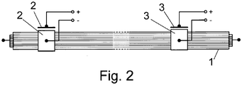
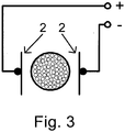
- FIG. 3 is another device with capacitive coupling in sectional view and in FIG. 4 shown in associated side view.
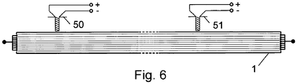
- FIG. 5 is a device with inductive coupling in sectional view and in FIG. 6 shown in associated side view.
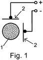
- the primary conductor 1 is shown, which is designed elongated and in which an alternating current is impressed, preferably with a frequency between 10 and 500 kHz.
- a carriage is movably arranged, which comprises a secondary conductor inductively coupled to the primary coil 1, which is a capacitor connected in parallel or in series such that the associated resonant frequency substantially the frequency of the impressed in the primary conductor alternating current equivalent.
- the strength of the alternating current can exceed 1 or even 10 amperes permanently.
- means for data transmission are provided on this carriage which can be moved along the primary conductor 1.
- These include at least those in the FIGS. 1 and 2 These are designed as rectangular metal plates whose normal direction are oriented perpendicular to each other and perpendicular to the primary conductor direction.
- the primary conductor consists of a number of stranded wires, which are each made electrically insulated from each other.
- FIG. 2 Further analogously executed coupling surfaces 3 are shown, which are connected to a voltage detecting means, whereby thus the applied voltage between the metal plates is detected.
- the coupling surfaces 3 are arranged either on a further movable carriage or stationary.
- a voltage detection means and the coupling surfaces 3 a high-frequency AC voltage source connected to then allow in this way a bidirectional data transmission.
- Different frequency bands can be used for the data transmission, preferably above 10 MHz up to 10 GHz.
- FIG. 5 is an inductive coupling of the data instead of in the FIGS. 1 and 3 shown shown capacitive coupling.
- an E-shaped ferrite core 50 is used whose center leg of the E is made much narrower than the two outer limbs of the E.
- a coupling winding is provided around the center leg, with the magnetic field lines emerging from the ferrite core 50 issuing substantially directed towards the center of the primary conductor.
- the center leg is oriented perpendicular to the direction of the primary conductor 50.
- the alternating magnetic field lines passing through the primary conductor induce electric fields, so that in turn a corresponding polarization can be generated. It is also important that in the region of the primary conductor a very inhomogeneous magnetic field is provided, that is, the magnetic field strength drops sharply in at least one direction.
- a current source and current detection means At the winding provided around the center leg, preferably instead of the according to FIGS. 1 to 4 provided voltage source and voltage detection means a current source and current detection means.
- the second ferrite core is designated by reference numeral 51.
- the geometric extent of the E is dependent on the diameter of the primary conductor 1 and the distance of the end portion of the center leg of the E from the primary conductor. 1
- a corresponding other geometry can also be selected. It is essential here that the inhomogeneous field described above can be generated within the cross section of the primary conductor.
Description
Die Erfindung betrifft eine Anordnung zur berührungslosen Energieübertragung.The invention relates to an arrangement for contactless energy transfer.
Aus der
Aus der
Aus der
Aus der
Der Erfindung liegt die Aufgabe zugrunde, eine Anordnung zur berührungslosen Energieübertragung weiterzubilden mit möglichst einfacher und kostengünstiger berührungsloser Datenübertragung.The invention has the object of developing an arrangement for contactless energy transfer with the simplest possible and cost-effective contactless data transmission.
Erfindungsgemäß wird die Aufgabe bei der Anordnung zur berührungslosen Energieübertragung nach den in Anspruch 1 angegebenen Merkmalen gelöst.According to the invention, the object is achieved in the arrangement for contactless energy transfer according to the features specified in
Wichtige Merkmale der Erfindung bei der Anordnung sind, dass die Anordnung zur berührungslosen Energieübertragung vorgesehen ist,
wobei ein langgestreckt verlegter Primärleiter vorgesehen ist,
wobei zumindest ein entlang dem Primärleiter verfahrbarer Wagen vorgesehen ist,
wobei am Wagen ein Mittel zur Datenübertragung vorgesehen ist,
wobei der Primärleiter aus gegeneinander elektrisch isoliert vorgesehenen Einzel-Litzendrähten zusammengesetzt ist,
wobei das Mittel zur Datenübertragung zumindest ein Koppelelement umfasst, welches kapazitiv an die Litzendrähte derart gekoppelt vorgesehen ist, dass Signalspannungen ein- und/oder auskoppelbar sind in die Litzendrähte,
wobei das Koppelelement zumindest zwei Koppelflächen umfasst, an die eine Spannung zum Senden von Daten anlegbar ist,
wobei die Normalenrichtungen der Koppelflächen senkrecht zueinander orientiert sind.Important features of the invention in the arrangement are that the arrangement is provided for non-contact energy transmission,
wherein an elongated laid primary conductor is provided,
wherein at least one carriage which is movable along the primary conductor is provided,
wherein on the carriage a means for data transmission is provided,
wherein the primary conductor is composed of individual stranded wires provided against each other in an electrically insulated manner,
wherein the means for data transmission comprises at least one coupling element, which is provided capacitively coupled to the stranded wires in such a way that signal voltages are input and / or decoupled into the stranded wires,
wherein the coupling element comprises at least two coupling surfaces to which a voltage for transmitting data can be applied,
wherein the normal directions of the coupling surfaces are oriented perpendicular to each other.
Von Vorteil ist dabei, dass zur Datenübertragung zwar separate Koppelmittel verwendet werden, die aber sehr kostengünstig und einfach herstellbar sind. Insbesondere ist zur Datenübertragung der für die Energieübertragung sowieso vorhandene, mit Wechselstrom von mindestens 10 kHz beaufschlagte Primärleiter verwendet. Somit ist für die Datenübertragung keine zusätzliche Leitung notwendig sondern es ist ermöglicht Signale in den Primärleiter kostengünstig und einfach einzukoppeln und weiterzutragen. Wesentliche Eigenschaft des Primärleiters ist dessen Ausführung aus Hochfrequenzlitze. Erfindungsgemäß wurde erkannt, dass ein kapazitives Einkoppeln von Signalspannungen an ein Geflecht aus Hoch einzeln gegeneinander isoliert ausgeführten Litzendrähten ausführbar ist. Bei gegeneinander nicht elektrisch isolierten Litzendrähten funktioniert diese Datenübertragung gar nicht oder zumindest stark eingeschränkt und nur bei sehr hohen Frequenzen. Unter elektrischer Isolierung wird hier eine Isolierung verstanden, die für Gleichspannungen sehr gut wirksam ist. Es ist allseits bekannt, dass bei sehr hohen Frequenzen die Isolierfähigkeit abnimmt.The advantage here is that although separate coupling means are used for data transmission, but which are very inexpensive and easy to produce. In particular, the data transmission of the existing anyway for energy transfer, with AC of at least 10 kHz applied primary conductor is used. Thus, no additional line is necessary for the data transmission but it is possible to couple signals in the primary conductor inexpensively and easily and carry on. An essential feature of the primary conductor is its design of high-frequency stranded wire. According to the invention, it has been recognized that a capacitive coupling of signal voltages to a braid of high litz wires, which are individually insulated from one another, can be carried out. In the case of stranded wires which are not electrically insulated against each other, this data transmission does not work at all or at least severely restricted and only at very high frequencies. Electrical insulation is understood to mean an insulation which is very effective for DC voltages. It is well known that at very high frequencies the insulating ability decreases.
Bei einer vorteilhaften Ausgestaltung sind die Litzendrähte jeweils an ihrem äußeren Umfang mit einer elektrischen Isolierschicht versehen. Von Vorteil ist dabei, dass mittels der kapazitiven Einkoppelung ein lokal zwischen verschiedenen Litzendrähten unterschiedliches Potential erzeugbar ist. Wenn die Litzendrähte in elektrisch leitendem Kontakt stehen würden, wären sie im Wesentlichen stets auf dem gleichen Potential. Mittels der elektrischen Isolierung ist es aber erreichbar, dass verschiedene Potentiale erreicht werden und somit Signalspannungen einkoppelbar sind, die zwischen den Litzendrähten bestehen. Sodann breiten sich die Signalspannungen in Richtung des Primärleiters aus und sind in entsprechender Weise detektierbar mittels entsprechender Koppelflächen. Da erfindungsgemäß mit Wechselspannungen und Wechselströmen, vorzugsweise über 10 kHz, gearbeitet wird, entsprechen den lokal wechselnden Potentialen der Litzendrähte gemäß Maxwellscher Gleichungen Wechselströme, weshalb bei der vorliegenden Beschreibung im Wesentlichen nicht fein unterschieden wird zwischen induzierten Strömen und diesen zugehörigen elektrischen Feldern.In an advantageous embodiment, the stranded wires are each provided at their outer periphery with an electrical insulating layer. The advantage here is that by means of the capacitive coupling a locally different potential between different stranded wires can be generated. If the stranded wires were in electrically conductive contact, they would essentially always be at the same potential. By means of the electrical insulation, however, it can be achieved that different potentials are achieved and thus signal voltages can be coupled in, which exist between the stranded wires. Then, the signal voltages propagate in the direction of the primary conductor and are in corresponding manner detectable by means of corresponding coupling surfaces. Since, according to the invention, alternating voltages and alternating currents, preferably more than 10 kHz, are used, the locally changing potentials of the stranded wires correspond to alternating currents according to Maxwell's equations, which is why in the present description there is essentially no finely differentiated between induced currents and these associated electric fields.
Es wird noch angemerkt, dass die erwähnten Ströme oder Spannungen zur Signalübertragung nur zusätzliche Anteile darstellen zu den Anteilen, welche zur Leistungsübertragung notwendig sind. Insbesondere ist hierbei die Durchschlagfestigkeit der verwendeten Isolierungen im Vergleich zur auftretenden Gesamtspannung zu berücksichtigen. Erfindungsgemäß umfasst das Koppelelement zumindest zwei Koppelflächen, an die eine Spannung anlegbar ist, insbesondere zum Senden von Daten. Von Vorteil ist dabei, dass ein elektrisches Feld ausbildbar ist, das die genannten Signalströme induziert.It is also noted that the mentioned currents or voltages for signal transmission represent only additional proportions to the proportions which are necessary for power transmission. In particular, the dielectric strength of the insulation used in comparison to the total voltage occurring in this case is taken into account. According to the invention, the coupling element comprises at least two coupling surfaces to which a voltage can be applied, in particular for transmitting data. The advantage here is that an electric field can be formed, which induces the signal currents mentioned.
Bei einer vorteilhaften Ausgestaltung umfasst das Koppelelement zumindest zwei Koppelflächen, wobei die zwischen den Koppelflächen anliegende Spannung erfassbar ist, insbesondere zum Empfangen von Daten. Von Vorteil ist dabei, dass ein Detektieren der Signalströme beziehungsweise Signalspannungen in einfacher Weise ermöglicht ist.In an advantageous embodiment, the coupling element comprises at least two coupling surfaces, wherein the voltage applied between the coupling surfaces voltage can be detected, in particular for receiving data. The advantage here is that a detection of the signal currents or signal voltages is made possible in a simple manner.
Bei einer vorteilhaften Ausgestaltung sind die Koppelflächen metallisch und/oder im Wesentlichen eben ausgeführt. Von Vorteil ist dabei, dass eine einfache kostengünstige Ausführung ausreichend ist. Erfindungsgemäß sind die Normalenrichtungen der Koppelflächen senkrecht zueinander orientiert. Bei einer vorteilhaften Ausführung stehen die Normalenrichtungen auch senkrecht zur Richtung des Primärleiters. Von Vorteil ist dabei, dass ein inhomogenes Feld im Bereich des Primärleiters entsteht und somit ein besonders gutes Signal-Rausch-Verhältnis erreichbar ist.In an advantageous embodiment, the coupling surfaces are made metallic and / or substantially planar. The advantage here is that a simple inexpensive design is sufficient. According to the invention, the normal directions of the coupling surfaces are oriented perpendicular to one another. In an advantageous embodiment, the normal directions are also perpendicular to the direction of the primary conductor. The advantage here is that an inhomogeneous field arises in the region of the primary conductor and thus a particularly good signal-to-noise ratio can be achieved.
Bei einem weiteren Bespiel sind die Normalenrichtungen der Koppelflächen parallel oder mit einem Winkel von bis zu 40° zueinander orientiert, insbesondere wobei die Normalenrichtungen auch senkrecht stehen zur Richtung des Primärleiters. Von Vorteil ist dabei, dass die Fertigung der Anordnung in einfacher Weise ausführbar ist und die zu fertigenden Winkel unkritische Wertbereiche aufweisen.In a further example, the normal directions of the coupling surfaces are oriented parallel or at an angle of up to 40 ° to each other, in particular wherein the normal directions are also perpendicular to the direction of the primary conductor. The advantage here is that the production of the arrangement can be carried out in a simple manner and have uncritical value ranges to be produced angle.
Bei einem weiteren Beispiel umfasst das Koppelement eine Wicklung, wobei das zugehörige magnetische Feld im Bereich des Primärleiters inhomogen ist. Von Vorteil ist dabei, dass ein besonders gutes Signal-Rausch-Verhältnis erreichbar ist, da der Unterschied der Werte der eingekoppelten Stromanteile und/oder Spannungsanteile in den verschiedenen Litzendrähten sehr hoch ist.In another example, the coupling element comprises a winding, wherein the associated magnetic field in the region of the primary conductor is inhomogeneous. The advantage here is that a particularly good signal-to-noise ratio is achievable, since the difference in the values of the injected current components and / or voltage components in the various stranded wires is very high.
Bei einem weiteren Beispiel umfasst das Koppelement eine Wicklung, wobei ein wesentlicher Teil des von der Wicklung erzeugten Magnetfeldes aus dem Koppelement zum Primärleiter hin austritt, insbesondere in zu einer Richtung des Primärleiters senkrechten Richtung. Von Vorteil ist dabei, dass eine induktive Einkoppelung in einfacher Weise ausführbar ist.In another example, the coupling element comprises a winding, wherein a substantial part of the magnetic field generated by the winding exits from the coupling element towards the primary conductor, in particular in a direction perpendicular to a direction of the primary conductor. The advantage here is that an inductive coupling can be carried out in a simple manner.
Bei einem weiteren Beispiel ist die Wicklung um einen Schenkel eines Ferritkerns herum vorgesehen. Insbesondere um einen Mittelschenkel eines E-förmigen Ferritkerns, insbesondere wobei die Schenkel in einer Ebene liegen, deren Normalenrichtung senkrecht zur Richtung des Primärleiters vorgesehen ist. Von Vorteil ist dabei, dass eine symmetrische Anordnung ausführbar ist und somit ein hoher Wirkungsgrad erreichbar ist, insbesondere eine zu einer die Mitte des Primärleiters enthaltenden Symmetrieebene symmetrische Anordnung, wobei eine gerade Verlegung des Primärleiters vorausgesetzt ist. Bei nicht gerader Verlegung des Primärleiters gilt der geschilderte Sachverhalt zumindest im durch die Koppelelemente überdeckten Streckenbereich des Primärleiters.In another example, the winding is provided around a leg of a ferrite core. In particular, about a center leg of an E-shaped ferrite core, in particular wherein the legs lie in a plane whose normal direction is provided perpendicular to the direction of the primary conductor. The advantage here is that a symmetrical arrangement can be executed and thus a high efficiency can be achieved, in particular a symmetrical to a symmetry plane containing the center of the primary conductor, with a straight installation of the primary conductor is assumed. In the case of non-straight laying of the primary conductor, the described situation applies at least in the route area of the primary conductor covered by the coupling elements.
Bei einer vorteilhaften Ausgestaltung umfasst ein stationär angeordnetes Mittel zur Datenübertragung ebenfalls ein entsprechendes Koppelelement, insbesondere wobei Datenübertragung zwischen einem oder mehreren Wagen sowie dem stationär angeordneten Mittel vorgesehen ist. Von Vorteil ist dabei, dass zwischen zwei zum Primärleiter beweglichen Fahrzeugen und/oder zwischen einem zum Primärleiter beweglichen Fahrzeug und einer stationär zum Primärleiter angeordneten Vorrichtung die erfindungsgemäße berührungslose Datenübertragung ermöglicht ist.In an advantageous embodiment, a stationarily arranged means for data transmission also comprises a corresponding coupling element, in particular wherein data transmission between one or more cars and the stationarily arranged means is provided. The advantage here is that between two to the primary conductor movable vehicles and / or between one to the primary conductor movable vehicle and a stationarily arranged to the primary conductor device contactless data transmission according to the invention is made possible.
Bei einer vorteilhaften Ausgestaltung ist an dem Wagen eine mit dem Primärleiter induktiv gekoppelte Sekundärwicklung zur Versorgung eines am Wagen vorgesehenen oder mit dem Wagen verbundenen oder elektrisch oder magnetisch gekoppelten Verbrauchers vorgesehen. Von Vorteil ist dabei, dass der Wagen beispielsweise einen elektrischen Antrieb aufweisen darf, mit welchem dieser Wagen, also ein Fahrzeug, und/oder eine auf dem Wagen vorgesehene Last bewegbar ist. Darüber hinaus ist auch eine stationär angeordnete Einheit aus dem Wagen beispielsweise induktiv versorgbar, wobei somit der Wagen bei Erreichen der geeigneten Position diese weitere berührungslose Energieübertragung ermöglicht.In an advantageous embodiment of the carriage is provided with a secondary conductor inductively coupled to the secondary winding for supplying a provided on the car or connected to the car or electrically or magnetically coupled consumer. The advantage here is that the car may for example have an electric drive, with which this car, so a vehicle, and / or a load provided on the car is movable. In addition, a stationarily arranged unit from the car, for example, can be supplied inductively, thus allowing the car upon reaching the appropriate position, this further non-contact power transmission.
Bei einer vorteilhaften Ausgestaltung wird in den Primärleiter ein Wechselstrom eingeprägt, insbesondere mit einer Frequenz zwischen 10 und 500 kHz, insbesondere mit über 1 oder sogar 10 Ampere. Von Vorteil ist dabei, dass
Hohe Leistungen im Bereich von Kilowatt übertragbar sind, wobei nur geringe Verluste auftreten.In an advantageous embodiment, an alternating current is impressed into the primary conductor, in particular with a frequency between 10 and 500 kHz, in particular with more than 1 or even 10 amperes. The advantage here is that
High power in the range of kilowatts are transferable, whereby only small losses occur.
Bei einer vorteilhaften Ausgestaltung ist der Sekundärwicklung eine Kapazität derart in Reihe oder parallel zugeschaltet, dass die zugehörige Resonanzfrequenz im Wesentlichen der Frequenz des in den Primärleiter eingeprägten Wechselstromes entspricht. Von Vorteil ist dabei, dass ein besonders hoher Wirkungsgrad erreichbar ist auch bei schwankendem und/oder schlechtem Kopplungsgrad.In an advantageous embodiment, the secondary winding has a capacitance connected in series or in parallel such that the associated resonant frequency essentially corresponds to the frequency of the alternating current impressed into the primary conductor. The advantage here is that a particularly high efficiency can be achieved even with fluctuating and / or poor degree of coupling.
Weitere Vorteile ergeben sich aus den Unteransprüchen.Further advantages emerge from the subclaims.
- 11
- Primärleiterprimary conductor
- 22
- Koppelflächecoupling surface
- 33
- Koppelflächecoupling surface
- 5050
- Ferritkernferrite
- 5151
- Ferritkernferrite
Die Erfindung wird nun anhand von Abbildungen näher erläutert:
- In
der Figur 1 ist eine erfindungsgemäße Vorrichtung mit kapazitiver Kopplung in Schnittansicht und inFigur 2
- In the
FIG. 1 is a device according to the invention with capacitive coupling in sectional view and inFIG. 2 shown in associated side view.
In der
In
In
Entlang diesem in einer Anlage verlegten Primärleiter 1 ist ein Wagen bewegbar angeordnet, der eine an den Primärleiter 1 induktiv gekoppelte Sekundärspule umfasst, der eine Kapazität parallel oder in Reihe derart zugeschaltet ist, dass die zugehörige Resonanzfrequenz im Wesentlichen der Frequenz des in den Primärleiter eingeprägten Wechselstromes entspricht. Die Stärke des Wechselstromes kann hierbei 1 oder sogar 10 Ampere dauerhaft übersteigen.Along this laid in a plant
An diesem entlang des Primärleiters 1 verfahrbaren Wagen sind des Weiteren Mittel zur Datenübertragung vorgesehen. Diese umfassen zumindest die in den
Anstatt rechteckförmiger Metallplatten sind auch quadratische oder abgerundete Metallplatten verwendbar.Instead of rectangular metal plates square or rounded metal plates are used.
An die beiden Metallplatten wird jeweils ein Potential einer hochfrequenten Wechselspannungsquelle angelegt und somit eine Polarisierung im Bereich des Primärleiters 1 bewirkt, der als Hochfrequenz-Litze ausgeführt ist. Dabei besteht also der Primärleiter aus einer Anzahl von Litzendrähten, die jeweils elektrisch zueinander isoliert ausgeführt sind.In each case a potential of a high-frequency AC voltage source is applied to the two metal plates and thus a polarization in the region of the
In
In der geschilderten Weise ist also eine Datenübertragung zwischen dem mit den Koppelflächen 2 verbundenen System und dem mit den Koppelflächen 3 verbundenen System ermöglicht.In the described manner, therefore, a data transmission between the system connected to the coupling surfaces 2 and the system connected to the coupling surfaces 3 system is possible.
Ebenso ist zusätzlich an den Koppelflächen 2 ein Spannungserfassungsmittel und an den Koppelflächen 3 eine hochfrequente Wechselspannungsquelle verbindbar, um dann auf diese Weise eine bidirektionale Datenübertragung zu ermöglichen.Likewise, in addition to the coupling surfaces 2, a voltage detection means and the coupling surfaces 3, a high-frequency AC voltage source connected to then allow in this way a bidirectional data transmission.
Für die Datenübertragung sind verschiedene Frequenzbänder nutzbar, vorzugsweise oberhalb 10 MHz bis zu 10 GHz.Different frequency bands can be used for the data transmission, preferably above 10 MHz up to 10 GHz.
In den
In der
Hierzu wird ein E-förmiger Ferritkern 50 verwendet, dessen Mittelschenkel des E viel schmaler ausgeführt ist als die beiden äußeren Schenkel des E.For this purpose, an
Um den Mittelschenkel herum ist eine einkoppelnde Wicklung vorgesehen, wobei die aus dem Ferritkern 50 austretenden Magnetfeldlinien im Wesentlichen auf die Mitte des Primärleiters hin gerichtet austreten. Insbesondere ist der Mittelschenkel senkrecht zur Richtung des Primärleiters 50 orientiert.A coupling winding is provided around the center leg, with the magnetic field lines emerging from the
Die durch den Primärleiter verlaufenden Wechsel-Magnetfeldlinien induzieren elektrische Felder, so dass wiederum eine entsprechende Polarisierung erzeugbar ist. Wichtig ist dabei auch, dass im Bereich des Primärleiters ein sehr inhomogenes Magnetfeld vorgesehen ist, also die Magnetfeldstärke in zumindest einer Richtung stark abfällt.The alternating magnetic field lines passing through the primary conductor induce electric fields, so that in turn a corresponding polarization can be generated. It is also important that in the region of the primary conductor a very inhomogeneous magnetic field is provided, that is, the magnetic field strength drops sharply in at least one direction.
An der um den Mittelschenkel herum vorgesehenen Wicklung sind vorzugsweise anstatt der gemäß
Ansonsten ist auch bei einer Anordnung nach
Die geometrische Ausdehnung des E ist dabei abhängig vom Durchmesser des Primärleiters 1 und dem Abstand des Endbereiches des Mittelschenkel des E vom Primärleiter 1.The geometric extent of the E is dependent on the diameter of the
Bei weiteren Beispielen ist statt eines E auch eine entsprechende andere Geometrie wählbar. Wesentlich hierbei ist, dass das oben beschriebene inhomogene Feld innerhalb des Querschnitts des Primärleiters erzeugbar ist.In further examples, instead of an E, a corresponding other geometry can also be selected. It is essential here that the inhomogeneous field described above can be generated within the cross section of the primary conductor.
Bei weiteren Beispielen sind auch statt nur zweier Koppelflächen weitere Koppelflächen beziehungsweise statt eines Ferritkerns weitere am gleichen Wagen, also Fahrzeug, vorsehbar.In further examples, instead of just two coupling surfaces, further coupling surfaces or, instead of a ferrite core, further coupling elements on the same vehicle, ie vehicle, can be provided.
Zur Datenübertragung sind auch verschiedene Frequenzbänder zusammen nutzbar, indem zwei oder mehrere verschieden frequente Signalverläufe überlagert werden. Auf Empfängerseite sind dann entsprechende Filter vorzusehen.For data transmission and various frequency bands are used together by two or more different frequency waveforms are superimposed. On the receiver side then appropriate filters are provided.
Das in dieser Schrift verwendete Wort senkrecht ist nicht als exakter Winkel von 90° zu verstehen sondern es sind auch Winkel zwischen 50° und 130° zu verstehen, also geringfügige Abweichungen von der mathematisch exakten senkrechten Richtung. Ebenso sind die Koppelflächen (2,3) vom Primärleiter aus gesehen zwar im Wesentlichen eben gestaltet, aber die ebene Ausführung erlaubt auch kleine wellenförmige Abweichungen von der idealen Ebene, wobei die zugehörige Amplitude auch bis 20% vom Abstand der Koppelfläche zur Oberfläche des Primärleiters betragen darf.The word perpendicular used in this document is not to be understood as an exact angle of 90 ° but also angles between 50 ° and 130 ° to understand, so minor deviations from the mathematically exact vertical direction. As well are the coupling surfaces (2,3) as viewed from the primary conductor, although essentially flat, but the planar design also allows small undulating deviations from the ideal plane, the associated amplitude may be up to 20% of the distance of the coupling surface to the surface of the primary conductor ,
Claims (9)
- Arrangement for contactless energy transmission,
wherein a primary conductor laid elongated is provided, wherein at least one carriage movable along the primary conductor is provided,
wherein a means for data transmission is provided on the carriage,
wherein the primary conductor is composed of single-stranded wires provided electrically insulated from one another, characterised in that
the means for data transmission comprises at least one coupling element which is provided capacitively coupled to the stranded wires in such a way that signal voltages can be coupled into and/or out of the stranded wires,
wherein the coupling element comprises at least two coupling surfaces, to which a voltage can be applied for transmitting data,
wherein the normal directions of the coupling surfaces are oriented perpendicular to one another. - Arrangement according to Claim 1,
characterised in that
the stranded wires are each provided with an electrical insulating layer at their outer periphery. - Arrangement according to at least one of the preceding claims,
characterised in that
the coupling element comprises at least two coupling surfaces, wherein the voltage applied between the coupling surfaces is detectable, in particular for receiving data. - Arrangement according to at least one of the preceding claims,
characterised in that
the coupling surfaces are of metallic and/or substantially plane design. - Arrangement according to at least one of the preceding claims,
characterised in that
the normal directions are also perpendicular to the direction of the primary conductor. - Arrangement according to at least one of the preceding claims,
characterised in that
a stationarily arranged means for data transmission likewise comprises a corresponding coupling element, in particular wherein data transmission between one or more carriages and the stationarily arranged means is provided. - Arrangement according to at least one of the preceding claims,
characterised in that
on the carriage there is provided a secondary winding, inductively coupled to the primary conductor, for supplying a load provided on the carriage or electrically or magnetically coupled to the carriage. - Arrangement according to at least one of the preceding claims,
characterised in that
an alternating current, in particular with a frequency between 10 and 500 kHz, in particular with more than 1 or even 10 amperes, is applied to the primary conductor. - Arrangement according to Claim 7,
characterised in that
a capacitance is connected in series or in parallel with the secondary winding in such a way that the associated resonant frequency corresponds substantially to the frequency of the alternating current applied to the primary conductor.
Applications Claiming Priority (2)
| Application Number | Priority Date | Filing Date | Title |
|---|---|---|---|
| DE102008059091A DE102008059091B4 (en) | 2008-11-26 | 2008-11-26 | Arrangement for contactless energy transmission |
| PCT/EP2009/008352 WO2010060593A1 (en) | 2008-11-26 | 2009-11-24 | Arrangement for noncontact energy transfer |
Publications (2)
| Publication Number | Publication Date |
|---|---|
| EP2371069A1 EP2371069A1 (en) | 2011-10-05 |
| EP2371069B1 true EP2371069B1 (en) | 2017-08-02 |
Family
ID=41611209
Family Applications (1)
| Application Number | Title | Priority Date | Filing Date |
|---|---|---|---|
| EP09775099.6A Active EP2371069B1 (en) | 2008-11-26 | 2009-11-24 | Arrangement for noncontact energy transfer |
Country Status (3)
| Country | Link |
|---|---|
| EP (1) | EP2371069B1 (en) |
| DE (2) | DE102008059091B4 (en) |
| WO (1) | WO2010060593A1 (en) |
Families Citing this family (3)
| Publication number | Priority date | Publication date | Assignee | Title |
|---|---|---|---|---|
| DE102010008858B4 (en) | 2010-02-22 | 2013-01-17 | Sew-Eurodrive Gmbh & Co. Kg | Arrangement for contactless energy transmission |
| DE102010009073B4 (en) | 2010-02-23 | 2013-01-17 | Sew-Eurodrive Gmbh & Co. Kg | Arrangement for contactless energy transmission |
| US10692646B2 (en) | 2017-07-19 | 2020-06-23 | Toyota Motor Engineering & Manufacturing North America, Inc. | Single litz wire transformers |
Citations (2)
| Publication number | Priority date | Publication date | Assignee | Title |
|---|---|---|---|---|
| DE102005008555A1 (en) * | 2005-02-23 | 2006-08-24 | Sew-Eurodrive Gmbh & Co. Kg | Vehicle position determining system, has position determining unit, finding position of vehicle, having unit to determine amplitude phases of alternating current parts, and secondary-sided electronic circuit with resonance circuit |
| WO2008058627A2 (en) * | 2006-11-17 | 2008-05-22 | Sew-Eurodrive Gmbh & Co. Kg | Machine or installation and method |
Family Cites Families (7)
| Publication number | Priority date | Publication date | Assignee | Title |
|---|---|---|---|---|
| US5293308A (en) * | 1991-03-26 | 1994-03-08 | Auckland Uniservices Limited | Inductive power distribution system |
| DE4446779C2 (en) * | 1994-12-24 | 1996-12-19 | Daimler Benz Ag | Arrangement for the contactless inductive transmission of electrical power |
| WO1999050806A1 (en) * | 1998-04-01 | 1999-10-07 | Barret Massey Cunningham | Signalling system based on inductive power/signal transfer |
| WO2004090918A1 (en) * | 2003-04-07 | 2004-10-21 | Auckland Uniservices Limited | Communications for inductive power systems |
| DE102004031580B4 (en) * | 2004-06-29 | 2007-02-01 | Sew-Eurodrive Gmbh & Co. Kg | Arrangement for non-contact inductive energy transmission to movable devices |
| DE102007051917B4 (en) * | 2006-11-27 | 2017-03-30 | Sew-Eurodrive Gmbh & Co Kg | Actuator, in particular linear drive, and system or machine |
| DE102007059046B3 (en) * | 2007-12-06 | 2009-04-30 | Sew-Eurodrive Gmbh & Co. Kg | Contactless energy transmission device for data communication, has data transmission device attached or coupled to primary conductor, and electrically conductive coupling surface with primary conductor forming capacitive coupling element |
-
2008
- 2008-11-26 DE DE102008059091A patent/DE102008059091B4/en active Active
- 2008-11-26 DE DE102008064673A patent/DE102008064673B4/en active Active
-
2009
- 2009-11-24 EP EP09775099.6A patent/EP2371069B1/en active Active
- 2009-11-24 WO PCT/EP2009/008352 patent/WO2010060593A1/en active Application Filing
Patent Citations (2)
| Publication number | Priority date | Publication date | Assignee | Title |
|---|---|---|---|---|
| DE102005008555A1 (en) * | 2005-02-23 | 2006-08-24 | Sew-Eurodrive Gmbh & Co. Kg | Vehicle position determining system, has position determining unit, finding position of vehicle, having unit to determine amplitude phases of alternating current parts, and secondary-sided electronic circuit with resonance circuit |
| WO2008058627A2 (en) * | 2006-11-17 | 2008-05-22 | Sew-Eurodrive Gmbh & Co. Kg | Machine or installation and method |
Also Published As
| Publication number | Publication date |
|---|---|
| DE102008064673B4 (en) | 2013-05-29 |
| DE102008064673A1 (en) | 2010-09-09 |
| WO2010060593A1 (en) | 2010-06-03 |
| DE102008059091A1 (en) | 2010-06-02 |
| DE102008059091B4 (en) | 2010-09-30 |
| EP2371069A1 (en) | 2011-10-05 |
Similar Documents
| Publication | Publication Date | Title |
|---|---|---|
| EP2225814B1 (en) | Device for non-contact energy transmission and arrangement with electric loads | |
| DE102006025460B4 (en) | Plant with a primary conductor system | |
| DE10344144B4 (en) | Arrangement for non-contact inductive transmission of electrical power | |
| EP1855909B1 (en) | System and method for determining a position | |
| EP2371069B1 (en) | Arrangement for noncontact energy transfer | |
| EP2673157B1 (en) | Apparatus for power transmission and for inductive communication | |
| DE102007023343A1 (en) | Transmitter head for contactless energy transmission system, has condensers and winding arranged in inner side of housing and separated by ferrite parts, where condensers and secondary coil are arranged in same or overlapping axial areas | |
| EP2700140B1 (en) | System for the inductive energy transmission to an electrical load | |
| DE102007024293B4 (en) | System with primary conductor system and movably arranged device | |
| EP2540003B1 (en) | Assembly for non-contact energy transfer | |
| DE102006025461B4 (en) | Transmitter head for a system for contactless energy transmission and system with a transmitter head | |
| DE19957621A1 (en) | Arrangement for the transmission of electrical signals between moving parts with a reduced number of paths | |
| EP2540004B1 (en) | Arrangement for transmitting energy without contact | |
| DE102006026773B4 (en) | investment | |
| EP3323134B1 (en) | Arrangement for inductive energy transmission from a primary conductor system to a vehicle having a secondary winding | |
| EP3544707B1 (en) | Model car racetrack | |
| WO2021032313A1 (en) | System for contactless transmission of electrical power from a primary conductor to a winding |
Legal Events
| Date | Code | Title | Description |
|---|---|---|---|
| PUAI | Public reference made under article 153(3) epc to a published international application that has entered the european phase |
Free format text: ORIGINAL CODE: 0009012 |
|
| 17P | Request for examination filed |
Effective date: 20110627 |
|
| AK | Designated contracting states |
Kind code of ref document: A1 Designated state(s): AT BE BG CH CY CZ DE DK EE ES FI FR GB GR HR HU IE IS IT LI LT LU LV MC MK MT NL NO PL PT RO SE SI SK SM TR |
|
| DAX | Request for extension of the european patent (deleted) | ||
| GRAP | Despatch of communication of intention to grant a patent |
Free format text: ORIGINAL CODE: EPIDOSNIGR1 |
|
| INTG | Intention to grant announced |
Effective date: 20170324 |
|
| GRAS | Grant fee paid |
Free format text: ORIGINAL CODE: EPIDOSNIGR3 |
|
| GRAA | (expected) grant |
Free format text: ORIGINAL CODE: 0009210 |
|
| AK | Designated contracting states |
Kind code of ref document: B1 Designated state(s): AT BE BG CH CY CZ DE DK EE ES FI FR GB GR HR HU IE IS IT LI LT LU LV MC MK MT NL NO PL PT RO SE SI SK SM TR |
|
| REG | Reference to a national code |
Ref country code: GB Ref legal event code: FG4D Free format text: NOT ENGLISH |
|
| REG | Reference to a national code |
Ref country code: CH Ref legal event code: EP Ref country code: AT Ref legal event code: REF Ref document number: 915504 Country of ref document: AT Kind code of ref document: T Effective date: 20170815 |
|
| REG | Reference to a national code |
Ref country code: IE Ref legal event code: FG4D Free format text: LANGUAGE OF EP DOCUMENT: GERMAN |
|
| REG | Reference to a national code |
Ref country code: DE Ref legal event code: R096 Ref document number: 502009014225 Country of ref document: DE |
|
| REG | Reference to a national code |
Ref country code: FR Ref legal event code: PLFP Year of fee payment: 9 |
|
| REG | Reference to a national code |
Ref country code: NL Ref legal event code: MP Effective date: 20170802 |
|
| REG | Reference to a national code |
Ref country code: LT Ref legal event code: MG4D |
|
| PG25 | Lapsed in a contracting state [announced via postgrant information from national office to epo] |
Ref country code: NL Free format text: LAPSE BECAUSE OF FAILURE TO SUBMIT A TRANSLATION OF THE DESCRIPTION OR TO PAY THE FEE WITHIN THE PRESCRIBED TIME-LIMIT Effective date: 20170802 Ref country code: LT Free format text: LAPSE BECAUSE OF FAILURE TO SUBMIT A TRANSLATION OF THE DESCRIPTION OR TO PAY THE FEE WITHIN THE PRESCRIBED TIME-LIMIT Effective date: 20170802 Ref country code: HR Free format text: LAPSE BECAUSE OF FAILURE TO SUBMIT A TRANSLATION OF THE DESCRIPTION OR TO PAY THE FEE WITHIN THE PRESCRIBED TIME-LIMIT Effective date: 20170802 Ref country code: SE Free format text: LAPSE BECAUSE OF FAILURE TO SUBMIT A TRANSLATION OF THE DESCRIPTION OR TO PAY THE FEE WITHIN THE PRESCRIBED TIME-LIMIT Effective date: 20170802 Ref country code: NO Free format text: LAPSE BECAUSE OF FAILURE TO SUBMIT A TRANSLATION OF THE DESCRIPTION OR TO PAY THE FEE WITHIN THE PRESCRIBED TIME-LIMIT Effective date: 20171102 Ref country code: FI Free format text: LAPSE BECAUSE OF FAILURE TO SUBMIT A TRANSLATION OF THE DESCRIPTION OR TO PAY THE FEE WITHIN THE PRESCRIBED TIME-LIMIT Effective date: 20170802 |
|
| PG25 | Lapsed in a contracting state [announced via postgrant information from national office to epo] |
Ref country code: LV Free format text: LAPSE BECAUSE OF FAILURE TO SUBMIT A TRANSLATION OF THE DESCRIPTION OR TO PAY THE FEE WITHIN THE PRESCRIBED TIME-LIMIT Effective date: 20170802 Ref country code: ES Free format text: LAPSE BECAUSE OF FAILURE TO SUBMIT A TRANSLATION OF THE DESCRIPTION OR TO PAY THE FEE WITHIN THE PRESCRIBED TIME-LIMIT Effective date: 20170802 Ref country code: GR Free format text: LAPSE BECAUSE OF FAILURE TO SUBMIT A TRANSLATION OF THE DESCRIPTION OR TO PAY THE FEE WITHIN THE PRESCRIBED TIME-LIMIT Effective date: 20171103 Ref country code: BG Free format text: LAPSE BECAUSE OF FAILURE TO SUBMIT A TRANSLATION OF THE DESCRIPTION OR TO PAY THE FEE WITHIN THE PRESCRIBED TIME-LIMIT Effective date: 20171102 Ref country code: PL Free format text: LAPSE BECAUSE OF FAILURE TO SUBMIT A TRANSLATION OF THE DESCRIPTION OR TO PAY THE FEE WITHIN THE PRESCRIBED TIME-LIMIT Effective date: 20170802 Ref country code: IS Free format text: LAPSE BECAUSE OF FAILURE TO SUBMIT A TRANSLATION OF THE DESCRIPTION OR TO PAY THE FEE WITHIN THE PRESCRIBED TIME-LIMIT Effective date: 20171202 |
|
| PG25 | Lapsed in a contracting state [announced via postgrant information from national office to epo] |
Ref country code: DK Free format text: LAPSE BECAUSE OF FAILURE TO SUBMIT A TRANSLATION OF THE DESCRIPTION OR TO PAY THE FEE WITHIN THE PRESCRIBED TIME-LIMIT Effective date: 20170802 Ref country code: RO Free format text: LAPSE BECAUSE OF FAILURE TO SUBMIT A TRANSLATION OF THE DESCRIPTION OR TO PAY THE FEE WITHIN THE PRESCRIBED TIME-LIMIT Effective date: 20170802 Ref country code: CZ Free format text: LAPSE BECAUSE OF FAILURE TO SUBMIT A TRANSLATION OF THE DESCRIPTION OR TO PAY THE FEE WITHIN THE PRESCRIBED TIME-LIMIT Effective date: 20170802 |
|
| REG | Reference to a national code |
Ref country code: DE Ref legal event code: R097 Ref document number: 502009014225 Country of ref document: DE |
|
| PG25 | Lapsed in a contracting state [announced via postgrant information from national office to epo] |
Ref country code: SK Free format text: LAPSE BECAUSE OF FAILURE TO SUBMIT A TRANSLATION OF THE DESCRIPTION OR TO PAY THE FEE WITHIN THE PRESCRIBED TIME-LIMIT Effective date: 20170802 Ref country code: SM Free format text: LAPSE BECAUSE OF FAILURE TO SUBMIT A TRANSLATION OF THE DESCRIPTION OR TO PAY THE FEE WITHIN THE PRESCRIBED TIME-LIMIT Effective date: 20170802 Ref country code: EE Free format text: LAPSE BECAUSE OF FAILURE TO SUBMIT A TRANSLATION OF THE DESCRIPTION OR TO PAY THE FEE WITHIN THE PRESCRIBED TIME-LIMIT Effective date: 20170802 Ref country code: IT Free format text: LAPSE BECAUSE OF FAILURE TO SUBMIT A TRANSLATION OF THE DESCRIPTION OR TO PAY THE FEE WITHIN THE PRESCRIBED TIME-LIMIT Effective date: 20170802 |
|
| PLBE | No opposition filed within time limit |
Free format text: ORIGINAL CODE: 0009261 |
|
| STAA | Information on the status of an ep patent application or granted ep patent |
Free format text: STATUS: NO OPPOSITION FILED WITHIN TIME LIMIT |
|
| PG25 | Lapsed in a contracting state [announced via postgrant information from national office to epo] |
Ref country code: MC Free format text: LAPSE BECAUSE OF FAILURE TO SUBMIT A TRANSLATION OF THE DESCRIPTION OR TO PAY THE FEE WITHIN THE PRESCRIBED TIME-LIMIT Effective date: 20170802 |
|
| 26N | No opposition filed |
Effective date: 20180503 |
|
| PG25 | Lapsed in a contracting state [announced via postgrant information from national office to epo] |
Ref country code: LI Free format text: LAPSE BECAUSE OF NON-PAYMENT OF DUE FEES Effective date: 20171130 Ref country code: CH Free format text: LAPSE BECAUSE OF NON-PAYMENT OF DUE FEES Effective date: 20171130 |
|
| PG25 | Lapsed in a contracting state [announced via postgrant information from national office to epo] |
Ref country code: SI Free format text: LAPSE BECAUSE OF FAILURE TO SUBMIT A TRANSLATION OF THE DESCRIPTION OR TO PAY THE FEE WITHIN THE PRESCRIBED TIME-LIMIT Effective date: 20170802 Ref country code: LU Free format text: LAPSE BECAUSE OF NON-PAYMENT OF DUE FEES Effective date: 20171124 |
|
| REG | Reference to a national code |
Ref country code: BE Ref legal event code: MM Effective date: 20171130 |
|
| REG | Reference to a national code |
Ref country code: IE Ref legal event code: MM4A |
|
| PG25 | Lapsed in a contracting state [announced via postgrant information from national office to epo] |
Ref country code: MT Free format text: LAPSE BECAUSE OF FAILURE TO SUBMIT A TRANSLATION OF THE DESCRIPTION OR TO PAY THE FEE WITHIN THE PRESCRIBED TIME-LIMIT Effective date: 20170802 |
|
| REG | Reference to a national code |
Ref country code: FR Ref legal event code: PLFP Year of fee payment: 10 |
|
| PG25 | Lapsed in a contracting state [announced via postgrant information from national office to epo] |
Ref country code: IE Free format text: LAPSE BECAUSE OF NON-PAYMENT OF DUE FEES Effective date: 20171124 |
|
| PG25 | Lapsed in a contracting state [announced via postgrant information from national office to epo] |
Ref country code: BE Free format text: LAPSE BECAUSE OF NON-PAYMENT OF DUE FEES Effective date: 20171130 |
|
| REG | Reference to a national code |
Ref country code: AT Ref legal event code: MM01 Ref document number: 915504 Country of ref document: AT Kind code of ref document: T Effective date: 20171124 |
|
| PG25 | Lapsed in a contracting state [announced via postgrant information from national office to epo] |
Ref country code: AT Free format text: LAPSE BECAUSE OF NON-PAYMENT OF DUE FEES Effective date: 20171124 |
|
| PG25 | Lapsed in a contracting state [announced via postgrant information from national office to epo] |
Ref country code: HU Free format text: LAPSE BECAUSE OF FAILURE TO SUBMIT A TRANSLATION OF THE DESCRIPTION OR TO PAY THE FEE WITHIN THE PRESCRIBED TIME-LIMIT; INVALID AB INITIO Effective date: 20091124 |
|
| PG25 | Lapsed in a contracting state [announced via postgrant information from national office to epo] |
Ref country code: CY Free format text: LAPSE BECAUSE OF NON-PAYMENT OF DUE FEES Effective date: 20170802 |
|
| PG25 | Lapsed in a contracting state [announced via postgrant information from national office to epo] |
Ref country code: MK Free format text: LAPSE BECAUSE OF FAILURE TO SUBMIT A TRANSLATION OF THE DESCRIPTION OR TO PAY THE FEE WITHIN THE PRESCRIBED TIME-LIMIT Effective date: 20170802 |
|
| PG25 | Lapsed in a contracting state [announced via postgrant information from national office to epo] |
Ref country code: TR Free format text: LAPSE BECAUSE OF FAILURE TO SUBMIT A TRANSLATION OF THE DESCRIPTION OR TO PAY THE FEE WITHIN THE PRESCRIBED TIME-LIMIT Effective date: 20170802 |
|
| PG25 | Lapsed in a contracting state [announced via postgrant information from national office to epo] |
Ref country code: PT Free format text: LAPSE BECAUSE OF FAILURE TO SUBMIT A TRANSLATION OF THE DESCRIPTION OR TO PAY THE FEE WITHIN THE PRESCRIBED TIME-LIMIT Effective date: 20170802 |
|
| PGFP | Annual fee paid to national office [announced via postgrant information from national office to epo] |
Ref country code: FR Payment date: 20230929 Year of fee payment: 15 |
|
| PGFP | Annual fee paid to national office [announced via postgrant information from national office to epo] |
Ref country code: GB Payment date: 20231006 Year of fee payment: 15 |
|
| PGFP | Annual fee paid to national office [announced via postgrant information from national office to epo] |
Ref country code: DE Payment date: 20231130 Year of fee payment: 15 |