US10692646B2 - Single litz wire transformers - Google Patents
Single litz wire transformers Download PDFInfo
- Publication number
- US10692646B2 US10692646B2 US15/653,635 US201715653635A US10692646B2 US 10692646 B2 US10692646 B2 US 10692646B2 US 201715653635 A US201715653635 A US 201715653635A US 10692646 B2 US10692646 B2 US 10692646B2
- Authority
- US
- United States
- Prior art keywords
- transformer
- terminal
- litz wire
- group
- individual strands
- Prior art date
- Legal status (The legal status is an assumption and is not a legal conclusion. Google has not performed a legal analysis and makes no representation as to the accuracy of the status listed.)
- Expired - Fee Related, expires
Links
- 238000004804 winding Methods 0.000 claims abstract description 90
- 239000004020 conductor Substances 0.000 claims abstract description 30
- 239000000463 material Substances 0.000 claims description 16
- 230000008878 coupling Effects 0.000 claims description 6
- 238000010168 coupling process Methods 0.000 claims description 6
- 238000005859 coupling reaction Methods 0.000 claims description 6
- 229910000976 Electrical steel Inorganic materials 0.000 claims description 3
- 230000003247 decreasing effect Effects 0.000 claims description 2
- 238000000034 method Methods 0.000 abstract description 4
- 239000011162 core material Substances 0.000 description 49
- 230000007423 decrease Effects 0.000 description 6
- 230000002500 effect on skin Effects 0.000 description 6
- 238000010586 diagram Methods 0.000 description 3
- 230000005672 electromagnetic field Effects 0.000 description 3
- 230000004907 flux Effects 0.000 description 3
- XEEYBQQBJWHFJM-UHFFFAOYSA-N Iron Chemical compound [Fe] XEEYBQQBJWHFJM-UHFFFAOYSA-N 0.000 description 2
- 229910001182 Mo alloy Inorganic materials 0.000 description 2
- 239000000919 ceramic Substances 0.000 description 2
- 238000005229 chemical vapour deposition Methods 0.000 description 2
- 238000010276 construction Methods 0.000 description 2
- 230000000694 effects Effects 0.000 description 2
- 238000012986 modification Methods 0.000 description 2
- 230000004048 modification Effects 0.000 description 2
- 239000000615 nonconductor Substances 0.000 description 2
- 238000005240 physical vapour deposition Methods 0.000 description 2
- 239000007787 solid Substances 0.000 description 2
- RYGMFSIKBFXOCR-UHFFFAOYSA-N Copper Chemical compound [Cu] RYGMFSIKBFXOCR-UHFFFAOYSA-N 0.000 description 1
- 239000004593 Epoxy Substances 0.000 description 1
- 229910001030 Iron–nickel alloy Inorganic materials 0.000 description 1
- 229910001289 Manganese-zinc ferrite Inorganic materials 0.000 description 1
- 229910001053 Nickel-zinc ferrite Inorganic materials 0.000 description 1
- 229910000831 Steel Inorganic materials 0.000 description 1
- JIYIUPFAJUGHNL-UHFFFAOYSA-N [O--].[O--].[O--].[O--].[O--].[O--].[O--].[O--].[O--].[O--].[O--].[O--].[O--].[O--].[O--].[O--].[O--].[O--].[O--].[O--].[Mn++].[Mn++].[Mn++].[Fe+3].[Fe+3].[Fe+3].[Fe+3].[Fe+3].[Fe+3].[Fe+3].[Fe+3].[Fe+3].[Fe+3].[Zn++].[Zn++] Chemical compound [O--].[O--].[O--].[O--].[O--].[O--].[O--].[O--].[O--].[O--].[O--].[O--].[O--].[O--].[O--].[O--].[O--].[O--].[O--].[O--].[Mn++].[Mn++].[Mn++].[Fe+3].[Fe+3].[Fe+3].[Fe+3].[Fe+3].[Fe+3].[Fe+3].[Fe+3].[Fe+3].[Fe+3].[Zn++].[Zn++] JIYIUPFAJUGHNL-UHFFFAOYSA-N 0.000 description 1
- 239000000853 adhesive Substances 0.000 description 1
- 230000001070 adhesive effect Effects 0.000 description 1
- 239000000956 alloy Substances 0.000 description 1
- 239000011324 bead Substances 0.000 description 1
- 238000006243 chemical reaction Methods 0.000 description 1
- WYDVQMAEAOAAAJ-UHFFFAOYSA-N chromium copper iron nickel Chemical compound [Fe][Cr][Cu][Ni] WYDVQMAEAOAAAJ-UHFFFAOYSA-N 0.000 description 1
- 239000011248 coating agent Substances 0.000 description 1
- 238000000576 coating method Methods 0.000 description 1
- 229910052802 copper Inorganic materials 0.000 description 1
- 239000010949 copper Substances 0.000 description 1
- JMGBWTNUFIOURV-UHFFFAOYSA-N copper iron molybdenum nickel Chemical compound [Mo].[Cu].[Fe].[Ni] JMGBWTNUFIOURV-UHFFFAOYSA-N 0.000 description 1
- 230000001419 dependent effect Effects 0.000 description 1
- 239000003989 dielectric material Substances 0.000 description 1
- 230000005674 electromagnetic induction Effects 0.000 description 1
- 239000008393 encapsulating agent Substances 0.000 description 1
- 239000011888 foil Substances 0.000 description 1
- 229910052742 iron Inorganic materials 0.000 description 1
- VAWNDNOTGRTLLU-UHFFFAOYSA-N iron molybdenum nickel Chemical compound [Fe].[Ni].[Mo] VAWNDNOTGRTLLU-UHFFFAOYSA-N 0.000 description 1
- 238000002955 isolation Methods 0.000 description 1
- 239000000696 magnetic material Substances 0.000 description 1
- 229910052751 metal Inorganic materials 0.000 description 1
- 239000002184 metal Substances 0.000 description 1
- 229910001092 metal group alloy Inorganic materials 0.000 description 1
- 229910000595 mu-metal Inorganic materials 0.000 description 1
- 229910000889 permalloy Inorganic materials 0.000 description 1
- 230000035699 permeability Effects 0.000 description 1
- 229920000052 poly(p-xylylene) Polymers 0.000 description 1
- 229920000642 polymer Polymers 0.000 description 1
- 239000012255 powdered metal Substances 0.000 description 1
- 239000011347 resin Substances 0.000 description 1
- 229920005989 resin Polymers 0.000 description 1
- 239000010959 steel Substances 0.000 description 1
- 229910000815 supermalloy Inorganic materials 0.000 description 1
- 230000001131 transforming effect Effects 0.000 description 1
- 238000009941 weaving Methods 0.000 description 1
- 229910000859 α-Fe Inorganic materials 0.000 description 1
Images


Classifications
-
- H—ELECTRICITY
- H01—ELECTRIC ELEMENTS
- H01F—MAGNETS; INDUCTANCES; TRANSFORMERS; SELECTION OF MATERIALS FOR THEIR MAGNETIC PROPERTIES
- H01F27/00—Details of transformers or inductances, in general
- H01F27/28—Coils; Windings; Conductive connections
- H01F27/32—Insulating of coils, windings, or parts thereof
- H01F27/324—Insulation between coil and core, between different winding sections, around the coil; Other insulation structures
-
- H—ELECTRICITY
- H01—ELECTRIC ELEMENTS
- H01F—MAGNETS; INDUCTANCES; TRANSFORMERS; SELECTION OF MATERIALS FOR THEIR MAGNETIC PROPERTIES
- H01F27/00—Details of transformers or inductances, in general
- H01F27/28—Coils; Windings; Conductive connections
- H01F27/2823—Wires
-
- H—ELECTRICITY
- H01—ELECTRIC ELEMENTS
- H01F—MAGNETS; INDUCTANCES; TRANSFORMERS; SELECTION OF MATERIALS FOR THEIR MAGNETIC PROPERTIES
- H01F17/00—Fixed inductances of the signal type
- H01F17/04—Fixed inductances of the signal type with magnetic core
- H01F17/06—Fixed inductances of the signal type with magnetic core with core substantially closed in itself, e.g. toroid
- H01F17/062—Toroidal core with turns of coil around it
-
- H—ELECTRICITY
- H01—ELECTRIC ELEMENTS
- H01F—MAGNETS; INDUCTANCES; TRANSFORMERS; SELECTION OF MATERIALS FOR THEIR MAGNETIC PROPERTIES
- H01F27/00—Details of transformers or inductances, in general
- H01F27/28—Coils; Windings; Conductive connections
- H01F27/30—Fastening or clamping coils, windings, or parts thereof together; Fastening or mounting coils or windings on core, casing, or other support
- H01F27/306—Fastening or mounting coils or windings on core, casing or other support
-
- H—ELECTRICITY
- H01—ELECTRIC ELEMENTS
- H01F—MAGNETS; INDUCTANCES; TRANSFORMERS; SELECTION OF MATERIALS FOR THEIR MAGNETIC PROPERTIES
- H01F41/00—Apparatus or processes specially adapted for manufacturing or assembling magnets, inductances or transformers; Apparatus or processes specially adapted for manufacturing materials characterised by their magnetic properties
- H01F41/02—Apparatus or processes specially adapted for manufacturing or assembling magnets, inductances or transformers; Apparatus or processes specially adapted for manufacturing materials characterised by their magnetic properties for manufacturing cores, coils, or magnets
- H01F41/04—Apparatus or processes specially adapted for manufacturing or assembling magnets, inductances or transformers; Apparatus or processes specially adapted for manufacturing materials characterised by their magnetic properties for manufacturing cores, coils, or magnets for manufacturing coils
- H01F41/06—Coil winding
- H01F41/064—Winding non-flat conductive wires, e.g. rods, cables or cords
- H01F41/069—Winding two or more wires, e.g. bifilar winding
- H01F41/07—Twisting
-
- H—ELECTRICITY
- H01—ELECTRIC ELEMENTS
- H01F—MAGNETS; INDUCTANCES; TRANSFORMERS; SELECTION OF MATERIALS FOR THEIR MAGNETIC PROPERTIES
- H01F41/00—Apparatus or processes specially adapted for manufacturing or assembling magnets, inductances or transformers; Apparatus or processes specially adapted for manufacturing materials characterised by their magnetic properties
- H01F41/02—Apparatus or processes specially adapted for manufacturing or assembling magnets, inductances or transformers; Apparatus or processes specially adapted for manufacturing materials characterised by their magnetic properties for manufacturing cores, coils, or magnets
- H01F41/04—Apparatus or processes specially adapted for manufacturing or assembling magnets, inductances or transformers; Apparatus or processes specially adapted for manufacturing materials characterised by their magnetic properties for manufacturing cores, coils, or magnets for manufacturing coils
- H01F41/06—Coil winding
- H01F41/08—Winding conductors onto closed formers or cores, e.g. threading conductors through toroidal cores
-
- H—ELECTRICITY
- H01—ELECTRIC ELEMENTS
- H01B—CABLES; CONDUCTORS; INSULATORS; SELECTION OF MATERIALS FOR THEIR CONDUCTIVE, INSULATING OR DIELECTRIC PROPERTIES
- H01B7/00—Insulated conductors or cables characterised by their form
- H01B7/30—Insulated conductors or cables characterised by their form with arrangements for reducing conductor losses when carrying alternating current, e.g. due to skin effect
-
- H—ELECTRICITY
- H01—ELECTRIC ELEMENTS
- H01R—ELECTRICALLY-CONDUCTIVE CONNECTIONS; STRUCTURAL ASSOCIATIONS OF A PLURALITY OF MUTUALLY-INSULATED ELECTRICAL CONNECTING ELEMENTS; COUPLING DEVICES; CURRENT COLLECTORS
- H01R4/00—Electrically-conductive connections between two or more conductive members in direct contact, i.e. touching one another; Means for effecting or maintaining such contact; Electrically-conductive connections having two or more spaced connecting locations for conductors and using contact members penetrating insulation
- H01R4/10—Electrically-conductive connections between two or more conductive members in direct contact, i.e. touching one another; Means for effecting or maintaining such contact; Electrically-conductive connections having two or more spaced connecting locations for conductors and using contact members penetrating insulation effected solely by twisting, wrapping, bending, crimping, or other permanent deformation
Definitions
- Embodiments described herein generally relate to electrical transformers and, more specifically, to electrical transformers having a plurality of windings in a single Litz wire.
- Electrical transformers are widely used for a variety of purposes, such as to transmit alternating current (AC) power between circuits without electrical contact between the circuits.
- AC alternating current
- leakage of magnetic linkage between windings can cause loss in power and can generate excessive electromagnetic interference (EMI).
- EMI electromagnetic interference
- Litz wire which is a wire that includes a plurality of individual strands of conductive material that are braided, stranded, or woven together into a bundled cable-like structure, may be used for the various windings of an electrical transforming.
- transformers that utilize Litz wire for windings generally use a single Litz wire for each winding, which is inefficient and costly, as a plurality of Litz wires must be used for a plurality of windings.
- a transformer in an embodiment, includes a core and a single Litz wire having a plurality of individual strands of conductive material.
- the plurality of individual strands of conductive material are separated into a plurality of groups, each one of the plurality of groups being a winding of the transformer such that the transformer includes a plurality of windings.
- a transformer in another embodiment, includes a toroidal core and a single Litz wire wrapped around at least a portion of the toroidal core.
- the single Litz wire includes a plurality of individual strands of conductive material.
- the plurality of individual strands of conductive material is arranged into a plurality of windings such that each one of the plurality of windings includes one or more of the plurality of individual strands.
- a system in yet another embodiment, includes a transformer.
- the transformer includes a core and a single Litz wire wrapped around at least a portion of the toroidal core.
- the single Litz wire includes a plurality of individual strands of conductive material.
- the plurality of individual strands of conductive material is arranged into a plurality of windings such that each one of the plurality of windings comprises one or more of the plurality of individual strands.
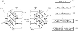
- FIG. 1A depicts a perspective view of an illustrative transformer having a single Litz wire according to one or more embodiments shown and described herein;
- FIG. 1B depicts the illustrative transformer of FIG. 1A , showing at least a portion of the Litz wire being separated into a plurality of groups of individual strands according to one or more embodiments shown and described herein;
- FIG. 2 depicts a perspective view of an illustrative Litz wire having a plurality of individual strands of conductive material according to one or more embodiments shown and described herein;
- FIG. 3 schematically depicts an electrical diagram of an illustrative transformer coupled to a plurality of terminal pairs according to one or more embodiments shown and described herein;
- FIG. 4 depicts a flow diagram of an illustrative method of providing a transformer having windings constructed of a single Litz wire according to one or more embodiments shown and described herein.
- Embodiments disclosed herein include transformers having windings made from a single Litz wire, as well as systems including such transformers and methods of providing such transformers.
- the various individual strands in a single Litz wire are grouped into a plurality of strand groups, where each strand group is coupled between a pair of terminals.
- a single Litz wire can be coupled to at least two pairs of terminals. Because the individual strands are in close proximity to one another and are electrically isolated from one another, they can increase coupling by reducing leakage inductance between windings and/or decrease conduction loss by reducing AC resistance. As a result, the transformer operates more efficiently, is less likely to be damaged due to conduction loss, but does not add extra bulk or construction costs that would occur with additional wires and/or additional shielding in wires.
- a “Litz wire” refers to a wire that includes a plurality of individual strands of conductive material that are braided, stranded, or woven together into a bundled cable-like structure that is covered with an outer jacket.
- Each of the individual strands in the Litz wire is constructed of an electrically conductive material.
- each of the individual strands is electrically insulated from the other individual strands by an electrical insulator (i.e., each strand is coated with an electrical insulator material) that is separate from the outer jacket.
- the braided, stranded, or woven features of the individual strands may be in a weaving or twisting pattern such that the individual strands are located on an exterior of the bundle for a length of the Litz wire (where the electromagnetic field changes are weakest and the strands exhibit low resistance), and are located on an interior of the bundle for a length of the Litz wire (where the electromagnetic field changes are the strongest and the strands exhibit low resistance).
- a current applied to the Litz wire is distributed equally among every strand within the Litz wire that contacts the source of the current. This allows the interior of the Litz wire to contribute to the overall conductivity of the bundle.
- the magnetic fields generated by current flowing through the individual strands of the Litz wire are in directions such that they have a reduced tendency to generate an opposing electromagnetic field in the other strands.
- the skin effect the tendency of an alternating electric current to become distributed within a conductor such that the current density is largest near the surface of the conductor and decreases with greater depths in the conductor
- the ratio of distributed inductance to distributed resistance is increased, relative to a solid conductor, resulting in a higher Q factor at these frequencies.
- a “single Litz wire” refers to one Litz wire having a plurality of individual strands, as described above.
- the single Litz wire is not limited by this disclosure with respect to length. As such, the single Litz wire may be any length.
- the number of individual strands located within the single Litz wire is not limited by this disclosure. That is, the single Litz wire may include at least two individual strands bundled together.
- a “skin effect” is a tendency of a current to become distributed within an electrical current conductor such that the current density is largest near the surface of the conductor and decreases with grater depths in the conductor. That is, the electric current flows primarily at the “skin” of the electrical current conductor between the outer surface and a particular level called the skin depth.
- the skin effect causes an effective resistance of the electrical current conductor to increase at higher frequencies where the skin depth is smaller, thus reducing the effective cross-section of the electrical current conductor.
- the skin effect is due to opposing eddy currents induced by the changing magnetic field resulting from the current. At 60 Hertz (Hz) in copper, the skin depth is about 8.5 mm. At higher frequencies, the skin depth becomes smaller. Increased current resistance due to the skin effect can be mitigated using Litz wire.
- a “proximity effect” is the result of current flowing through one or more nearby conductors, such as within a closely wound coil of wire, which causes the distribution of current within the first conductor to be constrained to smaller regions. This crowding of current provides an increase in an effective resistance of the circuit, which increases with the frequency of the current flowing through the circuit.
- Leakage inductance is the result of an imperfectly coupled transformer. That is, leakage inductance is affected by design factors in a transformer. For example, the physical distance between windings may directly contribute to leakage inductance. The further the physical distance between windings, the greater the leakage inductance. This is because each winding behaves as a self-inductance constant in series with the respective ohmic resistance constant of the winding, which interacts with the mutual inductance constant of the transformer. The winding self-inductance constant and associate leakage inductance is due to leakage flux not linking with all turns of each imperfectly-coupled winding. The leakage flux alternately stores and discharges magnetic energy with each electrical cycle acting as an inductor in series with each of the primary and secondary circuits.
- leakage inductances exists in each winding because the magnetic flux is not perfectly coupled between the two windings. It may be desirable to minimize these leakage inductances because the leakage inductances generate unexpected ringing/resonance in voltage and current waveforms in the circuit, which may also be referred to as noise or EMI. The leakage inductances may also deteriorate the voltage gain of the transformer, which may leads to a loss of power and/or signal transferred through the transformer.
- Certain transformers may utilize interleaved foil windings (e.g., sandwich winding) to achieve an increased coupling.
- interleaved foil windings e.g., sandwich winding
- the flat shape of the conductor may suffer from high AC resistance.
- transformers that include a plurality of windings within a single Litz wire as described herein may be desired.
- FIG. 1A depicts an illustrative transformer, generally designated 100 , according to various embodiments.
- the transformer 100 is a device that transfers electrical energy between two or more circuits through electromagnetic induction.
- the transformer 100 may be any type of transformer now known or later developed, including (but not limited to), a power transformer, an instrument transformer, a pulse transformer, a radio frequency (RF) transformer, an intermediate frequency (IF) transformer, and an audio transformer.
- the transformer 100 may be a part of any system that utilizes one or more transformers, including (but not limited to) charging systems, power conversion systems, switching systems, and the like.
- the present disclosure further relates to any system comprising the transformer 100 .
- the transformer 100 includes a core 110 and a single Litz wire 120 .
- the transformer 100 may be arranged such that the single Litz wire 120 is wrapped around the core 110 to form a plurality of windings 130 , as described in greater detail herein.
- the core 110 may generally be any transformer core that is configured to support the windings 130 . It should be understood that the core 110 may be constructed of one or more magnetic materials having a high magnetic permeability that is used to confine and guide a magnetic field generated by the electrical current passed through the Litz wire 120 . In addition, the core 110 may be constructed of one or more materials that avoid or minimize hysteresis loss in the transformer 100 .
- the core 110 may be a solid core constructed of a single mass of material or may be a laminated core constructed of a plurality of layers of material (which may be the same or different materials).
- Illustrative examples of a material that may be used to form at least a portion of the core 110 include an iron-based or a steel-based material, such as a silicon steel (including cold rolled grain oriented silicon steel), a ferrite (e.g., manganese-zinc ferrite, nickel-zinc ferrite, etc.) or the like; a metal alloy material, such as permalloy (nickel-iron alloy), mu-metal (nickel-iron-copper-chromium or nickel-iron-copper-molybdenum alloy), supermalloy (nickel-iron-molybdenum alloy); a vitreous metal; a powdered metal; a ceramic; and/or the like.
- a silicon steel including cold rolled grain oriented silicon steel
- a ferrite e.g., manganese-zinc ferrite, nickel-zinc ferrite, etc.
- a metal alloy material such as permalloy (nickel-iron alloy), mu-
- FIG. 1A depicts the core 110 as being a toroidal core
- the core 110 may be constructed of any shape, particularly shapes that are generally used for transformers.
- the core 110 may have a cylindrical shape, an “I” shape, a “C” or “U” shape, an “E” shape (including a classical E core, an EFD core, an ETD core, and an EP core), a pot shape, a ring shape, a bead shape, a planar shape, or the like, as well as any combination of any of the foregoing.
- the toroidal shape of the core 110 may be constructed of a strip of material that is wound into a torus shape so as to ensure various grain boundaries of the strip are aligned. Such an alignment may affect the efficiency of the core 110 by increasing or reducing the magnetic reluctance of the core 110 .
- the core 110 may be toroidal so as to eliminate air gaps that are inherent in other core shapes, such as an “E-I” shaped core whereupon an “E” shaped core is joined with an “I” shaped core to form a ring shape.
- the toroidal shape of the core 110 may have a cross section that is square shaped, rectangular, circular, or ellipse shaped.
- the toroidal shape of the core 110 may create a magnetic field of circular loops inside the core, and the lack of sharp angles will constrain most (if not all) of the magnetic field to the core material. It should also be understood that the toroidal shape of the core 110 may result in the transformer 100 being more efficient relative to other transformers that utilize non-toroidal coils and/or reduces radiated electromagnetic interference relative to other transformers having non-toroidal coils.
- one or more portions of the core 110 may further be coated, laminated, impregnated, and/or the like with an insulative material.
- an insulative material may reduce or prevent eddy current losses within the transformer 100 .
- Illustrative examples of an insulative material that may be placed on the core 110 include, but are not limited to, an oxide, an epoxy, a resin, a dielectric material, a polymer encapsulant, a poly(p-xylylene) polymer, and a ceramic. It should be understood that any one of the materials described herein, in addition to insulating the core 110 , may further protect the core 110 from physical damage, improve the functionality of the core 110 , and/or the like.
- the core 110 may be coated via any method of coating now known or later developed, such as, for example, chemical vapor deposition (CVD) and physical vapor deposition (PVD).
- the core 110 may be coated, laminated, impregnated, and/or the like in either a uniform thickness of material or a non-uniform thickness.
- one or more portions of the core 110 may be coated with an adhesive or the like to ensure that the Litz wire 120 is held in place on the core 110 .
- Other materials that may be coated, laminated, impregnated, and/or the like on the core 110 should generally be understood.
- the Litz wire 120 may generally be any Litz wire having a plurality of individual strands of conductive material now known or later developed. As such, the particular characteristics of the Litz wire 120 (as well as the individual strands therein) are not limited by the present disclosure. In some embodiments, the individual strands of the Litz wire may generally be held together by an outer jacket 125 .
- the cross sectional shape and/or size of the Litz wire 120 in general is not limited by the present disclosure.
- the cross-sectional shape and/or size of the Litz wire 120 may be based on an amplitude of a current that is passed through the Litz wire 120 .
- the individual strands within the Litz wire 120 may be identical in cross sectional shape and/or size, or may have differing cross sectional shapes and/or sizes.
- the cross-sectional shape and/or size of the individual strands, as well as particular groupings of strand(s) for a winding 130 may be based on a frequency of the current that is passed through the strand(s).
- the Litz wire 120 is wound around at least a portion of the core 110 and divided into groups of individual strands to form the windings 130 of the transformer 100 .
- the Litz wire 120 forming the windings 130 around the core 110 carry electrical current, as described in greater detail herein.
- the transformer 100 includes a plurality of windings 130 within a single Litz wire 120 , as described in greater detail herein. As shown in FIGS. 1B and 2 , the plurality of windings 130 is more evident as a portion of the outer jacket 125 is removed to show the Litz wire 120 is separated into various groups of one or more strands that carry each of the windings 130 . More specifically, the Litz wire 120 depicted in FIGS.
- first winding 130 e.g., a primary winding
- second winding 130 e.g., a secondary winding
- the first end 120 a of the Litz wire 120 includes a first end of the first group of strands 122 a and a first end of the second group of strands 122 b
- the second end 120 b of the Litz wire 120 includes a second end of the first group of strands 122 a and a second end of the second group of strands 122 b.
- the transformer 100 may include any number of windings greater than or equal to two, and is only limited by the number of individual strands in the Litz wire 120 . More specifically, each of the windings 130 includes at least one individual strand from the plurality of strands in the Litz wire 120 . However, each of the windings 130 may also include a plurality of strands in the Litz wire 120 . As such, the number of windings may correspond to the number of groupings of individual strands in the Litz wire 120 such that if the transformer 100 includes n windings, then the Litz wire 120 is divided into n groups of individual strands.
- the various individual strands in the Litz wire 120 may be evenly distributed into a plurality of groups corresponding to the number of windings 130 .
- a Litz wire 120 that includes sixteen individual strands and is utilized for four windings may have four groups of four individual strands each, where each group of individual strands corresponds to a winding.
- the various individual strands in the Litz wire 120 may be unevenly distributed into a plurality of groups corresponding to the number of windings 130 .
- a Litz wire 120 that includes fifteen individual strands and is utilized for two windings may have two groups of strands, where a first group of strands includes seven of the individual strands in the Litz wire 120 and a second group of strands includes eight of the individual strands in the Litz wire 120 .
- the first group of strands corresponds to a first winding
- the second group of strands corresponds to a second winding.
- each of the individual strands in the Litz wire 120 may be used for a winding (i.e., there are no unused strands).
- one or more of the individual strands in the Litz wire may not be used for a winding.
- the number of strands that are used for a particular winding 130 may be dependent on the amplitude and/or frequency of the current that is passed through the strands.
- Litz wire 120 for the windings 130 in the transformer 100 inherently provides shielding for the windings 130 to avoid or minimize the skin effect and proximity effect losses because each of the strands in the Litz wire 120 is insulated, as described in greater detail herein.
- use of a single Litz wire 120 for the windings 130 decreases leakage inductance and increases the coupling between the windings 130 because the windings 130 are in close proximity with one another within the single Litz wire 120 , as described herein. As a result, less loss and lower electromagnetic interference results, relative to transformers that do not utilize a Litz wire.
- Each winding 130 may be coupled to a pair of terminals (e.g., voltage potentials, load wires, and/or the like), as depicted in FIG. 3 .
- the first group of one or more strands 122 a may be coupled between terminal B (e.g., a first voltage potential) and terminal C (e.g., a second voltage potential).
- the second group of one or more strands 122 b may be coupled between terminal A (e.g., a third voltage potential) and terminal D (e.g., a fourth voltage potential).
- the first end 120 a of the Litz wire 120 may be coupled to terminals A and B and the second end 120 b of the Litz wire 120 may be coupled to terminals C and D.
- terminals A, B, C, and D should generally be understood. While terminals A and D are referred to herein as voltage potentials, this is a nonlimiting example. That is, in embodiments where the second group of strands 122 b are a secondary winding, terminals A and D may be load terminals that receive the electrical energy that is transmitted from the primary winding (i.e., the first group of strands 122 a ) coupled between terminals B and C.
- the primary winding i.e., the first group of strands 122 a
- FIG. 4 depicts a flow diagram of providing a transformer according to one or more embodiments.
- the core may be provided at step 410 and the single Litz wire may be provided at step 420 .
- the single Litz wire may then be wrapped (i.e., coiled) around the core, as described in greater detail herein.
- the individual strands may be separated into a plurality of groups. That is, a group of individual strands may be separated from the plurality of strands in the Litz wire for each winding of the transformer, as described in greater detail herein.
- the groups may include one or more of the individual strands.
- the various strands in a particular group may be selected based on the characteristics of the current that is to be passed through the group of individual strands, as described in greater detail herein.
- each group of strands may be coupled between a pair of terminals, as described in greater detail herein. That is, a first group of individual strands representing a first winding may be coupled between a first pair of terminals (e.g., a first terminal and a second terminal). A second group of individual strands representing a second winding may be coupled between a second pair of terminals (e.g., a third terminal and a fourth terminal).
- the transformer may then be utilized for various purposes, as should generally be understood.
- a transformer was constructed according to the various embodiments described herein. More specifically, the transformer included a toroidal core having two windings formed from a single Litz wire that was divided into two groups of individual strands. The first group of individual strands within the Litz wire was coupled between a first terminal and a second terminal, and the second group of individual strands within the Litz wire was coupled between a third terminal and a fourth terminal. A current having a frequency of 100 kHz was passed through the windings of the transformer. The leakage inductance of the transformer was determined to be about 103 microhenrys ( ⁇ H). This represents a decrease in leakage inductance of about 60% relative to a measured leakage inductance of a two winding transformer that does not utilize a single Litz wire (leakage inductance of about 265 ⁇ H).
- the embodiments disclosed herein include transformers having a plurality of windings formed from a single Litz wire. More specifically, the single Litz wire includes a plurality of individual and individually shielded strands of conductive material that are closely bound together within the Litz wire. The various individual strands are grouped into a plurality of strand groups, where each group corresponds to a particular winding. In addition, each strand group (i.e., individual winding) is coupled between a pair of terminals (e.g., a pair of voltage potentials, a pair of load terminals, or the like).
- a pair of terminals e.g., a pair of voltage potentials, a pair of load terminals, or the like.
- the individual strands Due to the close proximity and electrical isolation of the individual strands within the single Litz wire, the individual strands can increase coupling by reducing leakage inductance between windings and/or decrease conduction loss by reducing AC resistance.
- the resulting transformer operates more efficiently relative to other transformers that utilize other types of windings.
- the resulting transformer is less likely to be damaged due to conduction loss and does not add extra bulk or construction costs that would occur with additional wires and/or additional shielding in wires.
Landscapes
- Engineering & Computer Science (AREA)
- Power Engineering (AREA)
- Manufacturing & Machinery (AREA)
- Microelectronics & Electronic Packaging (AREA)
- Coils Of Transformers For General Uses (AREA)
Abstract
Description
Claims (20)
Priority Applications (1)
| Application Number | Priority Date | Filing Date | Title |
|---|---|---|---|
| US15/653,635 US10692646B2 (en) | 2017-07-19 | 2017-07-19 | Single litz wire transformers |
Applications Claiming Priority (1)
| Application Number | Priority Date | Filing Date | Title |
|---|---|---|---|
| US15/653,635 US10692646B2 (en) | 2017-07-19 | 2017-07-19 | Single litz wire transformers |
Publications (2)
| Publication Number | Publication Date |
|---|---|
| US20190027301A1 US20190027301A1 (en) | 2019-01-24 |
| US10692646B2 true US10692646B2 (en) | 2020-06-23 |
Family
ID=65023404
Family Applications (1)
| Application Number | Title | Priority Date | Filing Date |
|---|---|---|---|
| US15/653,635 Expired - Fee Related US10692646B2 (en) | 2017-07-19 | 2017-07-19 | Single litz wire transformers |
Country Status (1)
| Country | Link |
|---|---|
| US (1) | US10692646B2 (en) |
Families Citing this family (4)
| Publication number | Priority date | Publication date | Assignee | Title |
|---|---|---|---|---|
| CN109920619A (en) * | 2019-01-31 | 2019-06-21 | 张欣 | The method for helping silicon carbide MOSFET in parallel to realize current balance using differential mode inductance |
| EP3836172A1 (en) | 2019-12-12 | 2021-06-16 | ABB Power Grids Switzerland AG | Medium frequency transformer with parallel windings |
| US11267349B2 (en) * | 2019-12-23 | 2022-03-08 | Borgwarner, Inc. | Three-way transformer for power conversion in electric vehicles |
| EP3879292B1 (en) * | 2020-03-10 | 2026-01-07 | Hamilton Sundstrand Corporation | Litz wire health monitoring |
Citations (14)
| Publication number | Priority date | Publication date | Assignee | Title |
|---|---|---|---|---|
| GB444564A (en) * | 1935-03-04 | 1936-03-24 | Wladimir John Polydoroff | Improvements in or relating to high frequency inductance coils |
| GB620946A (en) * | 1946-02-02 | 1949-04-01 | Rca Corp | Improvements in or relating to transformers |
| GB1451842A (en) * | 1973-02-07 | 1976-10-06 | Siemens Ag | Electric transformers |
| WO1982001627A1 (en) * | 1980-10-30 | 1982-05-13 | Corp Unitron | High voltage high frequency dc-dc power supply |
| WO1984004994A1 (en) * | 1983-06-10 | 1984-12-20 | Terminal Data Corp | Deflection circuit |
| US20040119577A1 (en) | 2002-12-20 | 2004-06-24 | Robert Weger | Coil arrangement with variable inductance |
| US20090302986A1 (en) | 2008-06-10 | 2009-12-10 | Bedea Tiberiu A | Minimal-length windings for reduction of copper power losses in magnetic elements |
| WO2010060593A1 (en) | 2008-11-26 | 2010-06-03 | Sew-Eurodrive Gmbh & Co. Kg | Arrangement for noncontact energy transfer |
| WO2012166134A1 (en) | 2011-06-01 | 2012-12-06 | Analogic Corporation | Shielded power coupling device |
| US20130021755A1 (en) | 2011-07-18 | 2013-01-24 | Public Wireless, Inc. | Systems and methods for heat extraction in a power supply |
| US20140153209A1 (en) | 2012-11-30 | 2014-06-05 | Samsung Electro-Mechanics Co., Ltd. | Coil component and display device including the same |
| US8902033B2 (en) | 2012-04-18 | 2014-12-02 | Hamilton Sundstrand Corporation | Sealed inductor connection using litz wire |
| US20150001950A1 (en) | 2013-07-01 | 2015-01-01 | City University Of Hong Kong | Apparatus for transferring electromagnetic energy |
| US8975523B2 (en) | 2008-05-28 | 2015-03-10 | Flextronics Ap, Llc | Optimized litz wire |
-
2017
- 2017-07-19 US US15/653,635 patent/US10692646B2/en not_active Expired - Fee Related
Patent Citations (14)
| Publication number | Priority date | Publication date | Assignee | Title |
|---|---|---|---|---|
| GB444564A (en) * | 1935-03-04 | 1936-03-24 | Wladimir John Polydoroff | Improvements in or relating to high frequency inductance coils |
| GB620946A (en) * | 1946-02-02 | 1949-04-01 | Rca Corp | Improvements in or relating to transformers |
| GB1451842A (en) * | 1973-02-07 | 1976-10-06 | Siemens Ag | Electric transformers |
| WO1982001627A1 (en) * | 1980-10-30 | 1982-05-13 | Corp Unitron | High voltage high frequency dc-dc power supply |
| WO1984004994A1 (en) * | 1983-06-10 | 1984-12-20 | Terminal Data Corp | Deflection circuit |
| US20040119577A1 (en) | 2002-12-20 | 2004-06-24 | Robert Weger | Coil arrangement with variable inductance |
| US8975523B2 (en) | 2008-05-28 | 2015-03-10 | Flextronics Ap, Llc | Optimized litz wire |
| US20090302986A1 (en) | 2008-06-10 | 2009-12-10 | Bedea Tiberiu A | Minimal-length windings for reduction of copper power losses in magnetic elements |
| WO2010060593A1 (en) | 2008-11-26 | 2010-06-03 | Sew-Eurodrive Gmbh & Co. Kg | Arrangement for noncontact energy transfer |
| WO2012166134A1 (en) | 2011-06-01 | 2012-12-06 | Analogic Corporation | Shielded power coupling device |
| US20130021755A1 (en) | 2011-07-18 | 2013-01-24 | Public Wireless, Inc. | Systems and methods for heat extraction in a power supply |
| US8902033B2 (en) | 2012-04-18 | 2014-12-02 | Hamilton Sundstrand Corporation | Sealed inductor connection using litz wire |
| US20140153209A1 (en) | 2012-11-30 | 2014-06-05 | Samsung Electro-Mechanics Co., Ltd. | Coil component and display device including the same |
| US20150001950A1 (en) | 2013-07-01 | 2015-01-01 | City University Of Hong Kong | Apparatus for transferring electromagnetic energy |
Also Published As
| Publication number | Publication date |
|---|---|
| US20190027301A1 (en) | 2019-01-24 |
Similar Documents
| Publication | Publication Date | Title |
|---|---|---|
| US9013260B2 (en) | Cable and electromagnetic device comprising the same | |
| US10692646B2 (en) | Single litz wire transformers | |
| JP7131815B2 (en) | Wireless power transmission coil unit | |
| US20120280776A1 (en) | Composite wound element and transformer using same, transformation system, and composite wound element for noise-cut filter | |
| CN102473505A (en) | Current compensation choke and method for manufacturing a current compensation choke | |
| US6417753B1 (en) | Planar magnetic device without center core leg | |
| US20230335333A1 (en) | Coil and a Transformer That Have Improved Electromagnetic Shielding | |
| US20160111201A1 (en) | Transformer | |
| RU2320045C1 (en) | Transformer | |
| KR102275643B1 (en) | Transformer Using Induction Coils | |
| JPH02132809A (en) | Multiplex cylindrical winding | |
| US4135173A (en) | Low volume sheet-wound transformer coils with uniform temperature distribution | |
| CN202275686U (en) | Common mode inductor, common mode filter and switching mode power supply electromagnetic compatibility circuit | |
| CN216487618U (en) | Hollow iron core | |
| Lebedev | Transformer basics | |
| CN209343917U (en) | A kind of Wireless charging coil | |
| US20240379285A1 (en) | Novel high efficiency center tapped transformer structure | |
| KR101220110B1 (en) | High voltage pulse generating apparatus using amorphous magnetic core and manufacturing method of the amorphous magnetic core | |
| CN216597252U (en) | Transformer winding structure | |
| JP2002198237A (en) | Leakage flux type power conversion transformer | |
| JP5010672B2 (en) | Transformers and transformer systems | |
| US20250182953A1 (en) | Power transmission coil structure and power transmission device equipped with same | |
| WO2013051102A1 (en) | Wire rod for inductor, and inductor | |
| CN211150298U (en) | Power transformer | |
| CN114512316A (en) | Transformer, circuit system and magnetic resonance imaging device |
Legal Events
| Date | Code | Title | Description |
|---|---|---|---|
| AS | Assignment |
Owner name: TOYOTA MOTOR ENGINEERING & MANUFACTURING NORTH AMERICA, INC., KENTUCKY Free format text: ASSIGNMENT OF ASSIGNORS INTEREST;ASSIGNORS:LEE, JAE SEUNG;SHIN, JONGWON;REEL/FRAME:043043/0415 Effective date: 20170712 Owner name: TOYOTA MOTOR ENGINEERING & MANUFACTURING NORTH AMERICA, INC., KENTUCKY Free format text: ASSIGNMENT OF ASSIGNORS INTEREST;ASSIGNORS:LEE, JAE SEUNG;SHIN, JONGWON;REEL/FRAME:043040/0470 Effective date: 20170712 Owner name: TOYOTA MOTOR ENGINEERING & MANUFACTURING NORTH AME Free format text: ASSIGNMENT OF ASSIGNORS INTEREST;ASSIGNORS:LEE, JAE SEUNG;SHIN, JONGWON;REEL/FRAME:043040/0470 Effective date: 20170712 Owner name: TOYOTA MOTOR ENGINEERING & MANUFACTURING NORTH AME Free format text: ASSIGNMENT OF ASSIGNORS INTEREST;ASSIGNORS:LEE, JAE SEUNG;SHIN, JONGWON;REEL/FRAME:043043/0415 Effective date: 20170712 |
|
| STPP | Information on status: patent application and granting procedure in general |
Free format text: DOCKETED NEW CASE - READY FOR EXAMINATION |
|
| STPP | Information on status: patent application and granting procedure in general |
Free format text: NON FINAL ACTION MAILED |
|
| STPP | Information on status: patent application and granting procedure in general |
Free format text: NON FINAL ACTION MAILED |
|
| STPP | Information on status: patent application and granting procedure in general |
Free format text: RESPONSE TO NON-FINAL OFFICE ACTION ENTERED AND FORWARDED TO EXAMINER |
|
| STPP | Information on status: patent application and granting procedure in general |
Free format text: NOTICE OF ALLOWANCE MAILED -- APPLICATION RECEIVED IN OFFICE OF PUBLICATIONS |
|
| STPP | Information on status: patent application and granting procedure in general |
Free format text: PUBLICATIONS -- ISSUE FEE PAYMENT VERIFIED |
|
| STCF | Information on status: patent grant |
Free format text: PATENTED CASE |
|
| AS | Assignment |
Owner name: TOYOTA JIDOSHA KABUSHIKI KAISHA, JAPAN Free format text: ASSIGNMENT OF ASSIGNORS INTEREST;ASSIGNOR:TOYOTA MOTOR ENGINEERING & MANUFACTURING NORTH AMERICA, INC.;REEL/FRAME:053164/0492 Effective date: 20200623 |
|
| CC | Certificate of correction | ||
| FEPP | Fee payment procedure |
Free format text: MAINTENANCE FEE REMINDER MAILED (ORIGINAL EVENT CODE: REM.); ENTITY STATUS OF PATENT OWNER: LARGE ENTITY |
|
| LAPS | Lapse for failure to pay maintenance fees |
Free format text: PATENT EXPIRED FOR FAILURE TO PAY MAINTENANCE FEES (ORIGINAL EVENT CODE: EXP.); ENTITY STATUS OF PATENT OWNER: LARGE ENTITY |
|
| STCH | Information on status: patent discontinuation |
Free format text: PATENT EXPIRED DUE TO NONPAYMENT OF MAINTENANCE FEES UNDER 37 CFR 1.362 |
|
| FP | Lapsed due to failure to pay maintenance fee |
Effective date: 20240623 |