EP2540004B1 - Dispositif de transfert d'énergie sans contact - Google Patents
Dispositif de transfert d'énergie sans contact Download PDFInfo
- Publication number
- EP2540004B1 EP2540004B1 EP11704922.1A EP11704922A EP2540004B1 EP 2540004 B1 EP2540004 B1 EP 2540004B1 EP 11704922 A EP11704922 A EP 11704922A EP 2540004 B1 EP2540004 B1 EP 2540004B1
- Authority
- EP
- European Patent Office
- Prior art keywords
- conductor
- arrangement according
- primary conductor
- data transmission
- stranded wires
- Prior art date
- Legal status (The legal status is an assumption and is not a legal conclusion. Google has not performed a legal analysis and makes no representation as to the accuracy of the status listed.)
- Active
Links
- 239000004020 conductor Substances 0.000 claims description 65
- 230000008878 coupling Effects 0.000 claims description 47
- 238000010168 coupling process Methods 0.000 claims description 47
- 238000005859 coupling reaction Methods 0.000 claims description 47
- 230000005540 biological transmission Effects 0.000 claims description 33
- 239000002184 metal Substances 0.000 description 6
- 230000002457 bidirectional effect Effects 0.000 description 2
- 238000001514 detection method Methods 0.000 description 2
- 230000005684 electric field Effects 0.000 description 2
- 238000010292 electrical insulation Methods 0.000 description 2
- 238000009413 insulation Methods 0.000 description 2
- 239000003990 capacitor Substances 0.000 description 1
- 230000007423 decrease Effects 0.000 description 1
- 230000001939 inductive effect Effects 0.000 description 1
- 238000002955 isolation Methods 0.000 description 1
- 238000004519 manufacturing process Methods 0.000 description 1
- 230000010287 polarization Effects 0.000 description 1
- 230000008054 signal transmission Effects 0.000 description 1
Images

Classifications
-
- H—ELECTRICITY
- H04—ELECTRIC COMMUNICATION TECHNIQUE
- H04B—TRANSMISSION
- H04B5/00—Near-field transmission systems, e.g. inductive or capacitive transmission systems
- H04B5/20—Near-field transmission systems, e.g. inductive or capacitive transmission systems characterised by the transmission technique; characterised by the transmission medium
- H04B5/22—Capacitive coupling
-
- H—ELECTRICITY
- H02—GENERATION; CONVERSION OR DISTRIBUTION OF ELECTRIC POWER
- H02J—CIRCUIT ARRANGEMENTS OR SYSTEMS FOR SUPPLYING OR DISTRIBUTING ELECTRIC POWER; SYSTEMS FOR STORING ELECTRIC ENERGY
- H02J50/00—Circuit arrangements or systems for wireless supply or distribution of electric power
- H02J50/10—Circuit arrangements or systems for wireless supply or distribution of electric power using inductive coupling
- H02J50/12—Circuit arrangements or systems for wireless supply or distribution of electric power using inductive coupling of the resonant type
-
- H—ELECTRICITY
- H04—ELECTRIC COMMUNICATION TECHNIQUE
- H04B—TRANSMISSION
- H04B5/00—Near-field transmission systems, e.g. inductive or capacitive transmission systems
- H04B5/40—Near-field transmission systems, e.g. inductive or capacitive transmission systems characterised by components specially adapted for near-field transmission
- H04B5/48—Transceivers
-
- H—ELECTRICITY
- H04—ELECTRIC COMMUNICATION TECHNIQUE
- H04B—TRANSMISSION
- H04B5/00—Near-field transmission systems, e.g. inductive or capacitive transmission systems
- H04B5/70—Near-field transmission systems, e.g. inductive or capacitive transmission systems specially adapted for specific purposes
- H04B5/72—Near-field transmission systems, e.g. inductive or capacitive transmission systems specially adapted for specific purposes for local intradevice communication
-
- H—ELECTRICITY
- H04—ELECTRIC COMMUNICATION TECHNIQUE
- H04B—TRANSMISSION
- H04B5/00—Near-field transmission systems, e.g. inductive or capacitive transmission systems
- H04B5/70—Near-field transmission systems, e.g. inductive or capacitive transmission systems specially adapted for specific purposes
- H04B5/79—Near-field transmission systems, e.g. inductive or capacitive transmission systems specially adapted for specific purposes for data transfer in combination with power transfer
Definitions
- the invention relates to an arrangement for contactless energy transfer.
- the invention has the object of developing an arrangement for contactless energy transfer with the simplest possible and cost-effective contactless data transmission.
- the object is achieved in the arrangement for contactless energy transfer according to the features specified in claim 1.
- the arrangement is provided for non-contact energy transmission, wherein a primary conductor is electrically powered from an AC power source, the primary conductor comprising a forward conductor and a return conductor each connected at their first end to a respective potential of the AC power source and connected together at their respective other end, wherein at least one carriage which is movable along the primary conductor is provided, wherein on the carriage a means for data transmission is provided, wherein both the forward conductor and the return conductor are in each case composed of individual stranded wires which are provided in electrical isolation with respect to one another, wherein the means for data transmission comprises a first coupling element which is provided capacitively coupled to the stranded wires of the Hinleiters such that signal voltages are switched on and / or decoupled in the stranded wires of the Hinleiters, wherein the means for data transmission comprises a second coupling element, which is provided capacitively coupled to the stranded wires of the return conductor in such a way that signal
- the advantage here is that although separate coupling means are used for data transmission, but which are very inexpensive and easy to produce.
- the data transmission of the existing anyway for energy transfer, with AC of at least 10 kHz applied primary conductor is used.
- no additional line is necessary for the data transmission but it is possible to couple signals in the primary conductor inexpensively and easily and carry on.
- An essential feature of the primary conductor is its design of high-frequency stranded wire. According to the invention, it has been recognized that a capacitive coupling of signal voltages to a braid of high litz wires, which are individually insulated from one another, can be carried out.
- the carriage exchanges data via the outgoing conductor, so that a first data channel is formed, wherein the carriage exchanges data via the return conductor, so that a second data channel is formed, wherein the first and second data channel are independent of one another. It is advantageous that a high data transmission rate and / or a redundant data transmission is executable.
- the stranded wires are each provided at their outer periphery with an electrical insulating layer.
- the advantage here is that by means of the capacitive coupling a locally different potential between different stranded wires can be generated. If the stranded wires were in electrically conductive contact, they would essentially always be at the same potential. By means of the electrical insulation, however, it can be achieved that different potentials are achieved and thus signal voltages can be coupled in, which exist between the stranded wires. Then, the signal voltages propagate in the direction of the primary conductor and can be detected in a corresponding manner by means of corresponding coupling surfaces.
- the locally changing potentials of the stranded wires correspond to alternating currents according to Maxwell's equations, which is why in the present description there is essentially no finely differentiated between induced currents and these associated electric fields.
- the coupling element comprises at least two coupling surfaces, to which a voltage can be applied, in particular for transmitting data.
- a voltage can be applied, in particular for transmitting data.
- the coupling element comprises at least two coupling surfaces, wherein the voltage applied between the coupling surfaces voltage can be detected, in particular for receiving data.
- the advantage here is that a detection of the signal currents or signal voltages is made possible in a simple manner.
- the coupling surfaces are made metallic and / or substantially planar.
- the advantage here is that a simple inexpensive design is sufficient.
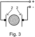
- the normal directions of the coupling surfaces are oriented perpendicular to one another, in particular wherein the normal directions are also perpendicular to the direction of the primary conductor.
- the normal directions of the coupling surfaces are oriented parallel or at an angle of up to 40 ° to each other, in particular wherein the normal directions are also perpendicular to the direction of the primary conductor.
- a stationarily arranged means for data transmission also comprises a corresponding coupling element, in particular wherein data transmission between one or more cars and the stationarily arranged means is provided.
- an alternating current is impressed into the primary conductor, in particular with a frequency between 10 and 500 kHz, in particular with more than 1 or even 10 amperes.
- the advantage here is that high power in the range of kilowatts are transferable, with only small losses occur.
- the secondary coil has a capacitance connected in series or in parallel such that the associated resonant frequency essentially corresponds to the frequency of the alternating current impressed into the primary conductor.
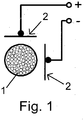
- the primary conductor 1 is shown, which is designed elongated and in which an alternating current is impressed, preferably with a frequency between 10 and 500 kHz.
- a carriage is movably arranged, which comprises a secondary conductor inductively coupled to the primary coil 1, which is a capacitor connected in parallel or in series such that the associated resonant frequency substantially the frequency of the impressed in the primary conductor alternating current equivalent.
- the strength of the alternating current can exceed 1 or even 10 amperes permanently.
- means for data transmission are provided on this carriage which can be moved along the primary conductor 1.
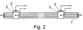
- These include at least those in the FIGS. 1 and 2 These are designed as rectangular metal plates whose normal direction are oriented perpendicular to each other and perpendicular to the primary conductor direction.
- the primary conductor consists of a number of stranded wires, which are each made electrically insulated from each other.
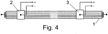
- FIG. 2 Further analogously executed coupling surfaces 3 are shown, which are connected to a voltage detecting means, whereby thus the applied voltage between the metal plates is detected.
- the coupling surfaces 3 are arranged either on a further movable carriage or stationary.
- a voltage detection means and the coupling surfaces 3 a high-frequency AC voltage source connected to then allow in this way a bidirectional data transmission.
- Different frequency bands can be used for the data transmission, preferably above 10 MHz up to 10 GHz.
- an AC power source 50 has a first electrical terminal a1 for a forward conductor, which is designed as a primary conductor 1, and a further electrical terminal a2 for a return conductor, which is designed as a primary conductor 1.
- the entire primary conductor is laid as a closed loop, in particular as an elongated conductor loop.
- Forward conductor and return conductor are electrically connected at their end facing away from the AC power source 50.
- the respective strand ends are preferably tinned together.
- the word perpendicular used in this document is not to be understood as an exact angle of 90 ° but also angles between 50 ° and 130 ° to understand, so minor deviations from the mathematically exact vertical direction.
- the coupling surfaces (2,3) are seen from the primary conductor, although designed substantially flat, but the planar design also allows small undulating deviations from the ideal plane, the associated amplitude amount to 20% of the distance of the coupling surface to the surface of the primary conductor may.
Landscapes
- Engineering & Computer Science (AREA)
- Computer Networks & Wireless Communication (AREA)
- Signal Processing (AREA)
- Power Engineering (AREA)
- Near-Field Transmission Systems (AREA)
Claims (10)
- Dispositif de transmission d'énergie sans contact,
dans lequel un conducteur primaire peut être alimenté électriquement à partir d'une source de courant alternatif,
dans lequel le conducteur primaire comprend un conducteur aller et un conducteur retour, qui sont connectés chacun par l'une de leurs extrémités à un potentiel respectif de la source de courant alternatif et connectés entre eux par leur autre extrémité respective,
dans lequel au moins un chariot mobile le long du conducteur primaire est prévu,
dans lequel un moyen de transmission de données est prévu sur le chariot,
dans lequel le conducteur aller et le conducteur retour sont composés chacun de fils torsadés individuels isolés électriquement les uns des autres,
dans lequel le moyen de transmission de données comprend un premier élément de couplage qui est couplé capacitivement aux fils torsadés du conducteur aller de telle sorte que des tensions de signal peuvent être couplées dans les fils torsadés du conducteur aller et/ou découplées de ceux-ci,
dans lequel le moyen de transmission de données comprend un second élément de couplage qui est couplé capacitivement aux fils torsadés du conducteur retour de telle sorte que des tensions de signal peuvent être couplées dans les fils torsadés du conducteur retour et/ou découplées de ceux-ci,
caractérisé en ce que
chaque élément de couplage comprend deux surfaces de couplage et que les directions normales des surfaces de couplage sont orientées perpendiculairement l'une à l'autre. - Dispositif selon au moins l'une des revendications précédentes,
dans lequel le chariot échange des données via le conducteur aller de sorte qu'un premier canal de données est formé,
dans lequel le chariot échange des données via le conducteur retour de sorte qu'un second canal de données est formé,
les premier et second canaux de données étant indépendants l'un de l'autre. - Dispositif selon au moins l'une des revendications précédentes,
dans lequel les fils torsadés sont munis chacun d'une couche d'isolation électrique sur leur circonférence extérieure. - Dispositif selon au moins l'une des revendications précédentes,
dans lequel chaque élément de couplage comprend au moins deux surfaces de couplage auxquelles une tension peut être appliquée, en particulier pour la transmission de données. - Dispositif selon au moins l'une des revendications précédentes,
dans lequel chaque élément de couplage comprend au moins deux surfaces de couplage, la tension appliquée entre les surfaces de couplage étant détectable, en particulier pour la réception de données. - Dispositif selon au moins l'une des revendications précédentes,
dans lequel les surfaces de couplage sont métalliques et/ou sensiblement planes. - Dispositif selon au moins l'une des revendications précédentes,
dans lequel les directions normales sont également perpendiculaires à la direction du conducteur primaire. - Dispositif selon au moins l'une des revendications précédentes,
dans lequel un moyen fixe pour la transmission de données comprend également un élément de couplage correspondant, en particulier dans lequel une transmission de données entre un ou plusieurs chariots et le moyen fixe est prévue. - Dispositif selon au moins l'une des revendications précédentes,
dans lequel un courant alternatif est appliqué dans le conducteur primaire par la source de tension alternative, en particulier à une fréquence comprise entre 10 et 500 kHz, en particulier de plus de 1 ou même 10 ampères. - Dispositif selon au moins l'une des revendications précédentes,
dans lequel un condensateur est connecté en série ou en parallèle à une bobine secondaire couplée par induction au conducteur primaire de telle sorte que la fréquence de résonance associée correspond sensiblement à la fréquence du courant alternatif appliqué dans le conducteur primaire.
Applications Claiming Priority (2)
| Application Number | Priority Date | Filing Date | Title |
|---|---|---|---|
| DE102010009073A DE102010009073B4 (de) | 2010-02-23 | 2010-02-23 | Anordnung zur berührungslosen Energieübertragung |
| PCT/EP2011/000381 WO2011103954A1 (fr) | 2010-02-23 | 2011-01-28 | Dispositif de transfert d'énergie sans contact |
Publications (2)
| Publication Number | Publication Date |
|---|---|
| EP2540004A1 EP2540004A1 (fr) | 2013-01-02 |
| EP2540004B1 true EP2540004B1 (fr) | 2018-07-25 |
Family
ID=43828127
Family Applications (1)
| Application Number | Title | Priority Date | Filing Date |
|---|---|---|---|
| EP11704922.1A Active EP2540004B1 (fr) | 2010-02-23 | 2011-01-28 | Dispositif de transfert d'énergie sans contact |
Country Status (4)
| Country | Link |
|---|---|
| EP (1) | EP2540004B1 (fr) |
| CN (1) | CN102771056B (fr) |
| DE (1) | DE102010009073B4 (fr) |
| WO (1) | WO2011103954A1 (fr) |
Family Cites Families (8)
| Publication number | Priority date | Publication date | Assignee | Title |
|---|---|---|---|---|
| DE4446779C2 (de) | 1994-12-24 | 1996-12-19 | Daimler Benz Ag | Anordnung zur berührungslosen induktiven Übertragung elektrischer Leistung |
| WO1999050806A1 (fr) * | 1998-04-01 | 1999-10-07 | Barret Massey Cunningham | Systeme de signalisation base sur un courant d'induction et le transfert de signaux |
| DE10021670A1 (de) * | 2000-05-05 | 2001-11-15 | Schleifring Und Appbau Gmbh | Vorrichtung zur breitbandigen elektrischen Signal- bzw. Energieübertragung mit Übertragungsstrecke mit Richtkopplern |
| DE10131905B4 (de) * | 2001-07-04 | 2005-05-19 | Wampfler Aktiengesellschaft | Vorrichtung zur induktiven Übertragung elektrischer Energie |
| DE102004031580B4 (de) * | 2004-06-29 | 2007-02-01 | Sew-Eurodrive Gmbh & Co. Kg | Anordnung zur berührungslosen induktiven Energieübertragung an bewegbare Vorrichtungen |
| DE102007051917B4 (de) * | 2006-11-27 | 2017-03-30 | Sew-Eurodrive Gmbh & Co Kg | Aktor, insbesondere Linearantrieb, und Anlage oder Maschine |
| DE102007059046B3 (de) * | 2007-12-06 | 2009-04-30 | Sew-Eurodrive Gmbh & Co. Kg | Vorrichtung zur berührungslosen Energieübertragung und Anlage mit elektrischen Verbrauchern |
| DE102008064673B4 (de) | 2008-11-26 | 2013-05-29 | Sew-Eurodrive Gmbh & Co. Kg | Anordnung zur berührungslosen Energieübertragung |
-
2010
- 2010-02-23 DE DE102010009073A patent/DE102010009073B4/de active Active
-
2011
- 2011-01-28 WO PCT/EP2011/000381 patent/WO2011103954A1/fr active Application Filing
- 2011-01-28 CN CN201180010762.4A patent/CN102771056B/zh active Active
- 2011-01-28 EP EP11704922.1A patent/EP2540004B1/fr active Active
Non-Patent Citations (1)
| Title |
|---|
| None * |
Also Published As
| Publication number | Publication date |
|---|---|
| CN102771056A (zh) | 2012-11-07 |
| DE102010009073A1 (de) | 2011-08-25 |
| WO2011103954A1 (fr) | 2011-09-01 |
| EP2540004A1 (fr) | 2013-01-02 |
| CN102771056B (zh) | 2015-05-06 |
| DE102010009073B4 (de) | 2013-01-17 |
Similar Documents
| Publication | Publication Date | Title |
|---|---|---|
| EP2225814B1 (fr) | Dispositif de transmission d'énergie sans contact et installation dotée de consommateurs électriques | |
| DE10326614A1 (de) | Transportsystem | |
| EP2673157B1 (fr) | Dispositif de transmission d'énergie et de communication par induction | |
| EP1855909B1 (fr) | Installation et procédé pour déterminer une position | |
| EP2371069B1 (fr) | Agencement pour le transfert d'énergie sans contact | |
| DE102007023343A1 (de) | Übertragerkopf und Anlage | |
| DE102007024293B4 (de) | Anlage mit Primärleitersystem und bewegbar angeordneter Vorrichtung | |
| EP2700140B1 (fr) | Système de transmission inductive d'énergie à un récepteur électrique | |
| EP2540004B1 (fr) | Dispositif de transfert d'énergie sans contact | |
| DE102006025461B4 (de) | Übertragerkopf für eine Anlage zur berührungslosen Energieübertragung und Anlage mit einem Übertragerkopf | |
| EP2540003B1 (fr) | Système de transmission d'énergie sans contact | |
| EP2029386B1 (fr) | Procédé et dispositif pour fabriquer un module électronique et module électronique | |
| EP4018464B1 (fr) | Système de transfert de puissance sans contact d'une ligne primaire à un enroulement | |
| EP2168220B1 (fr) | Élément de terminaison de ligne et dispositif de transmission sans contact de puissance et de données | |
| DE102009024694B4 (de) | Anlage und Verfahren zum Betreiben einer Anlage | |
| DE102015011950A1 (de) | Ladesystem, umfassend ein auf einem Boden verfahrbares Fahrzeug und ein auf dem Boden angeordnetes Aufnahmeteil, und Verfahren zum Betreiben eines Systems zur induktiven Übertragung elektrischer Energie von einer Primärspule an eine Sekundärspule | |
| DE102010049144A1 (de) | Anordnung zum Austausch oder zumindest Empfang von elektromagnetischen Wellen |
Legal Events
| Date | Code | Title | Description |
|---|---|---|---|
| PUAI | Public reference made under article 153(3) epc to a published international application that has entered the european phase |
Free format text: ORIGINAL CODE: 0009012 |
|
| 17P | Request for examination filed |
Effective date: 20120924 |
|
| AK | Designated contracting states |
Kind code of ref document: A1 Designated state(s): AL AT BE BG CH CY CZ DE DK EE ES FI FR GB GR HR HU IE IS IT LI LT LU LV MC MK MT NL NO PL PT RO RS SE SI SK SM TR |
|
| DAX | Request for extension of the european patent (deleted) | ||
| GRAP | Despatch of communication of intention to grant a patent |
Free format text: ORIGINAL CODE: EPIDOSNIGR1 |
|
| RIC1 | Information provided on ipc code assigned before grant |
Ipc: H04B 5/02 20060101ALI20180122BHEP Ipc: H04B 5/00 20060101AFI20180122BHEP Ipc: H02J 50/12 20160101ALI20180122BHEP |
|
| STAA | Information on the status of an ep patent application or granted ep patent |
Free format text: STATUS: GRANT OF PATENT IS INTENDED |
|
| INTG | Intention to grant announced |
Effective date: 20180301 |
|
| GRAS | Grant fee paid |
Free format text: ORIGINAL CODE: EPIDOSNIGR3 |
|
| GRAA | (expected) grant |
Free format text: ORIGINAL CODE: 0009210 |
|
| STAA | Information on the status of an ep patent application or granted ep patent |
Free format text: STATUS: THE PATENT HAS BEEN GRANTED |
|
| AK | Designated contracting states |
Kind code of ref document: B1 Designated state(s): AL AT BE BG CH CY CZ DE DK EE ES FI FR GB GR HR HU IE IS IT LI LT LU LV MC MK MT NL NO PL PT RO RS SE SI SK SM TR |
|
| REG | Reference to a national code |
Ref country code: GB Ref legal event code: FG4D Free format text: NOT ENGLISH |
|
| REG | Reference to a national code |
Ref country code: CH Ref legal event code: EP |
|
| REG | Reference to a national code |
Ref country code: AT Ref legal event code: REF Ref document number: 1022875 Country of ref document: AT Kind code of ref document: T Effective date: 20180815 |
|
| REG | Reference to a national code |
Ref country code: IE Ref legal event code: FG4D Free format text: LANGUAGE OF EP DOCUMENT: GERMAN |
|
| REG | Reference to a national code |
Ref country code: DE Ref legal event code: R096 Ref document number: 502011014503 Country of ref document: DE |
|
| REG | Reference to a national code |
Ref country code: NL Ref legal event code: MP Effective date: 20180725 |
|
| REG | Reference to a national code |
Ref country code: LT Ref legal event code: MG4D |
|
| PG25 | Lapsed in a contracting state [announced via postgrant information from national office to epo] |
Ref country code: NL Free format text: LAPSE BECAUSE OF FAILURE TO SUBMIT A TRANSLATION OF THE DESCRIPTION OR TO PAY THE FEE WITHIN THE PRESCRIBED TIME-LIMIT Effective date: 20180725 |
|
| PG25 | Lapsed in a contracting state [announced via postgrant information from national office to epo] |
Ref country code: LT Free format text: LAPSE BECAUSE OF FAILURE TO SUBMIT A TRANSLATION OF THE DESCRIPTION OR TO PAY THE FEE WITHIN THE PRESCRIBED TIME-LIMIT Effective date: 20180725 Ref country code: RS Free format text: LAPSE BECAUSE OF FAILURE TO SUBMIT A TRANSLATION OF THE DESCRIPTION OR TO PAY THE FEE WITHIN THE PRESCRIBED TIME-LIMIT Effective date: 20180725 Ref country code: IS Free format text: LAPSE BECAUSE OF FAILURE TO SUBMIT A TRANSLATION OF THE DESCRIPTION OR TO PAY THE FEE WITHIN THE PRESCRIBED TIME-LIMIT Effective date: 20181125 Ref country code: PL Free format text: LAPSE BECAUSE OF FAILURE TO SUBMIT A TRANSLATION OF THE DESCRIPTION OR TO PAY THE FEE WITHIN THE PRESCRIBED TIME-LIMIT Effective date: 20180725 Ref country code: NO Free format text: LAPSE BECAUSE OF FAILURE TO SUBMIT A TRANSLATION OF THE DESCRIPTION OR TO PAY THE FEE WITHIN THE PRESCRIBED TIME-LIMIT Effective date: 20181025 Ref country code: GR Free format text: LAPSE BECAUSE OF FAILURE TO SUBMIT A TRANSLATION OF THE DESCRIPTION OR TO PAY THE FEE WITHIN THE PRESCRIBED TIME-LIMIT Effective date: 20181026 Ref country code: FI Free format text: LAPSE BECAUSE OF FAILURE TO SUBMIT A TRANSLATION OF THE DESCRIPTION OR TO PAY THE FEE WITHIN THE PRESCRIBED TIME-LIMIT Effective date: 20180725 Ref country code: SE Free format text: LAPSE BECAUSE OF FAILURE TO SUBMIT A TRANSLATION OF THE DESCRIPTION OR TO PAY THE FEE WITHIN THE PRESCRIBED TIME-LIMIT Effective date: 20180725 Ref country code: BG Free format text: LAPSE BECAUSE OF FAILURE TO SUBMIT A TRANSLATION OF THE DESCRIPTION OR TO PAY THE FEE WITHIN THE PRESCRIBED TIME-LIMIT Effective date: 20181025 |
|
| REG | Reference to a national code |
Ref country code: CH Ref legal event code: PK Free format text: BERICHTIGUNGEN |
|
| RIC2 | Information provided on ipc code assigned after grant |
Ipc: H04B 5/00 20060101AFI20180122BHEP Ipc: H04B 5/02 20060101ALI20180122BHEP Ipc: H02J 50/12 20160101ALI20180122BHEP |
|
| PG25 | Lapsed in a contracting state [announced via postgrant information from national office to epo] |
Ref country code: HR Free format text: LAPSE BECAUSE OF FAILURE TO SUBMIT A TRANSLATION OF THE DESCRIPTION OR TO PAY THE FEE WITHIN THE PRESCRIBED TIME-LIMIT Effective date: 20180725 Ref country code: LV Free format text: LAPSE BECAUSE OF FAILURE TO SUBMIT A TRANSLATION OF THE DESCRIPTION OR TO PAY THE FEE WITHIN THE PRESCRIBED TIME-LIMIT Effective date: 20180725 Ref country code: AL Free format text: LAPSE BECAUSE OF FAILURE TO SUBMIT A TRANSLATION OF THE DESCRIPTION OR TO PAY THE FEE WITHIN THE PRESCRIBED TIME-LIMIT Effective date: 20180725 |
|
| REG | Reference to a national code |
Ref country code: DE Ref legal event code: R097 Ref document number: 502011014503 Country of ref document: DE |
|
| PG25 | Lapsed in a contracting state [announced via postgrant information from national office to epo] |
Ref country code: CZ Free format text: LAPSE BECAUSE OF FAILURE TO SUBMIT A TRANSLATION OF THE DESCRIPTION OR TO PAY THE FEE WITHIN THE PRESCRIBED TIME-LIMIT Effective date: 20180725 Ref country code: IT Free format text: LAPSE BECAUSE OF FAILURE TO SUBMIT A TRANSLATION OF THE DESCRIPTION OR TO PAY THE FEE WITHIN THE PRESCRIBED TIME-LIMIT Effective date: 20180725 Ref country code: RO Free format text: LAPSE BECAUSE OF FAILURE TO SUBMIT A TRANSLATION OF THE DESCRIPTION OR TO PAY THE FEE WITHIN THE PRESCRIBED TIME-LIMIT Effective date: 20180725 Ref country code: ES Free format text: LAPSE BECAUSE OF FAILURE TO SUBMIT A TRANSLATION OF THE DESCRIPTION OR TO PAY THE FEE WITHIN THE PRESCRIBED TIME-LIMIT Effective date: 20180725 Ref country code: EE Free format text: LAPSE BECAUSE OF FAILURE TO SUBMIT A TRANSLATION OF THE DESCRIPTION OR TO PAY THE FEE WITHIN THE PRESCRIBED TIME-LIMIT Effective date: 20180725 |
|
| PG25 | Lapsed in a contracting state [announced via postgrant information from national office to epo] |
Ref country code: DK Free format text: LAPSE BECAUSE OF FAILURE TO SUBMIT A TRANSLATION OF THE DESCRIPTION OR TO PAY THE FEE WITHIN THE PRESCRIBED TIME-LIMIT Effective date: 20180725 Ref country code: SK Free format text: LAPSE BECAUSE OF FAILURE TO SUBMIT A TRANSLATION OF THE DESCRIPTION OR TO PAY THE FEE WITHIN THE PRESCRIBED TIME-LIMIT Effective date: 20180725 Ref country code: SM Free format text: LAPSE BECAUSE OF FAILURE TO SUBMIT A TRANSLATION OF THE DESCRIPTION OR TO PAY THE FEE WITHIN THE PRESCRIBED TIME-LIMIT Effective date: 20180725 |
|
| PLBE | No opposition filed within time limit |
Free format text: ORIGINAL CODE: 0009261 |
|
| STAA | Information on the status of an ep patent application or granted ep patent |
Free format text: STATUS: NO OPPOSITION FILED WITHIN TIME LIMIT |
|
| 26N | No opposition filed |
Effective date: 20190426 |
|
| PG25 | Lapsed in a contracting state [announced via postgrant information from national office to epo] |
Ref country code: SI Free format text: LAPSE BECAUSE OF FAILURE TO SUBMIT A TRANSLATION OF THE DESCRIPTION OR TO PAY THE FEE WITHIN THE PRESCRIBED TIME-LIMIT Effective date: 20180725 Ref country code: MC Free format text: LAPSE BECAUSE OF FAILURE TO SUBMIT A TRANSLATION OF THE DESCRIPTION OR TO PAY THE FEE WITHIN THE PRESCRIBED TIME-LIMIT Effective date: 20180725 |
|
| REG | Reference to a national code |
Ref country code: CH Ref legal event code: PL |
|
| PG25 | Lapsed in a contracting state [announced via postgrant information from national office to epo] |
Ref country code: LU Free format text: LAPSE BECAUSE OF NON-PAYMENT OF DUE FEES Effective date: 20190128 |
|
| REG | Reference to a national code |
Ref country code: BE Ref legal event code: MM Effective date: 20190131 |
|
| REG | Reference to a national code |
Ref country code: IE Ref legal event code: MM4A |
|
| PG25 | Lapsed in a contracting state [announced via postgrant information from national office to epo] |
Ref country code: BE Free format text: LAPSE BECAUSE OF NON-PAYMENT OF DUE FEES Effective date: 20190131 |
|
| PG25 | Lapsed in a contracting state [announced via postgrant information from national office to epo] |
Ref country code: CH Free format text: LAPSE BECAUSE OF NON-PAYMENT OF DUE FEES Effective date: 20190131 Ref country code: LI Free format text: LAPSE BECAUSE OF NON-PAYMENT OF DUE FEES Effective date: 20190131 |
|
| PG25 | Lapsed in a contracting state [announced via postgrant information from national office to epo] |
Ref country code: IE Free format text: LAPSE BECAUSE OF NON-PAYMENT OF DUE FEES Effective date: 20190128 |
|
| REG | Reference to a national code |
Ref country code: AT Ref legal event code: MM01 Ref document number: 1022875 Country of ref document: AT Kind code of ref document: T Effective date: 20190128 |
|
| PG25 | Lapsed in a contracting state [announced via postgrant information from national office to epo] |
Ref country code: TR Free format text: LAPSE BECAUSE OF FAILURE TO SUBMIT A TRANSLATION OF THE DESCRIPTION OR TO PAY THE FEE WITHIN THE PRESCRIBED TIME-LIMIT Effective date: 20180725 |
|
| PG25 | Lapsed in a contracting state [announced via postgrant information from national office to epo] |
Ref country code: AT Free format text: LAPSE BECAUSE OF NON-PAYMENT OF DUE FEES Effective date: 20190128 |
|
| PG25 | Lapsed in a contracting state [announced via postgrant information from national office to epo] |
Ref country code: PT Free format text: LAPSE BECAUSE OF FAILURE TO SUBMIT A TRANSLATION OF THE DESCRIPTION OR TO PAY THE FEE WITHIN THE PRESCRIBED TIME-LIMIT Effective date: 20181125 Ref country code: MT Free format text: LAPSE BECAUSE OF FAILURE TO SUBMIT A TRANSLATION OF THE DESCRIPTION OR TO PAY THE FEE WITHIN THE PRESCRIBED TIME-LIMIT Effective date: 20180725 |
|
| PG25 | Lapsed in a contracting state [announced via postgrant information from national office to epo] |
Ref country code: CY Free format text: LAPSE BECAUSE OF FAILURE TO SUBMIT A TRANSLATION OF THE DESCRIPTION OR TO PAY THE FEE WITHIN THE PRESCRIBED TIME-LIMIT Effective date: 20180725 |
|
| PG25 | Lapsed in a contracting state [announced via postgrant information from national office to epo] |
Ref country code: HU Free format text: LAPSE BECAUSE OF FAILURE TO SUBMIT A TRANSLATION OF THE DESCRIPTION OR TO PAY THE FEE WITHIN THE PRESCRIBED TIME-LIMIT; INVALID AB INITIO Effective date: 20110128 |
|
| PG25 | Lapsed in a contracting state [announced via postgrant information from national office to epo] |
Ref country code: MK Free format text: LAPSE BECAUSE OF FAILURE TO SUBMIT A TRANSLATION OF THE DESCRIPTION OR TO PAY THE FEE WITHIN THE PRESCRIBED TIME-LIMIT Effective date: 20180725 |
|
| PGFP | Annual fee paid to national office [announced via postgrant information from national office to epo] |
Ref country code: GB Payment date: 20231207 Year of fee payment: 14 |
|
| PGFP | Annual fee paid to national office [announced via postgrant information from national office to epo] |
Ref country code: FR Payment date: 20231212 Year of fee payment: 14 |
|
| PGFP | Annual fee paid to national office [announced via postgrant information from national office to epo] |
Ref country code: DE Payment date: 20240131 Year of fee payment: 14 |