EP2369958B1 - Doppelantrieb für möbel - Google Patents
Doppelantrieb für möbel Download PDFInfo
- Publication number
- EP2369958B1 EP2369958B1 EP09756485A EP09756485A EP2369958B1 EP 2369958 B1 EP2369958 B1 EP 2369958B1 EP 09756485 A EP09756485 A EP 09756485A EP 09756485 A EP09756485 A EP 09756485A EP 2369958 B1 EP2369958 B1 EP 2369958B1
- Authority
- EP
- European Patent Office
- Prior art keywords
- spindle
- functional unit
- lever
- double drive
- drive according
- Prior art date
- Legal status (The legal status is an assumption and is not a legal conclusion. Google has not performed a legal analysis and makes no representation as to the accuracy of the status listed.)
- Not-in-force
Links
- 230000033001 locomotion Effects 0.000 claims description 21
- 238000006073 displacement reaction Methods 0.000 claims 1
- 230000005540 biological transmission Effects 0.000 description 5
- 239000003638 chemical reducing agent Substances 0.000 description 3
- 230000005484 gravity Effects 0.000 description 3
- 239000011295 pitch Substances 0.000 description 3
- 238000005096 rolling process Methods 0.000 description 3
- 230000007423 decrease Effects 0.000 description 2
- 238000000034 method Methods 0.000 description 2
- 230000002441 reversible effect Effects 0.000 description 2
- 230000015572 biosynthetic process Effects 0.000 description 1
- 238000013016 damping Methods 0.000 description 1
- 230000009977 dual effect Effects 0.000 description 1
- 238000005755 formation reaction Methods 0.000 description 1
- 238000004519 manufacturing process Methods 0.000 description 1
- 239000000463 material Substances 0.000 description 1
- 230000003014 reinforcing effect Effects 0.000 description 1
Images




Classifications
-
- A—HUMAN NECESSITIES
- A47—FURNITURE; DOMESTIC ARTICLES OR APPLIANCES; COFFEE MILLS; SPICE MILLS; SUCTION CLEANERS IN GENERAL
- A47C—CHAIRS; SOFAS; BEDS
- A47C20/00—Head-, foot- or like rests for beds, sofas or the like
- A47C20/04—Head-, foot- or like rests for beds, sofas or the like with adjustable inclination
- A47C20/041—Head-, foot- or like rests for beds, sofas or the like with adjustable inclination by electric motors
Definitions
- the invention relates to a double drive for furniture for adjusting two spatially separate functional units of a piece of furniture, with a housing, with a drive motor which is coupled to a Drehbaumreduziergetriebe whose rotating driven output member is in operative connection with an actuating element, and that in traversability of the control element in the direction of the first functional unit of the furniture after reaching a certain travel, the second functional unit of the furniture is adjustable.
- a double drive of the type in question is used in a preferred embodiment for adjusting the backrest and the foot part of a slatted frame.
- the previously used double drives are equipped with two drive motors, which can be actuated independently of each other via a corresponding control unit.
- Each drive acts on the Drehierereduziergetriebe on a spindle drive, which cooperates with the adjusting lever of the respective functional unit.
- the invention has for its object to design a double drive of the type described in more detail so that not only the second functional unit is adjusted by moving the actuator in the direction of the first functional unit, but that both functional units, in a slatted frame, the backrest and the footboard at least partially individually adjustable.
- the object is achieved by the coupled with the output member of the Drehierereduziergetriebes actuator is movable in its longitudinal direction, secured against rotation spindle with an external thread that the spindle is movable in either direction to the first functional unit or towards the second functional unit that the End face of the spindle when moving in the direction of the first functional unit acts directly or indirectly on an adjusting lever of the first functional unit, and that between the second functional unit facing front end region of the thrust spindle and the adjusting lever of the second functional unit, a pushing device is arranged.
- the pushing device When moving the spindle acting as a thrust spindle in the direction of the first functional unit, the pushing device acts in such a way that either the adjusting lever of the second functional unit is pivoted immediately or else with a time delay.
- the spindle which can be moved in this direction acts on the pushing device, so that the pressure forces are transmitted to the adjusting lever of the second functional unit.
- the spindle moves in the direction of the adjusting lever of the second functional unit.
- a reversible DC motor operates the input member of a speed reducer, which is formed, for example, as a worm or a gear, wherein a portion of the motor shaft itself may also be formed as a worm or as a gear.
- the output member of the Drehierereduziergetriebe is designed as a gear, but preferably as a worm and is in operative connection with a nut thread, wherein the threads of the nut thread with the threads of the external thread of the spindle are engaged.
- the threads of the nut thread are preferably formed on or in the output member of the Drehierereduziergetriebes or formed therein.
- the bearing itself can form a one-piece molded part with the housing parts of the double drive.
- a transmission housing is provided which receives the gears.
- the transmission housing may be designed in several parts and is inserted positively in the housing of the double drive.
- sound and vibration damping means are provided, which are at least partially or selectively applied or formed, for example, on or around the engine and / or the transmission.
- the thrust device is designed in the manner of a slotted guide.
- This slide guide is designed to that the linear movement of the spindle causes a rotational movement of the adjusting lever of the second functional unit.
- This thrust device or the slotted guide has two sliding blocks, which are positively coupled together via at least one pivotally mounted control lever. If the spindle is moved in the direction of the first functional unit, the two sliding blocks are moved in opposite directions, so that the sliding block facing away from the spindle presses on the adjusting lever. In the basic position of the spindle, ie when the two functional units are lowered, the two sliding blocks can be in contact with each other.
- the guides in the sliding blocks can then be designed so that only after a certain travel of the spindle in the direction of the first functional unit of the adjusting lever of the second functional unit is pivoted.
- the sliding blocks can also be in the normal position at a certain distance from each other. When moving the spindle in the direction of the first functional unit, the distance of the mutually facing surfaces of the sliding blocks increases by a pivoting movement of the control lever and at a certain distance of the facing surfaces of the sliding blocks of the control lever of the second functional unit is pivoted.
- the sliding block facing the drive motor and the Drehierereduziergetriebe is fixedly connected to the spindle, and that the control lever is pivotable about an axis transverse to the spindle axis.
- this axis is considered to be stationary.
- the control lever or the control lever are arranged in the sliding blocks or laterally next to the sliding blocks, and that each control lever is provided in the pivot axis remote from the areas lying with a guide pin, and that each guide pin in the control grooves of Sliding stones intervenes.
- the guide pins may also be formed as a kind of continuous guide axis.
- the distances of the guide pin to the pivot axis of the control lever or the control lever are equal or approximately equal.
- the heights of the control grooves in the sliding blocks are the same or approximately the same, being understood by the heights transverse to the spindle resulting distances.
- each control groove at least one sliding block has an inclined or curved portion to the spindle, the included between these sections and the central longitudinal axis of the spindle dull Angles are.
- cam groove of the coupled with the spindle sliding block S-shaped is designed such that the adjoining the inclined portion sections are parallel and spaced from each other and parallel to the central longitudinal axis of the spindle.
- the thrust device or the sliding guide is designed so that in the basic position of the spindle, i. with lowered functional units, the guide pins of each control lever are located at the mutually remote areas of the guide grooves of the sliding blocks, and that in the end position of the movable spindle in the direction of the first functional unit, the positions of the guide pins are reversed. Furthermore, the arrangement is advantageously made such that the control pin engaging in the control groove of the sliding block coupled to the spindle forms the drive member of the control lever.
- the transverse to the spindle pivot axis of the control lever is formed by a journal. It may also be advantageous if the journal of the control lever or the control lever is slidably disposed in a guide of the housing in the direction of movement of the spindle. This guide of the housing is designed in the manner of a long hole. The time delay of the adjustment of the adjusting lever of the second functional unit could also be achieved by abutting the axle journal in an end region of the guide during a predetermined adjustment of the first functional unit. Previously, he was moved to this position.
- the guide blocks described in more detail have control grooves, which are in operative connection with guide pins or which are formed with a guide pin formed as a guide axis.
- the sliding blocks are designed as a kind of open sliding blocks, wherein the guide pins or the guide axes are at least partially in operative connection with inclined planes and / or curved, inclined or curved guideways.
- the inclined planes or the curved guideways are at least partially attached or formed on a front end region of the respective sliding block.
- these are preferably formed as sliding surfaces, but according to another embodiment may also be formed at least in sections as a rolling guide.
- the course and the contour of the guideways are designed differently.
- both uniform movements and according to other further embodiments non-uniform movements of the sliding block can be generated, which is in operative connection with the adjusting lever of the second functional unit.
- the respective front end region of the spindle is directly or indirectly in operative connection with the adjusting lever of the respective functional unit. Furthermore, the said operative connection takes place in the manner of a loose application that the furniture components, which are connected to the respective adjusting lever, are adjusted by the operation of the electric motor against gravity, with a provision of the furniture components by gravity itself.
- a mechanical decoupling device which, for example, in shape a clutch or a disengageable pawl with a component of the drive train, for example with a gear of Drehierereduziergetriebes, with the spindle, with the control lever, with an adjusting lever or with a furniture component in such a connection, so that at least in power failure, the adjustable furniture component manually, for example in the direction of gravity, can be adjusted.
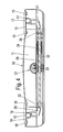
- the in the FIGS. 4 to 15 shown embodiments of double drives 10 each have a housing 11, which are designed according to the different drive elements.
- the housings 11 are provided with reinforcing ribs and the like according to the loads.
- the double drives 10 are on two parallel and spaced apart shafts 12, 13 suspended.
- the shafts 12, 13 are parts of not shown functional units of a piece of furniture.
- the double drives 10 for adjusting the backrest of a slatted base, which preferably forms the first functional unit and used for adjusting a foot part, which preferably forms the second functional unit.
- the shaft 12 of the first functional unit and the shaft 13 of the second functional unit is assigned. They consist of tubes that are rotatable, displaceable or pivotally mounted in the furniture.
- each closer 14, 15 is provided with two webs 18, 19 lying on both sides of the shafts 12, 13. To lock the double drive 10, the closer 14, 15 are pushed in the direction of the central longitudinal axes on the recesses.
- the walls of the housing 11 may also be designed so that the closer 14, 15 transverse to the central longitudinal axes of the shafts 12, 13 are attached to the housing 11.
- each an adjusting lever 20, 21 rotatably mounted on the shafts 12, 13 .
- the mutually facing surfaces of the two adjusting levers 20, 21 contact adjusting elements explained in greater detail.
- each double drive 10 is equipped with a well-known drive motor 22, which is a reversible DC motor and is operated with a DC safety voltage.
- both adjusting levers 20, 21 are adjusted by a single drive motor 22 via a Drehierereduziergetriebe 23 and explained in more detail drive units.
- the drive motor 22 is in the standard versions flanged to an outer wall of the housing 11, but may also be mounted within the housing 11.
- the Drehierereduziergetriebe 23 is preferably a worm drive, wherein the worm wheel forms the output member of the Drehierereduziergetriebes 23.
- the DC motor formed drive motor 22 forms with the housing of the Drehierereduziergetriebes 23 a compact unit, bearings in the form of rolling and / or plain bearings support the output member of the Drehierereduziergetriebes 23.
- the housing of the drive motor 22 and transmission can form a compact unit, so that a compact drive gear motor is formed, but it can also be a drive motor 22 attached to a transmission housing.
- the spindle 24 is secured against rotation.
- the output member of the Drehierereduziergetriebes 23 it is moved depending on the direction of rotation of this output member either in the direction of the adjusting lever 20 of the first functional unit or in the direction of the adjusting lever 21 of the second functional unit.
- the driven member of the Drehierereduziergetriebes 23 has a centrally disposed internally threaded bore, wherein the threads of the internally threaded bore with the external threads of the spindle 24 are engaged.
- the threads of the two sides of the Drehierereduziergetriebes 23 sections may be opposite directions, but they may also be the same according to the illustrated embodiment.
- a pressure piece 32 is placed on the end region of the spindle 24 for adjusting the lever 20 of the first functional unit.
- a hollow spindle 33 is placed, which may have the corresponding threads of the spindle 24 extending inner threads.
- the hollow spindle 33 is also provided with an external thread whose threads are opposite to those of the spindle 24.
- the hollow spindle 33 is rotatable, but not displaceable in the longitudinal direction of the spindle 24. In the illustrated embodiment, it is rotationally fixed with one end coupled to the output member of the Drehierereduziergetriebes 23.
- a spindle nut 34 is placed, which is secured against rotation and whose threads correspond to the external threads of the hollow spindle 33.
- a sliding piece 35 is still used, which contacts the adjusting lever 21.
- FIG. 5 shows the two end positions of the adjusting lever 20, 21, wherein the adjustment of the adjusting lever 21 in about a quarter to half of the total adjustability of the second functional unit occupies.
- the direction of rotation of the drive motor 23 is reversed, so that the spindle 24 moves in the direction of the adjusting lever 21.
- the spindle nut 34 moves in the direction of the Drehierereduziergetriebe 23 and the spindle 24 takes the sliding piece 35 and moves according to the FIG. 6 the adjusting lever 21 in the end position of the second functional unit.
- the directions of rotation are reversed, so that the adjustment is made by the weight of the functional units. In the basic position of the drive units, the functional units are lowered.
- the double drive is in turn equipped with a drive motor 22 and a Drehierereduziergetriebe 23.
- the output member of the Drehierereduziergetriebes is operatively connected to a spindle 24 which is secured against rotation and is movable in opposite directions.
- the output member of the Drehierereduziergetriebes 23 a centrally located internally threaded bore, wherein the threads of the internally threaded bore with the external threads of the spindle 24 are engaged.
- the spindle is supported not only directly in bearings of the Drehierereduziergetriebes 23, but also indirectly in the area between the adjusting lever 21 of the second functional unit and the Drehierereduziergetriebe 23.
- the pitches of the threads of the spindle 24 are in the same direction over the entire length and also their slope is the same. In one embodiment of the spindle 24, this has two spindle sections 24a and 24b, which are fixedly coupled to each other at the front. In this case, the external threads of the spindle portion 24a with the internal threads of the internally threaded bore of the output member of the Drehierereduziergetriebes 23 in conjunction, while the threads of the spindle portion 24b is formed as a non-self-locking coarse thread and is in operative connection with the internal threads of the threaded sleeve 37. According to the FIGS.
- the bearing 36 is fixedly connected to the threaded sleeve 37, wherein the bearing 36 is inserted directly or indirectly into the housing 11.
- the bearing 36 is preferably designed as a rolling bearing and has a one or more parts enclosing holding and support means, wherein the holding and supporting means is inserted into the housing 11.
- a threaded sleeve 37 is placed on the spindle 24, which is provided with an internal and external thread.
- the slopes of the threads of the external thread of the threaded sleeve 37 are in opposite directions to those of the internal thread, wherein the slopes may be the same or different.
- a spindle nut 38 is placed on the threaded sleeve 37.
- the spindle nut 38 is in operative connection with a sliding piece 35 which acts on the adjusting lever 21.
- the spindle nut 38 is secured against rotation.
- a pressure piece 32 is also placed in this embodiment.
- the FIG. 7 shows the basic position of the spindle 24. Is the corresponding direction of the pitches of the threads corresponding direction of rotation for the drive motor 22, this may vary according to the FIG. 8 move in the direction of the lever 20 of the first functional unit.
- the threaded sleeve 37 is set in rotation, so that the spindle nut 38 shifts in the direction of the adjusting lever 21. Since there is a distance between the sliding piece 35 and the spindle nut 38 in the basic position, the spindle nut 38 contacts the sliding piece 35 in a specific position of the spindle 24.
- the adjusting levers 20, 21 are correspondingly in the FIG. 8 moved to the end positions.
- the execution according to the FIG. 10 is a variant of the embodiment according to the FIGS. 7 to 9 ,
- the threaded sleeve 37, the bearing 38 and possibly also the sliding piece 35 form a sliding unit.
- the threaded sleeve 37 is located between the bearing 36 and the Drehbaumreduziergetriebe.
- the threaded sleeve is in turn provided with an internal and external thread and it is engaged with a guide nut 39 in engagement.
- the external threads of the threaded sleeve 37 are in this embodiment in opposite directions to those of the spindle portion 24b and to the internal threads.
- the guide nut 39 is stationary, ie neither rotatable nor displaceable.
- the threaded spindle 24 can be moved in the direction of the adjusting lever 20 of the first functional unit, wherein the threaded sleeve 37 is rotated and moves in the direction of the adjusting lever 21 of the second functional device , Since the sliding piece 35 is in two parts and in the basic position according to FIG. 10 between the pushing pieces 35a and 35b a distance is arranged, the adjustment lever 21 is moved only after a certain travel of the pressure piece 32 of the first functional unit.
- the drive motor is driven in the opposite direction, so that the threaded sleeve 37 and the first part of the sliding piece 35a move in the direction of the speed reduction gear.
- the second element of the sliding piece 35b is taken by the spindle 24, so that only the adjusting lever 21 is adjusted.
- the actuator is a spindle 24 which acts as a spindle which is movable in its longitudinal direction and secured against rotation.
- the driven member of the Drehierereduziergetriebes 23 has a centrally disposed internally threaded bore, wherein the threads of the internally threaded bore with the external threads of the spindle 24 are engaged.
- a pressure piece 32 is placed on the first functional unit facing the end of the spindle 24, in turn.
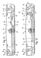
- a lever mechanism is arranged between the second functional unit associated adjusting lever 21 and the facing end of the spindle 24, a lever mechanism is arranged.
- this kinematic lever mechanism consists of two by a pin 40 articulated levers 41, 42nd
- a guide pin is formed, which is guided in a guide 43 longitudinally displaceable.
- the two levers 41, 42 of the lever mechanism In the basic position, not shown, as well as according to the illustration FIG. 12 stand the two levers 41, 42 of the lever mechanism in an approximately upright position to each other.
- the integrally formed on the lever 42 guide pin and the guide 43 are in a loose, but guided connection to each other, since the molded guide pin and the adjusting lever 21 of the second functional unit facing away arranged semi-circular end stop of the guide 43 are at a distance.
- the at least one flexible traction means 45 which may be a rope or a belt.
- the driven member of the Drehbaumreduziergetriebes 23 has a centrally disposed internally threaded bore, wherein the threads of the internally threaded bore with the external threads of the spindle 24 are engaged.
- This flexible traction means is connected at one end to the end region of the spindle 24, is then guided over a guide roller 46 mounted in the housing 11, which, based on the direction of movement of the spindle 24 in the direction of the adjusting lever 21 behind this adjusting lever 21. The other end is fixed to the sliding member 44.
- the deflecting roller 46 is rotated counterclockwise as shown and the sliding element 44 is pivoted in the direction of the adjusting lever 21, so that this also is turned. However, if only the adjusting lever to be pivoted, this movement is transmitted to the adjusting lever 21 via the lever member 44 by changing the direction of rotation of the drive motor 22 and the direction of movement of the spindle 24.
- the traction means 45 is formed such that it sags something or is provided with such an excessive length, that it is initially practically ineffective and still can not transmit forces. Now moves the spindle in the direction of the adjusting lever 20 of the first functional unit by a predetermined distance, so the traction means stretches so that the adjusting lever 21 of the second functional unit is additionally pivoted with.
- a slotted guide In the execution according to the FIGS. 14 and 15 is provided between the adjusting lever 21 and the facing end of the spindle 24 a slotted guide.
- This consists in the illustrated embodiment, essentially of a control lever 47 which is provided with a bearing journal which is displaceable in a guide 43 or is mounted stationary.
- This slide guide which can be seen as a thrust device, contains two sliding blocks 48, 49 with control grooves 50, 51, in which pins 52, 53 of the control lever 47 arranged at the end are guided.
- the guide 43 is formed as a slot-shaped pocket and inserted into the wall of the housing 11 or formed thereon.
- the journals of the control lever 47 are slidably inserted into the guide 43.
- In the basic position shown in Figure 14 are journal and the guide 43 in a loose, but guided connection to each other, since the bearing pin and the adjusting lever 21 of the second functional unit facing away from arranged semi-circular end stop of the guide 43 are at a distance.
- the speed reducer 23 facing sliding block 48 is provided with a control groove 50 to be regarded as S-shaped.
- This control groove 50 is provided at the end with parallel and spaced from the spindle 24 groove portions, wherein the central region is inclined to the spindle 24, wherein the included angle is an obtuse angle.
- the cam groove 51 of the adjusting lever 21 facing lying sliding block 49 is inclined to the spindle 24, wherein this included angle is an obtuse angle.
- This control groove 51 extends in a straight line, and has in at least one end region on a portion 51 b, which is at right angles to the spindle 24 or at right angles to the imaginary line between the pin 53 and the central longitudinal axis of the journal of the control lever 47.
- the basic position of the spindle and the control lever 43 is in the FIG. 14 shown. Thereafter, the pin 52 is in the lower, rectilinear region of the cam groove 50 approximately at the level of the spindle 24. The opposite pin 53 is located in the upper region of the cam groove 51, ie, the distance to the spindle 24 is greater than that of the pin 52. As shown FIG. 14 In another embodiment, not shown, the geometries of the sliding blocks 48, 49, however, designed such that the central longitudinal axis of the journal of the control lever 47 in the plane of the central longitudinal axis the spindle 24 is arranged. A comparison of FIGS.
- the shapes of the control grooves 50, 51 are adapted to the sequence of movements coordinated with the respective course of motion of the control lever 47.
- the sliding blocks 49, 49 are indirectly in operative connection directly or indirectly via the control lever 47 or via further components, so that when adjusting the spindle 24 in the direction of the adjusting lever 21 of the second functional unit, the second functional unit is immediately adjusted immediately, so that the adjusting lever 21 pivots. If, from the basic position, the spindle 24 is understood in the direction of the adjusting lever 20 of the first functional unit, the adjusting lever 20 of the first functional unit is then immediately adjusted immediately thereafter.
- the time-delayed actuation of the second adjusting lever 21 of the second functional unit by the sliding block 49 or with the sliding block 49 in operative connection and not shown component takes place through the contour of the control grooves 50, 51st
- Each control groove has differently formed sections 50, 51, 50a, 50b, 50c, 51a, 51b.
- individual portions 50a, 50c are arranged at a distance from each other and are parallel or approximately parallel to the central longitudinal axis of the spindle 24, while other portions 50b, 51a are rectilinear, arcuate or wavy and are at an angle to the central longitudinal axis of the spindle and the sections 50a and Connect 50b together.
- Other sections 51b of the control grooves 50, 51 are also rectilinear or arcuate and are at a right angle or at approximately right angles to the central longitudinal axis of the spindle or to the imaginary line between the pin 53 and the central longitudinal axis of the journal of the control lever 47.
- the sliding block 51 can be generated in a uniform movement of the spindle 24, so that this in a further embodiment, in addition, time-delayed completes its movement while the spindle 24 continues to move in the direction of the adjustment lift 20.
- a portion 50c of the control groove 50 which is formed parallel to the central longitudinal axis of the spindle 24 or by a portion 51b, which is arranged substantially perpendicular to the central longitudinal axis of the spindle 24 or a circular arc-like course, wherein the center of the circle substantially in the central longitudinal axis of the journal of the control lever 47 is arranged
- the double drives is equipped with a single drive motor, and that when adjusting the adjusting lever 20 of the first functional unit, preferably the backrest of a slatted base of the adjusting lever 21 of the second Function unit, preferably a foot part of a slatted frame is pivoted time-delayed. Furthermore, it is essential that only the control lever 21 of the second functional unit can be adjusted without causing a movement of the adjusting lever 20 of the first functional unit.
Landscapes
- Health & Medical Sciences (AREA)
- General Health & Medical Sciences (AREA)
- Nursing (AREA)
- Transmission Devices (AREA)
Applications Claiming Priority (2)
| Application Number | Priority Date | Filing Date | Title |
|---|---|---|---|
| DE200820016049 DE202008016049U1 (de) | 2008-12-03 | 2008-12-03 | Doppelantrieb für Möbel |
| PCT/EP2009/065457 WO2010063586A1 (de) | 2008-12-03 | 2009-11-19 | Doppelantrieb für möbel |
Publications (2)
| Publication Number | Publication Date |
|---|---|
| EP2369958A1 EP2369958A1 (de) | 2011-10-05 |
| EP2369958B1 true EP2369958B1 (de) | 2013-01-02 |
Family
ID=41785716
Family Applications (1)
| Application Number | Title | Priority Date | Filing Date |
|---|---|---|---|
| EP09756485A Not-in-force EP2369958B1 (de) | 2008-12-03 | 2009-11-19 | Doppelantrieb für möbel |
Country Status (5)
| Country | Link |
|---|---|
| EP (1) | EP2369958B1 (da) |
| DE (1) | DE202008016049U1 (da) |
| DK (1) | DK2369958T3 (da) |
| ES (1) | ES2402393T3 (da) |
| WO (1) | WO2010063586A1 (da) |
Cited By (1)
| Publication number | Priority date | Publication date | Assignee | Title |
|---|---|---|---|---|
| CN104613151A (zh) * | 2015-02-27 | 2015-05-13 | 四川昱峰医疗器械有限公司 | 一种双向丝杆装置及监护病床升降装置 |
Families Citing this family (2)
| Publication number | Priority date | Publication date | Assignee | Title |
|---|---|---|---|---|
| DE202015101318U1 (de) * | 2015-03-13 | 2016-06-14 | Dewertokin Gmbh | Elektromotorischer Möbelantrieb |
| DE202016100780U1 (de) * | 2016-02-16 | 2017-05-18 | Dewertokin Gmbh | Möbelantriebssystem |
Citations (1)
| Publication number | Priority date | Publication date | Assignee | Title |
|---|---|---|---|---|
| DE202005008336U1 (de) * | 2005-05-24 | 2006-10-05 | Cimosys Ag | Baukastensystem zur Montage motorisch verstellbarer Stützeinrichtungen für Polsterungen von Sitz- und/oder Liegemöbeln, insbesondere für Matratzen und Betten |
Family Cites Families (7)
| Publication number | Priority date | Publication date | Assignee | Title |
|---|---|---|---|---|
| DE29714746U1 (de) * | 1997-08-18 | 1997-10-09 | Dewert Antriebs- und Systemtechnik GmbH & Co KG, 32278 Kirchlengern | Als Doppelantrieb ausgebildeter elektromotorischer Möbelantrieb |
| DE20006690U1 (de) * | 2000-04-11 | 2001-08-16 | Cimosys Ag, Goldingen | Als Doppelantrieb ausgebildeter Möbelantrieb |
| DE10046750C1 (de) * | 2000-09-21 | 2002-04-18 | Cimosys Ag Goldingen | Als Doppelantrieb ausgebildeter Möbelantrieb |
| DE10138025A1 (de) * | 2001-08-08 | 2003-05-22 | Cimosys Ltd | Möbelantrieb zum Verstellen von Teilen eines Möbels relativ zueinander |
| DE20200499U1 (de) * | 2002-01-15 | 2002-05-16 | Dewert Antriebs- und Systemtechnik GmbH & Co KG, 32278 Kirchlengern | Möbelbeschlag zur Sitzhöhen- und Sitztiefenverstellung |
| DE20302139U1 (de) * | 2002-09-16 | 2003-04-24 | Dewert Antriebs- und Systemtechnik GmbH & Co KG, 32278 Kirchlengern | Elektromotorischer Möbelantrieb |
| DE102006033982B4 (de) * | 2006-07-22 | 2009-03-05 | Stabilus Gmbh | Spindelantrieb |
-
2008
- 2008-12-03 DE DE200820016049 patent/DE202008016049U1/de not_active Expired - Lifetime
-
2009
- 2009-11-19 WO PCT/EP2009/065457 patent/WO2010063586A1/de not_active Ceased
- 2009-11-19 DK DK09756485.0T patent/DK2369958T3/da active
- 2009-11-19 ES ES09756485T patent/ES2402393T3/es active Active
- 2009-11-19 EP EP09756485A patent/EP2369958B1/de not_active Not-in-force
Patent Citations (1)
| Publication number | Priority date | Publication date | Assignee | Title |
|---|---|---|---|---|
| DE202005008336U1 (de) * | 2005-05-24 | 2006-10-05 | Cimosys Ag | Baukastensystem zur Montage motorisch verstellbarer Stützeinrichtungen für Polsterungen von Sitz- und/oder Liegemöbeln, insbesondere für Matratzen und Betten |
Cited By (1)
| Publication number | Priority date | Publication date | Assignee | Title |
|---|---|---|---|---|
| CN104613151A (zh) * | 2015-02-27 | 2015-05-13 | 四川昱峰医疗器械有限公司 | 一种双向丝杆装置及监护病床升降装置 |
Also Published As
| Publication number | Publication date |
|---|---|
| DE202008016049U1 (de) | 2010-04-15 |
| DK2369958T3 (da) | 2013-04-08 |
| WO2010063586A1 (de) | 2010-06-10 |
| EP2369958A1 (de) | 2011-10-05 |
| ES2402393T3 (es) | 2013-05-03 |
Similar Documents
| Publication | Publication Date | Title |
|---|---|---|
| DE3320889C2 (da) | ||
| EP2694355B1 (de) | Elektromechanische servolenkung mit spielausgleich für das schneckenradgetriebe | |
| WO2017143377A1 (de) | Stellarmantrieb | |
| DE102012107102A1 (de) | Elektromotorischer Möbelantrieb | |
| EP2777136B1 (de) | Linearantrieb für möbel | |
| DE202005002585U1 (de) | Elektromotorischer Linearantrieb | |
| EP3752694B1 (de) | Autoparkvorrichtung | |
| DE102023115292A1 (de) | Aktor zur Bereitstellung eines Drehmoments mit einem Linearantrieb | |
| DE20311032U1 (de) | Antriebsvorrichtung | |
| WO2005110158A1 (de) | Doppelantrieb zum verstellen von teilen eines möbels | |
| EP2369958B1 (de) | Doppelantrieb für möbel | |
| DE102005007205B3 (de) | Elektromotorischer Linearantrieb | |
| DE202008016050U1 (de) | Doppelantrieb für Möbel | |
| EP2994021B1 (de) | Lattenrost mit einem elektromotorischen möbelantrieb | |
| EP3817627B1 (de) | Stuhl | |
| EP3851221B1 (de) | Rundmaschine | |
| DE4241183C2 (de) | Verstellgetriebe für zwei Verstellungen, insbesondere an einem Sitz eines Kraftfahrzeuges | |
| DE10301584B4 (de) | Vorrichtung zur verschieblichen Anordnung eines Paneels | |
| DE102014118194A1 (de) | Stellvorrichtung für einen Flügel sowie Vorrichtung zur Einstellung von mehreren Flügeln | |
| EP4174268B1 (de) | Schiebetürrollenbeschlag und zugehörige schiebetürenanordnung | |
| EP1862095B1 (de) | Möbelverstellvorrichtung | |
| CH696707A5 (de) | Verstellvorrichtung. | |
| WO1992021601A1 (de) | Legemaschine | |
| WO1994015119A1 (de) | Lineare verstelleinrichtung mit einer überlastsicherung, sowie ein treppenlift | |
| DE102004034100A1 (de) | Einrichtung zum Verstellen von mechanischen Stellgliedern |
Legal Events
| Date | Code | Title | Description |
|---|---|---|---|
| PUAI | Public reference made under article 153(3) epc to a published international application that has entered the european phase |
Free format text: ORIGINAL CODE: 0009012 |
|
| 17P | Request for examination filed |
Effective date: 20110630 |
|
| AK | Designated contracting states |
Kind code of ref document: A1 Designated state(s): AT BE BG CH CY CZ DE DK EE ES FI FR GB GR HR HU IE IS IT LI LT LU LV MC MK MT NL NO PL PT RO SE SI SK SM TR |
|
| DAX | Request for extension of the european patent (deleted) | ||
| GRAP | Despatch of communication of intention to grant a patent |
Free format text: ORIGINAL CODE: EPIDOSNIGR1 |
|
| GRAS | Grant fee paid |
Free format text: ORIGINAL CODE: EPIDOSNIGR3 |
|
| GRAP | Despatch of communication of intention to grant a patent |
Free format text: ORIGINAL CODE: EPIDOSNIGR1 |
|
| RAP1 | Party data changed (applicant data changed or rights of an application transferred) |
Owner name: DEWERTOKIN GMBH |
|
| GRAA | (expected) grant |
Free format text: ORIGINAL CODE: 0009210 |
|
| AK | Designated contracting states |
Kind code of ref document: B1 Designated state(s): AT BE BG CH CY CZ DE DK EE ES FI FR GB GR HR HU IE IS IT LI LT LU LV MC MK MT NL NO PL PT RO SE SI SK SM TR |
|
| REG | Reference to a national code |
Ref country code: GB Ref legal event code: FG4D Free format text: NOT ENGLISH |
|
| REG | Reference to a national code |
Ref country code: AT Ref legal event code: REF Ref document number: 591093 Country of ref document: AT Kind code of ref document: T Effective date: 20130115 Ref country code: CH Ref legal event code: EP |
|
| REG | Reference to a national code |
Ref country code: IE Ref legal event code: FG4D Free format text: LANGUAGE OF EP DOCUMENT: GERMAN |
|
| REG | Reference to a national code |
Ref country code: DE Ref legal event code: R096 Ref document number: 502009005894 Country of ref document: DE Effective date: 20130314 |
|
| REG | Reference to a national code |
Ref country code: DK Ref legal event code: T3 |
|
| REG | Reference to a national code |
Ref country code: SE Ref legal event code: TRGR |
|
| REG | Reference to a national code |
Ref country code: NL Ref legal event code: T3 |
|
| REG | Reference to a national code |
Ref country code: ES Ref legal event code: FG2A Ref document number: 2402393 Country of ref document: ES Kind code of ref document: T3 Effective date: 20130503 |
|
| PG25 | Lapsed in a contracting state [announced via postgrant information from national office to epo] |
Ref country code: SI Free format text: LAPSE BECAUSE OF FAILURE TO SUBMIT A TRANSLATION OF THE DESCRIPTION OR TO PAY THE FEE WITHIN THE PRESCRIBED TIME-LIMIT Effective date: 20130102 |
|
| REG | Reference to a national code |
Ref country code: LT Ref legal event code: MG4D |
|
| PG25 | Lapsed in a contracting state [announced via postgrant information from national office to epo] |
Ref country code: BG Free format text: LAPSE BECAUSE OF FAILURE TO SUBMIT A TRANSLATION OF THE DESCRIPTION OR TO PAY THE FEE WITHIN THE PRESCRIBED TIME-LIMIT Effective date: 20130402 Ref country code: CZ Free format text: LAPSE BECAUSE OF FAILURE TO SUBMIT A TRANSLATION OF THE DESCRIPTION OR TO PAY THE FEE WITHIN THE PRESCRIBED TIME-LIMIT Effective date: 20130102 Ref country code: NO Free format text: LAPSE BECAUSE OF FAILURE TO SUBMIT A TRANSLATION OF THE DESCRIPTION OR TO PAY THE FEE WITHIN THE PRESCRIBED TIME-LIMIT Effective date: 20130402 Ref country code: IS Free format text: LAPSE BECAUSE OF FAILURE TO SUBMIT A TRANSLATION OF THE DESCRIPTION OR TO PAY THE FEE WITHIN THE PRESCRIBED TIME-LIMIT Effective date: 20130502 Ref country code: LT Free format text: LAPSE BECAUSE OF FAILURE TO SUBMIT A TRANSLATION OF THE DESCRIPTION OR TO PAY THE FEE WITHIN THE PRESCRIBED TIME-LIMIT Effective date: 20130102 |
|
| PG25 | Lapsed in a contracting state [announced via postgrant information from national office to epo] |
Ref country code: LV Free format text: LAPSE BECAUSE OF FAILURE TO SUBMIT A TRANSLATION OF THE DESCRIPTION OR TO PAY THE FEE WITHIN THE PRESCRIBED TIME-LIMIT Effective date: 20130102 Ref country code: GR Free format text: LAPSE BECAUSE OF FAILURE TO SUBMIT A TRANSLATION OF THE DESCRIPTION OR TO PAY THE FEE WITHIN THE PRESCRIBED TIME-LIMIT Effective date: 20130403 Ref country code: PT Free format text: LAPSE BECAUSE OF FAILURE TO SUBMIT A TRANSLATION OF THE DESCRIPTION OR TO PAY THE FEE WITHIN THE PRESCRIBED TIME-LIMIT Effective date: 20130502 Ref country code: PL Free format text: LAPSE BECAUSE OF FAILURE TO SUBMIT A TRANSLATION OF THE DESCRIPTION OR TO PAY THE FEE WITHIN THE PRESCRIBED TIME-LIMIT Effective date: 20130102 Ref country code: FI Free format text: LAPSE BECAUSE OF FAILURE TO SUBMIT A TRANSLATION OF THE DESCRIPTION OR TO PAY THE FEE WITHIN THE PRESCRIBED TIME-LIMIT Effective date: 20130102 |
|
| PG25 | Lapsed in a contracting state [announced via postgrant information from national office to epo] |
Ref country code: HR Free format text: LAPSE BECAUSE OF FAILURE TO SUBMIT A TRANSLATION OF THE DESCRIPTION OR TO PAY THE FEE WITHIN THE PRESCRIBED TIME-LIMIT Effective date: 20130102 |
|
| PG25 | Lapsed in a contracting state [announced via postgrant information from national office to epo] |
Ref country code: EE Free format text: LAPSE BECAUSE OF FAILURE TO SUBMIT A TRANSLATION OF THE DESCRIPTION OR TO PAY THE FEE WITHIN THE PRESCRIBED TIME-LIMIT Effective date: 20130102 Ref country code: RO Free format text: LAPSE BECAUSE OF FAILURE TO SUBMIT A TRANSLATION OF THE DESCRIPTION OR TO PAY THE FEE WITHIN THE PRESCRIBED TIME-LIMIT Effective date: 20130102 Ref country code: SK Free format text: LAPSE BECAUSE OF FAILURE TO SUBMIT A TRANSLATION OF THE DESCRIPTION OR TO PAY THE FEE WITHIN THE PRESCRIBED TIME-LIMIT Effective date: 20130102 |
|
| PLBE | No opposition filed within time limit |
Free format text: ORIGINAL CODE: 0009261 |
|
| STAA | Information on the status of an ep patent application or granted ep patent |
Free format text: STATUS: NO OPPOSITION FILED WITHIN TIME LIMIT |
|
| PG25 | Lapsed in a contracting state [announced via postgrant information from national office to epo] |
Ref country code: CY Free format text: LAPSE BECAUSE OF FAILURE TO SUBMIT A TRANSLATION OF THE DESCRIPTION OR TO PAY THE FEE WITHIN THE PRESCRIBED TIME-LIMIT Effective date: 20130102 |
|
| 26N | No opposition filed |
Effective date: 20131003 |
|
| REG | Reference to a national code |
Ref country code: DE Ref legal event code: R097 Ref document number: 502009005894 Country of ref document: DE Effective date: 20131003 |
|
| BERE | Be: lapsed |
Owner name: DEWERTOKIN G.M.B.H. Effective date: 20131130 |
|
| REG | Reference to a national code |
Ref country code: CH Ref legal event code: PL |
|
| PG25 | Lapsed in a contracting state [announced via postgrant information from national office to epo] |
Ref country code: MC Free format text: LAPSE BECAUSE OF FAILURE TO SUBMIT A TRANSLATION OF THE DESCRIPTION OR TO PAY THE FEE WITHIN THE PRESCRIBED TIME-LIMIT Effective date: 20130102 Ref country code: LI Free format text: LAPSE BECAUSE OF NON-PAYMENT OF DUE FEES Effective date: 20131130 Ref country code: CH Free format text: LAPSE BECAUSE OF NON-PAYMENT OF DUE FEES Effective date: 20131130 |
|
| REG | Reference to a national code |
Ref country code: IE Ref legal event code: MM4A |
|
| PG25 | Lapsed in a contracting state [announced via postgrant information from national office to epo] |
Ref country code: BE Free format text: LAPSE BECAUSE OF NON-PAYMENT OF DUE FEES Effective date: 20131130 |
|
| PG25 | Lapsed in a contracting state [announced via postgrant information from national office to epo] |
Ref country code: IE Free format text: LAPSE BECAUSE OF NON-PAYMENT OF DUE FEES Effective date: 20131119 |
|
| PG25 | Lapsed in a contracting state [announced via postgrant information from national office to epo] |
Ref country code: SM Free format text: LAPSE BECAUSE OF FAILURE TO SUBMIT A TRANSLATION OF THE DESCRIPTION OR TO PAY THE FEE WITHIN THE PRESCRIBED TIME-LIMIT Effective date: 20130102 |
|
| PG25 | Lapsed in a contracting state [announced via postgrant information from national office to epo] |
Ref country code: TR Free format text: LAPSE BECAUSE OF FAILURE TO SUBMIT A TRANSLATION OF THE DESCRIPTION OR TO PAY THE FEE WITHIN THE PRESCRIBED TIME-LIMIT Effective date: 20130102 |
|
| PG25 | Lapsed in a contracting state [announced via postgrant information from national office to epo] |
Ref country code: MK Free format text: LAPSE BECAUSE OF FAILURE TO SUBMIT A TRANSLATION OF THE DESCRIPTION OR TO PAY THE FEE WITHIN THE PRESCRIBED TIME-LIMIT Effective date: 20130102 Ref country code: HU Free format text: LAPSE BECAUSE OF FAILURE TO SUBMIT A TRANSLATION OF THE DESCRIPTION OR TO PAY THE FEE WITHIN THE PRESCRIBED TIME-LIMIT; INVALID AB INITIO Effective date: 20091119 Ref country code: LU Free format text: LAPSE BECAUSE OF NON-PAYMENT OF DUE FEES Effective date: 20131119 |
|
| PG25 | Lapsed in a contracting state [announced via postgrant information from national office to epo] |
Ref country code: MT Free format text: LAPSE BECAUSE OF FAILURE TO SUBMIT A TRANSLATION OF THE DESCRIPTION OR TO PAY THE FEE WITHIN THE PRESCRIBED TIME-LIMIT Effective date: 20130102 |
|
| REG | Reference to a national code |
Ref country code: FR Ref legal event code: PLFP Year of fee payment: 7 |
|
| REG | Reference to a national code |
Ref country code: AT Ref legal event code: MM01 Ref document number: 591093 Country of ref document: AT Kind code of ref document: T Effective date: 20141119 |
|
| PGFP | Annual fee paid to national office [announced via postgrant information from national office to epo] |
Ref country code: DK Payment date: 20151124 Year of fee payment: 7 Ref country code: GB Payment date: 20151123 Year of fee payment: 7 |
|
| PG25 | Lapsed in a contracting state [announced via postgrant information from national office to epo] |
Ref country code: AT Free format text: LAPSE BECAUSE OF NON-PAYMENT OF DUE FEES Effective date: 20141119 |
|
| PGFP | Annual fee paid to national office [announced via postgrant information from national office to epo] |
Ref country code: ES Payment date: 20151124 Year of fee payment: 7 Ref country code: SE Payment date: 20151123 Year of fee payment: 7 Ref country code: NL Payment date: 20151124 Year of fee payment: 7 |
|
| REG | Reference to a national code |
Ref country code: FR Ref legal event code: PLFP Year of fee payment: 8 |
|
| REG | Reference to a national code |
Ref country code: DK Ref legal event code: EBP Effective date: 20161130 |
|
| REG | Reference to a national code |
Ref country code: SE Ref legal event code: EUG |
|
| REG | Reference to a national code |
Ref country code: NL Ref legal event code: MM Effective date: 20161201 |
|
| GBPC | Gb: european patent ceased through non-payment of renewal fee |
Effective date: 20161119 |
|
| PG25 | Lapsed in a contracting state [announced via postgrant information from national office to epo] |
Ref country code: SE Free format text: LAPSE BECAUSE OF NON-PAYMENT OF DUE FEES Effective date: 20161120 |
|
| PG25 | Lapsed in a contracting state [announced via postgrant information from national office to epo] |
Ref country code: NL Free format text: LAPSE BECAUSE OF NON-PAYMENT OF DUE FEES Effective date: 20161201 |
|
| REG | Reference to a national code |
Ref country code: FR Ref legal event code: PLFP Year of fee payment: 9 |
|
| PG25 | Lapsed in a contracting state [announced via postgrant information from national office to epo] |
Ref country code: DK Free format text: LAPSE BECAUSE OF NON-PAYMENT OF DUE FEES Effective date: 20161130 Ref country code: GB Free format text: LAPSE BECAUSE OF NON-PAYMENT OF DUE FEES Effective date: 20161119 |
|
| PG25 | Lapsed in a contracting state [announced via postgrant information from national office to epo] |
Ref country code: ES Free format text: LAPSE BECAUSE OF NON-PAYMENT OF DUE FEES Effective date: 20161120 |
|
| REG | Reference to a national code |
Ref country code: ES Ref legal event code: FD2A Effective date: 20181116 |
|
| PGFP | Annual fee paid to national office [announced via postgrant information from national office to epo] |
Ref country code: FR Payment date: 20181127 Year of fee payment: 10 Ref country code: IT Payment date: 20181122 Year of fee payment: 10 |
|
| PG25 | Lapsed in a contracting state [announced via postgrant information from national office to epo] |
Ref country code: IT Free format text: LAPSE BECAUSE OF NON-PAYMENT OF DUE FEES Effective date: 20191119 Ref country code: FR Free format text: LAPSE BECAUSE OF NON-PAYMENT OF DUE FEES Effective date: 20191130 |
|
| REG | Reference to a national code |
Ref country code: DE Ref legal event code: R082 Ref document number: 502009005894 Country of ref document: DE Representative=s name: PATENT- UND RECHTSANWAELTE LOESENBECK, SPECHT,, DE Ref country code: DE Ref legal event code: R081 Ref document number: 502009005894 Country of ref document: DE Owner name: DEWERTOKIN TECHNOLOGY GROUP CO., LTD., JIAXING, CN Free format text: FORMER OWNER: DEWERTOKIN GMBH, 32278 KIRCHLENGERN, DE |
|
| PGFP | Annual fee paid to national office [announced via postgrant information from national office to epo] |
Ref country code: DE Payment date: 20201218 Year of fee payment: 12 |
|
| REG | Reference to a national code |
Ref country code: DE Ref legal event code: R119 Ref document number: 502009005894 Country of ref document: DE |
|
| PG25 | Lapsed in a contracting state [announced via postgrant information from national office to epo] |
Ref country code: DE Free format text: LAPSE BECAUSE OF NON-PAYMENT OF DUE FEES Effective date: 20220601 |