EP2369343B1 - Device and method for manipulating or examining a liquid sample - Google Patents
Device and method for manipulating or examining a liquid sample Download PDFInfo
- Publication number
- EP2369343B1 EP2369343B1 EP20100002685 EP10002685A EP2369343B1 EP 2369343 B1 EP2369343 B1 EP 2369343B1 EP 20100002685 EP20100002685 EP 20100002685 EP 10002685 A EP10002685 A EP 10002685A EP 2369343 B1 EP2369343 B1 EP 2369343B1
- Authority
- EP
- European Patent Office
- Prior art keywords
- channel
- carrier
- sample
- detection
- support
- Prior art date
- Legal status (The legal status is an assumption and is not a legal conclusion. Google has not performed a legal analysis and makes no representation as to the accuracy of the status listed.)
- Active
Links
Images


Classifications
-
- B—PERFORMING OPERATIONS; TRANSPORTING
- B01—PHYSICAL OR CHEMICAL PROCESSES OR APPARATUS IN GENERAL
- B01L—CHEMICAL OR PHYSICAL LABORATORY APPARATUS FOR GENERAL USE
- B01L3/00—Containers or dishes for laboratory use, e.g. laboratory glassware; Droppers
- B01L3/50—Containers for the purpose of retaining a material to be analysed, e.g. test tubes
- B01L3/502—Containers for the purpose of retaining a material to be analysed, e.g. test tubes with fluid transport, e.g. in multi-compartment structures
- B01L3/5027—Containers for the purpose of retaining a material to be analysed, e.g. test tubes with fluid transport, e.g. in multi-compartment structures by integrated microfluidic structures, i.e. dimensions of channels and chambers are such that surface tension forces are important, e.g. lab-on-a-chip
-
- F—MECHANICAL ENGINEERING; LIGHTING; HEATING; WEAPONS; BLASTING
- F16—ENGINEERING ELEMENTS AND UNITS; GENERAL MEASURES FOR PRODUCING AND MAINTAINING EFFECTIVE FUNCTIONING OF MACHINES OR INSTALLATIONS; THERMAL INSULATION IN GENERAL
- F16K—VALVES; TAPS; COCKS; ACTUATING-FLOATS; DEVICES FOR VENTING OR AERATING
- F16K99/00—Subject matter not provided for in other groups of this subclass
- F16K99/0001—Microvalves
- F16K99/0003—Constructional types of microvalves; Details of the cutting-off member
- F16K99/0017—Capillary or surface tension valves, e.g. using electro-wetting or electro-capillarity effects
-
- B—PERFORMING OPERATIONS; TRANSPORTING
- B01—PHYSICAL OR CHEMICAL PROCESSES OR APPARATUS IN GENERAL
- B01L—CHEMICAL OR PHYSICAL LABORATORY APPARATUS FOR GENERAL USE
- B01L3/00—Containers or dishes for laboratory use, e.g. laboratory glassware; Droppers
- B01L3/50—Containers for the purpose of retaining a material to be analysed, e.g. test tubes
- B01L3/502—Containers for the purpose of retaining a material to be analysed, e.g. test tubes with fluid transport, e.g. in multi-compartment structures
- B01L3/5027—Containers for the purpose of retaining a material to be analysed, e.g. test tubes with fluid transport, e.g. in multi-compartment structures by integrated microfluidic structures, i.e. dimensions of channels and chambers are such that surface tension forces are important, e.g. lab-on-a-chip
- B01L3/50273—Containers for the purpose of retaining a material to be analysed, e.g. test tubes with fluid transport, e.g. in multi-compartment structures by integrated microfluidic structures, i.e. dimensions of channels and chambers are such that surface tension forces are important, e.g. lab-on-a-chip characterised by the means or forces applied to move the fluids
-
- B—PERFORMING OPERATIONS; TRANSPORTING
- B01—PHYSICAL OR CHEMICAL PROCESSES OR APPARATUS IN GENERAL
- B01L—CHEMICAL OR PHYSICAL LABORATORY APPARATUS FOR GENERAL USE
- B01L3/00—Containers or dishes for laboratory use, e.g. laboratory glassware; Droppers
- B01L3/50—Containers for the purpose of retaining a material to be analysed, e.g. test tubes
- B01L3/502—Containers for the purpose of retaining a material to be analysed, e.g. test tubes with fluid transport, e.g. in multi-compartment structures
- B01L3/5027—Containers for the purpose of retaining a material to be analysed, e.g. test tubes with fluid transport, e.g. in multi-compartment structures by integrated microfluidic structures, i.e. dimensions of channels and chambers are such that surface tension forces are important, e.g. lab-on-a-chip
- B01L3/502769—Containers for the purpose of retaining a material to be analysed, e.g. test tubes with fluid transport, e.g. in multi-compartment structures by integrated microfluidic structures, i.e. dimensions of channels and chambers are such that surface tension forces are important, e.g. lab-on-a-chip characterised by multiphase flow arrangements
-
- G—PHYSICS
- G01—MEASURING; TESTING
- G01N—INVESTIGATING OR ANALYSING MATERIALS BY DETERMINING THEIR CHEMICAL OR PHYSICAL PROPERTIES
- G01N33/00—Investigating or analysing materials by specific methods not covered by groups G01N1/00 - G01N31/00
- G01N33/48—Biological material, e.g. blood, urine; Haemocytometers
- G01N33/50—Chemical analysis of biological material, e.g. blood, urine; Testing involving biospecific ligand binding methods; Immunological testing
- G01N33/53—Immunoassay; Biospecific binding assay; Materials therefor
- G01N33/5302—Apparatus specially adapted for immunological test procedures
- G01N33/5304—Reaction vessels, e.g. agglutination plates
-
- G—PHYSICS
- G01—MEASURING; TESTING
- G01N—INVESTIGATING OR ANALYSING MATERIALS BY DETERMINING THEIR CHEMICAL OR PHYSICAL PROPERTIES
- G01N33/00—Investigating or analysing materials by specific methods not covered by groups G01N1/00 - G01N31/00
- G01N33/48—Biological material, e.g. blood, urine; Haemocytometers
- G01N33/50—Chemical analysis of biological material, e.g. blood, urine; Testing involving biospecific ligand binding methods; Immunological testing
- G01N33/53—Immunoassay; Biospecific binding assay; Materials therefor
- G01N33/543—Immunoassay; Biospecific binding assay; Materials therefor with an insoluble carrier for immobilising immunochemicals
- G01N33/54313—Immunoassay; Biospecific binding assay; Materials therefor with an insoluble carrier for immobilising immunochemicals the carrier being characterised by its particulate form
- G01N33/54326—Magnetic particles
-
- G—PHYSICS
- G01—MEASURING; TESTING
- G01N—INVESTIGATING OR ANALYSING MATERIALS BY DETERMINING THEIR CHEMICAL OR PHYSICAL PROPERTIES
- G01N33/00—Investigating or analysing materials by specific methods not covered by groups G01N1/00 - G01N31/00
- G01N33/48—Biological material, e.g. blood, urine; Haemocytometers
- G01N33/50—Chemical analysis of biological material, e.g. blood, urine; Testing involving biospecific ligand binding methods; Immunological testing
- G01N33/53—Immunoassay; Biospecific binding assay; Materials therefor
- G01N33/543—Immunoassay; Biospecific binding assay; Materials therefor with an insoluble carrier for immobilising immunochemicals
- G01N33/54366—Apparatus specially adapted for solid-phase testing
-
- B—PERFORMING OPERATIONS; TRANSPORTING
- B01—PHYSICAL OR CHEMICAL PROCESSES OR APPARATUS IN GENERAL
- B01L—CHEMICAL OR PHYSICAL LABORATORY APPARATUS FOR GENERAL USE
- B01L2200/00—Solutions for specific problems relating to chemical or physical laboratory apparatus
- B01L2200/06—Fluid handling related problems
- B01L2200/0647—Handling flowable solids, e.g. microscopic beads, cells, particles
-
- B—PERFORMING OPERATIONS; TRANSPORTING
- B01—PHYSICAL OR CHEMICAL PROCESSES OR APPARATUS IN GENERAL
- B01L—CHEMICAL OR PHYSICAL LABORATORY APPARATUS FOR GENERAL USE
- B01L2300/00—Additional constructional details
- B01L2300/06—Auxiliary integrated devices, integrated components
- B01L2300/0627—Sensor or part of a sensor is integrated
- B01L2300/0636—Integrated biosensor, microarrays
-
- B—PERFORMING OPERATIONS; TRANSPORTING
- B01—PHYSICAL OR CHEMICAL PROCESSES OR APPARATUS IN GENERAL
- B01L—CHEMICAL OR PHYSICAL LABORATORY APPARATUS FOR GENERAL USE
- B01L2400/00—Moving or stopping fluids
- B01L2400/04—Moving fluids with specific forces or mechanical means
- B01L2400/0403—Moving fluids with specific forces or mechanical means specific forces
- B01L2400/043—Moving fluids with specific forces or mechanical means specific forces magnetic forces
-
- B—PERFORMING OPERATIONS; TRANSPORTING
- B01—PHYSICAL OR CHEMICAL PROCESSES OR APPARATUS IN GENERAL
- B01L—CHEMICAL OR PHYSICAL LABORATORY APPARATUS FOR GENERAL USE
- B01L2400/00—Moving or stopping fluids
- B01L2400/04—Moving fluids with specific forces or mechanical means
- B01L2400/0475—Moving fluids with specific forces or mechanical means specific mechanical means and fluid pressure
-
- B—PERFORMING OPERATIONS; TRANSPORTING
- B01—PHYSICAL OR CHEMICAL PROCESSES OR APPARATUS IN GENERAL
- B01L—CHEMICAL OR PHYSICAL LABORATORY APPARATUS FOR GENERAL USE
- B01L2400/00—Moving or stopping fluids
- B01L2400/06—Valves, specific forms thereof
- B01L2400/0688—Valves, specific forms thereof surface tension valves, capillary stop, capillary break
-
- Y—GENERAL TAGGING OF NEW TECHNOLOGICAL DEVELOPMENTS; GENERAL TAGGING OF CROSS-SECTIONAL TECHNOLOGIES SPANNING OVER SEVERAL SECTIONS OF THE IPC; TECHNICAL SUBJECTS COVERED BY FORMER USPC CROSS-REFERENCE ART COLLECTIONS [XRACs] AND DIGESTS
- Y10—TECHNICAL SUBJECTS COVERED BY FORMER USPC
- Y10T—TECHNICAL SUBJECTS COVERED BY FORMER US CLASSIFICATION
- Y10T137/00—Fluid handling
- Y10T137/206—Flow affected by fluid contact, energy field or coanda effect [e.g., pure fluid device or system]
- Y10T137/218—Means to regulate or vary operation of device
- Y10T137/2202—By movable element
- Y10T137/2218—Means [e.g., valve] in control input
-
- Y—GENERAL TAGGING OF NEW TECHNOLOGICAL DEVELOPMENTS; GENERAL TAGGING OF CROSS-SECTIONAL TECHNOLOGIES SPANNING OVER SEVERAL SECTIONS OF THE IPC; TECHNICAL SUBJECTS COVERED BY FORMER USPC CROSS-REFERENCE ART COLLECTIONS [XRACs] AND DIGESTS
- Y10—TECHNICAL SUBJECTS COVERED BY FORMER USPC
- Y10T—TECHNICAL SUBJECTS COVERED BY FORMER US CLASSIFICATION
- Y10T137/00—Fluid handling
- Y10T137/206—Flow affected by fluid contact, energy field or coanda effect [e.g., pure fluid device or system]
- Y10T137/2224—Structure of body of device
Definitions
- the present invention relates to a device for manipulating and / or examining a liquid sample according to the preamble of claim 1.
- the present invention is concerned in particular with the diagnostics of microfluidic samples, particularly preferably so-called point-off-care systems (POC systems).
- the present invention is concerned with preferably miniaturized immunoassays, that is the study of samples using antibodies.
- the present invention particularly preferably relates to so-called cartridge concepts, ie small, in particular card-type, devices for the manipulation and / or examination of a liquid sample or realization of immunoassays.
- the US 2009/0227044 A1 discloses a device with a microchannel in which magnetic, luminescent nanoparticles serve as carriers for antibodies and as an internal luminescence standard.
- the carriers are vibrated by an external magnetic field generated by electromagnets to achieve better diffusion during an incubation step. Further, the electromagnets are used to hold the particles in the channel for wash and luminescence measurements.
- the WO 99/49319 A1 discloses a microsystem for manipulating magnetic particles.
- the particles are coated with a reagent or antibody and moved by magnetic forces in the microfluidic system. Different particles can be provided with different reagents.
- the evaluation is carried out magnetically and / or by fluorescence measurement.
- the US 2002/0064866 A1 discloses fibrous spherical particles as carriers of substances for carrying out tests. For this purpose, substances are bound to the fissured surface of the particles or in their surface stored. The particles are grown as a suspension and held on demand by magnetic forces.
- the US Pat. No. 7,105,357 B1 discloses a method with a pipette for generating minute droplets, wherein substances are bound to magnetic particles and these are held in the pipette by means of permanent magnets.
- the US 5,135,720 A discloses a reaction vessel with a spherical support having a magnetic core and a coating on which proteins or peptides can be attached.
- the carrier is levitated by electromagnets and a regulating mechanism to improve the efficiency of an Edman reaction with substances on the surface of the carrier.
- the US 5,439,650 A discloses a similar device wherein a portion of the reaction vessel is slidable with the floating support and the electromagnet associated therewith.
- the WO 2007/089564 A2 relates to a microchannel for examining samples.
- the channel has external electromagnets and inside the channel magnetic or luminescent nanoparticles as a carrier for antibodies.
- a manipulating device allows the carriers to move out of the sample.
- a microfluidic system In the DE 10 2004 062 534 A1 a microfluidic system is described.
- the system has particle fractions with fixed biomolecules that are guided serially and directionally through channels.
- a magnetic field can be applied.
- Karle et al. ( Karle, M; Miwa, Junichi; Roth, Günter; Haeberle, Stefan; Zengerle, Roland; von Stetten, Felix: “Continuously working microfluidic plate Form for purifying biomolecules "VDE Verlag GmbH, PAPER 31, 12 October 2009 (2009-10-12), pages 1 to 4, XP002590553 Berlin Offenbach ISBN: 978-3-8007-3183-1 ) relates to a microfluidic platform for the purification of biomolecules.
- the platform has channels and a rotatable permanent magnet acting on the platform. Magnetic beads moving in small filaments along magnetic lines transport biomolecules to be purified through the channels.
- a separation chamber receives purified DNA with beads, with the liquid being eluted through an outlet.
- the plurality of small magnetic, substantially spherical or other undefined shape particles does not allow optimal manipulation or examination of a liquid sample.
- no optimal optical detection of the binding of analytes or complexes to the carrier particles is possible.
- the object of the present invention is to provide a device and a method for manipulating and / or examining a liquid sample, in particular in a microfluidic system or channel, wherein optimized manipulation or examination and / or improved, preferably optical detection - in particular for Proof of a reaction or for the determination of an analyte - is or will be made possible and / or wherein several examinations can be performed in parallel on a sample under defined conditions and / or spatially separated.
- microfluidic is to be understood as meaning volumes of preferably less than 10 ml, more preferably less than 1 ml, and / or channel or liquid cross-sections (maximum diameter) of preferably less than 2 mm, particularly preferably less than 500 ⁇ m ,
- a carrier which is movable in a preferably microfluidic channel or system and has at least one detection or binding region for a substance is used.
- This may be an analyte of the sample or a complex formed therefrom or its dependent reaction product and / or a reagent that interacts or binds with the sample, an analyte of the sample, a complex thereof or the like.
- the reagent may interact or bind with a complex of the analyte or with an analyte-dependent reaction product.
- the reagent itself is fixed or immobilized in or on the detection or binding region.
- the detection or binding region may contain or have an immobilized antibody which interacts with an analyte of the sample or a complex containing the analyte, particularly preferably binds.
- the reagent is formed by the antibody, which interacts indirectly with the analyte, namely with a complex containing the analyte or the like.
- the term "interacting" is preferably to be understood in a broad sense in the present invention.
- the carrier is at least substantially flat or plate-shaped and / or in particular provided with an at least substantially flat or flat upper side with the detection or binding region. This is conducive to good or defined detection or determination of an analyte.
- the carrier is guided in a defined orientation in or from the channel.
- the carrier is not reversible in the channel, but preferably has a flat side and / or its side containing the detection or binding area to a side (in particular flat side) of the device or of the channel. This allows a particularly good, in particular optical detection of the latter side and thus simplifies the structure of the device or the detection in general.
- the carrier has a length that is greater than the maximum cross-section of the channel. This allows a much more defined movement and / or orientation of the carrier in the channel or microfluidic system than in the prior art. Thus, a much more defined process flow and / or a better or more defined, in particular optical detection can take place.
- the carrier fills the cross-section of the channel to more than 30%, preferably more than 40%, in particular more than 50% in terms of area.
- the carrier is formed dimensionally stable with a defined shape. This in turn is conducive to defined detection.
- only a single carrier is provided for detection and / or in the channel. This is conducive to defined detection.
- the carrier in particular by means of a manipulation device, is movable out of the sample, in particular in a gas space, or over or through a phase boundary. This in turn is conducive to a particular optical detection.
- detection in the present invention is preferably understood to mean the detection of an interaction, modification or reaction in the detection or binding region and / or the binding of a substance, such as an analyte, complex or the like, in the detection or binding region in order to allow a preferably qualitative and / or quantitative examination of the sample, in particular a qualitative and / or quantitative determination of at least one analyte of the sample.
- the detection can be carried out in particular optically, particularly preferably by luminescence or fluorescence measurement.
- the carrier is designed as a plastic part and / or injection molded part. This allows a simple, cost-effective production and / or the realization of defined properties and / or a facilitation of mass production.
- the detection or binding region is at least partially microstructured.
- microstructuring is preferably a particularly repeating structure and / or a structure having an average structure width of 10 nm to 500 .mu.m, preferably less than 10 .mu.m, and / or with elevations or depressions of 10 nm to 500 .mu.m, preferably less than 10 ⁇ m, to understand.
- the microstructuring serves to increase the surface area and / or facilitates the binding of a substance, such as an analyte or reagent, in particular an antibody or the like, in the detection or binding region.
- the carrier may be movable into different liquids, for example from the liquid sample to another liquid or vice versa, and / or optionally into different reaction chambers. This in turn is conducive to an optimized reaction procedure, an optimized sequence of different steps and / or an optimized detection.
- the carrier is moved out of the sample into a gas space of the system for detecting a substance bound in the detection or binding region.
- This allows an optimized, in particular optical detection, particularly preferably by means of luminescence or fluorescence measurement.
- the support 4 can be moved through the gas space, into a liquid other than the sample, or vice versa.
- steps such as incubation steps, washing steps or the like, in particular with minimal liquid volumes can be realized.
- Fig. 1 shows a schematic plan view of a device according to the present invention 1 for manipulating or examining a liquid sample 2.
- the device 1 is preferably at least substantially card-like, plate-like, flat, thin and / or flat.
- the device 1 preferably has (at least) one in particular microfluidic channel 3 for receiving the sample 2.
- the channel 3 or the device 1 forms in particular a microfluidic system or a part thereof.
- the device 1 preferably comprises a base part 1A, in which the channel 3 or the microfluidic system in particular by one or more depressions - preferably in the form of a groove or a plurality of grooves - is or are covered by a cover 1B is or are.
- the base part 1A is preferably formed as a plastic part and / or injection molded part.
- the base part 1A is preferably at least substantially flat, flat, plate-like and / or rigid.
- the channel 3 or the microfluidic system is preferably formed in or along a flat side of the base part 1A and / or open to a flat side.
- the channel 3 or the recess or flat side is preferably at least substantially completely covered by the cover 1B.
- other constructive solutions are also possible.
- the lid 1B is preferably formed as a film.
- the lid 1B is preferably glued or laminated and / or welded.
- the lid 1B is formed by an adhesive sheet or heat-sealing foil or the like.
- the cover 1B is preferably designed to be transparent, at least in some areas, in particular in order to enable optical detection, as described in more detail below.
- the device 1 has at least one carrier 4 movable in the channel 3 or system and / or in the sample 2.
- the carrier 4 is preferably movable into the sample 2 and / or movable within the sample 2 as indicated by the dashed position A in FIG Fig. 1 in particular, in order to enable an examination or interaction with the sample 2 or components of the sample 2, such as an analyte.
- the carrier 4 is out of the sample 2 - in the representation example according to Fig. 1 into another area of the channel 3 or system - movable, as indicated by position B,
- the carrier 4 preferably has at least one detection or binding region 5, in the representation example two or more detection or binding regions 5.
- the function of the detection or binding region 5 or the detection or binding regions 5 will be explained in more detail below, with particular reference to FIGS Fig. 2 Reference is made, which shows the device 1 in a schematic longitudinal section in position B.
- Each detection or binding region 5 preferably interacts only with one substance.
- the substance is preferably an analyte of sample 2 or a product derived therefrom or dependent, such as a complex or a complex, or a reagent that interacts or binds with the analyte or product dependent thereon.
- a detection or binding region 5 serves to bind a specific substance, such as a component or analyte of the sample 2 and / or a complex 6 formed therefrom, and / or the binding of a reagent to the sample 2 or a component or Analyte of sample 2 or complex 6 formed therefrom interacts.
- the reagent or substance according to the illustrative example is particularly preferably one or more, possibly also different, antibodies 7 which interact or bind with an analyte or a complex 6 or other product of the analyte.
- the detection or binding region 5 is formed or covered by immobilized antibodies 7.
- detection region in the present invention is preferably understood to be very general in that it interacts directly or indirectly (e.g., after pretreatment or application of antibodies 7) with the substance, particularly an analyte.
- the interaction may be a reaction, a binding, a complex formation, an adhesion, an attachment, a catalytic effect or any combination thereof.
- the support 4 preferably has a plurality of detection or binding regions 5, which are spatially separated from one another, which interact in particular with different substances or serve to determine different analytes of the sample 2, as indicated in the illustration example.
- the proposed device 1 and the proposed method are therefore preferably used to examine or diagnose the sample 2, in particular the qualitative and / or quantitative determination of at least one analyte of the sample 2.
- an immunoassay is realized, particularly preferably as a sandwich immunoassay.
- other reactions may be run or other substances, reaction products, properties or the like may be determined or measured or detected.
- the proposed device 1 and the proposed method for manipulating the sample 2 in particular by moving the carrier 4 within the sample 2 and / or by moving out of the carrier 4 from the sample 2 and / or Hineinbe admire the carrier 4 in the Sample 2 can be used.
- a mixing of the sample 2 or a transfer of a certain amount of the sample 2 or a component of the sample 2 can be realized.
- by moving the carrier 4, a transfer to the sample is possible.
- the device 1 preferably has a manipulating device 8.
- the manipulation device 8 may be the device 1 but also be assigned, in particular form part of a test device, as explained later.
- the movement of the carrier 4 takes place in the illustrated embodiment, preferably magnetically, in particular by varying a force acting on the carrier 4 magnetic field M.
- the magnetic field M is generated externally.
- the manipulation device 8 for this purpose has at least one external magnet and / or electromagnet or a plurality of electromagnets, as in FIG Fig. 2 implied
- the carrier 4 is at least partially made of magnetic or magnetizable material or provided therewith, which in particular forms a magnet 9, as in Fig. 2 In particular, this is a paramagnetic, superparamagnetic or ferromagnetic material.
- the magnetic material or the magnet 9 can be accommodated, for example, in the carrier 4, as in FIG Fig. 2 indicated, or glued or attached thereto or glued or, for example, be poured into it.
- the carrier 4 may also be made at least substantially of magnetic or magnetizable material. If necessary, several or different magnetic materials or magnets 9 on the support 4 - for example, spatially distributed or spaced from each other - are attached or used, in particular to achieve a certain controllability or mobility of the support 4.
- the carrier 4 is movable further along a gradient of the magnetic field M acting on the carrier 4, ie in particular of the magnetic field M generated by the manipulating device 8, in particular in a region of high magnetic field strength ,
- the carrier 4 By correspondingly changing the magnetic field M or the gradient of the magnetic field M, the carrier 4 can be moved in a specific direction, in a specific region and / or in opposite directions. By correspondingly rapid changes, in particular change of direction the gradient of the magnetic field M, an optionally very fast reciprocating motion or alternating movement of the carrier 4 or, a swinging of the carrier 4 can be realized.
- the support 4 can also be in any other manner, for example by the action of gravity, for example when panning or turning over, or by the action of another force or acceleration, for example during rotation of the device 1, by electrical attraction or repulsion friction or form liquid attack on the carrier 4, for example by means of a thread or other traction means or pressure medium, carried out by ultrasound or the like.
- the carrier 4 is preferably movable in the longitudinal direction or along the channel 3 at least in one direction or in both directions.
- the carrier 4 optionally has at least one guide means 10 in that in the illustrated example, in particular a plurality of projections or runners is formed.
- the guide means 10 or the projections or skids facilitate the sliding of the carrier 4 on the base part 1A and the bottom of the channel 3, in particular reduce the sliding resistance, and / or, if necessary, engage in a not shown groove or longitudinal groove or the like
- the guide means 10 may alternatively or additionally also be spaced from the base 4 of the channel 3, to side walls of the channel 3 and / or to the carrier 4, or in the longitudinal direction of the channel 3 Guide or hold lid 1B and / or spaced from the bottom of the channel 3, to side walls of the channel 3 and / or to hold the lid 1B.
- the carrier 4 is preferably guided in a defined orientation in the channel 3 or by means of the channel 3. This facilitates the detection.
- the carrier 4 is formed at least substantially flat or plate-like and / or preferably has one at least substantially level top with the detection or binding region 5 and the detection or binding regions 5 on. This facilitates in particular the detection.
- the carrier 4 has a length that is greater than the maximum cross section of the channel 3. Accordingly, the carrier 4 is guided through the channel 3 at least in the longitudinal direction.
- the channel 3 is formed at least substantially flat or flattened in cross-section, in particular so that the carrier 4 is not reversible in the channel 3, in particular due to the opposite the relatively small clear height of the channel 3 has a comparatively greater width.
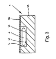
- the support 4 fills the cross-section of the channel 3 more than 30% in terms of area, in particular to more than 40% or 50%, as shown schematically in the cross-section according to FIG Fig. 3 indicated.
- the detection is facilitated Furthermore, thereby the fusion lengths can be reduced and / or required sample volumes are minimized.
- the carrier 4 is preferably formed dimensionally stable with a defined shape. This in turn is conducive to defined detection.
- the carrier 4 or at least its surface with the region 5 or the regions 5 is made of or coated with a non-luminous and / or non-fluorescent material. This facilitates the detection of substances connected in area 5.
- the carrier 4 or its surface with the at least one region 5 is at least substantially dark or particularly preferably black. This is conducive to optical detection.
- the carrier 4 is preferably formed very thin. In particular, its thickness (without guide means 10) is substantially between 10 ⁇ m and 500 ⁇ m.
- the length and / or extent in the movement device V of the carrier 4 is preferably between 1 mm and 10 mm.
- the width of the Carrier 4 is preferably between 0.5 mm and 5 mm.
- the length of the carrier 4 corresponds to its main extension.
- the width of the carrier 4 is at least a factor of 2, in particular by a factor of 3 or more greater than its thickness.
- the length of the carrier 4 preferably corresponds at least to the 1.5-flat, in particular at least 2-times or more, the width of the carrier 4.
- the longitudinal extent of the channel 3 is preferably at least twice the length of the carrier 4, in particular between 10 and 100 mm.
- the channel 3 preferably has at least substantially a rectangular cross-section or forms such.
- the clear height of the channel preferably corresponds at least to the thickness of the carrier 4 or, in particular at least 10%, more than this thickness, in particular between 10 .mu.m and 1 mm.
- the clear width of the channel 3 corresponds at least to the width of the carrier 4, in particular at least 10%, more. In particular, the clear width of the channel can be between 0.5 and 10 mm.
- the carrier 4 is preferably at least substantially in its main extension plane - in particular in the channel 3 and in the system - movable.
- the relatively thin design of the carrier 3 is beneficial to a low flow resistance.
- the carrier 4 is preferably at least substantially linearly movable in the channel 3 and / or in the channel 3 back and forth.
- the channel 3 is not rectilinear, but for example, winding or meandering or otherwise runs or is bent.
- the carrier 4 may then preferably be moved according to the channel 3 or in a portion or region of the channel 3.
- a single movable support 4 is provided in the device 1 or the channel 3 or the system. This is conducive to a defined movement and / or detection.
- the carrier 3 is preferably made of plastic or, a plastic part. This allows a favorable production or the use of material with desired properties.
- the carrier 4 is at least substantially made of PMA or PE.
- the carrier 3 is preferably an injection molded part or produced by injection molding. This allows a simple and inexpensive production and / or shaping.
- At least the upper side or flat side of the carrier 4 with the at least one detection or binding region 5 is at least essentially flat or smooth.
- the upper side or the detection or binding region 5 can also be microstructured or structured in any other way as required be.
- the structuring is, for example, in the schematic section according to Fig. 2 indicated in the areas 5.
- microstructuring can facilitate the binding of reagents such as antibody 7.
- the binding of the antibodies 7 or other reagents is particularly preferred is a plasma treatment of the carrier 4 or its top or flat side and / or the regions 5 and particularly preferably immobilization of the antibodies 7 on the carrier 4 or in the regions 5 he follows.
- the carrier 4 is preferably movable into different regions of the channel 3 or microfluidic system and / or into different liquids. This will be explained in more detail below.
- the carrier 4 is initially preferably movable within the sample 2 in the illustrated example, for example, reciprocating or alternating and / or vibratable thereto.
- the region a of the channel 3 or the system in which the sample 2 is located preferably forms a reaction chamber.
- the sample 2 is located only in this channel region a, so it is limited to a part of the channel 3.
- the channel 3 or the system preferably has a region b, which forms a gas space, that is not filled with the sample 2 or other liquids.
- the carrier 4 is preferably in the area from the area a b, that is, from position A to position B, movable and / or vice versa, preferably by means of the manipulation device 8.
- the carrier 4 is movable out of the liquid sample 2 or into it or over a phase boundary liquid-gas or gas-liquid 11 , in the Fig. 2 is indicated.
- the carrier 4 is movable out of the sample 2 or out of the reaction chamber into the gas space or vice versa.
- the detection is particularly preferably carried out in the gas space or outside a liquid. This is particularly beneficial for optical detection.
- a means 12 is preferably provided to retain liquid.
- the means 12 is a capillary stop or an abrupt cross-sectional widening, for example by a trench 13 formed in particular both in the bottom and in sidewalls of the channel 3.
- the means 12 may additionally also be provided by a surface area with different surface properties may be formed, for example, hydrophobic, if the retained sample 2 or other liquid is hydrophilic, or vice versa.
- the means 12 serves a "stripping" of the liquid or sample 2 from the carrier 4 when it is out of the liquid or sample 2 out - in particular directly into a gas space and / or a phase boundary 11 - moves.
- the means 12 can, in particular for this stripping, successively have a plurality of regions with reduced capillarity or different surface properties, for example a plurality of grooves, grooves 14 or the like, which are preferably smaller than the trench 13 in the illustrated embodiment.
- other constructive solutions are possible here.
- the means 12 is preferably arranged between the region a and b or in the region of the transition from the region a or sample 2 to the region b or the gas space.
- the trench 13 is arranged with the significantly reduced capillarity or the capillary directly directly adjacent to the reaction chamber or the area b or to the sample 2, wherein the further means for stripping liquid or grooves 14 or the like then preferably that of the liquid or sample 2 opposite Side - so the gas space - to the trench 13 or the like connect.
- the carrier 4 is preferably movable in different positions.
- the carrier 4 can be brought into contact with various liquids.
- a change of the liquid is carried out according to the proposal preferably a corresponding movement of the carrier 4 and a change in the position of the carrier 4.
- the liquid 15 is preferably received or held in a region c of the channel 3 or microfluidic system or the device 1.
- the region c preferably forms a further reaction chamber.
- the support 4 is preferably movable starting from the position a or from the sample 2, in particular over the region b or the gas space into the further liquid 15 or reaction chamber and / or the region c, as shown by position C in FIG Fig. 1 indicated.
- the carrier 4 is thus movable, for example, from the position A via the position B in the position C.
- the carrier 4 can in principle also be oppositely movable.
- a means 12 for retaining the liquid 15 is again preferably provided, as in FIG Fig. 1 indicated.
- the region b or the gas space is arranged between the region a or the reaction chamber formed therefrom and / or the sample 2 on the one hand and the region c or the reaction chamber formed therefrom and / or the liquid 15 on the other hand.
- the gas space or region b arranged therebetween can also be omitted or greatly shortened, for example, be formed only by a means 12 or only by a larger trench 13 or the like.
- the gas space or the means 12 between the areas a and c can be shortened in such a way be that the area b quasi deleted and / or shorter than the length of the carrier 4 is.
- the means 12 or the grooves 14 or the like extend over a distance in the direction of movement of the carrier 4 or longitudinal extent of the channel 3, which corresponds substantially to the length of the carrier 4 or in particular is significantly longer.
- the means 12 between the sample 2 and liquid 15 or between two other liquids can be dispensed with altogether, in particular if the liquids are immiscible and form a phase boundary, for example by appropriate stratification, by which the carrier 4 is movable
- the device 1 or the channel 3 or the system preferably or optionally on the liquid other than the sample 15, a further liquid 16, in which the carrier 4 (as needed) is movable.
- the device 1 or the channel 3 or the system preferably has a further regions for receiving or for holding the liquid 16.
- the carrier 4 is in the illustrated example, starting from the position C or from the region c over a region d, which forms an optional further gas space, or via the position D in the region e or the position E, ie in the further liquid 16 movable.
- each region c and d on the one hand, and the regions d and e, on the other hand, preferably in each case means 12 or trenches 13 and / or grooves 14 or the like are arranged.
- the means 12 of the device 1 or of the channel 3 can in principle be designed to be at least substantially the same or as required, for example due to the use of different liquids or the like, also differently.
- the carrier A is preferably movable starting from the position A via the position B, C and D in the position E.
- the residence time of the carrier 4 in the individual position or areas and / or in the individual liquids or in the sample 2 can be varied as desired.
- the detection is particularly preferably carried out in a gas space.
- a detection in the area b or d or in the position B or D done. Possibly. can also be carried out in both areas or positions in each case a detection, ie in Hereen different areas or positions a successful detection gene. If necessary, different detections can be made in the different areas or position.
- multistage or different reactions can be carried out, detected or monitored in succession.
- the carrier 4 is preferably moved into different reaction chambers. It can also be changed in a reaction chamber or in an area the respective liquid if necessary. For example, instead of the first liquid-forming sample 2 before or after another liquid can be filled in the area a. For or when changing the liquid, the carrier 4 can then either either remain in the region a or be moved to another region, in particular into the gas space or adjacent region b.
- the individual areas may have a different length.
- individual or all filled with liquid areas here the areas a, c and e, each adapted to the size or length of the carrier 4 such that the carrier 4 - if desired - in sufficient extent within the respective area or within the liquid is movable, but on the other hand, the required liquid volume is low or even minimized.
- This can be done by adjusting the length of the respective area.
- the length is particularly preferred the respective area and / or the longitudinal extent of the means 12 preferably at least substantially each between 1.2 times and 10 times, more preferably between 1.5 times and 3 times the length of the carrier 4 or extension of the Carrier 4 in the direction of movement.
- the carrier 4 Due to the volume displacement by the carrier 4, it may be possible or expedient to dimension the required liquid volume so that in particular the preferred longitudinal extent or an at least substantially complete filling the respective areas (especially first) in the state of the present in the liquid carrier. 4 be achieved. This too can lead to a minimization of the liquid volume required in each case.
- a minimization of the required liquid volumes can be achieved in that the carrier 4 fills the channel 3 in cross section in area to at least 30%, preferably more than 40%, in particular more than 50%.
- the carrier 4 is formed in cross section at least substantially konkludent to the cross section of the channel 3 or vice versa.
- the carrier 4 is preferably movable in the longitudinal extension of the channel 3 and along the channel 3, as by case V in Fig. 2 indicated schematically.
- the support 4 can also be movable transversely thereto, in particular in its surface extension and / or parallel to the surface extension of the device 1 or the base part 1b or cover 1a, preferably by means of the manipulation device 8 and / or by other actions.
- the manipulating device 8 preferably has a plurality of correspondingly positioned electromagnets, wherein the electromagnets in particular in required Are controllable in order to achieve the desired magnetic field M or the desired gradient.
- the position of the carrier 4 in the device 1 or in the channel 3 or microfluidic system can be detected.
- This is done in particular inductively.
- this can be done inductively by means of a corresponding coil or a plurality of coils and / or by means of the electromagnets or the coils of the electromagnets of the manipulation device 8.
- the detection of the position of the carrier 4 additionally or alternatively in other ways, for example, optically done.
- the channel 3 preferably has an at least substantially constant cross-section and / or an at least substantially smooth or flat bottom or other guide surface for the carrier 4.
- the means 12, trenches 13 and / or grooves 14 or the like are preferably relatively short interruptions and / or cross-sectional widenings in the direction of movement V of the carrier 4, ie they have a particularly short extent in this direction, in particular a good guidance of the carrier 4 and / or to allow easy movement or sliding of the carrier 4 or to make sure.
- guide means may be formed, which are for example web-like, rail-like or runner-like and / or project to reduce the sliding resistance of the carrier 4 and / or to guide the carrier 4, for example, longitudinally displaceable.
- the device 1 preferably has at least one detection device 17, which in particular comprises one or more measuring or sensor devices 18, as in FIG Fig. 2 indicated.
- the detection device 17 may also be associated with the device 1, in particular forming part of a test device, as will be explained later.
- the detection device 17 is in particular for the detection of an analyte or substance, such as a complex 6 of the analyte, optionally also of various substances or complexes 6 of different analytes, which are present at a region 5 or in different substances or regions 5 of the carrier 4, in particular bound, formed,
- the detection device 17 preferably operates optically, in particular by a luminescence or fluorescence measurement. This is possible for example because the substances or complexes 6 or the analytes to be detected contain corresponding optical properties or markers. For example, by means of the detection device 17 or by means of corresponding measuring or sensor devices 18, it is also possible to determine a plurality of different or different substances or analytes, in particular in or on different regions 5, as in FIG Fig. 2 only indicated schematically.
- the detection is therefore preferably optical, in particular by fluorescence or luminescence. However, additionally or alternatively, any other detection can take place.
- the measured values of the detection device 17 can be evaluated and / or further processed in the detection device 17 and / or separately therefrom - in a separate evaluation unit, not shown - and in particular also displayed or output in any other way.
- a separate evaluation unit not shown - and in particular also displayed or output in any other way.
- the content of a particular analyte or the contents of various analytes in the sample 2 can be stored, displayed and / or output.
- the proposed device 1 is particularly suitable or intended for the adaptation and implementation of miniaturized immunoassays.
- the proposed device 1 is in particular a cartridge concept.
- the proposed device 1 is in particular provided or suitable for measuring parameters or analytes in blood plasma, blood serum or the like as sample 2.
- the device 1 preferably has a receptacle 19a for the sample 2 or blood or other body fluid or the like.
- the receptacle 19a is formed for example as a receiving opening in the lid 1b, but can also be realized in other ways.
- the receptacle 19a is connected, for example, via a connecting channel 2 to the channel 3 or its region a or the reaction chamber formed therefrom, in order to guide the sample 2 or the like in particular automatically by capillary forces into the reaction chamber or into the region a and with it to fill the sample 2.
- the receptacle 19a or device 1 may additionally contain a device for separating blood, such as a filter, a membrane or the like, in particular the blood plasma or blood supplied for example in the receptacle 19a or blood supplied in another way Separate blood serum and pass as sample 2 in the area a or the reaction chamber formed thereof.
- a device for separating blood such as a filter, a membrane or the like, in particular the blood plasma or blood supplied for example in the receptacle 19a or blood supplied in another way Separate blood serum and pass as sample 2 in the area a or the reaction chamber formed thereof.
- the device 1 makes it possible to minimize the * sample and reagent requirements.
- the proposed device 1 allows a simple structure, a simple design, a simple assembly and / or a simple handling.
- the device 1 allows a miniaturized detection, in particular fluorometric detection.
- the proposed device 1 allows the simultaneous detection or determination of several parameters or analytes.
- the proposed device 1 forms a closed system, in particular self-contained.
- other than the sample 2 or the blood or other liquids should or should be added no further reagents, substances or the like.
- the device 1 particularly preferably allows the performance of classical, modified and / or miniaturized immunoassays, more preferably in the form of sandwich assays or competitive immunoassays.
- a basic idea of the proposed device 1 method is to move a fat body, namely the carrier 4, through a cavity, in particular in the form of the channel 3, another chamber or in another, in particular microfluidic system.
- the movement is effected in particular by a magnetic field gradient, as already explained.
- the sample 2 e.g. pressure-driven and / or by capillary forces, transported or conducted in the reaction chamber or in the channel 3 or the region a.
- the reaction chamber or the region a is preferably filled with a defined volume of the sample 2.
- reaction chamber or the region a can simultaneously serve as a chamber for the reaction and detection.
- the sample 2 is preferably brought into contact with a reagent 21, which is particularly preferably held in a dry form or is already in the channel 3 or area a or the reaction chamber.
- a reagent 21 is particularly preferably held in a dry form or is already in the channel 3 or area a or the reaction chamber.
- the reagent is disposed in the lid 1B and applied thereto and dried.
- the reagent 21 is dissolved by the sample 2 and can react with the sample 2 or an analyte of the sample 2. If required, the dissolution of the reagent 21 can be assisted by a corresponding movement of the carrier 4 in the region a or in the reaction chamber.
- the carrier 4 may already be located in the reaction chamber or the region a when the sample 2 is introduced or may only be moved into it after the sample 2 has been introduced therein.
- the reagent 21 preferably contains a conjugate for an analyte of the sample 2 to be determined. If required, the reagent 21 can at least essentially only be determined from the conjugate and / or contain other substances and substances. Preferably, the reagent 21 or the conjugate has at least partially an especially fluorescent and / or luminescent and / or other marker property.
- the reagent 21 or conjugate which is initially stored in dry form, is reconstructed with the sample 2. It may then react with the analyte in sample 2 and in particular form an analyte-conjugate complex 6.
- analyzable surface 4A or, in the preferably visible detection or binding region 5 or in the preferably visible detection or binding regions 5 in the illustrated embodiment are particularly preferred catcher 7 or other complex with the 6th reacting substances preferably immobilized.
- the mobility or mobility of the carrier 4, the geometric freedom in the design and arrangement of the regions 5 and / or by the controlled movement, in particular by means of a magnetic field M or magnetic field gradients result in many handling and functional possibilities.
- the sample 2 and the conjugate for example, can be ideally homogenized and reacted. Furthermore, an optimal complex formation or other reaction can take place.
- the carrier 4 can simultaneously assume the function of a mixer.
- a sandwich complex can be formed.
- the analyte-conjugate complex 6 reacts with the immobilized antibodies 7 on the support 4 and forms a sandwich complex (Capture antibody - analyte, detector antibody).
- This condition is schematic in Fig. 2 in which case the carrier 4 has already been moved out of the sample 2 or out of the region A into another region, in particular into the region b or a gas space.
- the conjugates may also be designated as detector antibodies or contain or be formed therefrom, in particular since they are intended to react or bind specifically with the analyte of sample 2.
- the reagent 21 or conjugate preferably contain an optical marker or an optically active substance which, if appropriate, may also be formed by the detector antibody itself.
- the washing liquid is introduced into the reaction chamber or the region a and thereby the sample 2 displaced or removed, for example via an overflow channel, not shown, in a Kochlaulhunt, not shown, or the like.
- the carrier or its surface 4A or the region 5 is washed simultaneously.
- the introduction of the washing liquid can be effected for example by compressed air and / or capillary force and / or in any other way.
- the sample 2 can also be removed or removed beforehand, ie before the washing liquid is introduced.
- the washing liquid is held or received in a separate reaction chamber or in a separate region c of the device 1.
- the liquid 15 and / or 16 forms such a washing liquid or another, different from the sample 2 or different liquid.
- the carrier 4 is then washed by moving into the liquid 15 and / or 16 or in the corresponding areas c and / or e, or subjected to other reactions or treatments.
- the filling of the liquids 15 and 16 is preferably carried out via corresponding receptacles 19c and 19e and connecting channels 20c and 20e.
- the filling can be done in particular in a similar manner as the filling of the device 1 with the sample 2, so that the relevant statements apply accordingly.
- the receptacles 20c and 20e are preferably again formed by filling openings in the lid 1b.
- the transfer of the liquids 15 or 16 into the corresponding regions c or e or thereof formed reaction chambers again takes place preferably by capillary forces, optionally by compressed air and / or in any other suitable manner.
- the liquids 15 and 16 can basically be different liquids. However, it may also be the same liquid, for example a washing liquid. In this case, the two areas c and e or the reaction chambers formed therefrom may, if necessary, also be fillable with the liquid via a common receptacle.
- the detection takes place.
- the detection is carried out in particular optically, particularly preferably from the side to which the surface 4A or the region 5 has, on which is detected.
- these are particularly preferably arranged on a common flat side, surface 4A or upper side of the carrier 4.
- a fundamentally different arrangement is possible.
- the carrier 4 separate or different areas 5 may be formed.
- a detection can also take place from different sides and / or in different places.
- the various regions 5 may be used simultaneously or sequentially for reactions or for binding analytes or the like and / or for detection.
- a detection is basically possible either through the base part 1A or through the lid 1B.
- the detection preferably takes place through the lid 1B.
- the cover 1B is sufficiently transparent at least in the required detection area.
- the carrier 4, with its region 5 or its regions 5, preferably points towards the lid 1B accordingly.
- the carrier 4 or its detection or binding region 5 or several or all detection or binding regions 5 can be pressed against the preferably transparent wall.
- a pressing against the lid 1A or vice versa is possible.
- the cover 1A can be designed here to be, for example, elastically deformable, in particular a film-like manner. This allows in particular to reduce or minimize the influence of liquid on the optical detection when the carrier 4 is still in the liquid for detection or is still covered with (residues of) liquid. Also, disturbances due to transitions from and / or to the gas phase can be avoided. At the same time, this results in a particularly precise positioning and / or focusing of the surface for the optical measurement, in particular the preferred luminescence or fluorescence measurement.
- the detection or the optical measurement takes place in a gas space, ie when the carrier 4 has previously been moved out of the respective liquid, such as the sample 2, liquid 14 or 16.
- the respective liquid such as the sample 2, liquid 14 or 16.
- the detection is preferably carried out optically or by measuring or determining the luminescence, preferably the photoluminescence, in particular the fluorescence.
- the detection device 17 or its measuring or sensor device 18 is designed accordingly and includes, for example, a CCD sensor or other photosensor or the like.
- the detection device 11 preferably also includes a corresponding light source or the like.
- the detection which preferably takes place in a gas space, can take place, for example, in the region b and / or d.
- a detection in liquid so in particular in the range a, c and / or e take place.
- the carrier 4 may be provided with corresponding markings, optically detectable regions, in particular fluorescent regions or the like.
- the detection or measured values can be evaluated in the detection device 11 itself and / or in a downstream evaluation and output in particular in the form of a content of the analyte to be detected in the sample 2. With different analytes to be detected, different contents or other different parameters can be output accordingly.
- the pressing of the carrier 4 on the transparent wall or the cover 1B can also be done by the manipulation device 8 or magnetically.
- the proposed device 1 is universally applicable and allows in particular the controlled flow of multi-stage reactions and / or the detection of various substances or analytes and / or a determination of various parameters.
- the device 1 may also form part of a larger microfluidic system or drain.
- the device 1, the channel 3 or the particular microfluidic system may have a plurality of, in particular two or more, carriers 4 which are optionally simultaneously or successively inserted into the sample 2 or the reaction chamber or region 2 and / or into a gas space or other reaction chamber or liquid 15 or 16 are movable.
- the carriers 4 are then used in particular for the detection or determination of different analytes and / or parameters or the like.
- the device 1 or the channel 3 is preferably provided with a suitable vent.
- at least one ventilation duct 1 C is provided, which is connected in particular to a gas space.
- a separate venting channel 1C is connected to a gas space, here to the areas b and d.
- only a single ventilation channel 1C can be sufficient.
- the venting channel 1C may each be optionally formed in the base part 1A and / or cover 1B or end.
- the base part 1A or the bottom of the channel 3 can have favorable properties, such as a certain color or other surface properties.
- the carrier 4 may also have recesses or other means to transport, for example, the sample 2, in particular a certain volume of the sample 2, and / or record.
- the support 4 may itself be in the form of a microfluidic system with at least one channel, a chamber and / or a reservoir for a reagent or the like.
- the carrier 4 can also serve to transport at least one reagent, for example the reagent 21.
- the carrier 4 may be provided with the dried-in reagent 21, which dissolves in the desired manner when the carrier 4 is introduced into the sample 2 or another liquid and then can react, for example.
- the carrier 4 is provided or equipped with all reagents 21, antibodies 7 and / or other substances or substances which are required for the determination or detection of a particular analyte or several specific analytes or parameters or the like.
- a suitable carrier 4 can be inserted into the device 1 or the channel 3.
- different carriers 4 in a channel 3 and a microfluidic system for Determination of different analytes, parameters or the same can be used.
- the various carriers 4 can then be successively moved into the sample 2 or brought into contact therewith.
- the detection or binding regions 5 on the carrier 4 may also be omitted, in particular if the carrier 4 is used, for example, only or substantially only for mixing or transport purposes and / or forms another reaction system or microfluidic system or the like.
- detection or binding regions 5 are particularly preferably microstructured, as already mentioned. However, such microstructuring is only optional.
- Immobilizing the antibodies 7 on the carrier 4 or its surface 4a or in the respective detection or binding region 5 or in different detection or binding regions 5 by prior plasma coating and / or silanization of the carrier 4, at least into the desired one, is particularly preferred areas.
- a so-called photolinking of the antibody 7 can take place, whereby the density of the bound antibodies 7 can be substantially increased.
- any suitable treatment is possible. This is a further advantage of the proposed device 1, the proposed carrier 4 and the proposed method.
- Fig. 4 shows in a schematic, too Fig. 1 Corresponding plan view of a second embodiment of the proposed device 1.
- the channel 3 here has a branch or forms a kind of switch.
- the carrier 4 is starting from the region b or from preferably only a single gas space optionally in a plurality, in particular in at least three different areas a, c and d and / or reaction chambers movable, in particular optionally in at least three different liquids, namely the sample 2, the liquid 15 and the liquid sixteenth
- the movement of the carrier 4 is preferably controlled again by the manipulation device 8, not shown here.
- the device 1 or the channel 3 or the preferably microfluidic system may also have a plurality of branches or a branch with even more different channel regions or channel buttons or the like.
- a plurality of carriers 4 in the device 1 or the channel 3 or the system can be used, which can be arranged in the desired manner depending on the number of branches, reaction chambers or the like, in particular desired processes, manipulations and / or investigations perform.
- Fig. 5 shows a schematic section of a proposed test device 22 with the proposed device 1.
- the test device 22 has in particular a receiving area 23 for the device 1.
- the receiving region 23 is designed in particular as an insertion region and / or slit-like.
- the device 1 it is also possible, for example, for the device 1 to be placed on the receiving area 23 of the test device 22 for detection or evaluation, or in any other way with the test device 22 or the receiving area 23 in preferably mechanical contact or at least in the vicinity is brought about, in particular to allow the magnetic manipulation of the carrier 4 and / or the preferably optical detection.
- the test device 22 preferably has the detection device 17 with the measuring or sensor devices 18 for the already explained detection, in particular optical detection, particularly preferably by luminescence and / or fluorescence measurement.
- the test device 22 preferably has the manipulation device 8 or the electromagnets, which are preferably provided for this purpose, and particularly preferably an associated controller, not shown, or the like.
- the manipulation device 8 By means of the manipulation device 8, the carrier 4 is moved in the desired manner as already explained, in the device or in the channel 3 or microfluidic system.
- the measured values of the detection device 17 are preferably detected, recorded, further evaluated, stored and / or further processed by an evaluation device 24 and output, for example, via an output device 25 of the test device 22.
- the output device 25 can in particular be a display, but also an interface or the like.
- test device 22 represents a preferably mobile device that can be used together with the device 1 as a POC system.
- the proposed POC system of test device 22 and device 1 can accordingly be used universally.
- the device 1 can first be filled with the sample 2 and then introduced into the receiving region 23 of the test device 22 in order to carry out the desired reaction, detection and evaluation.
- the carrier 4 in the device 1 is preferably held securely in a predetermined area, for example the area a or the area b, until the actual use of the device 1 takes place, in particular until the sample 2 is filled.
- the device 1 and / or the carrier 4 may be provided with a corresponding holding means.
- the holding means may be, for example, a sticking, sticking or the like.
- the holding means may also be formed by a mechanical or chemical compound or the like.
- the holding means may also be realized by a positive or positive connection, for example a pinching or the like.
- the carrier 4 may also be magnetically held at a desired position, for example by installation a permanent magnet in the device 1 and the base part 1A at a desired location.
Abstract
Description
Die vorliegende Erfindung betrifft eine Vorrichtung zur Manipulation und/oder Untersuchung einer flüssigen Probe gemäß dem Oberbegriff des Anspruchs 1.The present invention relates to a device for manipulating and / or examining a liquid sample according to the preamble of
Die vorliegende Erfindung befasst sich insbesondere mit der Diagnostik bei mikrofluidischen Proben, besonders bevorzugt bei so genannten Point-Off-Care-Systemen (POC-Systemen). Insbesondere befasst sich die vorliegende Erfindung mit vorzugsweise miniaturisierten Immunoassays, also der Untersuchung von Proben unter Einsatz von Antikörpern. Besonders bevorzugt betrifft die vorliegende Erfindung so genannte Cartridge-Konzepte, also kleine, insbesondere kartenartige Vorrichtungen, zur Manipulation und/oder Untersuchung einer flüssigen Probe bzw. Realisierung von Immunoassays.The present invention is concerned in particular with the diagnostics of microfluidic samples, particularly preferably so-called point-off-care systems (POC systems). In particular, the present invention is concerned with preferably miniaturized immunoassays, that is the study of samples using antibodies. The present invention particularly preferably relates to so-called cartridge concepts, ie small, in particular card-type, devices for the manipulation and / or examination of a liquid sample or realization of immunoassays.
Die
Die
Die
Die
Die
Die
Die
Sawetzki (
In der
Karle et al. (
Es hat sich gezeigt, dass die Vielzahl von kleinen magnetischen, im Wesentlichen kugelförmigen oder eine sonstige undefinierte Form aufweisenden Partikeln keine optimale Manipulation oder Untersuchung einer flüssigen Probe gestattet. Insbesondere ist keine optimale optische Detektion des Bindens von Analyten oder Komplexen an den Trägerpartikeln möglich.It has been found that the plurality of small magnetic, substantially spherical or other undefined shape particles does not allow optimal manipulation or examination of a liquid sample. In particular, no optimal optical detection of the binding of analytes or complexes to the carrier particles is possible.
Der vorliegenden Erfindung liegt die Aufgabe zugrunde, eine Vorrichtung und ein Verfahren zur Manipulation und/oder Untersuchung einer flüssigen Probe insbesondere in einem mikrofluidischen System bzw. Kanal anzugeben, wobei eine optimierte Manipulation oder Untersuchung und/oder eine verbesserte, vorzugsweise optische Detektion - insbesondere zum Nachweis einer Reaktion oder zur Bestimmung eines Analyten - ermöglicht wird bzw. werden und/oder wobei mehrere Untersuchungen parallel an einer Probe unter definierten Bedingungen und/oder räumlich getrennt durchgeführt werden können.The object of the present invention is to provide a device and a method for manipulating and / or examining a liquid sample, in particular in a microfluidic system or channel, wherein optimized manipulation or examination and / or improved, preferably optical detection - in particular for Proof of a reaction or for the determination of an analyte - is or will be made possible and / or wherein several examinations can be performed in parallel on a sample under defined conditions and / or spatially separated.
Die obige Aufgabe wird durch eine Vorrichtung gemäß Anspruch 1 gelöst. Vorteilhafte Weiterbildungen sind Gegenstand der Unteransprüche.The above object is achieved by a device according to
Die vorliegende Erfindung befasst sich mit der Manipulation und/oder Untersuchung einer flüssigen Probe insbesondere in einem mikrofluidischen Kanal oder System. Unter "mikrofluidisch" sind erfindungsgemäß Volumina von vorzugsweise weniger als 10 ml, besonders bevorzugt von weniger als 1 ml, und/oder Kanal- oder Flilssigkeitsquerschnitte (maximaler Durchmesser) von vorzugsweise weniger als 2 mm, besonders bevorzugt von weniger als 500 µm, zu verstehen.The present invention is concerned with the manipulation and / or examination of a liquid sample, in particular in a microfluidic channel or system. According to the invention, "microfluidic" is to be understood as meaning volumes of preferably less than 10 ml, more preferably less than 1 ml, and / or channel or liquid cross-sections (maximum diameter) of preferably less than 2 mm, particularly preferably less than 500 μm ,
Bei der vorliegenden Erfindung wird ein in einem vorzugsweise mikrofluidischen Kanal bzw. System beweglicher Träger eingesetzt, der mindestens einen Detektions- oder Bindungsbereich für einen Stoff aufweist. Dieser kann ein Analyt der Probe oder ein davon gebildeter Komplex oder davon abhängiges Reaktionsprodukt und/oder ein Reagenz sein, das mit der Probe, einem Analyten der Probe, einem Komplex davon oder dergleichen wechselwirkt oder bindet. Beispielsweise kann das Reagenz mit einem Komplex des Analyten oder mit einem vom Analyten abhängigen Reaktionsprodukt wechselwirken oder binden. Vorzugsweise ist das Reagenz selbst in oder auf dem Detektions- bzw. Bindungsbereich fixiert oder immobilisiert. Insbesondere kann der Detektions- bzw. Bindungsbereich einen immobilisierten Antikörper enthalten oder aufweisen, der mit einem Analyten der Probe oder einem den Analyten enthaltenden Komplex wechselwirkt, besonders bevorzugt bindet. In diesem Fall wird das Reagenz durch den Antikörper gebildet, der mit dem Analyten indirekt, nämlich mit einem den Analyten enthaltenden Komplex oder dergleichen, wechselwirkt. Es sind aber auch andere Wechselwirkungen oder Reaktionen realisierbar, beispielsweise eine Modifikation des Reagenzes oder Detektions- bzw. Bindungsbereichs oder ein Lösen des Reagenzes. Der Begriff "Wechselwirken" ist dementsprechend vorzugsweise in einem weiten Sinne bei der vorliegenden Erfindung zu verstehen.In the present invention, a carrier which is movable in a preferably microfluidic channel or system and has at least one detection or binding region for a substance is used. This may be an analyte of the sample or a complex formed therefrom or its dependent reaction product and / or a reagent that interacts or binds with the sample, an analyte of the sample, a complex thereof or the like. For example, the reagent may interact or bind with a complex of the analyte or with an analyte-dependent reaction product. Preferably, the reagent itself is fixed or immobilized in or on the detection or binding region. In particular, the detection or binding region may contain or have an immobilized antibody which interacts with an analyte of the sample or a complex containing the analyte, particularly preferably binds. In this case, the reagent is formed by the antibody, which interacts indirectly with the analyte, namely with a complex containing the analyte or the like. But there are also other interactions or reactions feasible, for example, a modification of the reagent or detection or binding region or a release of the reagent. Accordingly, the term "interacting" is preferably to be understood in a broad sense in the present invention.
Gemäß einem Aspekt der vorliegenden Erfindung ist der Träger zumindest im Wesentlichen eben oder plattenförmig ausgebildet und/oder insbesondere mit einer zumindest im Wesentlichen flachen oder ebenen Oberseite mit dem Detektions- bzw. Bindungsbereich versehen. Dies ist einer guten bzw. definierten Detektion bzw. Bestimmung eines Analyten zuträglich.According to one aspect of the present invention, the carrier is at least substantially flat or plate-shaped and / or in particular provided with an at least substantially flat or flat upper side with the detection or binding region. This is conducive to good or defined detection or determination of an analyte.
Gemäß einem weiteren Aspekt der vorliegenden Erfindung ist der Träger in einer definierten Ausrichtung in dem oder von dem Kanal geführt. Insbesondere ist der Träger in dem Kanal nicht umdrehbar, sondern weist vorzugsweise mit einer Flachseite und/oder seiner den Detektions- bzw. Bindungsbereich enthaltenden Seite zu einer Seite (insbesondere Flachseite) der Vorrichtung bzw. des Kanals. Dies gestattet eine besonders gute, insbesondere optische Detektion von der letztgenannten Seite her und vereinfacht damit den Aufbau der Vorrichtung bzw. die Detektion generell.According to another aspect of the present invention, the carrier is guided in a defined orientation in or from the channel. In particular, the carrier is not reversible in the channel, but preferably has a flat side and / or its side containing the detection or binding area to a side (in particular flat side) of the device or of the channel. This allows a particularly good, in particular optical detection of the latter side and thus simplifies the structure of the device or the detection in general.
Gemäß einem anderen Aspekt weist der Träger eine Länge auf, die größer als der maximale Querschnitt des Kanals ist. Dies gestattet eine wesentlich definiertere Bewegung und/oder Ausrichtung des Trägers in dem Kanal bzw. mikrofluidischen System als beim Stand der Technik. So kann ein wesentlich definierterer Verfahrensablauf und/oder eine bessere bzw. definiertere, insbesondere optische Detektion erfolgen.In another aspect, the carrier has a length that is greater than the maximum cross-section of the channel. This allows a much more defined movement and / or orientation of the carrier in the channel or microfluidic system than in the prior art. Thus, a much more defined process flow and / or a better or more defined, in particular optical detection can take place.
Gemäß einem weiteren Aspekt füllt der Träger den Querschnitt des Kanals zu mehr als 30 %, vorzugsweise mehr als 40 %, insbesondere mehr als 50 % flächenmäßig aus. Hierdurch können die erforderlichen Volumina minimiert und/oder die auftretenden Diffusionslängen bzw. Reaktionszeiten reduziert werden.According to a further aspect, the carrier fills the cross-section of the channel to more than 30%, preferably more than 40%, in particular more than 50% in terms of area. As a result, the required volumes can be minimized and / or the diffusion lengths or reaction times occurring can be reduced.
Gemäß einem weiteren Aspekt ist der Träger formstabil mit einer definierten Form ausgebildet. Dies ist wiederum einer definierten Detektion zuträglich.According to a further aspect, the carrier is formed dimensionally stable with a defined shape. This in turn is conducive to defined detection.
Gemäß einem weiteren Aspekt ist nur ein einziger Träger zur Detektion und/oder in dem Kanal vorgesehen. Dies ist einer definierten Detektion zuträglich.In another aspect, only a single carrier is provided for detection and / or in the channel. This is conducive to defined detection.
Gemäß einem weiteren Aspekt ist der Träger, insbesondere mittels einer Manipuliereinrichtung, aus der Probe heraus, insbesondere in einem Gasraum, bzw. über oder durch eine Phasengrenze bewegbar. Dies ist wiederum einer insbesondere optischen Detektion zuträglich.According to a further aspect, the carrier, in particular by means of a manipulation device, is movable out of the sample, in particular in a gas space, or over or through a phase boundary. This in turn is conducive to a particular optical detection.
Unter dem Begriff "Detektion" ist bei der vorliegenden Erfindung vorzugsweise das Erfassen einer Wechselwirkung, Modifikation oder Reaktion im Detektions- bzw. Bindungsbereich und/oder das Binden eines Stoffs, wie eines Analyten, Komplexes oder dergleichen, im Detektions- bzw. Bindungsbereich zu verstehen, um eine vorzugsweise qualitative und/oder quantitative Untersuchung der Probe, insbesondere eine qualitative und/oder quantitative Bestimmung mindestens eines Analyten der Probe, zu ermöglichen. Die Detektion kann insbesondere optisch, besonders bevorzugt durch Lumineszenz- oder Fluoreszenzmessung, erfolgen.The term "detection" in the present invention is preferably understood to mean the detection of an interaction, modification or reaction in the detection or binding region and / or the binding of a substance, such as an analyte, complex or the like, in the detection or binding region in order to allow a preferably qualitative and / or quantitative examination of the sample, in particular a qualitative and / or quantitative determination of at least one analyte of the sample. The detection can be carried out in particular optically, particularly preferably by luminescence or fluorescence measurement.
Gemäß einem weiteren Aspekt ist der Träger als ein Kunststoffteil und/oder Spritzgussteil ausgebildet. Dies gestattet eine einfache, kostengünstige Herstellung und/oder die Realisierung definierter Eigenschaften und/oder eine Erleichterung der Massenproduktion.According to a further aspect, the carrier is designed as a plastic part and / or injection molded part. This allows a simple, cost-effective production and / or the realization of defined properties and / or a facilitation of mass production.
Gemäß einem weiteren Aspekt ist der Detektions- bzw. Bindungsbereich zumindest teilweise mikrostrukturiert. Unter "Mikrostrukturierung" ist vorzugsweise eine sich insbesondere wiederholende Struktur und/oder eine Struktur mit einer mittleren Strukturbreite von 10 nm bis 500 µm, vorzugsweise weniger als 10 µm, und/oder mit Erhebungen oder Vertiefungen von 10 nm bis 500 µm, vorzugsweise weniger als 10 µm, zu verstehen. Die Mikrostrukturierung dient einer Oberflächenvergrößerung und/oder erleichtert das Binden eines Stoffes, wie eines Analyten oder Reagenzes, insbesondere eines Antikörpers oder dergleichen, im Detektions- bzw. Bindungsbereich.According to another aspect, the detection or binding region is at least partially microstructured. By "microstructuring" is preferably a particularly repeating structure and / or a structure having an average structure width of 10 nm to 500 .mu.m, preferably less than 10 .mu.m, and / or with elevations or depressions of 10 nm to 500 .mu.m, preferably less than 10 μm, to understand. The microstructuring serves to increase the surface area and / or facilitates the binding of a substance, such as an analyte or reagent, in particular an antibody or the like, in the detection or binding region.
Gemäß einem weiteren Aspekt kann der Träger in verschiedene Flüssigkeiten, beispielsweise von der flüssigen Probe in eine andere Flüssigkeit oder umgekehrt, und/oder wahlweise in verschiedene Reaktionskammern bewegbar sein. Dies ist wiederum einer optimierten Reaktionsführung, einem optimierten Ablauf verschiedener Schritte und/oder einer optimierten Detektion zuträglich.In a further aspect, the carrier may be movable into different liquids, for example from the liquid sample to another liquid or vice versa, and / or optionally into different reaction chambers. This in turn is conducive to an optimized reaction procedure, an optimized sequence of different steps and / or an optimized detection.
Gemäß einem weiteren Aspekt wird der Träger aus der Probe heraus in einen Gasraum des Systems zur Detektion eines im Detektion- oder Bindungsbereich gebundenen Stoffs bewegt. Dies gestattet eine optimierte, insbesondere optische Detektion, besonders bevorzugt mittels Lumineszenz- oder Fluoreszenzmessung.According to a further aspect, the carrier is moved out of the sample into a gas space of the system for detecting a substance bound in the detection or binding region. This allows an optimized, in particular optical detection, particularly preferably by means of luminescence or fluorescence measurement.
Alternativ oder zusätzlich kann der Träger 4 durch den Gasraum, in eine von der Probe verschiedene Flüssigkeit oder umgekehrt bewegt werden. So können verschiedene Schritte, wie Inkubationsschritte, Wasch-Schritte oder dergleichen, insbesondere mit minimalen Flüssigkeitsvolumina realisiert werden.Alternatively or additionally, the
Die genannten Aspekte der vorliegenden Erfindung sowie die sich aus der nachfolgenden Beschreibung und den Ansprüchen ergebenden sonstigen Aspekte und Merkmale der vorliegenden Erfindung können unabhängig voneinander, aber auch in beliebiger Kombination realisiert werden.The mentioned aspects of the present invention as well as the other aspects and features of the present invention resulting from the following description and the claims can be realized independently of one another, but also in any desired combination.
Weitere Aspekte, Merkmale, Eigenschaften und Vorteile der vorliegenden Erfindung ergeben sich aus den Ansprüchen und der nachfolgenden Beschreibung bevorzugter Ausführungsformen anhand der Zeichnung. Es zeigt:
- Fig. 1
- eine schematische Draufsicht einer ersten Ausführungsform einer vorschlagsgemäßen Vorrichtung;
- Fig. 2
- einen schematischen Längsschnitt der Vorrichtung;
- Fig. 3
- einen schematischen Querschnitt der Vorrichtung;
- Fig. 4
- eine schematische Draufsicht einer zweiten Ausfuhrungsform der vorschlagsgemäßen Vorrichtung; und
- Fig. 5
- eine schematische Schnittdarstellung einer Testeinrichtung mit der vorschlagsgemäßen Vorrichtung.
- Fig. 1
- a schematic plan view of a first embodiment of a proposed device;
- Fig. 2
- a schematic longitudinal section of the device;
- Fig. 3
- a schematic cross section of the device;
- Fig. 4
- a schematic plan view of a second embodiment of the proposed device; and
- Fig. 5
- a schematic sectional view of a test device with the proposed device.
In den Figuren werden für gleiche oder ähnliche Bauteile und Komponenten die gleichen Bezugszeichen verwendet, wobei sich entsprechende oder ähnliche Vorteile und Eigenschaften ergeben, auch wenn eine wiederholte Beschreibung weggelassen ist.In the figures, the same reference numerals are used for the same or similar components and components, with corresponding or similar advantages and properties, even if a repeated description is omitted.
Die Vorrichtung 1 weist vorzugsweise (mindestens) einen insbesondere mikrofluidischen Kanal 3 zur Aufnahme der Probe 2 auf. Der Kanal 3 oder die Vorrichtung 1 bildet insbesondere ein mikrofluidisches System oder einen Teil davon.The
Wie in einem schematischen Längsschnitt der Vorrichtung 1 gemäß
Das Basisteil 1A ist vorzugsweise als Kunststoffteil und/oder Spritzgussteil ausgebildet. Das Basisteil 1A ist vorzugsweise zumindest im Wesentlichen flach, eben, plattenartig und/oder steif ausgebildet. Der Kanal 3 bzw. das mikrofluidische System ist vorzugsweise in oder entlang einer Flachseite des Basisteils 1A gebildet und/oder zu einer Flachseite hin offen. Der Kanal 3 bzw. die Vertiefung bzw. Flachseite ist durch den Deckel 1B vorzugsweise zumindest im Wesentlichen vollständig abgedeckt. Jedoch sind andere konstruktive Lösungen auch möglich.The
Der Deckel 1B ist vorzugsweise als Folie ausgebildet. Der Deckel 1B ist vorzugsweise aufgeklebt oder auflaminiert und/oder aufgeschweißt. Vorzugsweise ist der Deckel 1B durch eine Klebefolie oder Heißsiegelfolie oder dergleichen gebildet.The
Der Deckel 1B ist vorzugsweise zumindest bereichsweise transparent ausgebildet, insbesondere um eine optische Detektion, wie später noch näher beschrieben, zu ermöglichen.The
Die Vorrichtung 1 weist mindestens einen in dem Kanal 3 bzw. System und/oder in der Probe 2 beweglichen Träger 4 auf.The
Der Träger 4 ist vorzugsweise in die Probe 2 hinein bewegbar und/oder innerhalb der Probe 2 bewegbar, wie durch die gestrichelte Position A in
Der Träger 4 weist vorzugsweise mindestens einen Detektions- bzw. Bindungsbereich 5, beim Darstellungsbeispiel zwei oder mehrere Detektions- bzw. Bindungsbereiche 5 auf. Nachfolgend wird die Funktion des Detektions- bzw. Bindungsbereichs 5 bzw. der Detektions- bzw. Bindungsbereiche 5 näher erläutert, wobei insbesondere auf die
Jeder Detektions- bzw. Bindungsbereich 5 wechselwirkt vorzugsweise nur mit einem Stoffs. Bei dem Stoff handelt es sich vorzugsweise um einen Analyten der Probe 2 oder ein daraus entstandenes oder abhängiges Produkt, wie ein Komplex oder um einen Komplex oder um ein Reagenz, das mit dem Analyten oder davon abhängigen Produkt wechselwirkt oder bindet. Insbesondere dient ein Detektions- bzw. Bindungsbereich 5 dem Binden eines bestimmten Stoffes, wie eines Bestandteils bzw. Analyten der Probe 2 und/oder eines davon gebildeten Komplexes 6 und/oder dem Binden eines Reagenzes, das mit der Probe 2 bzw. einem Bestandteil oder Analyten der Probe 2 oder einem davon gebildeten Komplex 6 wechselwirkt. Besonders bevorzugt handelt es sich bei dem Reagenz bzw. Stoff gemäß dem Darstellungsbeispiel um einen oder mehrere, ggf. auch unterschiedliche Antikörper 7, die mit einem Analyten oder einem Komplex 6 oder sonstigen Produkt des Analyten wechselwirken bzw. binden.Each detection or
Vorzugsweise ist der im Detektions- bzw. Bindungsbereich 5 angeordnete oder diesen bindende Stoff oder das Reagenz ein Antikörper 7 oder enthält Antikörper 7. Besonders bevorzugt ist der Detektions- oder Bindungsbereich 5 durch immobilisierte Antikörper 7 gebildet oder bedeckt.Preferably, the substance or the reagent which is arranged in the detection or
Der Begriff "Detektions- bzw. Bindungsbereich" ist bei der vorliegenden Erfindung vorzugsweise sehr allgemein dahingehend zu verstehen, dass er direkt oder indirekt (z.B. nach Vorbehandlung oder Aufbringen der Antikörper 7) mit dem Stoff, insbesondere einem Analyten, wechselwirkt. Die Wechselwirkung kann insbesondere in einer Reaktion, einem Binden, einer Komplexbildung, einer Adhäsion, einem Anlagern, einem katalytischen Einfluss oder einer beliebigen Kombination davon liegen.The term "detection region" in the present invention is preferably understood to be very general in that it interacts directly or indirectly (e.g., after pretreatment or application of antibodies 7) with the substance, particularly an analyte. In particular, the interaction may be a reaction, a binding, a complex formation, an adhesion, an attachment, a catalytic effect or any combination thereof.
Vorzugsweise weist der Träger 4 mehrere, insbesondere räumlich von einander getrennte Detektions- bzw. Bindungsbereiche 5 auf, die insbesondere mit unterschiedlichen Stoffen Wechselwirken bzw. der Bestimmung unterschiedlicher Analyten der Probe 2 dienen, wie beim Darstellungsbeispiel angedeutet.The
Die vorschlagsgemäße Vorrichtung 1 und das vorschlagsgemäße Verfahren dienen also vorzugsweise der Untersuchung bzw. Diagnostik der Probe 2, insbesondere der qualitativen und/oder quantitativen Bestimmung mindestens eines Analyten der Probe 2. Insbesondere wird ein Immunoassay realisiert, besonders bevorzugt als Sandwich-Immunoassay. Jedoch können auch andere Reaktionen ablaufen oder sonstige Substanzen, Reaktionsprodukte, Eigenschaften oder dergleichen bestimmt bzw. gemessen oder erfasst werden.The proposed
Alternativ oder zusätzlich können die vorschlagsgemäße Vorrichtung 1 und das vorschlagsgemäße Verfahren auch zur Manipulation der Probe 2, insbesondere durch Bewegen des Trägers 4 innerhalb der Probe 2 und/oder durch Herausbewegen des Trägers 4 aus der Probe 2 und/oder Hineinbewegen des Trägers 4 in die Probe 2 verwendet werden. So kann beispielsweise ein Durchmischen der Probe 2 oder eine Übertragung einer bestimmten Menge der Probe 2 oder eines Bestandteils der Probe 2 realisiert werden. Auch ist durch Bewegen des Trägers 4 eine Übertragung in die Probe möglich.Alternatively or additionally, the proposed
Zum Bewegen des Trägers 4 weist die Vorrichtung 1 vorzugsweise eine Manipuliereinrichtung 8 auf. Die Manipuliereinrichtung 8 kann der Vorrichtung 1 aber auch zugeordnet sein, insbesondere Teil einer Testeinrichtung bilden, wie später noch erläutert.To move the
Das Bewegen des Trägers 4 erfolgt beim Darstellungsbeispiel vorzugsweise magnetisch, insbesondere also durch Variation eines auf den Träger 4 wirkenden Magnetfelds M. Insbesondere wird das Magnetfeld M extern erzeugt. Beim Darstellungsbeispiel weist die Manipuliereinrichtung 8 hierzu mindestens einen externen Magneten und/oder Elektromagneten oder mehrere Elektromagnete auf, wie in
Weiter ist der Träger 4 zumindest teilweise aus magnetischem oder magnetisierbarem Material hergestellt oder damit versehen, das insbesondere einen Magneten 9 bildet, wie in
Das magnetische Material oder der Magnet 9 kann beispielsweise in dem Träger 4 aufgenommen, wie in
Durch das magnetische Material bzw. den Magneten 9 kann beispielsweise erreicht werden, dass der Träger 4 entlang eines Gradienten des auf den Träger 4 wirkenden Magnetfelds M, also insbesondere des von der Manipuliereinrichtung 8 erzeugten Magnetfelds M, weiter insbesondere in einen Bereich hoher Magnetfeldstärke bewegbar ist.By means of the magnetic material or the
Durch entsprechende Änderung des Magnetfelds M bzw. des Gradienten des Magnetfelds M ist der Träger 4 in eine bestimmte Richtung, in einen bestimmten Bereich und/oder auch in entgegengesetzten Richtungen bewegbar. Durch entsprechend schnelle Änderungen, insbesondere Änderung der Richtung des Gradienten des Magnetfelds M, kann eine gegebenenfalls auch sehr schnelle Hin- und Herbewegung bzw. alternierende Bewegung des Trägers 4 bzw, ein Schwingen des Trägers 4 realisiert werden.By correspondingly changing the magnetic field M or the gradient of the magnetic field M, the
Alternativ oder zusätzlich kann der Träger 4 auch auf jede sonstige Art und Weise, beispielsweise durch Einwirkung der Gewichtskraft, beispielsweise bei Schwenken oder Umdrehen, oder durch Einwirkung einer sonstigen Kraft oder Beschleunigung, beispielsweise bei Rotation der Vorrichtung 1, durch elektrische Anziehung oder Abstoßung, durch reib- oder formflüssigen Angriff am Träger 4, beispielsweise mittels eines Fadens oder eines sonstigen Zugmittels oder Druckmittels, durch Ultraschall oder dergleichen erfolgen.Alternatively or additionally, the
Der Träger 4 ist vorzugsweise in Längsrichtung bzw, entlang des Kanals 3 zumindest in eine Richtung oder in beide Richtungen bewegbar.The
Um ein leichtes und/oder definiertes Bewegen des Trägers - insbesondere im Kanal 3 oder entlang des Kanals 3 oder auf einem Boden des Kanals 3 bzw. auf dem Basisteil 1A - zu erreichen oder zu unterstützen, weist der Träger 4 optional wenigstens ein Führungsmittel 10 auf, dass beim Darstellungsbeispiel durch insbesondere mehrere Vorsprünge oder Kufen gebildet ist. Das Führungsmittel 10 kann bzw. die Vorsprünge oder Kufen können beispielsweise das Gleiten des Trägers 4 auf dem Basisteil 1A bzw. dem Boden des Kanals 3 erleichtern, insbesondere also den Gleitwiderstand reduzieren, und/oder bedarfsweise in eine nicht dargestellte Rille oder Längsnut oder dergleichen eingreifen, insbesondere um den Träger 4 beispielsweise in Längsrichtung des Kanals 3 verschiebbar zu führen, Die Führungsmittel 10 kann den Träger 4 bzw. den oder die Bereiche 5 alternativ oder zusätzlich auch beabstandet zum Boden des Kanals 3, zu Seitenwänden des Kanals 3 und/oder zum Deckel 1B führen oder halten und/oder beabstandet zum Boden des Kanals 3, zu Seitenwänden des Kanals 3 und/oder zum Deckel 1B zu halten.In order to achieve or assist a slight and / or defined movement of the carrier, in particular in the
Der Träger 4 ist in einer definierten Ausrichtung vorzugsweise in dem Kanal 3 oder mittels des Kanals 3 geführt. Dies erleichtert die Detektion.The
Der Träger 4 ist zumindest im Wesentlichen eben oder plattenartig ausgebildet und/oder weist vorzugsweise eine zumindest im Wesentlichen ebene Oberseite mit dem Detektions- oder Bindungsbereich 5 bzw. den Detektions- oder Bindungsbereichen 5 auf. Dies erleichtert insbesondere die Detektion.The
Vorzugsweise weist der Träger 4 eine Länge auf, die größer als der maximale Querschnitt des Kanals 3 ist. Dementsprechend wird der Träger 4 zumindest in Längsrichtung durch den Kanal 3 geführt.Preferably, the
Vorzugsweise ist der Kanal 3 zumindest im wesentlichen flach oder abgeflacht im Querschnitt ausgebildet, insbesondere so dass der Träger 4 nicht im Kanal 3 umdrehbar ist, insbesondere aufgrund der gegenüber der verhältnismäßig geringen lichten Höhe des Kanals 3 eine demgegenüber größere Breite aufweist.Preferably, the
Besonders bevorzugt füllt der Träger 4 den Querschnitt des Kanals 3 zu mehr als 30% flächenmäßig aus, insbesondere zu mehr als 40 % oder 50 %, wie schematisch in dem Querschnitt gemäß
Der Träger 4 ist vorzugsweise formstabil mit einer definierten Form ausgebildet. Dies ist wiederum einer definierten Detektion zuträglich.The
Besonders bevorzugt ist der Träger 4 oder zumindest dessen Oberfläche mit dem Bereich 5 oder den Bereichen 5 aus einem nicht luminizierenden und bzw. nicht fluoreszierenden Material hergestellt oder damit beschichtet. Dies erleichtert die Detektion von im Bereich 5 verbundenen Stoffen.Particularly preferably, the
Vorzugsweise ist der Träger 4 oder dessen Oberfläche mit dem mindestens einen Bereich 5 zumindest im Wesentlichen dunkel oder besonders bevorzugt schwarz ausgebildet. Dies ist einer optischen Detektion zuträglich.Preferably, the
Der Träger 4 ist vorzugsweise sehr dünn ausgebildet. Insbesondere beträgt seine Dicke (ohne Führungsmittel 10) im Wesentlichen zwischen 10 µm und 500 µm. Die Länge und/oder Erstreckung in Bewegungseinrichtung V des Trägers 4 beträgt vorzugsweise zwischen 1 mm und 10 mm. Die Breite des Trägers 4 beträgt vorzugsweise zwischen 0,5 mm und 5 mm. Vorzugsweise entspricht die Länge des Trägers 4 seiner Haupterstreckung.The
Vorzugsweise ist die Breite des Trägers 4 zumindest um einen Faktor 2, insbesondere um einen Faktor 3 oder mehr größer als seine Dicke. Weiter entspricht vorzugsweise die Länge des Trägers 4 zumindest dem 1,5-flachen, insbesondere zumindest dem 2-fachen oder mehr, der Breite des Trägers 4.Preferably, the width of the
Die Längserstreckung des Kanals 3 beträgt vorzugsweise zumindest das doppelte der Länge des Trägers 4, insbesondere zwischen 10 und 100 mm. Der Kanal 3 weist vorzugsweise zumindest im Wesentlichen einen rechteckigen Querschnitt auf oder bildet einen solchen. Die lichte Höhe des Kanals entspricht vorzugsweise zumindest der Dicke des Trägers 4 oder, insbesondere zumindest 10 %, mehr als diese Dicke, insbesondere zwischen 10 µm und 1 mm. Die lichte Weite des Kanals 3 entspricht zumindest der Breite des Trägers 4, insbesondere zumindest 10 %, mehr. Insbesondere kann die lichte Weite des Kanals zwischen 0,5 und 10 mm betragen.The longitudinal extent of the
Der Träger 4 ist vorzugsweise zumindest im Wesentlichen in seiner Haupterstreckungsebene - insbesondere in dem Kanal 3 bzw. in dem System - bewegbar. Die verhältnismäßig dünne Ausbildung des Trägers 3 ist dabei einem geringen Strömungswiderstand zuträglich.The
Der Träger 4 ist vorzugsweise zumindest im Wesentlichen gradlinig in dem Kanal 3 bewegbar und/oder in dem Kanal 3 hin- und herbewegbar. Es ist jedoch auch möglich, dass der Kanal 3 nicht geradlinig verläuft, sondern beispielsweise gewunden oder mäanderformig oder in sonstiger Weise verläuft oder abgeknickt ist. Der Träger 4 kann dann vorzugsweise entsprechend des Kanals 3 oder in einem Abschnitt oder Bereich des Kanals 3 bewegt werden.The
Vorzugsweise ist in der Vorrichtung 1 bzw. dem Kanal 3 oder dem System nur ein einziger beweglicher Träger 4 vorgesehen. Dies ist einer definierten Bewegung und/oder Detektion zuträglich.Preferably, only a single
Der Träger 3 ist vorzugsweise aus Kunststoff hergestellt bzw, ein Kunststoffteil. Dies gestattet eine günstige Herstellung bzw. die Verwendung von Material mit gewünschten Eigenschaften. Beispielsweise ist der Träger 4 zumindest im Wesentlichen aus PMA oder PE hergestellt.The
Der Träger 3 ist vorzugsweise ein Spritzgussteil bzw. durch Spritzgießen hergestellt. Dies gestattet eine einfache und kostengünstige Herstellung und/oder Formung.The
Vorzugsweise ist zumindest die Oberseite oder Flachseite des Trägers 4 mit dem mindestens einen Detektions- oder Bindungsbereich 5 zumindest im Wesentlichen eben oder glatt ausgeführt Die Oberseite oder der Detektions- bzw. Bindungsbereich 5 kann jedoch auch - je nach Bedarf - mikrostukturiert oder in sonstiger Weise strukturiert sein. Die Strukturierung ist beispielsweise in dem schematischen Schnitt gemäß
Hinsichtlich des Bindens der Antikörper 7 oder sonstiger Reagenzien ist anzumerken, dass besonders bevorzugt eine Plasmabehandlung des Trägers 4 bzw. dessen Oberseite oder Flachseite und/oder der Bereiche 5 und besonders bevorzugt ein Immobilisieren der Antikörper 7 auf den Träger 4 bzw. in den Bereichen 5 erfolgt.With regard to the binding of the
Der Träger 4 ist vorzugsweise in verschiedene Bereiche des Kanals 3 bzw. mikrofluidischen Systems und/oder in verschiedene Flüssigkeiten bewegbar. Dies wird nachfolgend näher erläutert.The
Der Träger 4 ist beim Darstellungsbeispiel zunächst vorzugsweise innerhalb der Probe 2 bewegbar, beispielsweise hin- und hergehend bzw. alternierend und/oder daran in Schwingung versetzbar. Der Bereich a des Kanals 3 bzw. des Systems, in dem sich die Probe 2 befindet, bildet vorzugsweise eine Reaktionskammer. Vorzugsweise befindet sich die Probe 2 nur in diesem Kanalbereich a, ist also auf einen Teil des Kanals 3 beschränkt.The
Der Kanal 3 bzw. das System weist vorzugsweise einen Bereich b auf, der einen Gasraum bildet, also nicht mit der Probe 2 oder einer sonstigen Flüssigkeiten gefüllt ist. Der Träger 4 ist vorzugsweise von dem Bereich a in den Bereich b, also von Position A nach Position B, bewegbar und/oder umgekehrt, vorzugsweise mittels der Manipuliereinrichtung 8. Insbesondere ist der Träger 4 aus der flüssigen Probe 2 heraus oder in diese hinein oder über eine Phasengrenze flüssig-gas oder gas-flüssig 11 bewegbar, die in
Um die Probe 2 bzw. Flüssigkeit in dem Bereich a zu halten ist vorzugsweise ein Mittel 12 vorgesehen, um Flüssigkeit zurückzuhalten. Bei dem Mittel 12 handelt es sich insbesondere um einen Kapillarstopp bzw. eine abrupte Querschnittserweiterung, beispielsweise durch einen insbesondere sowohl im Boden als auch in Seitenwänden des Kanals 3 gebildeten Graben 13. Das Mittel 12 kann jedoch zusätzlich der alternativ auch durch einen Oberflächenbereich mit unterschiedlichen Oberflächeneigenschaften aufweisen, der beispielsweise hydrophob ausgebildet sein kann, wenn die zurückzuhaltende Probe 2 oder sonstige Flüssigkeit hydrophil ist, oder umgekehrt.In order to hold the
Alternativ oder zusätzlich dient das Mittel 12 einem "Abstreifen" der Flüssigkeit bzw. Probe 2 von dem Träger 4, wenn dieser aus der Flüssigkeit bzw. Probe 2 heraus - insbesondere direkt in einen Gasraum und/oder über eine Phasengrenze 11 - bewegt wird. Das Mittel 12 kann insbesondere zu diesem Abstreifen nacheinander mehrere Bereiche mit verringerter Kapillarität bzw. unterschiedlichen Oberflächeneigenschaften, beispielsweise mehrere Rillen, Nuten 14 oder dergleichen, aufweisen, die beim Darstellungsbeispiel vorzugsweise kleiner als der Graben 13 ausgebildet sind. Jedoch sind hier auch andere konstruktive Lösungen möglich.Alternatively or additionally, the
Das Mittel 12 ist vorzugsweise zwischen dem Bereich a und b bzw. im Bereich des Übergangs von dem Bereich a bzw. Probe 2 zu dem Bereich b bzw. dem Gasraum angeordnet. Vorzugsweise ist der Graben 13 mit der deutlich verringerten Kapillarität bzw. der Kapillarstopp direkt unmittelbar benachbart zu der Reaktionskammer bzw. dem Bereich b bzw. zur Probe 2 angeordnet, wobei sich die weiteren Mittel zum Abstreifen von Flüssigkeit bzw. Nuten 14 oder dergleichen dann vorzugsweise auf der der Flüssigkeit bzw. Probe 2 gegenüberliegenden Seite - also zum Gasraum hin - an den Graben 13 oder dergleichen anschließen.The means 12 is preferably arranged between the region a and b or in the region of the transition from the region a or
Wie bereits erwähnt, ist der Träger 4 vorzugsweise in verschiedene Positionen bewegbar. Besonders bevorzugt ist der Träger 4 mit verschiedenen Flüssigkeiten in Kontakt bringbar. An Stelle eines Wechselns der Flüssigkeit erfolgt vorschlagsgemäß vorzugsweise ein entsprechendes Bewegen des Trägers 4 bzw. eine Änderung der Position des Trägers 4. Insbesondere ist der Träger 4 von der Probe 2 in eine davon verschiedene Flüssigkeit 15, beispielsweise eine Waschflüssigkeit, oder umgekehrt bewegbar, wie in
Beim Darstellungsbeispiel ist die Flüssigkeit 15 vorzugsweise in einem Bereich c des Kanals 3 bzw. mikrofluidischen System bzw. der Vorrichtung 1 aufgenommen oder gehalten. Der Bereich c bildet vorzugsweise eine weitere Reaktionskammer.In the illustrated example, the liquid 15 is preferably received or held in a region c of the
Der Träger 4 ist vorzugsweise ausgehend von der Position a bzw. aus der Probe 2 insbesondere über den Bereich b bzw. den Gasraum in die weitere Flüssigkeit 15 bzw. Reaktionskammer und/oder den Bereich c bewegbar, wie durch Position C in
Zwischen dem Gasraum und dem Bereich c ist vorzugsweise wiederum ein Mittel 12 zum Zurückhalten der Flüssigkeit 15 vorgesehen, wie in
Beim Darstellungsbeispiel ist der Bereich b bzw. der Gasraum zwischen dem Bereich a bzw. der davon gebildeten Reaktionskammer und/oder der Probe 2 einerseits und dem Bereich c bzw. der davon gebildeten Reaktionskammer und/oder der Flüssigkeit 15 andererseits angeordnet. Jedoch kann der dazwischen angeordnete Gasraum oder Bereich b auch entfallen oder stark verkürzt sein, beispielsweise nur durch ein Mittel 12 bzw. nur durch einen größeren Graben 13 oder dergleichen gebildet sein. Insbesondere kann der Gasraum bzw. können die Mittel 12 zwischen den Bereichen a und c derart verkürzt sein, dass der Bereich b quasi entfällt und/oder kürzer als die Länge des Trägers 4 wird.In the illustrated example, the region b or the gas space is arranged between the region a or the reaction chamber formed therefrom and / or the
Alternativ ist es auch möglich, dass das Mittel 12 bzw. die Nuten 14 oder dergleichen sich über eine Strecke in Bewegungsrichtung des Trägers 4 bzw. Längserstreckung des Kanals 3 erstrecken, die im wesentlichen der Länge des Trägers 4 entspricht oder insbesondere deutlich länger ist.Alternatively, it is also possible that the
Bedarfsweise kann das Mittel 12 zwischen der Probe 2 und Flüssigkeit 15 bzw. zwischen zwei sonstigen Flüssigkeiten auch ganz entfallen, insbesondere wenn die Flüssigkeiten nicht mischbar sind und eine Phasengrenze bilden, beispielsweise durch entsprechende Schichtung, durch die der Träger 4 bewegbar istIf necessary, the
Bei der ersten Ausführungsform weist die Vorrichtung 1 bzw. der Kanal 3 bzw. das System vorzugsweise bzw. optional über die von der Probe verschiedene Flüssigkeit 15 hinaus eine weitere Flüssigkeit 16 auf, in die der Träger 4 (bedarfsweise) bewegbar ist. Hierzu weist die Vorrichtung 1 bzw. der Kanal 3 bzw. das System vorzugsweise einen weiteren Bereiche zur Aufnahme bzw. zum Halten der Flüssigkeit 16 auf.In the first embodiment, the
Der Träger 4 ist beim Darstellungsbeispiel ausgehend von der Position C bzw. aus dem Bereich c über einen Bereich d, der einen optionalen weiteren Gasraum bildet, bzw. über die Position D in den Bereich e bzw. die Position E, also in die weitere Flüssigkeit 16 bewegbar.The
Zwischen den Bereichen c und d einerseits und den Bereichen d und e andererseits sind vorzugsweise wiederum jeweils Mittel 12 bzw. Gräben 13 und/oder Nuten 14 oder dergleichen angeordnet.Between the regions c and d, on the one hand, and the regions d and e, on the other hand, preferably in each case means 12 or
Es ist anzumerken, dass die Mittel 12 der Vorrichtung 1 bzw. des Kanals 3 grundsätzlich zumindest im Wesentlichen gleich oder je nach Bedarf, beispielsweise aufgrund Verwendung unterschiedlicher Flüssigkeiten oder dergleichen, auch unterschiedlich ausgebildet sein können.It should be noted that the
Beim Darstellungsbeispiel ist der Träger A vorzugsweise ausgehend von der Position A über die Position B, C und D in die Position E bewegbar. Je nach ablaufender Reaktion oder zu sonstigen Zwecken kann die Aufenthaltszeit des Trägers 4 in den einzelnen Position bzw. Bereichen und/oder in den einzelnen Flüssigkeiten bzw. in der Probe 2 beliebig variiert werden. Auch kann ein beliebiges zusätzliches Bewegen des Trägers 4 innerhalb des jeweiligen Bereichs oder um die jeweilige Position herum, also beispielsweise in der Probe 2 und/oder in den Flüssigkeiten 15 bzw. 16 erfolgen.In the illustrated example, the carrier A is preferably movable starting from the position A via the position B, C and D in the position E. Depending on the ongoing reaction or for other purposes, the residence time of the
Wie bereits angedeutet, erfolgt die Detektion besonders bevorzugt in einem Gasraum. Beim Darstellungsbeispiel kann beispielsweise eine Detektion im Bereich b oder d bzw. in der Position B oder D erfolgen. Ggf. kann auch in beiden Bereichen bzw. Positionen jeweils eine Detektion erfolgen, also in mehreen unterschiedlichen Bereichen oder Positionen eine Detektion erfolg gen. Bedarfweise können in den unterschiedlichen Bereichen bzw. Position auch unterschiedliche Detektionen erfolgen. So können beispielsweise mehrstufige oder verschiedene Reaktionen nacheinander durchgeführt, detektiert oder überwacht werden.As already indicated, the detection is particularly preferably carried out in a gas space. In the illustrated example, for example, a detection in the area b or d or in the position B or D done. Possibly. can also be carried out in both areas or positions in each case a detection, ie in mehreen different areas or positions a successful detection gene. If necessary, different detections can be made in the different areas or position. Thus, for example, multistage or different reactions can be carried out, detected or monitored in succession.
Wie bereits erwähnt, wird beim Darstellungsbeispiel der Träger 4 vorzugsweise in verschiedene Reaktionskammern bewegt. Es kann auch in einer Reaktionskammer bzw. in einem Bereich die jeweilige Flüssigkeit bei Bedarf gewechselt werden. Beispielsweise kann statt der eine erste Flüssigkeit bildenden Probe 2 vorher oder nachher eine andere Flüssigkeit in den Bereich a gefüllt werden. Zum oder beim Wechseln der Flüssigkeit kann der Träger 4 dann wahlweise entweder in dem Bereich a bleiben oder in einen anderen Bereich, insbesondere in den Gasraum bzw. angrenzenden Bereich b bewegt werden.As already mentioned, in the illustrated embodiment, the
Die einzelnen Bereiche können eine unterschiedliche Länge aufweisen. Vorzugsweise sind einzelne oder alle mit Flüssigkeit gefüllten Bereiche, hier die Bereiche a, c und e, jeweils an die Größe bzw. Länge des Trägers 4 derart angepasst, dass der Träger 4 - sofern erwünscht - in ausreichendem Maße innerhalb des jeweiligen Bereichs bzw. innerhalb der jeweiligen Flüssigkeit bewegbar ist, aber andererseits das erforderliche Flüssigkeitsvolumen gering oder sogar minimiert ist. Dies kann durch entsprechende Anpassung der Länge des jeweiligen Bereichs erfolgen. Besonders bevorzugt beträgt die Länge des jeweiligen Bereichs und/oder die Längserstreckung der Mittel 12 vorzugsweise zumindest im wesentlichen jeweils zwischen dem 1,2-fachen und 10-fachen, besonders bevorzugt zwischen dem 1,5-fachen und 3-fachen der Länge des Trägers 4 bzw. Erstreckung des Trägers 4 in Bewegungsrichtung.The individual areas may have a different length. Preferably, individual or all filled with liquid areas, here the areas a, c and e, each adapted to the size or length of the
Aufgrund der Volumenverdrängung durch den Träger 4 kann es möglich oder zielführend sein, das erforderliche Flüssigkeitsvolumen so zu bemessen, dass insbesondere die bevorzugten Längserstreckungen oder eine zumindest im Wesentlichen vollständige Füllung die jeweiligen Bereiche (insbesondere erste) im Zustand des sich in der Flüssigkeit befindlichen Trägers 4 erreicht werden. Auch dies kann zu einer Minimierung des jeweils notwendigen Flüssigkeitsvolumens führen.Due to the volume displacement by the
Alternativ oder zusätzlich kann eine Minimierung der erforderlichen Flüssigkeitsvolumina dadurch erreicht werden, dass der Träger 4 den Kanal 3 im Querschnitt flächenmäßig zu zumindest 30%, vorzugsweise zu mehr als 40 %, insbesondere zu mehr als 50 %, ausfüllt. Mit anderen Worten, wenn die Breite und/oder Höhe des Kanals 3 an die entsprechenden Dimensionen des Trägers 4 angepasst werden, kann ebenfalls eine Verringerung der erforderlichen Flüssigkeitsvolumina und/oder eine bereits angesprochene Führung des Trägers 4 im Kanal 3 erreicht werden. Besonders bevorzugt ist der Träger im Querschnitt zumindest im Wesentlichen konkludent zu dem Querschnitt des Kanals 3 oder umgekehrt ausgebildet.Alternatively or additionally, a minimization of the required liquid volumes can be achieved in that the
Der Träger 4 ist vorzugsweise in Längserstreckung des Kanals 3 bzw. entlang des Kanals 3 bewegbar, wie durch Fall V in
Um die gewünschte Bewegbarkeit des Trägers 4 zu ermöglichen, weist die Manipuliereinrichtung 8 vorzugsweise mehrere entsprechend positionierte Elektromagnete auf, wobei die Elektromagnete insbesondere in erforderlicher Weise steuerbar sind, um das gewünschte Magnetfeld M bzw. den gewünschten Gradienten zu erreichen.In order to enable the desired mobility of the
Vorzugsweise ist die Position des Trägers 4 in der Vorrichtung 1 bzw. in dem Kanal 3 oder mikrofluidischen System erfassbar. Dies erfolgt insbesondere induktiv. Beispielsweise kann dies induktiv mittels einer entsprechenden Spule oder mehreren Spulen und/oder mittels der Elektromagnete bzw. der Spulen der Elektromagnete der Manipuliereinrichtung 8 erfolgen. Jedoch kann die Erfassung der Position des Trägers 4 zusätzlich oder alternativ auch auf sonstige Weise, beispielsweise optisch, erfolgen.Preferably, the position of the
Der Kanal 3 weist vorzugsweise einen zumindest im Wesentlichen konstanten Querschnitt und/oder einen zumindest im Wesentlichen glatten oder ebenen Boden oder sonstige Führungsfläche für den Träger 4 auf. Die Mittel 12, Gräben 13 und/oder Nuten 14 oder dergleichen stellen vorzugsweise in Bewegungsrichtung V des Trägers 4 nur relativ kurze Unterbrechungen und/oder Querschnittserweiterungen dar, weisen also eine insbesondere nur kurze Erstreckung in dieser Richtung auf, insbesondere um eine gute Führung des Trägers 4 und/oder ein leichtes Bewegen bzw. Gleiten des Trägers 4 zu ermöglichen oder sicher zu stellen.The
Jedoch sind auch andere konstruktive Lösungen möglich. Beispielsweise können vom Basisteil 1A oder im Kanal 3 auch Führungsmittel gebildet sein, die beispielsweise stegartig, schienenartig oder kufenartig ausgebildet sind und/oder vorspringen, um den Gleitwiderstand des Trägers 4 zu verringern und/oder den Träger 4 beispielsweise in Längsrichtung verschiebbar zu führen.However, other constructive solutions are possible. For example, from the
Die Vorrichtung 1 weist vorzugsweise mindestens eine Detektionseinrichtung 17 auf, die insbesondere eine oder mehrere Mess- bzw. Sensoreinrichtungen 18 umfasst, wie in
Die Detektionseinrichtung 17 ist insbesondere zur Detektion eines Analyten oder Stoffs, wie eines Komplexes 6 des Analyten, gegebenenfalls auch von verschiedenen Stoffen bzw. Komplexen 6 verschiedener Analyten, die an einem Bereich 5 oder in verschiedenen Stoffen bzw. Bereichen 5 des Trägers 4 vorhanden, insbesondere gebunden sind, ausgebildet,The
Die Detektionseinrichtung 17 arbeitet vorzugsweise optisch, insbesondere durch eine Lumineszenz- oder Fluoreszenzmessung. Dies ist beispielsweise dadurch möglich, dass die Stoffe oder Komplexe 6 oder die nachzuweisenden Analyte entsprechende optische Eigenschaften oder Marker enthalten. Beispielsweise können mittels der Detektionseinrichtung 17 bzw. mittels entsprechender Mess- bzw. Sensoreinrichtungen 18 auch mehrere verschiedene bzw. unterschiedliche Stoffe bzw. Analyte, insbesondere in oder auf verschiedenen Bereichen 5 bestimmt werden, wie in
Die Detektion erfolgt vorzugsweise also optisch, insbesondere durch Fluoreszenz- oder Lumineszenzmessung. Jedoch kann zusätzlich oder alternativ auch jede sonstige Detektion erfolgen.The detection is therefore preferably optical, in particular by fluorescence or luminescence. However, additionally or alternatively, any other detection can take place.
Die Messwerte der Detektionseinrichtung 17 können in der Detektionseinrichtung 17 und/oder separat davon - in einer separaten, nicht dargestellten Auswerteeinheit - ausgewertet und/oder weiterverarbeitet und insbesondere auch angezeigt oder auf sonstige Art und Weise ausgegeben werden. Beispielsweise kann der Gehalt eines bestimmten Analyten oder die Gehalte verschiedener Analyte in der Probe 2 gespeichert, angezeigt und/oder ausgegeben werden.The measured values of the
Wie bereits erwähnt, kann eine qualitative und/oder quantitative Detektion bzw. Bestimmung erfolgen.As already mentioned, a qualitative and / or quantitative detection or determination can take place.
Die vorschlagsgemäße Vorrichtung 1 ist insbesondere zur Adaptation und Durchführung miniaturisierter Immunoassays geeignet bzw. vorgesehen.The proposed
Bei der vorschlagsgemäßen Vorrichtung 1 handelt es sich insbesondere um ein Cartridge-Konzept.The proposed
Die vorschlagsgemäße Vorrichtung 1 ist insbesondere vorgesehen oder geeignet, um Parameter bzw. Analyten in Blut-Plasma, Blut-Serum oder dergleichen als Probe 2 zu messen.The proposed
Die Vorrichtung 1 weist vorzugsweise eine Aufnahme 19a für die Probe 2 bzw. Blut oder eine sonstige Körperflüssigkeit oder dergleichen auf. Die Aufnahme 19a ist beispielsweise als Aufnahmeöffnung im Deckel 1b gebildet, kann jedoch auch auf sonstige Weise realisiert sein. Die Aufnahme 19a ist beispielsweise über einen Verbindungskanal 2 mit dem Kanal 3 bzw. dessen Bereich a bzw. der davon gebildeten Reaktionskammer verbunden, um die Probe 2 oder dergleichen insbesondere selbsttätig durch Kapillarkräfte in die Reaktionskammer bzw. in den Bereich a zu leiten und diesen mit der Probe 2 zu füllen. Die Aufnahme 19a bzw. Vorrichtung 1 kann zusätzlich eine Einrichtung zur Bluttrennung, wie einen Filter, eine Membran oder dergleichen, enthalten, insbesondere um von aufgegebenem Blut oder beispielsweise in die Aufnahme 19a gegebenen Blut oder auf sonstige Weise zugeleitetem Blut vorzugsweise das Blut-Plasma oder Blut-Serum abzutrennen und als Probe 2 in den Bereich a bzw. die davon gebildete Reaktionskammer zu leiten.The
Die Vorrichtung 1 gestattet es, den *Proben- und Reagenzienbedarf minimal zu halten.The
Die vorschlagsgemäße Einrichtung 1 ermöglicht einen einfachen Aufbau, ein einfaches Design, einen einfachen Zusammenbau und/oder ein einfaches Handling.The proposed
Die Vorrichtung 1 gestattet eine miniaturisierte Detektion, insbesondere fluorometrische Detektion.The
Die vorschlagsgemäße Vorrichtung 1 gestattet die gleichzeitige Erfassung bzw. Bestimmung mehrerer Parameter oder Analyten.The proposed
Die vorschlagsgemäße Vorrichtung 1 bildet ein insbesondere in sich geschlossenes System. Vorzugsweise sollen oder müssen außer der Probe 2 bzw, dem Blut oder sonstigen Flüssigkeiten keine weiteren Reagenzien, Stoffe oder dergleichen zugegeben werden. Besonders bevorzugt gestattet die Vorrichtung 1 die Durchführung klassischer, modifizierter und/oder miniaturisierter Immunoassays, besonders bevorzugt in Form von Sandwich-Assays oder kompetitiver Immunoassays.The proposed
Eine Grundidee der vorschlagsgemäßen Vorrichtung 1 Verfahren liegt darin, einen Fettkörper, nämlich den Träger 4, durch einen Hohlraum, insbesondere in Form des Kanals 3, einer sonstigen Kammer oder in einem sonstigen, insbesondere mikrofluidischen System zu bewegen. Das Bewegen erfolgt insbesondere durch einen magnetischen Feldgradienten, wie bereits erläutert.A basic idea of the proposed
Nachfolgend wird ein besonders bevorzugter Verfahrensablauf näher erläutert:Hereinafter, a particularly preferred procedure is explained in more detail:
Ein definiertes Volumen der Probe 2, vorzugsweise Blut-Plasma, wird über die Aufnahme 19a auf die Vorrichtung 1 aufgegeben. Über den Verbindungskanal 20a wird die Probe 2, z.B. druckgetrieben und/oder durch Kapillarkräfte, in die Reaktionskammer bzw. in den Kanal 3 bzw. den Bereich a transportiert oder geleitet.A defined volume of the
Die Reaktionskammer bzw. der Bereich a wird vorzugsweise mit einem definierten Volumen der Probe 2 befüllt.The reaction chamber or the region a is preferably filled with a defined volume of the
Die Reaktionskammer bzw. der Bereich a kann bedarfsweise gleichzeitig als Kammer für die Reaktion und Detektion dienen.If required, the reaction chamber or the region a can simultaneously serve as a chamber for the reaction and detection.
In dem Kanal 3 bzw. Bereich a bzw. der Reaktionskammer wird die Probe 2 vorzugsweise mit einem Reagenz 21 in Kontakt gebracht, das besonders bevorzugt in trockener Form vorgehalten wird bzw. sich bereits im Kanal 3 bzw. Bereich a bzw. der Reaktionskammer befindet. Beispielsweise ist das Reagenz im Deckel 1B angeordnet bzw. darauf aufgebracht und eingetrocknet.In the
Das Reagenz 21 wird durch die Probe 2 gelöst und kann mit der Probe 2 bzw. einem Analyten der Probe 2 reagieren. Das Lösen des Reagenzes 21 kann bei Bedarf durch ein entsprechendes Bewegen des Trägers 4 im Bereich a bzw, in der Reaktionskammer unterstützt werden.The
Je nach Bedarf kann sich der Träger 4 beim Einbringen der Probe 2 in die Reaktionskammer bzw. dem Bereich a bereits darin befinden oder erst nachträglich nach dem Einbringen der Probe 2 darin hinein bewegt werden.Depending on the requirements, the
Vorzugsweise enthält das Reagenz 21 ein Konjungat für einen zu bestimmenden Analyten der Probe 2. Das Reagenz 21 kann bedarfsweise zumindest im Wesentlichen nur aus dem Konjungat bestimmen und/oder sonstige Stoffe und Substanzen enthalten. Vorzugsweise hat das Reagenz 21 oder das Konjugat zumindest teilweise eine insbesondere fluoreszierende und/oder lumineszierende und/oder sonstige Marker-Eigenschaft.The
Das zunächst in trockener Form vorgehaltene Reagenz 21 bzw. Konjungat wird mit der Probe 2 rekonstruiert. Es kann dann mit dem Analyten in der Probe 2 reagieren und insbesondere einen Analyt-Konjungat-Komplex 6 bilden.The
Auf der vorzugsweise sichtbaren und/oder insbesondere durch die Detektionseinrichtung analysierbaren Oberfläche 4A bzw, in dem vorzugsweise sichtbaren Detektions- bzw. Bindungsbereich 5 oder in den vorzugsweise sichtbaren Detektions- bzw. Bindungsbereichen 5 sind beim Darstellungsbeispiel besonders bevorzugt Fängerantikörper 7 oder sonstige mit dem Komplex 6 reagierende Substanzen vorzugsweise immobilisiert. Durch die Mobilität bzw. Beweglichkeit des Trägers 4, durch die geometrische Freiheit bei der Gestaltung und Anordnung der Bereiche 5 und/oder durch die gesteuerte Bewegung, insbesondere mittels eines Magnetfelds M bzw. magnetischen Feldgradienten ergeben sich viele Handlings- und Funktionsmöglichkeiten.On the preferably visible and / or in particular by the detection device
Durch die einheitlichen, definierten und/oder reproduzierbaren Bewegungsmöglichkeiten des Trägers 4 kann die Probe 2 und das Konjungat beispielsweise ideal homogenisiert und zur Reaktion gebracht werden. Weiter kann eine optimale Komplexbildung oder sonstige Reaktion erfolgen. Hierbei kann der Träger 4 gleichzeitig die Funktion eines Mischers einnehmen.Due to the uniform, defined and / or reproducible movement possibilities of the
Weiter kann in einem zweiten Reaktionsschritt ein Sandwich-Komplex gebildet werden. Der Analyt-Konjungat-Komplex 6 reagiert dabei mit den immobilisierten Antikörpern 7 auf dem Träger 4 und bildet einen Sandwich-Komplex (Fängerantikörper - Analyt, Detektor-Antikörper). Dieser Zustand ist schematisch in
Die Konjungate können als auch Detektorantikörper bezeichnet werden bzw. solche enthalten oder daraus gebildet sein, insbesondere da sie mit dem zu bestimmten Analyten der Probe 2 spezifisch reagieren bzw. binden sollen.The conjugates may also be designated as detector antibodies or contain or be formed therefrom, in particular since they are intended to react or bind specifically with the analyte of
Das Reagenz 21 bzw. Konjungate enthalten vorzugsweise einen optischen Marker bzw, eine optisch aktive Substanz die ggf. auch durch den Detektorantikörper selbst gebildet sein kann.The
Nach der Sandwich-Reaktion bzw. Binden der Komplexe 6 an dem Träger 4 oder einer sonstigen Nachweisreaktion liegt meistens oder immer ein Überschuss an Reagenz 21 bzw. an Konjungaten, Markern, optisch aktiven Substanzen oder dergleichen in der Probe 2 und/oder auf dem Träger 4 vor. Dieser nicht (richtig) gebundene Überschuss soll für eine spätere Detektion, insbesondere zur genauen quantitativen Bestimmung des Analyten, entfernt werden. Dies kann vorzugsweise durch Waschen bzw. eine Waschflüssigkeit, insbesondere einen Waschpuffer, erfolgen.After the sandwich reaction or binding of the
Gemäß einer Ausführungsvariante wird die Waschflüssigkeit in die Reaktionskammer bzw. den Bereich a eingeleitet und dadurch die Probe 2 verdrängt bzw. entfernt, beispielsweise über einen nicht dargestellten Überlaufkanal in eine nicht dargestellte Überlaulkammer oder dergleichen. Bei diesem Vorgang wird gleichzeitig der Träger bzw. dessen Oberfläche 4A bzw. der Bereich 5 gewaschen. Durch ein Bewegen des Trägers 4 in der Waschflüssigkeit, insbesondere durch hin- und herbewegen, kann ein besonders effektives Waschen erreicht werden.According to one embodiment, the washing liquid is introduced into the reaction chamber or the region a and thereby the
Das Einleiten der Waschflüssigkeit kann beispielsweise durch Druckluft und/oder Kapillarkraft und/oder auf sonstige Weise erfolgen.The introduction of the washing liquid can be effected for example by compressed air and / or capillary force and / or in any other way.
Die Probe 2 kann bedarfsweise auch vorher, also vor Einleiten der Waschflüssigkeit, entfernt bzw. abgeleitet werden.If necessary, the
Gemäß einer anderen Ausführungsvariante wird die Waschflüssigkeit in einer separaten Reaktionskammer bzw. in einem separaten Bereich c der Vorrichtung 1 vorgehalten bzw. aufgenommen. In diesem Fall bildet beispielsweise die Flüssigkeit 15 und/oder 16 eine solche Waschflüssigkeit oder eine sonstige, von der Probe 2 verschiedene bzw. sich unterscheidende Flüssigkeit. Der Träger 4 wird dann dementsprechend durch Bewegen in die Flüssigkeit 15 und/oder 16 bzw. in die entsprechenden Bereiche c und/oder e gewaschen bzw. sonstigen Reaktionen oder Behandlungen unterzogen.According to another embodiment, the washing liquid is held or received in a separate reaction chamber or in a separate region c of the
Das Einfüllen der Flüssigkeiten 15 bzw. 16 erfolgt vorzugsweise über entsprechende Aufnahmen 19c bzw. 19e und Verbindungskanäle 20c und 20e. Das Befüllen kann insbesondere in entsprechender Weise wie das Befüllen der Vorrichtung 1 mit der Probe 2 erfolgen, so dass die diesbezüglichen Ausführungen entsprechend gelten. Die Aufnahmen 20c und 20e sind vorzugsweise wiederum durch Einfüllöffnungen im Deckel 1b gebildet. Das Überführen der Flüssigkeiten 15 bzw. 16 in die entsprechenden Bereiche c bzw. e bzw. davon gebildeten Reaktionskammem erfolgt wiederum vorzugsweise durch Kapillarkräfte, ggf. durch Druckluft und/oder auf sonstige geeignete Art und Weise.The filling of the
Bei den Flüssigkeiten 15 und 16 kann es sich grundsätzlich um unterschiedliche Flüssigkeiten handeln. Jedoch kann es sich auch um die gleiche Flüssigkeit, beispielsweise eine Waschflüssigkeit, handeln. In diesem Fall können die beiden Bereiche c und e bzw. die davon gebildeten Reaktionskammern bedarfsweise auch über eine gemeinsame Aufnahme mit der Flüssigkeit befüllbar sein.The
Nach den entsprechenden Reaktionen und dem vorzugsweise vorgesehenen Waschen und/oder sonstigen Behandlungen erfolgt die Detektion. Die Detektion erfolgt insbesondere optisch, besonders bevorzugt von der Seite her, zu der die Oberfläche 4A bzw. der Bereich 5 weist, auf dem detektiert wird. In diesem Zusammenhang ist anzumerken, dass bei den vorzugsweise vorgesehenen mehreren Detektions- oder Bindungsbereichen 5 diese besonders bevorzugt jeweils auf einer gemeinsamen Flachseite, Oberfläche 4A oder Oberseite des Trägers 4 angeordnet sind. Jedoch ist auch eine grundsätzlich andere Anordnung möglich. Beispielsweise können auch auf entgegengesetzten Seiten des Trägers 4 separate bzw. verschiedene Bereiche 5 gebildet sein. Ggf. kann auch eine Detektion von verschiedenen Seiten und/oder an verschiedenen Stellen erfolgen. Des Weiteren können die verschiedenen Bereiche 5 simultan oder nacheinander für Reaktionen bzw. zum Binden von Analyten oder dergleichen und/oder zur Detektion verwendet werden.After the corresponding reactions and the preferably provided washing and / or other treatments, the detection takes place. The detection is carried out in particular optically, particularly preferably from the side to which the
Bei der vorschlagsgemäßen Vorrichtung 1 ist grundsätzlich eine Detektion wahlweise durch das Basisteil 1A oder durch den Deckel 1B hindurch möglich. Beim Darstellungsbeispiel erfolgt die Detektion vorzugsweise durch den Deckel 1B hindurch. Der Deckel 1B ist dementsprechend zumindest im erforderlichen Detektionsbereich ausreichend transparent ausgebildet. Der Träger 4 weist mit seinem Bereich 5 bzw. seinen Bereichen 5 vorzugsweise dementsprechend zu dem Deckel 1B hin.In the proposed
Um bei der Detektion möglichst wenig Phasenübergange (gasförmig-festflüssig-fest) zu realisieren, kann der Träger 4 bzw. dessen Detektions- oder Bindungsbereich 5 oder können mehrere oder alle Detektions- oder Bindungsbereiche 5 gegen die vorzugsweise transparente Wandung gedrückt werden. Insbesondere ist ein Drücken gegen den Deckel 1A oder umgekehrt möglich. Der Deckel 1A kann insbesondere hier zu beispielsweise elastisch verformbar, insbesondere folienartig ausgeführt sein. Dies gestattet insbesondere den Einfluss von Flüssigkeit auf die optische Detektion zu verringern oder minimieren, wenn sich der Träger 4 für die Detektion noch in der Flüssigkeit befindet bzw. noch mit (Resten von) Flüssigkeit bedeckt ist. Auch können Störungen durch Übergänge von und/oder zur Gasphase vermieden werden. Gleichzeitig ergibt sich hierdurch eine besonders präzise Positionierung und/oder Fokussierung der Oberfläche für das optische Messen, insbesondere die bevorzugte Lumineszenz- oder Fluoreszenzmessung.In order to realize as few phase transitions (gaseous-solid-solid) during the detection, the
Gemäß einer besonders bevorzugten Variante erfolgt die Detektion bzw. das optische Messen in einem Gasraum, also wenn der Träger 4 zuvor aus der jeweiligen Flüssigkeit, wie der Probe 2, Flüssigkeit 14 oder 16, herausbewegt worden ist. Auch hierdurch können unerwünschte Flüssigkeitseinflüsse minimiert werden. Des Weiteren ist auch in diesem Fall das vorgenannte relative Andrücken des Trägers 4 mit seinem oder seinen Bereichen 5 an die für die Messung vorgesehene, insbesondere transparente Wandung bzw. den Deckel 1A möglich.According to a particularly preferred variant, the detection or the optical measurement takes place in a gas space, ie when the
Die Detektion erfolgt vorzugsweise optisch bzw. durch Messung oder Bestimmung der Lumineszenz, vorzugsweise der Fotolumineszenz, insbesondere der Fluoreszenz. Die Detektionseinrichtung 17 bzw. deren Mess- oder Sensoreinrichtung 18 ist dementsprechend ausgebildet und umfasst beispielsweise einen CCD-Sensor oder sonstigen Fotosensor oder dergleichen. Weiter fasst die Detektionseinrichtung 11 vorzugsweise auch eine entsprechende Lichtquelle oder dergleichen.The detection is preferably carried out optically or by measuring or determining the luminescence, preferably the photoluminescence, in particular the fluorescence. The
Beim Darstellungsbeispiel kann die bevorzugt in einem Gasraum erfolgende Detektion beispielsweise im Bereich b und/oder d erfolgen. Alternativ oder zusätzlich kann auch eine Detektion in Flüssigkeit, also insbesondere im Bereich a, c und/oder e erfolgen.In the illustrated example, the detection, which preferably takes place in a gas space, can take place, for example, in the region b and / or d. Alternatively or additionally, a detection in liquid, so in particular in the range a, c and / or e take place.
Zu Kalibrationszwecken und/oder Erfassung der Position des Trägers 4 kann der Träger 4 mit entsprechenden Markierungen, optisch detektierbaren Bereichen, insbesondere fluoreszierenden Bereichen oder dergleichen versehen sein.For calibration purposes and / or detection of the position of the
Die Detektions- bzw. Messwerte können in der Detektionseinrichtung 11 selbst und/oder in einer nachgeordneten Auswertung ausgewertet und insbesondere in Form eines Gehalts des zu detektierenden Analyten in der Probe 2 ausgegeben werden. Bei unterschiedlichen zu detektierenden Analyten können entsprechend verschiedene Gehalte oder sonstige verschiedene Parameter ausgegeben werden.The detection or measured values can be evaluated in the
Das Andrücken des Trägers 4 an die transparente Wandung bzw. den Deckel 1B kann auch durch die Manipuliereinrichtung 8 bzw. magnetisch erfolgen.The pressing of the
Die vorschlagsgemäße Vorrichtung 1 führt zu verschiedenen Vorteilen:
Der Träger 4 ist vorzugsweise kontaktfrei, insbesondere magnetisch bewegbar.Der Träger 4 ist in alle Raumrichtungen und/oder rotatorisch bewegbar.Der Träger 4 ist definiert bewegbar.Der Träger 4 gestattet sehr große Detektions-oder Bindungsbereiche 5.- Der vorschlagsgemäße Träger 4 gestattet eine besondere Empfindlichkeit und Sensitivität bei der Detektion.
- Es werden optimierte Reaktions- und Prozessbedingungen, insbesondere für einen Immunoassay ermöglicht.
- Es ist kein präzises Handling von flüssigen Reagenzien erforderlich.
- Es können mehrere Parameter bzw. Analyte gleichzeitig, insbesondere durch partiell unterschiedliche Immobilisierungen bzw.
Antikörper 7,Bereich 5, und/oder durch unterschiedliche Träger 4, untersucht, insbesondere bestimmt oder detektiert, werden. - Es wird ein einfacher und/oder kostengünstiger Aufbau ermöglicht.
- Es werden ein einfacher Zusammenbau und eine einfache Einbringung von Reagenzien, Flüssigkeiten oder dergleichen ermöglicht.
Der Träger 4 ist sehr einfach in verschiedene Flüssigkeiten und/oder Reaktionskammern bewegbar bzw. überführbar.- Verschiedene Flüssigkeiten können durch Gasphasen bzw. Gasräume voneinander getrennt werden.
Der Träger 4 kann für verschiedene Funktionen eingesetzt werden, insbesondere als Transporter und/oder Träger von Molekülen und sonstigen Stoffen, insbesondere biofunktionalen und/oder spezifischen Molekülen.Auf dem Träger 4 können unterschiedliche Bindungsreaktionen stattfinden, insbesondere zum Entfernen interferierender Stoffe, zum Binden von zu messenden Molekülen, Analyten oder dergleichen. Insbesondere kann es zu beliebigen Interaktionen oder Wechselwirkungen zwischen beispielsweise einer Beschichtung desTrägers 4 und Bestandteilen der zu untersuchendenProbe 2 kommen, die detektierbar sind.Der Träger 4 kann insbesondere durch eine hin- und hergehende bzw. alternierende Bewegung und/oder eine rotatorische Bewegung als Mischer bzw. Mischelement von Flüssigkeiten, zur Phasenhomogenisierung oder dergleichen eingesetzt werden.Der Träger 4 bildet eine bewegliche Oberfläche zur Durchführung von insbesondere mehrstufigen Reaktionen und/oder zur Detektion.Der Träger 4 kann als Ventilelement mit Barrierefunktion zum kontrollierten Öffnen und Schließen von Abschnitten und Bereichen eingesetzt werden, insbesondere um Flüssigkeit kontrolliert freizusetzen und/oder deren Strömung zu steuern.
- The
carrier 4 is preferably non-contact, in particular magnetically movable. - The
carrier 4 is movable in all spatial directions and / or rotationally. - The
carrier 4 is defined movable. - The
carrier 4 allows very large detection orbinding areas 5. - The proposed
carrier 4 allows a special sensitivity and sensitivity in the detection. - Optimized reaction and process conditions, in particular for an immunoassay, are made possible.
- There is no need for precise handling of liquid reagents.
- Several parameters or analytes can be investigated, in particular determined or detected, at the same time, in particular by partially different immobilizations or
antibodies 7,region 5, and / or bydifferent carriers 4. - It is a simple and / or inexpensive construction allows.
- It is a simple assembly and easy incorporation of reagents, liquids or the like allows.
- The
carrier 4 is very easy to move or transfer into different liquids and / or reaction chambers. - Various liquids can be separated from one another by gas phases or gas spaces.
- The
carrier 4 can be used for various functions, in particular as a transporter and / or carrier of molecules and other substances, in particular biofunctional and / or specific molecules. - Different binding reactions may take place on the
carrier 4, in particular for removing interfering substances, for binding molecules to be measured, analytes or the like. In particular, there may be any interactions or interactions between, for example, a coating of thecarrier 4 and components of thesample 2 to be examined that are detectable. - The
carrier 4 can be used in particular by a reciprocating or alternating movement and / or a rotational movement as a mixer or mixing element of liquids, for phase homogenization or the like. - The
carrier 4 forms a movable surface for carrying out in particular multi-stage reactions and / or for detection. - The
carrier 4 can be used as a valve element with a barrier function for the controlled opening and closing of sections and areas, in particular to release liquid in a controlled manner and / or to control its flow.
Die vorschlagsgemäße Vorrichtung 1 ist universell einsetzbar und gestattet insbesondere den kontrollierten Ablauf von mehrstufigen Reaktionen und/oder die Detektion von verschiedensten Stoffen oder Analyten und/oder eine Bestimmung verschiedenster Parameter.The proposed
Die Vorrichtung 1 kann auch Teil eines größeren mikrofluidischen Systems oder Ablauf bilden.The
Beispielsweise ist auch möglich, dass die Vorrichtung 1, der Kanal 3 oder das insbesondere mikrofluidische System mehrere, insbesondere zwei oder mehr Träger 4 aufweist, die wahlweise beispielsweise gleichzeitig oder nacheinander in die Probe 2 bzw. die Reaktionskammer oder den Bereich 2 und/oder in einen Gasraum oder eine sonstige Reaktionskammer bzw. Flüssigkeit 15 oder 16 bewegbar sind. Die Träger 4 dienen dann insbesondere der Detektion bzw. Bestimmung unterschiedlicher Analyten und/oder Parameter oder dergleichen.For example, it is also possible for the
Die Vorrichtung 1 bzw. der Kanal 3 ist vorzugsweise mit einer geeigneten Entlüftung versehen. Insbesondere ist hier zumindestens ein Lüftungskanal 1 C vorgesehen, der insbesondere an einem Gasraum angeschlossen ist. Beim Darstellungsbeispiel ist jeweils ein separater Entlüftungskanal 1C an einen Gasraum, hier an die Bereiche b und d, angeschlossen. Je nach Reihenfolge der Befüllung der Vorrichtung 1 bzw. des Kanals 3 mit der Probe und/oder den Flüssigkeiten 15 und 16 kann auch nur ein einziger Lüftungskanal 1C genügen.The
Der Entlüftungskanal 1C kann jeweils wahlweise im Basisteil 1A und/oder Deckel 1B gebildet sein bzw. enden.The venting channel 1C may each be optionally formed in the
Zur Verbesserung der Detektion und/oder Erfassung der Position des Trägers 4 kann insbesondere das Basisteil 1A bzw. der Boden des Kanals 3 dafür günstige Eigenschaften, wie eine bestimmte Farbe oder sonstige Oberflächeneigenschaften, aufweisen.In order to improve the detection and / or detection of the position of the
Gemäß einer nicht dargestellten Ausführungsvariante kann der Träger 4 auch Vertiefungen oder sonstige Mittel aufweisen, um beispielsweise die Probe 2, insbesondere ein bestimmtes Volumen der Probe 2, transportieren und/oder aufnehmen zu können.According to an embodiment variant, not shown, the
Weiter kann der Träger 4 gemäß einer nicht dargestellten Ausführungsvariante auch selbst als mikrofluidisches System mit mindestens einem Kanal, einer Kammer und/oder einem Reservoir für ein Reagenz oder dergleichen, ausgebildet sein.Furthermore, according to an alternative embodiment, not shown, the
Gemäß einer weiteren Ausführungsvariante kann der Träger 4 auch dem Transport mindestens eines Reagenzes, beispielsweise des Reagenzes 21, dienen. Beispielsweise kann der Träger 4 mit den eingetrockneten Reagenz 21 versehen sein, das sich beim Einbringen des Trägers 4 in die Probe 2 oder eine sonstige Flüssigkeit in gewünschter Weise löst und dann beispielsweise reagieren kann.According to a further embodiment variant, the
Besonders bevorzugt ist der Träger 4 mit allen Reagenzien 21, Antikörpern 7 und/oder sonstigen Stoffen oder Substanzen versehen oder ausgerüstet, die zur Bestimmung oder Detektion von einem bestimmten Analyten oder mehrerer bestimmter Analyte oder Parameter oder dergleichen erforderlich sind. So kann je nach Bedarf bzw. gewünschter Detektion ein passender Träger 4 in die Vorrichtung 1 bzw. den Kanal 3 eingesetzt werden. Auch können so verschiedene Träger 4 in einem Kanal 3 bzw. einem mikrofluidischen System zur Bestimmung unterschiedlicher Analyte, Parameter oder der gleichen eingesetzt werden. Insbesondere können die verschiedenen Träger 4 dann nacheinander in die Probe 2 bewegt bzw. mit dieser in Kontakt gebracht werden.Particularly preferably, the
Je nach Bedarf können die Detektions- oder Bindungsbereiche 5 auf dem Träger 4 auch entfallen, insbesondere wenn der Träger 4 beispielsweise nur oder im Wesentlichen nur für Misch- oder Transportzwecke eingesetzt wird und/oder ein anderes Reaktionssystem oder mikrofluidisches System oder dergleichen bildet.Depending on requirements, the detection or
Weiter ist anzumerken, dass die Detektions- oder Bindungsbereiche 5 zwar besonders bevorzugt mikrostrukturiert sind, wie bereits erwähnt. Jedoch ist eine derartige Mikrostrukturierung nur optional.It should also be noted that, although the detection or
Besonders bevorzugt erfolgt das Immobilisieren der Antikörper 7 auf dem Träger 4 bzw. dessen Oberfläche 4a bzw. in dem jeweiligen Detektions- oder Bindungsbereich 5 oder in verschiedenen Detektions- oder Bindungsbereichen 5 durch vorherige Plasmabeschichtung und/oder Silanisierung des Trägers 4, zumindest in den gewünschten Bereichen. Alternativ oder zusätzlich kann auch ein sogenanntes Fotolinking der Antikörper 7 erfolgen, wodurch die Dichte der gebundenen Antikörper 7 wesentliche erhöht werden kann. Grundsätzlich ist jedoch jede beliebige bzw. geeignete Behandlung möglich. Dies ist ein weiterer Vorteil der vorschlagsgemäßen Vorrichtung 1, des vorschlagsgemäßen Trägers 4 und des vorschlagsgemäßen Verfahrens.Immobilizing the
Nachfolgend weitere Ausführungsformen unter Bezugnahme auf
Die Bewegung des Trägers 4 wird vorzugsweise wieder durch die hier nicht dargestellte Manipuliereinrichtung 8 gesteuert.The movement of the
Die Vorrichtung 1 bzw. der Kanal 3 oder das vorzugsweise mikrofluidische System kann auch mehrere Verzweigungen oder eine Verzweigung mit noch mehr verschiedenen Kanalbereichen oder Kanalasten oder dergleichen aufweisen.The
Bei Bedarf können auch mehrere Träger 4 in der Vorrichtung 1 bzw. dem Kanal 3 bzw. dem System eingesetzt werden, die je nach Anzahl der Abzweigungen, Reaktionskammern oder dergleichen in gewünschter Weise arrangiert werden können, insbesondere um gewünschte Verfahrensabläufe, Manipulationen und/oder Untersuchungen durchzuführen.If necessary, a plurality of
Die Testeinrichtung 22 weist vorzugsweise die Detektionseinrichtung 17 mit den Mess- bzw. Sensoreinrichtungen 18 zur bereits erläuterten Detektion, insbesondere optischen Detektion, besonders bevorzugt durch Lumineszenz und/oder Fluoreszenzmessung, auf.The
Die Testeinrichtung 22 weist vorzugsweise die Manipuliereinrichtung 8 bzw. die hierzu vorzugsweise vorgesehenen Elektromagnete und besonders bevorzugt eine zugeordnete, nicht dargestellte Steuerung oder dergleichen auf. Mittels der Manipuliereinrichtung 8 wird der Träger 4 in gewünschter Weise wie bereits erläutert, in der Vorrichtung bzw. im Kanal 3 oder mikrofluidischen System bewegt.The
Die Messwerte der Detektionseinrichtung 17 werden vorzugsweise von einer Auswerteeinrichtung 24 erfasst, aufgenommen, weiter ausgewertet, gespeichert und/oder weiterverarbeitet und beispielsweise über eine Ausgabeeinrichtung 25 der Testeinrichtung 22 ausgegeben. Bei der Ausgabeeinrichtung 25 kann es sich insbesondere um eine Anzeige, aber auch um eine Schnittstelle oder dergleichen handeln.The measured values of the
Die Testeinrichtung 22 stellt ein vorzugsweise mobiles Gerät dar, das zusammen mit der Vorrichtung 1 als POC-System einsetzbar ist, Das vorschlagsgemäße POC-System aus Testeinrichtung 22 und Vorrichtung 1 ist dementsprechend universell einsetzbar.The
Die Vorrichtung 1 kann beispielsweise zunächst mit der Probe 2 befüllt werden und dann in den Aufnahmebereich 23 der Testeinrichtung 22 eingeführt werden, um die gewünschte Reaktion, Detektion und Auswertung vorzunehmen.For example, the
Es ist anzumerken, dass der Träger 4 in der Vorrichtung 1 vorzugsweise in einem vorbestimmten Bereich, beispielsweise dem Bereich a oder dem Bereich b sicher gehalten ist, bis die eigentliche Benutzung der Vorrichtung 1 erfolgt, insbesondere bis die Probe 2 eingefüllt ist. Hierzu kann die Vorrichtung 1 und/oder der Träger 4 mit einem entsprechenden Haltemittel versehen sein. Beim Haltemittel kann es sich beispielsweise um ein Anhaften, Ankleben oder dergleichen handeln. Das Haltemittel kann auch durch eine mechanische oder chemische Verbindung oder dergleichen gebildet sein. Das Haltemittel kann auch durch eine kraft oder formschlüssige Verbindung, beispielsweise ein Einklemmen oder dergleichen, realisiert sein. Der Träger 4 kann auch magnetisch an einer gewünschten Position gehalten sein, beispielsweise durch Einbau eines Permanentmagneten in die Vorrichtung 1 bzw. das Basisteil 1A an einer gewünschten Stelle.It should be noted that the
Einzelne Merkmale der verschiedenen Ausführungsformen und die Ausführungsformen selbst können beliebig kombiniert werden.Individual features of the various embodiments and the embodiments themselves may be combined as desired.
- 11
- Vorrichtungcontraption
- 1A1A
- Basisteilbase
- 1B1B
- Deckelcover
- 1C1C
- Entlüftungskanalvent channel
- 22
- Probesample
- 33
- Kanalchannel
- 44
- Trägercarrier
- 4A4A
- Oberflächesurface
- 55
- Detektions- bzw. Bindungsbe- reichDetection or binding area
- 66
- Komplexcomplex
- 77
- Antikörperantibody
- 88th
- Manipuliereinrichtungmanipulator
- 99
- Magnetmagnet
- 1010
- Führungsmittelguide means
- 1111
- Phasengrenzephase boundary
- 1212
- Mittel zum Zurückhalten von FlüssigkeitLiquid retention agent
- 1313
- Grabendig
- 1414
- Nutgroove
- 1515
- Flüssigkeit,Liquid,
- 1616
- Flüssigkeitliquid
- 1717
- Detektionseinrichtungdetection device
- 1818
- Mess- bzw. SensoreinrichtungMeasuring or sensor device
- 1919
- Aufnahmeadmission
- 2020
- Verbindungskanalconnecting channel
- 2121
- Reagenzreagent
- 2222
- Testeinrichtungtest equipment
- 2323
- Aufnahmebereichreception area
- 2424
- Auswerteeinrichtungevaluation
- 2525
- Ausgabeeinrichtungoutput device
- aa
- BereichArea
- bb
- BereichArea
- cc
- BereichArea
- dd
- BereichArea
- ee
- BereichArea
- AA
- Positionposition
- BB
- Positionposition
- CC
- Positionposition
- DD
- Positionposition
- Ee
- Positionposition
- MM
- Magnetfeldmagnetic field
- VV
- Bewegungsrichtungmovement direction
Claims (15)
- Device (1) for manipulating or examining a liquid sample (2), having a microfluidic channel (3) for accommodating the sample (2) and having a support (4) which is movable in the channel (3) and which has at least one detection or binding region (5) for a substance, in particular wherein the substance is or contains an analyte of the sample (2), a complex (6) formed therefrom or reaction product dependent thereon or a reagent which interacts or binds with an analyte of the sample (2), a complex (6) formed therefrom or a reaction product dependent thereon,
characterized in
that the support (4) is guided in a defined orientation by means of the channel (3), that the support (4) is plate-like and dimensionally stable with a defined shape and that the support is a plastics part or injection-moulded part. - Device according to Claim 1, characterized in that the support (4) has a length which is greater than the maximum cross section of the channel (3), and/or that the support (4) occupies the cross section of the channel (3) by more than 30% in terms of area.
- Device according to Claim 1 or 2, characterized in that the support (4) has an upper side which is at least substantially level and has the detection or binding region (5), and/or that the detection or binding region (5) is microstructured and/or that a manipulator (8) is envisaged to move the support (4) out of the sample (2).
- Device according to any of the preceding claims, characterized in that the support (4) has two or more different detection or binding regions (5), particularly on a flat side.
- Device according to any of the preceding claims, characterized in that the support (4) is magnetically and/or contactlessly movable.
- Device according to any of the preceding claims, characterized in that the support (4) is at least substantially linearly movable in the channel (3) and/or is movable in a forward and backward direction.
- Device according to any of the preceding claims, characterized in that the reagent is an antibody (7) or contains antibodies (7).
- Device according to any of the preceding claims, characterized in that the detection or binding region (5) is formed or covered by immobilized antibodies (7).
- Device according to any of the preceding claims, characterized in that the device (1) is an immunoassay.
- Device according to any of the preceding claims, characterized in that the device (1) has only a single support (4) or only a single movable support (4) is envisaged in the channel (3).
- Device according to any of the preceding claims, characterized in that the support (4) has an oblong shape.
- Device according to any of the preceding claims, characterized in that the channel (3) has at least one means to keep the sample (2) in a reaction chamber-forming region of the channel (3).
- Device according to any of the preceding claims, characterized in that a gas space of the channel (3) is located downstream of a reaction chamber-forming region of the channel (3) having the sample (2) and the support (4) is movable across a phase boundary and/or into the gas space or through this gas space.
- Device according to any of the preceding claims, characterized in that binding of the substance or other changes in the detection or binding region (5) - particularly for determining an analyte in the sample (2) - are optically detectable, particularly when the support (4) is located in a gas space.
- Device according to any of the preceding claims, characterized in that the support (4) is, as desired, movable into various regions of the channel (3), into various reaction chambers and/or into at least one liquid different from the sample (2) or vice versa.
Priority Applications (10)
| Application Number | Priority Date | Filing Date | Title |
|---|---|---|---|
| EP20100002685 EP2369343B1 (en) | 2010-03-15 | 2010-03-15 | Device and method for manipulating or examining a liquid sample |
| AT10002685T ATE542136T1 (en) | 2010-03-15 | 2010-03-15 | APPARATUS AND METHOD FOR MANIPULATION OR EXAMINATION OF A LIQUID SAMPLE |
| US13/583,788 US20130156643A1 (en) | 2010-03-15 | 2011-03-14 | Device and method for manipulating or analysing a liquid sample |
| EP11710687A EP2547449A1 (en) | 2010-03-15 | 2011-03-14 | Device and method for manipulating a liquid |
| PCT/EP2011/001254 WO2011113569A1 (en) | 2010-03-15 | 2011-03-14 | Device and method for manipulating or analysing a liquid sample |
| EP11711029.6A EP2548023B1 (en) | 2010-03-15 | 2011-03-14 | Device and method for manipulating or examining a liquid sample |
| PCT/EP2011/001242 WO2011113563A1 (en) | 2010-03-15 | 2011-03-14 | Device and method for manipulating a liquid |
| JP2012557437A JP2013522014A (en) | 2010-03-15 | 2011-03-14 | Liquid handling apparatus and method |
| JP2012557439A JP5551279B2 (en) | 2010-03-15 | 2011-03-14 | Instruments and methods for handling or analyzing liquid specimens |
| US13/583,785 US8919383B2 (en) | 2010-03-15 | 2011-03-14 | Device and method for manipulating a liquid |
Applications Claiming Priority (1)
| Application Number | Priority Date | Filing Date | Title |
|---|---|---|---|
| EP20100002685 EP2369343B1 (en) | 2010-03-15 | 2010-03-15 | Device and method for manipulating or examining a liquid sample |
Publications (2)
| Publication Number | Publication Date |
|---|---|
| EP2369343A1 EP2369343A1 (en) | 2011-09-28 |
| EP2369343B1 true EP2369343B1 (en) | 2012-01-18 |
Family
ID=42244699
Family Applications (3)
| Application Number | Title | Priority Date | Filing Date |
|---|---|---|---|
| EP20100002685 Active EP2369343B1 (en) | 2010-03-15 | 2010-03-15 | Device and method for manipulating or examining a liquid sample |
| EP11711029.6A Active EP2548023B1 (en) | 2010-03-15 | 2011-03-14 | Device and method for manipulating or examining a liquid sample |
| EP11710687A Withdrawn EP2547449A1 (en) | 2010-03-15 | 2011-03-14 | Device and method for manipulating a liquid |
Family Applications After (2)
| Application Number | Title | Priority Date | Filing Date |
|---|---|---|---|
| EP11711029.6A Active EP2548023B1 (en) | 2010-03-15 | 2011-03-14 | Device and method for manipulating or examining a liquid sample |
| EP11710687A Withdrawn EP2547449A1 (en) | 2010-03-15 | 2011-03-14 | Device and method for manipulating a liquid |
Country Status (5)
| Country | Link |
|---|---|
| US (2) | US20130156643A1 (en) |
| EP (3) | EP2369343B1 (en) |
| JP (2) | JP5551279B2 (en) |
| AT (1) | ATE542136T1 (en) |
| WO (2) | WO2011113563A1 (en) |
Families Citing this family (18)
| Publication number | Priority date | Publication date | Assignee | Title |
|---|---|---|---|---|
| ATE542136T1 (en) | 2010-03-15 | 2012-02-15 | Boehringer Ingelheim Int | APPARATUS AND METHOD FOR MANIPULATION OR EXAMINATION OF A LIQUID SAMPLE |
| CN103154529B (en) * | 2010-09-14 | 2016-01-13 | 彭兴跃 | A kind of structure of microfluidic circuit chip series micro device |
| US9052315B2 (en) | 2012-05-09 | 2015-06-09 | Advanced Animal Diagnostics, Inc. | Rapid detection of analytes in liquid samples |
| US9081001B2 (en) | 2012-05-15 | 2015-07-14 | Wellstat Diagnostics, Llc | Diagnostic systems and instruments |
| US9213043B2 (en) | 2012-05-15 | 2015-12-15 | Wellstat Diagnostics, Llc | Clinical diagnostic system including instrument and cartridge |
| US9625465B2 (en) | 2012-05-15 | 2017-04-18 | Defined Diagnostics, Llc | Clinical diagnostic systems |
| US9816982B2 (en) | 2012-07-03 | 2017-11-14 | Advanced Animal Diagnostics, Inc. | Diagnostic apparatus |
| JP6396911B2 (en) | 2012-10-15 | 2018-09-26 | ナノセレクト バイオメディカル, インコーポレイテッド | System, apparatus and method for sorting particles |
| US9797893B2 (en) | 2013-05-09 | 2017-10-24 | Advanced Animal Diagnostics, Inc. | Rapid detection of analytes in liquid samples |
| EP3161485B1 (en) | 2014-06-25 | 2018-10-31 | Koninklijke Philips N.V. | Biosensor for the detection of target components in a sample |
| US9604209B2 (en) * | 2015-03-19 | 2017-03-28 | International Business Machines Corporation | Microfluidic device with anti-wetting, venting areas |
| US11148138B2 (en) * | 2015-09-02 | 2021-10-19 | Tecan Trading Ag | Magnetic conduits in microfluidics |
| CN106483181B (en) * | 2016-03-31 | 2023-08-15 | 深圳市理邦精密仪器股份有限公司 | Blood gas analyzer |
| CN106483179A (en) * | 2016-03-31 | 2017-03-08 | 广州万孚生物技术股份有限公司 | Blood gas analyzer and its vim and vigour biochemical test card |
| CN106483180A (en) * | 2016-03-31 | 2017-03-08 | 广州万孚生物技术股份有限公司 | Blood gas analyzer and its vim and vigour biochemical test card |
| US10400915B2 (en) * | 2016-04-14 | 2019-09-03 | Triad National Security, Llc | Magnetically controlled valve and pump devices and methods of using the same |
| US10612691B2 (en) * | 2018-01-12 | 2020-04-07 | International Business Machines Corporation | Micro electrical mechanical system (MEMS) valve |
| US10415721B2 (en) | 2018-01-12 | 2019-09-17 | International Business Machines Corporation | Micro electrical mechanical system (MEMS) valve |
Family Cites Families (42)
| Publication number | Priority date | Publication date | Assignee | Title |
|---|---|---|---|---|
| GB190802130A (en) | 1907-01-30 | 1908-05-07 | Adolphe Goy | Improvements in or relating to Hypodermic or other Syringes Constructed of Glass. |
| GB190821439A (en) * | 1908-10-10 | 1909-02-25 | Frank Swan | Improvements in Fountain Pens and Stylographs. |
| JPH02157655A (en) * | 1988-12-09 | 1990-06-18 | Seiko Instr Inc | Reaction vessel |
| JPH02307059A (en) | 1989-05-23 | 1990-12-20 | Seiko Instr Inc | Reaction vessel |
| US5458852A (en) * | 1992-05-21 | 1995-10-17 | Biosite Diagnostics, Inc. | Diagnostic devices for the controlled movement of reagents without membranes |
| JP3541231B2 (en) * | 1995-08-28 | 2004-07-07 | アークレイ株式会社 | Liquid sample transfer method and liquid sample analysis test device |
| JP3825501B2 (en) | 1996-06-10 | 2006-09-27 | 吉郎 岡見 | Fine substance holding carrier, suspension system thereof, fine substance operation device, and fine substance position control method |
| US6143248A (en) * | 1996-08-12 | 2000-11-07 | Gamera Bioscience Corp. | Capillary microvalve |
| EP1066531A1 (en) | 1998-03-25 | 2001-01-10 | OSTERGAARD, Steen | Micro system and method for field manipulation of particules |
| DE19823719B4 (en) | 1998-05-27 | 2011-12-15 | MAX-PLANCK-Gesellschaft zur Förderung der Wissenschaften e.V. | Method for concentrating substances |
| KR20010089295A (en) * | 1998-10-13 | 2001-09-29 | 마이클 알. 맥닐리 | Fluid circuit components based upon passive fluid dynamics |
| US6360775B1 (en) * | 1998-12-23 | 2002-03-26 | Agilent Technologies, Inc. | Capillary fluid switch with asymmetric bubble chamber |
| EP1263532A2 (en) * | 2000-03-16 | 2002-12-11 | Sri International | Microlaboratory devices and methods |
| US6521188B1 (en) * | 2000-11-22 | 2003-02-18 | Industrial Technology Research Institute | Microfluidic actuator |
| US7459127B2 (en) | 2002-02-26 | 2008-12-02 | Siemens Healthcare Diagnostics Inc. | Method and apparatus for precise transfer and manipulation of fluids by centrifugal and/or capillary forces |
| GB2395196B (en) * | 2002-11-14 | 2006-12-27 | Univ Cardiff | Microfluidic device and methods for construction and application |
| DE10302720A1 (en) * | 2003-01-23 | 2004-08-05 | Steag Microparts Gmbh | Microfluidic switch for stopping the flow of fluid during a time interval |
| EP1628906A1 (en) * | 2003-05-23 | 2006-03-01 | Gyros Patent Ab | Fluidic functions based on non-wettable surfaces |
| FR2858688A1 (en) * | 2003-08-04 | 2005-02-11 | Gilbert Skorski | Measuring biochemical parameters in a sample, for in vitro diagnosis, comprises that magnetic micro-balls colored by their parameters are carried through the sample and reagent(s) by magnets to a scanning station with a camera |
| TW200508144A (en) * | 2003-08-29 | 2005-03-01 | Jing-Tang Yang | A microvalve with micro surface structure design |
| JP4455014B2 (en) * | 2003-11-07 | 2010-04-21 | セイコーインスツル株式会社 | Microchip for inspection, inspection apparatus and inspection method |
| KR100540143B1 (en) * | 2003-12-22 | 2006-01-10 | 한국전자통신연구원 | Microfluidic control device and method for controlling microfluidic |
| US7156117B2 (en) * | 2004-03-31 | 2007-01-02 | Lifescan Scotland Limited | Method of controlling the movement of fluid through a microfluidic circuit using an array of triggerable passive valves |
| JP4784510B2 (en) * | 2004-12-17 | 2011-10-05 | ブラザー工業株式会社 | Valve and actuator using capillary electrowetting phenomenon |
| DE102004062534B4 (en) * | 2004-12-24 | 2007-05-10 | Forschungszentrum Karlsruhe Gmbh | microreactor |
| JP3921233B2 (en) * | 2005-02-10 | 2007-05-30 | 松下電器産業株式会社 | Fluid chip, fluid movement control method using the same, and chemical reaction device |
| KR100668335B1 (en) * | 2005-04-02 | 2007-01-12 | 삼성전자주식회사 | Microvalve having ferromagnetic wax plug and flux control method using ferromagnetic wax |
| TWI261572B (en) * | 2005-08-09 | 2006-09-11 | Univ Tsinghua | Micro-fluid separation and delivering device |
| DE102005039175A1 (en) * | 2005-08-18 | 2007-02-22 | Qiagen Gmbh | Apparatus and method for separating magnetic particles from a liquid |
| US20090227044A1 (en) | 2006-01-26 | 2009-09-10 | Dosi Dosev | Microchannel Magneto-Immunoassay |
| WO2009044088A1 (en) | 2007-10-02 | 2009-04-09 | Inverness Medical Switzerland Gmbh | Assay device and method |
| GB2436616A (en) * | 2006-03-29 | 2007-10-03 | Inverness Medical Switzerland | Assay device and method |
| JP4685691B2 (en) * | 2006-04-13 | 2011-05-18 | 株式会社日立ソリューションズ | Inspection chip and inspection chip system |
| JP2007319735A (en) * | 2006-05-30 | 2007-12-13 | Fuji Xerox Co Ltd | Microreactor and method for cleaning micro flow path |
| US7897113B2 (en) * | 2006-07-17 | 2011-03-01 | Industrial Technology Research Institute | Fluidic devices and controlling methods thereof |
| WO2008036997A1 (en) | 2006-09-28 | 2008-04-03 | Fluidyx Pty. Limited | A system and method for controlling fluids within a microfluidic device |
| WO2008105308A1 (en) * | 2007-02-27 | 2008-09-04 | Konica Minolta Holdings, Inc. | Flow path selection system |
| JP2011504592A (en) * | 2007-11-26 | 2011-02-10 | アトノミックス アクティーゼルスカブ | Integrated separation and detection cartridge with magnetic particles having a bimodal size distribution |
| EP2072133A1 (en) * | 2007-12-20 | 2009-06-24 | Koninklijke Philips Electronics N.V. | Multi-compartment device with magnetic particles |
| JP2009162580A (en) * | 2007-12-28 | 2009-07-23 | Shimadzu Corp | Liquid drop manipulator and liquid drop manipulating method |
| FR2933315B1 (en) * | 2008-07-07 | 2012-02-10 | Commissariat Energie Atomique | MICROFLUIDIC DEVICE FOR DISPLACING LIQUID |
| ATE542136T1 (en) | 2010-03-15 | 2012-02-15 | Boehringer Ingelheim Int | APPARATUS AND METHOD FOR MANIPULATION OR EXAMINATION OF A LIQUID SAMPLE |
-
2010
- 2010-03-15 AT AT10002685T patent/ATE542136T1/en active
- 2010-03-15 EP EP20100002685 patent/EP2369343B1/en active Active
-
2011
- 2011-03-14 WO PCT/EP2011/001242 patent/WO2011113563A1/en active Application Filing
- 2011-03-14 JP JP2012557439A patent/JP5551279B2/en active Active
- 2011-03-14 US US13/583,788 patent/US20130156643A1/en not_active Abandoned
- 2011-03-14 JP JP2012557437A patent/JP2013522014A/en active Pending
- 2011-03-14 EP EP11711029.6A patent/EP2548023B1/en active Active
- 2011-03-14 WO PCT/EP2011/001254 patent/WO2011113569A1/en active Application Filing
- 2011-03-14 EP EP11710687A patent/EP2547449A1/en not_active Withdrawn
- 2011-03-14 US US13/583,785 patent/US8919383B2/en active Active
Also Published As
| Publication number | Publication date |
|---|---|
| JP5551279B2 (en) | 2014-07-16 |
| US20130156643A1 (en) | 2013-06-20 |
| EP2547449A1 (en) | 2013-01-23 |
| JP2013522609A (en) | 2013-06-13 |
| ATE542136T1 (en) | 2012-02-15 |
| US8919383B2 (en) | 2014-12-30 |
| WO2011113563A1 (en) | 2011-09-22 |
| EP2548023B1 (en) | 2016-11-16 |
| WO2011113569A1 (en) | 2011-09-22 |
| US20130206264A1 (en) | 2013-08-15 |
| EP2548023A1 (en) | 2013-01-23 |
| JP2013522014A (en) | 2013-06-13 |
| EP2369343A1 (en) | 2011-09-28 |
Similar Documents
| Publication | Publication Date | Title |
|---|---|---|
| EP2369343B1 (en) | Device and method for manipulating or examining a liquid sample | |
| EP2654955B1 (en) | Method for mixing at least one sample solution with reagents | |
| EP0691541B1 (en) | Method of separating magnetic particles | |
| EP2506959B1 (en) | Microfluidic element for analysing a fluid sample | |
| DE602004013339T2 (en) | MIXING IN MICROFLUID DEVICES | |
| US8317990B2 (en) | Droplet actuator loading and target concentration | |
| DE102009035941B4 (en) | diagnostic system | |
| DE202010018104U1 (en) | sample plate | |
| EP3829767B1 (en) | Device and method for guiding a liquid through a porous medium | |
| EP1566215A2 (en) | Microstructured platform and method of handling a liquid | |
| EP1714698B1 (en) | Device and method for handling liquids | |
| DE102005056356B4 (en) | Use of a microfluidic chip with a sample assay structure for quantitative analysis | |
| EP3120928A1 (en) | Fluidic devices with at least one actionnable fiber | |
| DE102005048260A1 (en) | A method and apparatus for handling a liquid sample using rotation with a time-varying rotary vector | |
| DE102005049976A1 (en) | Cartridge card for automated DNA or protein analysis has a geometric array of micro-channels with dry reagents | |
| DE60007285T2 (en) | CAPILLARY LIQUID TRANSFER DEVICE INSIDE | |
| WO2006069627A1 (en) | Microreactor | |
| KR20180131868A (en) | Micro chip for analyzing fluids | |
| Ibarlucea et al. | Real-Time Tracking of Individual Droplets in Multiphase Microfluidics | |
| EP2959297B1 (en) | New poc test system and method | |
| DE102006024927A1 (en) | Method for the detection of antibodies and / or antigens and for blood group determination in a test substance | |
| WO2019096407A1 (en) | Device and method for reversibly immobilising biomolecules | |
| AT505854A1 (en) | Microfluidic assay device comprises a capillary liquid transport channel that is connected to a sample inlet at one end and has an enlarged section at the other end | |
| WO2013186049A1 (en) | Method and arrangement for marking cells in a suspension of cells | |
| Moser | Dynamic Actuation of Magnetic Beads for Immunoassays on-chip |
Legal Events
| Date | Code | Title | Description |
|---|---|---|---|
| PUAI | Public reference made under article 153(3) epc to a published international application that has entered the european phase |
Free format text: ORIGINAL CODE: 0009012 |
|
| GRAP | Despatch of communication of intention to grant a patent |
Free format text: ORIGINAL CODE: EPIDOSNIGR1 |
|
| 17P | Request for examination filed |
Effective date: 20110330 |
|
| AK | Designated contracting states |
Kind code of ref document: A1 Designated state(s): AT BE BG CH CY CZ DE DK EE ES FI FR GB GR HR HU IE IS IT LI LT LU LV MC MK MT NL NO PL PT RO SE SI SK SM TR |
|
| AX | Request for extension of the european patent |
Extension state: AL BA ME RS |
|
| GRAS | Grant fee paid |
Free format text: ORIGINAL CODE: EPIDOSNIGR3 |
|
| GRAA | (expected) grant |
Free format text: ORIGINAL CODE: 0009210 |
|
| AK | Designated contracting states |
Kind code of ref document: B1 Designated state(s): AT BE BG CH CY CZ DE DK EE ES FI FR GB GR HR HU IE IS IT LI LT LU LV MC MK MT NL NO PL PT RO SE SI SK SM TR |
|
| REG | Reference to a national code |
Ref country code: GB Ref legal event code: FG4D Free format text: NOT ENGLISH |
|
| REG | Reference to a national code |
Ref country code: CH Ref legal event code: EP |
|
| REG | Reference to a national code |
Ref country code: IE Ref legal event code: FG4D Free format text: LANGUAGE OF EP DOCUMENT: GERMAN Ref country code: AT Ref legal event code: REF Ref document number: 542136 Country of ref document: AT Kind code of ref document: T Effective date: 20120215 |
|
| REG | Reference to a national code |
Ref country code: DE Ref legal event code: R096 Ref document number: 502010000343 Country of ref document: DE Effective date: 20120315 |
|
| REG | Reference to a national code |
Ref country code: NL Ref legal event code: VDEP Effective date: 20120118 |
|
| LTIE | Lt: invalidation of european patent or patent extension |
Effective date: 20120118 |
|
| PG25 | Lapsed in a contracting state [announced via postgrant information from national office to epo] |
Ref country code: LT Free format text: LAPSE BECAUSE OF FAILURE TO SUBMIT A TRANSLATION OF THE DESCRIPTION OR TO PAY THE FEE WITHIN THE PRESCRIBED TIME-LIMIT Effective date: 20120118 Ref country code: NO Free format text: LAPSE BECAUSE OF FAILURE TO SUBMIT A TRANSLATION OF THE DESCRIPTION OR TO PAY THE FEE WITHIN THE PRESCRIBED TIME-LIMIT Effective date: 20120418 Ref country code: IS Free format text: LAPSE BECAUSE OF FAILURE TO SUBMIT A TRANSLATION OF THE DESCRIPTION OR TO PAY THE FEE WITHIN THE PRESCRIBED TIME-LIMIT Effective date: 20120518 Ref country code: HR Free format text: LAPSE BECAUSE OF FAILURE TO SUBMIT A TRANSLATION OF THE DESCRIPTION OR TO PAY THE FEE WITHIN THE PRESCRIBED TIME-LIMIT Effective date: 20120118 Ref country code: BG Free format text: LAPSE BECAUSE OF FAILURE TO SUBMIT A TRANSLATION OF THE DESCRIPTION OR TO PAY THE FEE WITHIN THE PRESCRIBED TIME-LIMIT Effective date: 20120418 Ref country code: NL Free format text: LAPSE BECAUSE OF FAILURE TO SUBMIT A TRANSLATION OF THE DESCRIPTION OR TO PAY THE FEE WITHIN THE PRESCRIBED TIME-LIMIT Effective date: 20120118 |
|
| REG | Reference to a national code |
Ref country code: IE Ref legal event code: FD4D |
|
| PG25 | Lapsed in a contracting state [announced via postgrant information from national office to epo] |
Ref country code: FI Free format text: LAPSE BECAUSE OF FAILURE TO SUBMIT A TRANSLATION OF THE DESCRIPTION OR TO PAY THE FEE WITHIN THE PRESCRIBED TIME-LIMIT Effective date: 20120118 Ref country code: PT Free format text: LAPSE BECAUSE OF FAILURE TO SUBMIT A TRANSLATION OF THE DESCRIPTION OR TO PAY THE FEE WITHIN THE PRESCRIBED TIME-LIMIT Effective date: 20120518 Ref country code: LV Free format text: LAPSE BECAUSE OF FAILURE TO SUBMIT A TRANSLATION OF THE DESCRIPTION OR TO PAY THE FEE WITHIN THE PRESCRIBED TIME-LIMIT Effective date: 20120118 Ref country code: PL Free format text: LAPSE BECAUSE OF FAILURE TO SUBMIT A TRANSLATION OF THE DESCRIPTION OR TO PAY THE FEE WITHIN THE PRESCRIBED TIME-LIMIT Effective date: 20120118 Ref country code: GR Free format text: LAPSE BECAUSE OF FAILURE TO SUBMIT A TRANSLATION OF THE DESCRIPTION OR TO PAY THE FEE WITHIN THE PRESCRIBED TIME-LIMIT Effective date: 20120419 |
|
| PG25 | Lapsed in a contracting state [announced via postgrant information from national office to epo] |
Ref country code: CY Free format text: LAPSE BECAUSE OF FAILURE TO SUBMIT A TRANSLATION OF THE DESCRIPTION OR TO PAY THE FEE WITHIN THE PRESCRIBED TIME-LIMIT Effective date: 20120118 |
|
| BERE | Be: lapsed |
Owner name: BOEHRINGER INGELHEIM INTERNATIONAL G.M.B.H. Effective date: 20120331 |
|
| PG25 | Lapsed in a contracting state [announced via postgrant information from national office to epo] |
Ref country code: EE Free format text: LAPSE BECAUSE OF FAILURE TO SUBMIT A TRANSLATION OF THE DESCRIPTION OR TO PAY THE FEE WITHIN THE PRESCRIBED TIME-LIMIT Effective date: 20120118 Ref country code: DK Free format text: LAPSE BECAUSE OF FAILURE TO SUBMIT A TRANSLATION OF THE DESCRIPTION OR TO PAY THE FEE WITHIN THE PRESCRIBED TIME-LIMIT Effective date: 20120118 Ref country code: IE Free format text: LAPSE BECAUSE OF FAILURE TO SUBMIT A TRANSLATION OF THE DESCRIPTION OR TO PAY THE FEE WITHIN THE PRESCRIBED TIME-LIMIT Effective date: 20120118 Ref country code: SI Free format text: LAPSE BECAUSE OF FAILURE TO SUBMIT A TRANSLATION OF THE DESCRIPTION OR TO PAY THE FEE WITHIN THE PRESCRIBED TIME-LIMIT Effective date: 20120118 Ref country code: MC Free format text: LAPSE BECAUSE OF NON-PAYMENT OF DUE FEES Effective date: 20120331 Ref country code: RO Free format text: LAPSE BECAUSE OF FAILURE TO SUBMIT A TRANSLATION OF THE DESCRIPTION OR TO PAY THE FEE WITHIN THE PRESCRIBED TIME-LIMIT Effective date: 20120118 Ref country code: SE Free format text: LAPSE BECAUSE OF FAILURE TO SUBMIT A TRANSLATION OF THE DESCRIPTION OR TO PAY THE FEE WITHIN THE PRESCRIBED TIME-LIMIT Effective date: 20120118 Ref country code: CZ Free format text: LAPSE BECAUSE OF FAILURE TO SUBMIT A TRANSLATION OF THE DESCRIPTION OR TO PAY THE FEE WITHIN THE PRESCRIBED TIME-LIMIT Effective date: 20120118 |
|
| PLBE | No opposition filed within time limit |
Free format text: ORIGINAL CODE: 0009261 |
|
| STAA | Information on the status of an ep patent application or granted ep patent |
Free format text: STATUS: NO OPPOSITION FILED WITHIN TIME LIMIT |
|
| PG25 | Lapsed in a contracting state [announced via postgrant information from national office to epo] |
Ref country code: SK Free format text: LAPSE BECAUSE OF FAILURE TO SUBMIT A TRANSLATION OF THE DESCRIPTION OR TO PAY THE FEE WITHIN THE PRESCRIBED TIME-LIMIT Effective date: 20120118 Ref country code: IT Free format text: LAPSE BECAUSE OF FAILURE TO SUBMIT A TRANSLATION OF THE DESCRIPTION OR TO PAY THE FEE WITHIN THE PRESCRIBED TIME-LIMIT Effective date: 20120118 |
|
| 26N | No opposition filed |
Effective date: 20121019 |
|
| PG25 | Lapsed in a contracting state [announced via postgrant information from national office to epo] |
Ref country code: BE Free format text: LAPSE BECAUSE OF NON-PAYMENT OF DUE FEES Effective date: 20120331 |
|
| REG | Reference to a national code |
Ref country code: DE Ref legal event code: R097 Ref document number: 502010000343 Country of ref document: DE Effective date: 20121019 |
|
| PG25 | Lapsed in a contracting state [announced via postgrant information from national office to epo] |
Ref country code: MK Free format text: LAPSE BECAUSE OF FAILURE TO SUBMIT A TRANSLATION OF THE DESCRIPTION OR TO PAY THE FEE WITHIN THE PRESCRIBED TIME-LIMIT Effective date: 20120118 |
|
| PG25 | Lapsed in a contracting state [announced via postgrant information from national office to epo] |
Ref country code: MT Free format text: LAPSE BECAUSE OF FAILURE TO SUBMIT A TRANSLATION OF THE DESCRIPTION OR TO PAY THE FEE WITHIN THE PRESCRIBED TIME-LIMIT Effective date: 20120118 |
|
| PG25 | Lapsed in a contracting state [announced via postgrant information from national office to epo] |
Ref country code: ES Free format text: LAPSE BECAUSE OF FAILURE TO SUBMIT A TRANSLATION OF THE DESCRIPTION OR TO PAY THE FEE WITHIN THE PRESCRIBED TIME-LIMIT Effective date: 20120429 |
|
| PG25 | Lapsed in a contracting state [announced via postgrant information from national office to epo] |
Ref country code: TR Free format text: LAPSE BECAUSE OF FAILURE TO SUBMIT A TRANSLATION OF THE DESCRIPTION OR TO PAY THE FEE WITHIN THE PRESCRIBED TIME-LIMIT Effective date: 20120118 |
|
| PG25 | Lapsed in a contracting state [announced via postgrant information from national office to epo] |
Ref country code: SM Free format text: LAPSE BECAUSE OF FAILURE TO SUBMIT A TRANSLATION OF THE DESCRIPTION OR TO PAY THE FEE WITHIN THE PRESCRIBED TIME-LIMIT Effective date: 20120118 Ref country code: LU Free format text: LAPSE BECAUSE OF NON-PAYMENT OF DUE FEES Effective date: 20120315 |
|
| PG25 | Lapsed in a contracting state [announced via postgrant information from national office to epo] |
Ref country code: HU Free format text: LAPSE BECAUSE OF FAILURE TO SUBMIT A TRANSLATION OF THE DESCRIPTION OR TO PAY THE FEE WITHIN THE PRESCRIBED TIME-LIMIT Effective date: 20100315 |
|
| REG | Reference to a national code |
Ref country code: CH Ref legal event code: PL |
|
| PG25 | Lapsed in a contracting state [announced via postgrant information from national office to epo] |
Ref country code: LI Free format text: LAPSE BECAUSE OF NON-PAYMENT OF DUE FEES Effective date: 20140331 Ref country code: CH Free format text: LAPSE BECAUSE OF NON-PAYMENT OF DUE FEES Effective date: 20140331 |
|
| REG | Reference to a national code |
Ref country code: FR Ref legal event code: PLFP Year of fee payment: 7 |
|
| REG | Reference to a national code |
Ref country code: AT Ref legal event code: MM01 Ref document number: 542136 Country of ref document: AT Kind code of ref document: T Effective date: 20150315 |
|
| PG25 | Lapsed in a contracting state [announced via postgrant information from national office to epo] |
Ref country code: AT Free format text: LAPSE BECAUSE OF NON-PAYMENT OF DUE FEES Effective date: 20150315 |
|
| REG | Reference to a national code |
Ref country code: FR Ref legal event code: PLFP Year of fee payment: 8 |
|
| REG | Reference to a national code |
Ref country code: FR Ref legal event code: PLFP Year of fee payment: 9 |
|
| PGFP | Annual fee paid to national office [announced via postgrant information from national office to epo] |
Ref country code: FR Payment date: 20230322 Year of fee payment: 14 |
|
| PGFP | Annual fee paid to national office [announced via postgrant information from national office to epo] |
Ref country code: GB Payment date: 20230321 Year of fee payment: 14 Ref country code: DE Payment date: 20220620 Year of fee payment: 14 |