EP2369090B1 - Modular flooring substrate - Google Patents
Modular flooring substrate Download PDFInfo
- Publication number
- EP2369090B1 EP2369090B1 EP10156683.4A EP10156683A EP2369090B1 EP 2369090 B1 EP2369090 B1 EP 2369090B1 EP 10156683 A EP10156683 A EP 10156683A EP 2369090 B1 EP2369090 B1 EP 2369090B1
- Authority
- EP
- European Patent Office
- Prior art keywords
- modular flooring
- flooring substrate
- flooring
- modular
- substrate
- Prior art date
- Legal status (The legal status is an assumption and is not a legal conclusion. Google has not performed a legal analysis and makes no representation as to the accuracy of the status listed.)
- Not-in-force
Links
- 238000009408 flooring Methods 0.000 title claims description 137
- 239000000758 substrate Substances 0.000 title claims description 114
- 239000000463 material Substances 0.000 claims description 28
- 238000007789 sealing Methods 0.000 claims description 9
- 238000000034 method Methods 0.000 claims description 6
- 229920001971 elastomer Polymers 0.000 claims description 3
- 238000003780 insertion Methods 0.000 claims description 2
- 230000037431 insertion Effects 0.000 claims description 2
- 239000004033 plastic Substances 0.000 description 6
- 229920003023 plastic Polymers 0.000 description 6
- 239000000919 ceramic Substances 0.000 description 5
- 239000011440 grout Substances 0.000 description 5
- 238000004519 manufacturing process Methods 0.000 description 5
- 238000002347 injection Methods 0.000 description 4
- 239000007924 injection Substances 0.000 description 4
- 239000003292 glue Substances 0.000 description 3
- 229910010293 ceramic material Inorganic materials 0.000 description 2
- 238000000605 extraction Methods 0.000 description 2
- 238000001746 injection moulding Methods 0.000 description 2
- 230000002093 peripheral effect Effects 0.000 description 2
- 239000002023 wood Substances 0.000 description 2
- 229920002522 Wood fibre Polymers 0.000 description 1
- 238000005452 bending Methods 0.000 description 1
- 230000009286 beneficial effect Effects 0.000 description 1
- 230000007812 deficiency Effects 0.000 description 1
- 239000012530 fluid Substances 0.000 description 1
- 230000005484 gravity Effects 0.000 description 1
- 239000007788 liquid Substances 0.000 description 1
- 239000002184 metal Substances 0.000 description 1
- 239000002991 molded plastic Substances 0.000 description 1
- 238000000926 separation method Methods 0.000 description 1
- 229920002379 silicone rubber Polymers 0.000 description 1
- 239000004945 silicone rubber Substances 0.000 description 1
- 230000008961 swelling Effects 0.000 description 1
- XLYOFNOQVPJJNP-UHFFFAOYSA-N water Substances O XLYOFNOQVPJJNP-UHFFFAOYSA-N 0.000 description 1
- 239000002025 wood fiber Substances 0.000 description 1
Images


Classifications
-
- E—FIXED CONSTRUCTIONS
- E04—BUILDING
- E04F—FINISHING WORK ON BUILDINGS, e.g. STAIRS, FLOORS
- E04F15/00—Flooring
- E04F15/02—Flooring or floor layers composed of a number of similar elements
- E04F15/02194—Flooring consisting of a number of elements carried by a non-rollable common support plate or grid
-
- E—FIXED CONSTRUCTIONS
- E04—BUILDING
- E04F—FINISHING WORK ON BUILDINGS, e.g. STAIRS, FLOORS
- E04F15/00—Flooring
- E04F15/02—Flooring or floor layers composed of a number of similar elements
- E04F15/04—Flooring or floor layers composed of a number of similar elements only of wood or with a top layer of wood, e.g. with wooden or metal connecting members
- E04F15/041—Flooring or floor layers composed of a number of similar elements only of wood or with a top layer of wood, e.g. with wooden or metal connecting members with a top layer of wood in combination with a lower layer of other material
- E04F15/043—Flooring or floor layers composed of a number of similar elements only of wood or with a top layer of wood, e.g. with wooden or metal connecting members with a top layer of wood in combination with a lower layer of other material the lower layer being of organic plastic with or without reinforcements or filling materials
-
- E—FIXED CONSTRUCTIONS
- E04—BUILDING
- E04F—FINISHING WORK ON BUILDINGS, e.g. STAIRS, FLOORS
- E04F15/00—Flooring
- E04F15/02—Flooring or floor layers composed of a number of similar elements
- E04F15/06—Flooring or floor layers composed of a number of similar elements of metal, whether or not in combination with other material
-
- E—FIXED CONSTRUCTIONS
- E04—BUILDING
- E04F—FINISHING WORK ON BUILDINGS, e.g. STAIRS, FLOORS
- E04F15/00—Flooring
- E04F15/02—Flooring or floor layers composed of a number of similar elements
- E04F15/08—Flooring or floor layers composed of a number of similar elements only of stone or stone-like material, e.g. ceramics, concrete; of glass or with a top layer of stone or stone-like material, e.g. ceramics, concrete or glass
- E04F15/082—Flooring or floor layers composed of a number of similar elements only of stone or stone-like material, e.g. ceramics, concrete; of glass or with a top layer of stone or stone-like material, e.g. ceramics, concrete or glass with a top layer of stone or stone-like material, e.g. ceramics, concrete or glass in combination with a lower layer of other material
- E04F15/087—The lower layer being of organic plastic with or without reinforcements or filling materials
-
- E—FIXED CONSTRUCTIONS
- E04—BUILDING
- E04F—FINISHING WORK ON BUILDINGS, e.g. STAIRS, FLOORS
- E04F15/00—Flooring
- E04F15/02—Flooring or floor layers composed of a number of similar elements
- E04F15/10—Flooring or floor layers composed of a number of similar elements of other materials, e.g. fibrous or chipped materials, organic plastics, magnesite tiles, hardboard, or with a top layer of other materials
- E04F15/105—Flooring or floor layers composed of a number of similar elements of other materials, e.g. fibrous or chipped materials, organic plastics, magnesite tiles, hardboard, or with a top layer of other materials of organic plastics with or without reinforcements or filling materials
-
- E—FIXED CONSTRUCTIONS
- E04—BUILDING
- E04F—FINISHING WORK ON BUILDINGS, e.g. STAIRS, FLOORS
- E04F2201/00—Joining sheets or plates or panels
- E04F2201/01—Joining sheets, plates or panels with edges in abutting relationship
- E04F2201/0138—Joining sheets, plates or panels with edges in abutting relationship by moving the sheets, plates or panels perpendicular to the main plane
- E04F2201/0146—Joining sheets, plates or panels with edges in abutting relationship by moving the sheets, plates or panels perpendicular to the main plane with snap action of the edge connectors
Definitions
- the present invention relates to the field of modular flooring. More specifically, the present invention relates to substrates for use as backing material for flooring surfaces of modular flooring elements.
- Known modular flooring systems typically comprise a plurality of individual flooring panels that are placed on the ground either permanently or temporarily depending on the application. Some modem flooring panels may be assembled without using glue by the provision of specially adapted connectors along the edges of the panels. Such panels typically comprise a surface material having an aesthetic appeal, such as wood, ceramics or plastics. Often, the panel comprises in addition to the surface material a backing material being less expensive, more durable and easier to provide with the connection means, such as plastics or some inexpensive wood-fiber material. Plastic backing materials are especially advantageous when a floor is to be laid on a surface prone to moisture, such as patio floors.
- Modem flooring panels are typically assembled one by one, from one point on the floor and outwards. Some flooring panels may be assembled together without glue, e.g. by means of a snap connection. In case that one assembled flooring panel should be removed, e.g. due to damage of the flooring material provided thereon such as a ceramic material, it is not possible to only replace the flooring panel comprising the damages flooring material, but one has to start with the peripheral flooring panels and remove them one by one from the periphery of the covered area.
- a known floor panel which can be used for laying out temporary floors is shown in DE 202 15 223 U1 . See as well WO 2007/129211 A2 and WO 2007/094293 A2 .
- An object of the invention is to provide a flooring system which allows easy replacement of a single flooring panel.
- a particular object of the invention is to provide an improved flooring substrate allowing easy replacement of a flooring panel comprising the substrate.
- a modular flooring substrate comprising a rectangular frame.
- the frame has an upper side and a lower side in use.
- the frame comprises four edge sections.
- Each edge section extends along an outer edge of the frame and comprises either a male or a female connector.
- Two adjacent edge sections of the four edge sections comprise the male connector, and the other two of the four edge sections comprise the female connector.
- the male connector comprises at least two parallel elongate ridges arranged at a distance from each other and protruding in a normal direction of the upper or lower side.
- the ridges extend along each respective edge section.
- Such a flooring substrate allows for easy removal and replacement of a flooring panel comprising such a substrate, even if the panel is surrounded by a large number of flooring panels.
- At least one ridge of the male connector comprises a protrusion suitable for being received by a female connector of another modular flooring substrate having the corresponding shape.
- Such a flooring substrate allows for removable securing of two adjacent flooring panels in such a way that the panels tightly abut each other to give a substantially even flooring, independently of for example varying humidity and varying temperatures affecting the swelling and shrinkage of the material(s) of the flooring panels.
- the protrusion extends from the ridge in a direction essentially parallel to the upper side or the lower side of the rectangular frame.
- Such a protrusion provides for a snap-locking functionality lockable/releasable by movement of the ridge on which the protrusion is provided into/out of the space formed by the distance between the ridges.
- the protrusion extends from the ridge in a direction essentially perpendicular to the extension of the ridge along the rectangular frame edge
- Such a protrusion makes it possible to ensure the functionality of the snap-lock with as little added material as possible used for producing the protrusions.
- the two parallel ridges of the male connector comprise at least one cut or recess along their extensions.
- support walls may be provided in a female connector means suitable for attachment for the male connector, for increasing the rigidity of the female connector in the area of the support walls. Having such support walls in the female connector provides for a more uniform engagement between the male and female connector along the length of the connectors, effectively leading to a more uniform and safe connection.
- a ridge of the male connector is at least partly made of, or coated with, a rubber material.
- Such a flooring substrate typically increases friction in the connection between two adjacent flooring substrates, thereby reducing the risk of unintended relative movements, such as vibrations, between connected substrates, without limiting the possibility of easy removal of the substrate.
- each ridge has a cross-sectional width of about 1 mm and a cross-sectional height of about three times its width.
- the distance between the ridges is at least as large as the protrusion depth of the protrusion in a direction perpendicular to the extension of the ridge along the rectangular frame edge and parallel to the upper side or the lower side of the rectangular frame.
- Such a minimum distance ensures that there is enough room between the ridges for them to move relatively each other during extraction of an injection molded male connector from an injection mold, thereby allowing use of a far less complicated and thereby less expensive molds for production of flooring substrates through injection molding, effectively enabling a larger number of mold cavities per mold, thereby largely increasing the production capacity per injection molding machine.
- the ability of the protrusion to move into the space makes it possible to use a more rigid female connector which does dot need to deform outwards during separation of the connectors, which is of advantage since adjacent flooring panels typically do not allow space for such deformations.
- the female connector comprises a receiving member suitable for receiving a male connector of another modular flooring substrate in an insertion direction along a normal direction of the upper side or lower side.
- Such a female connector provides for vertical attachment and removal of flooring panels.
- a sealing means is provided along at least one of the edge sections of the flooring substrate for filling a gap to an adjacent flooring panel.
- Such a sealing means reduces, or eliminates, any need of grout between adjacent flooring panels, and keeps dirt away without limiting the ease of attachment and removal of a panel.
- a flooring system comprising at least two modular flooring substrates.
- the male connector of a first modular flooring substrate is connected to a female connector of a second modular flooring substrate.
- Such a flooring system allows for easy replacement of individual flooring panels in the middle of a floor.
- a method of removing a modular flooring substrate from a system of interconnected modular flooring substrates comprises the following steps. First, a first corner of the first modular flooring substrate is lifted to release a connection between the male connector of the first modular flooring substrate and the female connector of the second modular flooring substrate. The first corner is the corner between two adjacent edge sections, both of them being superpositioned over corresponding edge sections of further connected modular flooring substrates. Then the first modular flooring substrate is pulled away from a second corner opposite of the first corner in order to detach any remaining connections between the first modular flooring substrate and any other modular flooring substrate.
- the method provides for easy removal of a flooring panel independently of if the panel is positioned in the middle of a flooring surface or along the edge of the flooring surface.
- a modular flooring system S comprises a number of modular flooring substrates to which a suitable surface material M may be attached.
- Suitable surface materials M may for example be wooden ribs, plastic ribs, ceramic tiles or textile- or plastic mats.
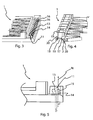
- Fig. 1 illustrates a modular flooring substrate 1 according to an embodiment.
- the modular flooring substrate comprises a rectangular frame 2 having an upper side U and a lower side L in use. In use the upper side U faces away from the foundation, e.g. floor, onto which the modular flooring substrate is placed.
- a surface material M (see Fig. 3 ) may be supported directly by the frame 2, and/or by a support structure 3 provided within the frame 2 for supporting the surface material M.
- the support structure 3, if any, may for example be a framework of injection molded plastic forming a light-weight and well-vented structure suitable for supporting the surface material M and distributing loads from the surface material M and down to an underlying surface, such as a concrete floor.
- the support structure 3 may be provided with lower vent channels 4 for allowing fluid, such as condensed water or air, to pass under and/or through the substrate 1. Also, the support structure 3 may be provided with a plurality of screw holes 5 distributed over the surface of the support structure 3 in predetermined positions for providing an easy way of attaching a surface material M suitable to be attached by screws, such as wood, plastics or metal. If there are pre-drilled holes in the surface material M to be attached, the position of the surface material M is given by the predetermined positions of the screw holes 5 in the support structure 3, effectively making production of flooring panels easier and more effective.
- guiding recesses/guiding protrusions 6 may be provided on the substrate 1 for receiving a flooring surface material M, such as wooden ribs, and keeping the flooring surface material M guided in a predetermined position during attachment to the substrate 1, thereby making production of the flooring panels easier and more effective.
- the frame 2 comprises four edge sections 7, 8, 9, 10.
- Each edge section 7, 8, 9, 10 extends along an outer edge of the frame 2 and comprises either a male connector 11 or a female connector 12.
- Two adjacent edge sections 9, 10 of the four edge sections 7, 8, 9, 10 comprise the male connector 11, and the other two edge sections 7, 8 of the four edge sections 7, 8, 9, 10 comprise the female connector 12.
- the male connector 11 comprises at least two parallel elongate ridges 13, 14 arranged at a distance from each other.
- the ridges 13, 14 protrude in a normal direction N of the upper U or lower L side of the substrate 1. Furthermore, the ridges 13, 14 extend along each respective edge section 9, 10.
- the distance D between the ridges 13, 14 give room for them to deform and bend without hindering each other, thereby allowing the ridges 13, 14 to function independently of each other, both as guiding means for guiding two adjacent flooring panels relatively each other, and as a snap locking means for securing two adjacent flooring panels to each other.
- the male connector 11 Since the ridges 13, 14 of the male connector 11 protrude essentially along a normal direction N of the upper U or lower L side, the male connector 11 is suitable for receiving a female connector 12 along the normal direction N, effectively allowing a substrate 1 to be attached to, and detached from, another substrate laying on a horizontal floor by a vertical relative movement between the substrates 1.
- This is of advantage when a substrate 1 is to be detached from the middle of a floor and the substrate 1 is connected to other substrates along its edges, since the substrate 1 to be removed can be separated from underlying male connectors by vertical movement without any need of sideway movements, and hence, without a need of removal of surrounding flooring substrates.
- peripheral flooring substrates one by one until the periphery of the flooring reaches the substrate to be removed from the middle of the floor
- Snap locking functionality of the male connector 11 is preferably provided by a protrusion 15 extending from the outer ridge 14 in a direction essentially parallel to the upper side U or the lower side L of the rectangular frame 2, as can be seen in Fig. 4 .
- protrusions for snap-locking may be provided on either of the ridges 13, 14, as can be seen in Fig. 4 .
- Having the protrusion on the outer ridge 14 is preferable from a production point-of-view if the substrate 1 is to be injection molded, since an undercut is easier to handle when on the outside of the substrate, by providing a side-core, than an undercut caused by a protrusion on the inner ridge 13 is.
- mold design is already made easier by the fact that the ridges 13, 14 are spaced apart, since a simple core for forming the space can be withdrawn, where after the ridges can bend into the space between the ridges during extraction of the molded substrate from the mold.
- snap-locking is not absolutely needed between the male connectors 11 and female connectors 12 of adjacent flooring panels. Rather, friction between the male and female connectors 11, 12 may be enough to keep the male and female connectors 11, 12 together. Also, gravity may be enough on its own to keep them together.
- the elongate ridge shape of the male connector 11 allows a female connector 12 to move slightly along the ridge (as long as no other geometries of the substrate hinder such movement), thereby enabling easier simultaneous detachment of connectors which are substantially perpendicular to each other, partly because friction tends to be lower during relative movement of surfaces than when the surfaces are stationary, but also because of the large simultaneous normal forces that may be applied to the ridges by exerting a force in a diagonal direction across the substrate, from a corner between two male or two female connectors towards an opposite corner.
- Such deformation will slightly deform the ridges of connectors adjacent the corner around a respective longitudinal axis through the base of the ridges, resulting in that normal forces of outer surfaces of the ridges act partly in a normal direction of the substrate, thereby helping detachment of the connection.
- the shape of the male connector 11 is especially advantageous when removing a flooring panel from the middle of a floor surface, as will be further described below.
- the male connector 11 may comprise at least one recess 16, such as a cut, along its extension.
- Such cuts or recesses 16 make the substrate 1 more flexible, which is of advantage during detachment of the male and female connectors 11, 12.
- recesses facilitate bending of the modular flooring substrate along the ridges which is also advantageous during detachment.
- local stress acting where the male and female connectors are about to detach from each other only acts on a limited length of connector and thereby more easily may deform that portion of the male connector 12 so that the male 11 and female 12 connectors more easily disconnect.
- the female connector 12 is shaped to fit with a corresponding male connector of another substrate.
- the female connector 12 of a first substrate 1 does not necessarily have to be designed to fit with a male connector having the same design and dimensions as the male connector 11 of the first substrate 1.
- a male connector having the same design and dimensions as the male connector 11 of the first substrate 1.
- the female connector 12 comprises one or more receiving recesses, or receiving members, shaped to fit a male connector 11.
- the female connector 12 may further comprise snap-locking recesses 20 (see Fig. 4 ) for receiving corresponding snap-locking protrusions 15 of the male connector 11.
- the one or more receiving recesses, or receiving members, of the female connector 12 comprise an inner wall 17 and an outer wall 18.
- the inner wall 17 is attached to, or integrated with, the frame 2.
- the outer wall 18 is attached to the inner wall 17 or to the frame 2, by means of one or more distance walls 19.
- the distance walls may either be provided in the form as cross-walls 19 (as shown in Figs 1, 2 and 4 ), or as a continuous body (not shown) extending as a 'bottom' of the female connector 12 for joining the outer and inner walls.
- the male connector 11 has to be provided with corresponding cuts or recesses 16.
- An advantage of having many cross-walls 18 is that the outer wall 18 does not have to be as rigid and therefore its dimensions can be kept down, which leads to a reduced material need. Another advantage is that the outer wall can act more evenly along the male connector 11 than what would have been possible without cross-walls 18, effectively leading to a more uniform connection.
- the male connector 11 is configured to be received by a female connector of 12 of a further modular flooring substrate, and vice versa.
- a female connector of 12 of a further modular flooring substrate When two modular flooring substrates are connected, one edge section of one of the flooring substrates will be superpositioned over the corresponding edge section of the further modular flooring substrate. This is illustrated in Fig. 7 . It should be understood that it is not essential which one of two connected edge sections comprise the male and the female connectors respectively, as long as one edge sections comprising one kind of connector, is always adjacent another edge section comprising the same kind (male or female) of connector.
- the flooring panels may be provided with sealing means 16 attached either to the flooring substrate 1 or to the surface material M, or to both, such that the sealing means 16 is positioned along at least one of the edges of the surface material M of the flooring panel when in use.
- the sealing means 16 is positioned, colored and shaped to look like ordinary grout when in use.
- the sealing means 16 should preferably be flexible enough to allow relative movement between flooring panels.
- the sealing means 16 may be a flange of silicone rubber or foamed rubber.
- Flooring panels according to the invention are assembled by laying out panels on a floor and attaching new panels to already laid panels one-by-one by bringing the connectors of a subsequently laid panel, on top of corresponding connectors of already laid panels.
- a vertical force is applied to move the female connector(s) onto the male connector(s). The applied force causes a vertical movement of the subsequently laid panel.
- the flooring substrate 1 In order to remove a flooring panel (a substrate with surface material) the flooring substrate 1 should be diagonally tilted by lifting a first corner of the flooring substrate 1 by applying to the flooring surface, or to the substrate, a force in a direction normal to the upper side of the substrate or of the flooring surface. The applied force will cause the connection between a male connector 11 of the modular flooring substrate 1 and a female connector of a further modular flooring substrate to release.
- the first corner is a corner between two adjacent edge sections, both of them being superpositioned and connected to corresponding edge sections of further connected modular flooring substrates, see Fig 7 .
- This corner is also the corner which is most easy to lift straight up and should be easy to find if you do not remember which corner it is.
- a standard suction cup can be used to apply the force.
- the substrate 1 shall be pulled away from a second corner opposite of the first corner in order to detach any remaining connections between the first modular flooring substrate and any other modular flooring substrate.
- the substrate is pulled away in a direction along the tilted substrate, from the second corner towards the first corner. It might help to slightly wiggle the substrate 1.
Landscapes
- Engineering & Computer Science (AREA)
- Architecture (AREA)
- Civil Engineering (AREA)
- Structural Engineering (AREA)
- Ceramic Engineering (AREA)
- Life Sciences & Earth Sciences (AREA)
- Wood Science & Technology (AREA)
- Chemical & Material Sciences (AREA)
- Floor Finish (AREA)
Priority Applications (3)
| Application Number | Priority Date | Filing Date | Title |
|---|---|---|---|
| PL10156683T PL2369090T3 (pl) | 2010-03-16 | 2010-03-16 | Modułowe podłoże podłogowe |
| EP10156683.4A EP2369090B1 (en) | 2010-03-16 | 2010-03-16 | Modular flooring substrate |
| PCT/SE2011/050287 WO2011115559A1 (en) | 2010-03-16 | 2011-03-16 | Modular flooring substrate and a method for removing the same |
Applications Claiming Priority (1)
| Application Number | Priority Date | Filing Date | Title |
|---|---|---|---|
| EP10156683.4A EP2369090B1 (en) | 2010-03-16 | 2010-03-16 | Modular flooring substrate |
Publications (2)
| Publication Number | Publication Date |
|---|---|
| EP2369090A1 EP2369090A1 (en) | 2011-09-28 |
| EP2369090B1 true EP2369090B1 (en) | 2015-10-07 |
Family
ID=42332819
Family Applications (1)
| Application Number | Title | Priority Date | Filing Date |
|---|---|---|---|
| EP10156683.4A Not-in-force EP2369090B1 (en) | 2010-03-16 | 2010-03-16 | Modular flooring substrate |
Country Status (3)
| Country | Link |
|---|---|
| EP (1) | EP2369090B1 (pl) |
| PL (1) | PL2369090T3 (pl) |
| WO (1) | WO2011115559A1 (pl) |
Cited By (4)
| Publication number | Priority date | Publication date | Assignee | Title |
|---|---|---|---|---|
| US10677275B1 (en) | 2019-02-18 | 2020-06-09 | Daltile Corporation | Floor element for forming a floor covering, a floor covering and a method for manufacturing a floor element |
| US11339576B2 (en) | 2019-09-17 | 2022-05-24 | Daltile Corporation | Floor element for forming a floor covering and a floor covering |
| US11359386B2 (en) | 2020-05-07 | 2022-06-14 | Dal-Tile Corporation | Floor element for forming a floor covering, a floor covering, and a method for manufacturing a floor element |
| US11559961B2 (en) | 2019-09-17 | 2023-01-24 | Daltile Corporation | Pressing equipment, a plant and a method for forming a floor element |
Families Citing this family (3)
| Publication number | Priority date | Publication date | Assignee | Title |
|---|---|---|---|---|
| US8806832B2 (en) | 2011-03-18 | 2014-08-19 | Inotec Global Limited | Vertical joint system and associated surface covering system |
| CN103758327B (zh) * | 2014-01-17 | 2016-04-20 | 黑龙江省木材科学研究所 | 一种带有二维网架结构的地板基材 |
| ES2902394T3 (es) * | 2017-05-15 | 2022-03-28 | Flooring Ind Ltd Sarl | Un elemento de suelo para formar un revestimiento de suelo y un revestimiento de suelo |
Family Cites Families (12)
| Publication number | Priority date | Publication date | Assignee | Title |
|---|---|---|---|---|
| US5323575A (en) * | 1993-06-01 | 1994-06-28 | Yeh Tzung Jzng | Tile and mounting mat assembly |
| SE522860C2 (sv) * | 2000-03-10 | 2004-03-09 | Pergo Europ Ab | Vertikalt förenade golvelement innefattande en kombination av olika golvelement |
| FR2826391A1 (fr) * | 2001-06-20 | 2002-12-27 | Arnaud Becker | Dispositif d'assemblage des bords de panneaux, lattes ou lambris |
| DE10295140D2 (de) * | 2001-11-28 | 2004-12-23 | Mayer Hans | Verlegesystem für Bodenplatten |
| US6802159B1 (en) * | 2002-05-31 | 2004-10-12 | Snap Lock Industries, Inc. | Roll-up floor tile system and the method |
| DE20215223U1 (de) | 2002-10-02 | 2003-02-27 | Kellner, Peter, 36269 Philippsthal | Fußboden aus einzelnen Elementen |
| BE1015239A3 (nl) * | 2002-12-09 | 2004-11-09 | Flooring Ind Ltd | Vloerpaneel en werkwijze voor het koppelen, respectievelijk ontkoppelen van vloerpanelen. |
| DK176537B1 (da) * | 2005-04-21 | 2008-07-21 | Inter Ikea Sys Bv | Gulv |
| US7543417B2 (en) * | 2005-10-04 | 2009-06-09 | Comc, Llc | Modular flooring assemblies |
| DK2009197T3 (en) * | 2006-04-14 | 2016-06-13 | Yekalon Ind Inc | Floor block, floor system and laying method therefore |
| WO2007129211A2 (en) * | 2006-05-10 | 2007-11-15 | Hermanus Petrus Alheit | Cladding product |
| US8037656B2 (en) * | 2008-08-08 | 2011-10-18 | Liu David C | Flooring boards with press down locking mechanism |
-
2010
- 2010-03-16 PL PL10156683T patent/PL2369090T3/pl unknown
- 2010-03-16 EP EP10156683.4A patent/EP2369090B1/en not_active Not-in-force
-
2011
- 2011-03-16 WO PCT/SE2011/050287 patent/WO2011115559A1/en not_active Ceased
Cited By (10)
| Publication number | Priority date | Publication date | Assignee | Title |
|---|---|---|---|---|
| US10677275B1 (en) | 2019-02-18 | 2020-06-09 | Daltile Corporation | Floor element for forming a floor covering, a floor covering and a method for manufacturing a floor element |
| US10731682B1 (en) | 2019-02-18 | 2020-08-04 | Daltile Corporation | Floor element for forming a floor covering, a floor covering and a method for manufacturing a floor element |
| US12152626B2 (en) | 2019-02-18 | 2024-11-26 | Dal-Tile, Llc | Floor element for forming a floor covering, a floor covering, and a method for manufacturing a floor element |
| US11339576B2 (en) | 2019-09-17 | 2022-05-24 | Daltile Corporation | Floor element for forming a floor covering and a floor covering |
| US11559961B2 (en) | 2019-09-17 | 2023-01-24 | Daltile Corporation | Pressing equipment, a plant and a method for forming a floor element |
| US12115748B2 (en) | 2019-09-17 | 2024-10-15 | Dal-Tile, Llc | Pressing equipment, a plant and a method for forming a floor element |
| US12584321B2 (en) | 2019-09-17 | 2026-03-24 | Dal-Tile, Llc | Floor element for forming a floor covering and a floor covering |
| US11359386B2 (en) | 2020-05-07 | 2022-06-14 | Dal-Tile Corporation | Floor element for forming a floor covering, a floor covering, and a method for manufacturing a floor element |
| US12018495B2 (en) | 2020-05-07 | 2024-06-25 | Dal-Tile, Llc | Floor element for forming a floor covering, a floor covering, and a method for manufacturing a floor element |
| US12366074B2 (en) | 2020-05-07 | 2025-07-22 | Dal-Tile, Llc | Floor element for forming a floor covering, a floor covering, and a method for manufacturing a floor element |
Also Published As
| Publication number | Publication date |
|---|---|
| PL2369090T3 (pl) | 2016-04-29 |
| WO2011115559A1 (en) | 2011-09-22 |
| EP2369090A1 (en) | 2011-09-28 |
Similar Documents
| Publication | Publication Date | Title |
|---|---|---|
| EP2369090B1 (en) | Modular flooring substrate | |
| CN102317553B (zh) | 模块式地板系统 | |
| US8887462B2 (en) | Prefabricated tile system with modular backing board | |
| US8640418B2 (en) | Surface covering system | |
| US9003736B2 (en) | System for a floor covering | |
| WO2005082081A3 (en) | Modular tile with controlled deflection | |
| US20060260223A1 (en) | Interlocking Frame System for Floor and Wall Structures | |
| US7908802B2 (en) | System for constructing tread surfaces | |
| US20170292259A1 (en) | A plastic infiltration unit, a system comprising a plurality of plastic infiltration units | |
| EP2351897A1 (en) | New type of plastic ground mat | |
| CN107002412B (zh) | 铺地模块 | |
| US20140144092A1 (en) | System and apparatus for installation of tile floor | |
| CN101313114B (zh) | 模块化地板组件 | |
| EP2199490A2 (en) | Removable surface covering | |
| EP1835832A1 (en) | Floor drainage | |
| MXPA06014208A (es) | Sistema de construccion para construir estructuras planas. | |
| EP2210995A1 (en) | Tile for covering surfaces | |
| US20140013694A1 (en) | Free floating sub-floor thermoplastic tile | |
| JP4558917B2 (ja) | 床化粧材用敷設枠 | |
| NL1044154B1 (en) | Tiling device | |
| US9206598B2 (en) | Construction block lock | |
| KR101499882B1 (ko) | 염전용 깔판받침대 및 그 깔판받침대의 시공방법 | |
| GB2189820A (en) | Brick or tile laying spacer aid | |
| JP3050701U (ja) | 連結敷設用床材 | |
| CN211229337U (zh) | 地板及地板总成 |
Legal Events
| Date | Code | Title | Description |
|---|---|---|---|
| PUAI | Public reference made under article 153(3) epc to a published international application that has entered the european phase |
Free format text: ORIGINAL CODE: 0009012 |
|
| AK | Designated contracting states |
Kind code of ref document: A1 Designated state(s): AT BE BG CH CY CZ DE DK EE ES FI FR GB GR HR HU IE IS IT LI LT LU LV MC MK MT NL NO PL PT RO SE SI SK SM TR |
|
| AX | Request for extension of the european patent |
Extension state: AL BA ME RS |
|
| 17P | Request for examination filed |
Effective date: 20120328 |
|
| GRAP | Despatch of communication of intention to grant a patent |
Free format text: ORIGINAL CODE: EPIDOSNIGR1 |
|
| INTG | Intention to grant announced |
Effective date: 20140702 |
|
| GRAS | Grant fee paid |
Free format text: ORIGINAL CODE: EPIDOSNIGR3 |
|
| RAP1 | Party data changed (applicant data changed or rights of an application transferred) |
Owner name: FLIGO FLOORING INNOVATION GROUP AB |
|
| GRAA | (expected) grant |
Free format text: ORIGINAL CODE: 0009210 |
|
| AK | Designated contracting states |
Kind code of ref document: B1 Designated state(s): AT BE BG CH CY CZ DE DK EE ES FI FR GB GR HR HU IE IS IT LI LT LU LV MC MK MT NL NO PL PT RO SE SI SK SM TR |
|
| REG | Reference to a national code |
Ref country code: GB Ref legal event code: FG4D |
|
| REG | Reference to a national code |
Ref country code: AT Ref legal event code: REF Ref document number: 753865 Country of ref document: AT Kind code of ref document: T Effective date: 20151015 Ref country code: CH Ref legal event code: EP |
|
| REG | Reference to a national code |
Ref country code: IE Ref legal event code: FG4D |
|
| REG | Reference to a national code |
Ref country code: DE Ref legal event code: R096 Ref document number: 602010028002 Country of ref document: DE |
|
| REG | Reference to a national code |
Ref country code: SE Ref legal event code: TRGR |
|
| REG | Reference to a national code |
Ref country code: NL Ref legal event code: MP Effective date: 20151007 |
|
| REG | Reference to a national code |
Ref country code: AT Ref legal event code: MK05 Ref document number: 753865 Country of ref document: AT Kind code of ref document: T Effective date: 20151007 |
|
| REG | Reference to a national code |
Ref country code: LT Ref legal event code: MG4D |
|
| PG25 | Lapsed in a contracting state [announced via postgrant information from national office to epo] |
Ref country code: ES Free format text: LAPSE BECAUSE OF FAILURE TO SUBMIT A TRANSLATION OF THE DESCRIPTION OR TO PAY THE FEE WITHIN THE PRESCRIBED TIME-LIMIT Effective date: 20151007 Ref country code: NO Free format text: LAPSE BECAUSE OF FAILURE TO SUBMIT A TRANSLATION OF THE DESCRIPTION OR TO PAY THE FEE WITHIN THE PRESCRIBED TIME-LIMIT Effective date: 20160107 Ref country code: LT Free format text: LAPSE BECAUSE OF FAILURE TO SUBMIT A TRANSLATION OF THE DESCRIPTION OR TO PAY THE FEE WITHIN THE PRESCRIBED TIME-LIMIT Effective date: 20151007 Ref country code: HR Free format text: LAPSE BECAUSE OF FAILURE TO SUBMIT A TRANSLATION OF THE DESCRIPTION OR TO PAY THE FEE WITHIN THE PRESCRIBED TIME-LIMIT Effective date: 20151007 Ref country code: NL Free format text: LAPSE BECAUSE OF FAILURE TO SUBMIT A TRANSLATION OF THE DESCRIPTION OR TO PAY THE FEE WITHIN THE PRESCRIBED TIME-LIMIT Effective date: 20151007 Ref country code: IS Free format text: LAPSE BECAUSE OF FAILURE TO SUBMIT A TRANSLATION OF THE DESCRIPTION OR TO PAY THE FEE WITHIN THE PRESCRIBED TIME-LIMIT Effective date: 20160207 Ref country code: IT Free format text: LAPSE BECAUSE OF FAILURE TO SUBMIT A TRANSLATION OF THE DESCRIPTION OR TO PAY THE FEE WITHIN THE PRESCRIBED TIME-LIMIT Effective date: 20151007 |
|
| PG25 | Lapsed in a contracting state [announced via postgrant information from national office to epo] |
Ref country code: GR Free format text: LAPSE BECAUSE OF FAILURE TO SUBMIT A TRANSLATION OF THE DESCRIPTION OR TO PAY THE FEE WITHIN THE PRESCRIBED TIME-LIMIT Effective date: 20160108 Ref country code: PT Free format text: LAPSE BECAUSE OF FAILURE TO SUBMIT A TRANSLATION OF THE DESCRIPTION OR TO PAY THE FEE WITHIN THE PRESCRIBED TIME-LIMIT Effective date: 20160208 Ref country code: LV Free format text: LAPSE BECAUSE OF FAILURE TO SUBMIT A TRANSLATION OF THE DESCRIPTION OR TO PAY THE FEE WITHIN THE PRESCRIBED TIME-LIMIT Effective date: 20151007 Ref country code: AT Free format text: LAPSE BECAUSE OF FAILURE TO SUBMIT A TRANSLATION OF THE DESCRIPTION OR TO PAY THE FEE WITHIN THE PRESCRIBED TIME-LIMIT Effective date: 20151007 Ref country code: FI Free format text: LAPSE BECAUSE OF FAILURE TO SUBMIT A TRANSLATION OF THE DESCRIPTION OR TO PAY THE FEE WITHIN THE PRESCRIBED TIME-LIMIT Effective date: 20151007 |
|
| REG | Reference to a national code |
Ref country code: DE Ref legal event code: R097 Ref document number: 602010028002 Country of ref document: DE |
|
| PG25 | Lapsed in a contracting state [announced via postgrant information from national office to epo] |
Ref country code: CZ Free format text: LAPSE BECAUSE OF FAILURE TO SUBMIT A TRANSLATION OF THE DESCRIPTION OR TO PAY THE FEE WITHIN THE PRESCRIBED TIME-LIMIT Effective date: 20151007 |
|
| PLBE | No opposition filed within time limit |
Free format text: ORIGINAL CODE: 0009261 |
|
| STAA | Information on the status of an ep patent application or granted ep patent |
Free format text: STATUS: NO OPPOSITION FILED WITHIN TIME LIMIT |
|
| PG25 | Lapsed in a contracting state [announced via postgrant information from national office to epo] |
Ref country code: DK Free format text: LAPSE BECAUSE OF FAILURE TO SUBMIT A TRANSLATION OF THE DESCRIPTION OR TO PAY THE FEE WITHIN THE PRESCRIBED TIME-LIMIT Effective date: 20151007 Ref country code: EE Free format text: LAPSE BECAUSE OF FAILURE TO SUBMIT A TRANSLATION OF THE DESCRIPTION OR TO PAY THE FEE WITHIN THE PRESCRIBED TIME-LIMIT Effective date: 20151007 Ref country code: SK Free format text: LAPSE BECAUSE OF FAILURE TO SUBMIT A TRANSLATION OF THE DESCRIPTION OR TO PAY THE FEE WITHIN THE PRESCRIBED TIME-LIMIT Effective date: 20151007 Ref country code: RO Free format text: LAPSE BECAUSE OF FAILURE TO SUBMIT A TRANSLATION OF THE DESCRIPTION OR TO PAY THE FEE WITHIN THE PRESCRIBED TIME-LIMIT Effective date: 20151007 Ref country code: BE Free format text: LAPSE BECAUSE OF NON-PAYMENT OF DUE FEES Effective date: 20160331 Ref country code: SM Free format text: LAPSE BECAUSE OF FAILURE TO SUBMIT A TRANSLATION OF THE DESCRIPTION OR TO PAY THE FEE WITHIN THE PRESCRIBED TIME-LIMIT Effective date: 20151007 |
|
| 26N | No opposition filed |
Effective date: 20160708 |
|
| REG | Reference to a national code |
Ref country code: FR Ref legal event code: PLFP Year of fee payment: 7 |
|
| PG25 | Lapsed in a contracting state [announced via postgrant information from national office to epo] |
Ref country code: MC Free format text: LAPSE BECAUSE OF FAILURE TO SUBMIT A TRANSLATION OF THE DESCRIPTION OR TO PAY THE FEE WITHIN THE PRESCRIBED TIME-LIMIT Effective date: 20151007 Ref country code: LU Free format text: LAPSE BECAUSE OF FAILURE TO SUBMIT A TRANSLATION OF THE DESCRIPTION OR TO PAY THE FEE WITHIN THE PRESCRIBED TIME-LIMIT Effective date: 20160316 |
|
| REG | Reference to a national code |
Ref country code: CH Ref legal event code: PL |
|
| PG25 | Lapsed in a contracting state [announced via postgrant information from national office to epo] |
Ref country code: SI Free format text: LAPSE BECAUSE OF FAILURE TO SUBMIT A TRANSLATION OF THE DESCRIPTION OR TO PAY THE FEE WITHIN THE PRESCRIBED TIME-LIMIT Effective date: 20151007 |
|
| REG | Reference to a national code |
Ref country code: IE Ref legal event code: MM4A |
|
| PG25 | Lapsed in a contracting state [announced via postgrant information from national office to epo] |
Ref country code: BE Free format text: LAPSE BECAUSE OF FAILURE TO SUBMIT A TRANSLATION OF THE DESCRIPTION OR TO PAY THE FEE WITHIN THE PRESCRIBED TIME-LIMIT Effective date: 20151007 |
|
| PG25 | Lapsed in a contracting state [announced via postgrant information from national office to epo] |
Ref country code: LI Free format text: LAPSE BECAUSE OF NON-PAYMENT OF DUE FEES Effective date: 20160331 Ref country code: IE Free format text: LAPSE BECAUSE OF NON-PAYMENT OF DUE FEES Effective date: 20160316 Ref country code: CH Free format text: LAPSE BECAUSE OF NON-PAYMENT OF DUE FEES Effective date: 20160331 |
|
| REG | Reference to a national code |
Ref country code: FR Ref legal event code: PLFP Year of fee payment: 8 |
|
| REG | Reference to a national code |
Ref country code: DE Ref legal event code: R082 Ref document number: 602010028002 Country of ref document: DE Representative=s name: GLAWE DELFS MOLL PARTNERSCHAFT MBB VON PATENT-, DE Ref country code: DE Ref legal event code: R081 Ref document number: 602010028002 Country of ref document: DE Owner name: FLIGO FLOORING INNOVATION GROUP AB, SE Free format text: FORMER OWNER: FLIGO FLOORING INNOVATION GROUP AB, KILLEBERG, SE |
|
| PG25 | Lapsed in a contracting state [announced via postgrant information from national office to epo] |
Ref country code: MT Free format text: LAPSE BECAUSE OF FAILURE TO SUBMIT A TRANSLATION OF THE DESCRIPTION OR TO PAY THE FEE WITHIN THE PRESCRIBED TIME-LIMIT Effective date: 20151007 |
|
| REG | Reference to a national code |
Ref country code: GB Ref legal event code: 732E Free format text: REGISTERED BETWEEN 20170914 AND 20170920 |
|
| REG | Reference to a national code |
Ref country code: FR Ref legal event code: PLFP Year of fee payment: 9 |
|
| PG25 | Lapsed in a contracting state [announced via postgrant information from national office to epo] |
Ref country code: CY Free format text: LAPSE BECAUSE OF FAILURE TO SUBMIT A TRANSLATION OF THE DESCRIPTION OR TO PAY THE FEE WITHIN THE PRESCRIBED TIME-LIMIT Effective date: 20151007 Ref country code: HU Free format text: LAPSE BECAUSE OF FAILURE TO SUBMIT A TRANSLATION OF THE DESCRIPTION OR TO PAY THE FEE WITHIN THE PRESCRIBED TIME-LIMIT; INVALID AB INITIO Effective date: 20100316 |
|
| PG25 | Lapsed in a contracting state [announced via postgrant information from national office to epo] |
Ref country code: MK Free format text: LAPSE BECAUSE OF FAILURE TO SUBMIT A TRANSLATION OF THE DESCRIPTION OR TO PAY THE FEE WITHIN THE PRESCRIBED TIME-LIMIT Effective date: 20151007 Ref country code: TR Free format text: LAPSE BECAUSE OF FAILURE TO SUBMIT A TRANSLATION OF THE DESCRIPTION OR TO PAY THE FEE WITHIN THE PRESCRIBED TIME-LIMIT Effective date: 20151007 Ref country code: MT Free format text: LAPSE BECAUSE OF FAILURE TO SUBMIT A TRANSLATION OF THE DESCRIPTION OR TO PAY THE FEE WITHIN THE PRESCRIBED TIME-LIMIT Effective date: 20160331 |
|
| PG25 | Lapsed in a contracting state [announced via postgrant information from national office to epo] |
Ref country code: BG Free format text: LAPSE BECAUSE OF FAILURE TO SUBMIT A TRANSLATION OF THE DESCRIPTION OR TO PAY THE FEE WITHIN THE PRESCRIBED TIME-LIMIT Effective date: 20151007 |
|
| PGFP | Annual fee paid to national office [announced via postgrant information from national office to epo] |
Ref country code: DE Payment date: 20200309 Year of fee payment: 11 Ref country code: PL Payment date: 20200303 Year of fee payment: 11 Ref country code: GB Payment date: 20200304 Year of fee payment: 11 Ref country code: SE Payment date: 20200312 Year of fee payment: 11 |
|
| PGFP | Annual fee paid to national office [announced via postgrant information from national office to epo] |
Ref country code: FR Payment date: 20200305 Year of fee payment: 11 |
|
| REG | Reference to a national code |
Ref country code: DE Ref legal event code: R119 Ref document number: 602010028002 Country of ref document: DE |
|
| GBPC | Gb: european patent ceased through non-payment of renewal fee |
Effective date: 20210316 |
|
| PG25 | Lapsed in a contracting state [announced via postgrant information from national office to epo] |
Ref country code: GB Free format text: LAPSE BECAUSE OF NON-PAYMENT OF DUE FEES Effective date: 20210316 Ref country code: FR Free format text: LAPSE BECAUSE OF NON-PAYMENT OF DUE FEES Effective date: 20210331 Ref country code: SE Free format text: LAPSE BECAUSE OF NON-PAYMENT OF DUE FEES Effective date: 20210317 Ref country code: DE Free format text: LAPSE BECAUSE OF NON-PAYMENT OF DUE FEES Effective date: 20211001 |
|
| PG25 | Lapsed in a contracting state [announced via postgrant information from national office to epo] |
Ref country code: PL Free format text: LAPSE BECAUSE OF NON-PAYMENT OF DUE FEES Effective date: 20210316 |