EP2368624A1 - Anlage und Verfahren zur Aufbereitung einer Flüssigkeit mittels Membrantechnik - Google Patents
Anlage und Verfahren zur Aufbereitung einer Flüssigkeit mittels Membrantechnik Download PDFInfo
- Publication number
- EP2368624A1 EP2368624A1 EP11159409A EP11159409A EP2368624A1 EP 2368624 A1 EP2368624 A1 EP 2368624A1 EP 11159409 A EP11159409 A EP 11159409A EP 11159409 A EP11159409 A EP 11159409A EP 2368624 A1 EP2368624 A1 EP 2368624A1
- Authority
- EP
- European Patent Office
- Prior art keywords
- evaluation unit
- unit
- yield
- stream
- pump
- Prior art date
- Legal status (The legal status is an assumption and is not a legal conclusion. Google has not performed a legal analysis and makes no representation as to the accuracy of the status listed.)
- Granted
Links
Images
Classifications
-
- B—PERFORMING OPERATIONS; TRANSPORTING
- B01—PHYSICAL OR CHEMICAL PROCESSES OR APPARATUS IN GENERAL
- B01D—SEPARATION
- B01D61/00—Processes of separation using semi-permeable membranes, e.g. dialysis, osmosis or ultrafiltration; Apparatus, accessories or auxiliary operations specially adapted therefor
- B01D61/02—Reverse osmosis; Hyperfiltration ; Nanofiltration
- B01D61/12—Controlling or regulating
-
- B—PERFORMING OPERATIONS; TRANSPORTING
- B01—PHYSICAL OR CHEMICAL PROCESSES OR APPARATUS IN GENERAL
- B01D—SEPARATION
- B01D61/00—Processes of separation using semi-permeable membranes, e.g. dialysis, osmosis or ultrafiltration; Apparatus, accessories or auxiliary operations specially adapted therefor
- B01D61/02—Reverse osmosis; Hyperfiltration ; Nanofiltration
- B01D61/06—Energy recovery
-
- C—CHEMISTRY; METALLURGY
- C02—TREATMENT OF WATER, WASTE WATER, SEWAGE, OR SLUDGE
- C02F—TREATMENT OF WATER, WASTE WATER, SEWAGE, OR SLUDGE
- C02F1/00—Treatment of water, waste water, or sewage
- C02F1/008—Control or steering systems not provided for elsewhere in subclass C02F
-
- C—CHEMISTRY; METALLURGY
- C02—TREATMENT OF WATER, WASTE WATER, SEWAGE, OR SLUDGE
- C02F—TREATMENT OF WATER, WASTE WATER, SEWAGE, OR SLUDGE
- C02F1/00—Treatment of water, waste water, or sewage
- C02F1/44—Treatment of water, waste water, or sewage by dialysis, osmosis or reverse osmosis
- C02F1/441—Treatment of water, waste water, or sewage by dialysis, osmosis or reverse osmosis by reverse osmosis
-
- B—PERFORMING OPERATIONS; TRANSPORTING
- B01—PHYSICAL OR CHEMICAL PROCESSES OR APPARATUS IN GENERAL
- B01D—SEPARATION
- B01D2311/00—Details relating to membrane separation process operations and control
- B01D2311/20—Power consumption
-
- B—PERFORMING OPERATIONS; TRANSPORTING
- B01—PHYSICAL OR CHEMICAL PROCESSES OR APPARATUS IN GENERAL
- B01D—SEPARATION
- B01D2313/00—Details relating to membrane modules or apparatus
- B01D2313/24—Specific pressurizing or depressurizing means
-
- C—CHEMISTRY; METALLURGY
- C02—TREATMENT OF WATER, WASTE WATER, SEWAGE, OR SLUDGE
- C02F—TREATMENT OF WATER, WASTE WATER, SEWAGE, OR SLUDGE
- C02F2103/00—Nature of the water, waste water, sewage or sludge to be treated
- C02F2103/08—Seawater, e.g. for desalination
-
- C—CHEMISTRY; METALLURGY
- C02—TREATMENT OF WATER, WASTE WATER, SEWAGE, OR SLUDGE
- C02F—TREATMENT OF WATER, WASTE WATER, SEWAGE, OR SLUDGE
- C02F2209/00—Controlling or monitoring parameters in water treatment
- C02F2209/005—Processes using a programmable logic controller [PLC]
-
- C—CHEMISTRY; METALLURGY
- C02—TREATMENT OF WATER, WASTE WATER, SEWAGE, OR SLUDGE
- C02F—TREATMENT OF WATER, WASTE WATER, SEWAGE, OR SLUDGE
- C02F2209/00—Controlling or monitoring parameters in water treatment
- C02F2209/02—Temperature
-
- C—CHEMISTRY; METALLURGY
- C02—TREATMENT OF WATER, WASTE WATER, SEWAGE, OR SLUDGE
- C02F—TREATMENT OF WATER, WASTE WATER, SEWAGE, OR SLUDGE
- C02F2209/00—Controlling or monitoring parameters in water treatment
- C02F2209/03—Pressure
-
- C—CHEMISTRY; METALLURGY
- C02—TREATMENT OF WATER, WASTE WATER, SEWAGE, OR SLUDGE
- C02F—TREATMENT OF WATER, WASTE WATER, SEWAGE, OR SLUDGE
- C02F2209/00—Controlling or monitoring parameters in water treatment
- C02F2209/05—Conductivity or salinity
-
- Y—GENERAL TAGGING OF NEW TECHNOLOGICAL DEVELOPMENTS; GENERAL TAGGING OF CROSS-SECTIONAL TECHNOLOGIES SPANNING OVER SEVERAL SECTIONS OF THE IPC; TECHNICAL SUBJECTS COVERED BY FORMER USPC CROSS-REFERENCE ART COLLECTIONS [XRACs] AND DIGESTS
- Y02—TECHNOLOGIES OR APPLICATIONS FOR MITIGATION OR ADAPTATION AGAINST CLIMATE CHANGE
- Y02A—TECHNOLOGIES FOR ADAPTATION TO CLIMATE CHANGE
- Y02A20/00—Water conservation; Efficient water supply; Efficient water use
- Y02A20/124—Water desalination
- Y02A20/131—Reverse-osmosis
Definitions
- the invention relates to a plant and a process for the treatment of a liquid, wherein a pump feeds a feed stream to a membrane unit and the membrane unit separates the feed stream into a permeate stream and a retentate stream, wherein the actual value of the yield of the plant as a ratio of permeate to feed stream results and the retentate stream is fed to an energy recovery unit, wherein measured values are acquired via at least one sensor and forwarded to an evaluation unit.
- Membrane separation has become particularly established in food technology, biotechnology and pharmacy. Depending on the type of membranes used, the selective separation of individual substances or mixtures of substances is possible.
- a pump delivers the still untreated fluid, called the feed stream, to a membrane unit.
- Membrane units can be modularly built so that the system can be gradually adjusted to the extent of a separation problem.
- the separation takes place by means of a semipermeable membrane.
- the pump builds up a pressure in front of the semipermeable membrane. The solvent and often a part of the solutes are pressed through the membrane.
- the size of the retained substances can be adjusted. Depending on the size of the retained molecules, a distinction is made between microfiltration, ultrafiltration, nanofiltration and reverse osmosis.
- the invention for performing a reverse osmosis, in particular for seawater desalination.
- a reverse osmosis in particular for seawater desalination.
- RO reverse osmosis
- the desalination of seawater today offers a good opportunity to provide drinking water in freshwater regions with marine access cost in sufficient quantity. Often, smaller pumping stations are required, as a trend towards decentralized systems is emerging as a self-sufficient drinking water supply.
- the production capacity of the plant according to the invention is preferably less than 1000 m 3 permeate per day.
- the yield of the plant is called the ratio of Permeate to feedstream. The actual value of the yield can be determined by measuring the permeate stream and the feed stream.
- a certain working pressure must be applied on the side of the seawater.
- This pressure is provided by means of a high-pressure pump.
- pump types There are a variety of pump types that can generate the necessary pressure. Most commonly used are positive displacement pumps, in particular piston or diaphragm pumps, and centrifugal pumps.
- the retentate stream is fed to an energy recovery unit after leaving the membrane unit. This serves to recover the potential energy present in the retentate. By returning this energy, it is possible to reduce the energy demand of a seawater desalination plant.
- Various configurations of pumps and energy recovery units are in use. A widely used form is a configuration with a booster pump and a pressure exchanger.
- Membrane processes for the treatment of liquids are often automated. Sensors record measured values and forward them to an evaluation unit.
- the sensors are sensors or probes.
- the measured quantities are recorded by means of physical or chemical effects and converted into further processable quantities, mostly electrical signals.
- transducer, or measurand sensor is understood as the part of a measuring device that is directly responsive to a measured variable.
- the evaluation unit can control individual components of the system.
- evaluation units commercially available regulators, such as PID controller can be used.
- PLC programmable logic controller
- the WO 2007/090406 A1 shows a reverse osmosis system for providing fresh water from salt water.
- a pump brings the salt water to the in a membrane unit required pressure. After the membrane unit, the retentate flows through a pressure recovery unit.
- the pressure recovery unit is connected to a pump.
- Pressure sensors measure the pressure before entry of the feed stream into the membrane units and after exit of the retentate stream from the membrane units.
- the speed of rotation of an engine operatively connected to the pump and the pressure recovery unit is regulated as a function of the difference in these pressures. In such state-of-the-art plant controls, many factors that affect the reverse osmosis process are not taken into account.
- the object of the invention is to provide a system for plants for the treatment of liquids by membrane separation process available, which contributes to a reduction of operating costs.
- the evaluation unit determines a setpoint optimum yield at which the system can operate with a minimum specific energy requirements, the evaluation unit calculates the deviation of the actual value of the target value and varies depending on this deviation, the yield.
- the evaluation unit determines the optimum yield at which the system can be operated with a minimum specific energy requirement. According to the invention, the optimal yield for the specific energy requirement is used as the reference variable.
- the main factors influencing the specific energy requirements of the plant are the delivery pressure, the friction losses, the efficiency of the pump and the recovery unit, the yield and the retention.
- the efficiency curve of the pump and the energy recovery unit is determined by means of a test run of the pump and expressed as a function of the delivery pressure.
- the required delivery pressure is determined.
- a function is provided for the specific energy consumption of the plant, which depends on the yield, the temperature and the salt content.
- the efficiency curve ⁇ P of the pump and the efficiency curve ⁇ T of the energy recovery unit are taken into account for producing the functional relationship between the specific energy requirement P 'of the system and the yield ⁇ .
- the efficiency curves can be determined by means of a test run of the pump and / or the energy recovery unit at plant commissioning by the respective efficiency of the pump and / or the energy recovery unit is determined at different pressures.
- the efficiency of the pump and the energy recovery unit is equal to the ratio of delivered power to absorbed power.
- an electrical power value and a power value corresponding to the hydraulic conditions are determined at different pressures.
- the efficiency curve of the pump ⁇ P and the efficiency curve of the energy recovery unit ⁇ T are used. Furthermore, the friction pressure in piping and the membrane unit ⁇ p R are taken into account.
- the osmotic pressure at the end of the membrane unit is indicated by the term b ⁇ w F ⁇ ⁇ 1 + ⁇ ⁇ R dead 1 - ⁇ considered.
- R dead 1 - w P w F ⁇ A Efficiency coefficient [ bar -B ] b Osmotic coefficient b ' Osmotic constant (at 25 ° C) B Efficiency coefficient [-] k safety factor [-] P ' Specific energy requirement R dead Retention of the membrane [-] T temperature [ K ] ⁇ p R Pressure loss due to friction [bar] ⁇ yield [-] P R Dense retentate W P Mass fraction of salt permeate [Wt .-%] W Fa Mass fraction of salt Feed [Wt .-%] ⁇ P Efficiency of the pump [-] ⁇ T Efficiency of the energy recovery unit [-] P Delivery pressure of the pump [ bar ] P E Relaxation pressure of the energy recovery unit [ bar ]
- the evaluation unit determines the yield at which the system has a minimum specific energy requirement.
- the specific energy requirement P ' is based on the permeate.
- the yield is varied over the absorption volume of the energy recovery unit.
- the stroke and / or the displacement of the energy recovery unit can be varied. It is also envisaged to vary the yield over the displacement volume of the pump.
- positive displacement pumps are preferably used in which the stroke and / or the displacement chamber are varied.
- the evaluation unit determines the minimum of the energy consumption by means of an algorithm which calculates the minimum of the function via an extreme value calculation.
- the specific energy requirement of the plant is derived from the yield and the extreme value calculation is carried out.
- this optimum yield determined by calculating the extreme value serves as a reference variable for controlling the plant.
- the evaluation unit calculates the deviation of the actual value from the setpoint. Depending on this deviation, the displacement volume of the pump, in particular the stroke of the pump, and / or the absorption volume of the energy recovery unit, in particular the stroke of the energy recovery unit, regulated. With centrifugal pumps, a blade adjustment of the wheels can lead to change and / or regulation of the volume flow.
- the motor is preferably equipped with a frequency converter.
- the frequency converter also serves to protect the membrane when the pump starts up.
- the temperature and the salt content are measured in the feed stream and forwarded to the evaluation unit.
- the measurement is carried out with sensors that are positioned in a supply line in front of the pump.
- the pressure of the liquid is much lower in front of the pump than after the pump.
- low pressure gauges can be used that are cheaper than sensors that are designed for high pressures.
- the pressure of the feed stream is detected at the inlet to the membrane unit.
- the pump has brought the liquid to the pressure level required for reverse osmosis. Pressure losses have not yet occurred at this point.
- the pressure of the retentate stream at the exit from the membrane unit can be measured before the retentate enters the energy recovery unit.
- the signals from the sensors are forwarded to the evaluation unit.
- the evaluation unit calculates the pressure loss in the membrane unit, which results as the difference between the two detected pressures.
- the pressure of the retentate stream is detected after the energy recovery unit by means of a sensor and also forwarded to the evaluation unit. This allows the degree of energy recovery to be determined.
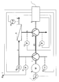
- Fig. 1 shows a schematic representation of a plant for seawater treatment.
- a pump 1 supplies a feed stream 2 to a membrane unit 3.
- the membrane unit 3 separates the feed stream 2 into a permeate stream 4 and a retentate stream 5.
- the retentate stream 5 is subsequently fed to an energy recovery unit 6.
- a sensor 10 detects the salinity and the temperature of the feed stream 2 before the pump 1. In addition, the pressure of the liquid before the pump 1 can be measured. All measured values are forwarded to the evaluation unit 7.
- a safety valve 16 prevents the pressure in front of the membrane unit 3 from assuming impermissibly high values.
- the evaluation unit 7 determines the optimum yield at which the system should be operated. To determine the actual yield, the feed stream 2 and the permeate stream 4 can likewise be measured and their measured values forwarded to the evaluation unit 7. The evaluation unit 7 calculates the actual value of the yield as a ratio of permeate stream 4 to feed stream 2. Furthermore, the evaluation unit 7 determines by means of an algorithm optimal yield as a target value at which the system can be operated with a minimum energy requirement. The deviation of the actual value from the setpoint results in a control difference.
- the absorption volume of the energy recovery unit 6 is varied, for example, via its stroke as a function of this control difference.
- the displacement volume of the pump 1, for example via the stroke of the pump 1 can be varied in order to optimize the yield.
- the speed of the motor 9 can be varied.
- the motor 9 of the pump 1 is provided with a frequency converter 8.
- the evaluation unit 7 is in operative connection with the frequency converter 8.
- a sensor 11 detects the pressure in the feed line of the feed stream 2 from the pump 1 to the membrane unit 3.
- a further sensor 12 measures the pressure in the discharge line of the retentate 5 from the membrane unit 3 to the energy recovery unit 6.
- the energy recovery unit 6 is connected via a connecting element 13 in operative connection with the pump 1.
- a sensor 14 By means of a sensor 14, the salt content and the pressure in the permeate stream 4 is detected, the membrane unit 3 leaves.
- Another sensor 15 measures the pressure of the retentate stream 5 after the energy recovery unit 6. About the energy recovery unit 6, the relaxation pressure pE decreases.
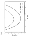
- the specific energy consumption has a minimum with a yield ⁇ of about 40%.
- W Fa 35000 mg / L
- the minimum of specific energy consumption shifts by approximately 0.2 kWh / t when the total salt concentration changes by 5000 mg / L.
Landscapes
- Engineering & Computer Science (AREA)
- Water Supply & Treatment (AREA)
- Chemical & Material Sciences (AREA)
- Life Sciences & Earth Sciences (AREA)
- Hydrology & Water Resources (AREA)
- Environmental & Geological Engineering (AREA)
- Organic Chemistry (AREA)
- Nanotechnology (AREA)
- Chemical Kinetics & Catalysis (AREA)
- Separation Using Semi-Permeable Membranes (AREA)
Abstract
Description
- Die Erfindung betrifft eine Anlage und ein Verfahren zur Aufbereitung einer Flüssigkeit, wobei eine Pumpe einen Feedstrom einer Membraneinheit zuführt und die Membraneinheit den Feedstrom in einen Permeatstrom und einen Retentatstrom trennt, wobei sich der Istwert der Ausbeute der Anlage als Verhältnis von Permeatstrom zu Feedstrom ergibt und der Retentatstrom einer Energierückgewinnungseinheit zugeführt wird, wobei über mindestens einen Sensor Messwerte erfasst und an eine Auswerteeinheit weitergeleitet werden.
- Zur Herstellung von zahlreichen Produkten ist eine Aufbereitung von Flüssigkeiten notwendig. Bei Anlagen und Verfahren entsprechend dem Oberbegriff der Erfindung werden dazu Membrantrennverfahren eingesetzt. Deren besonderer Vorteil besteht darin, dass sie ohne Erhitzen auskommen und somit meist energetisch günstiger sind als thermische Trennverfahren. In der Membrantechnik fallen zwei Fraktionen an, die als Retentat und Permeat bezeichnet werden. Der Retentatstrom wird beim Trennprozess von der Membran zurückgehalten. Den Anteil der Flüssigkeit, der durch die Membran durchtritt, bezeichnet man als Permeat.
- Die Separation mittels Membranverfahren hat sich insbesondere in der Lebensmitteltechnologie, der Biotechnologie und der Pharmazie etabliert. Je nach Art der verwendeten Membranen ist die selektive Abtrennung einzelner Stoffe oder bestimmter Stoffgemische möglich.
- Man unterscheidet die Membrantrennverfahren nach der treibenden Kraft, die der Trennung zugrunde liegt. Bei der vorliegenden Erfindung handelt es sich um druckgetriebene Prozesse, bei denen vorzugsweise Wasser als Lösungsmittel eingesetzt wird.
- Eine Pumpe führt die noch unbehandelte Flüssigkeit, die als Feedstrom bezeichnet wird, einer Membraneinheit zu. Membraneinheiten lassen sich modular aufbauen, so dass die Anlage stufenweise an den Umfang eines Trennproblems angepasst werden kann. Die Trennung erfolgt mittels einer semipermeablen Membran. Die Pumpe baut einen Druck vor der semipermeablen Membran auf. Dabei werden das Lösungsmittel und häufig ein Teil der gelösten Stoffe durch die Membran gepresst.
- Über die Auswahl der Membran lässt sich die Größe der zurückgehaltenen Stoffe einstellen. Je nach Größe der zurückgehaltenen Moleküle unterscheidet man zwischen Mikrofiltration, Ultrafiltration, Nanofiltration und Umkehrosmose.
- Als besonders günstig erweist sich der Einsatz der Erfindung zur Durchführung einer Umkehrosmose, insbesondere zur Meerwasserentsalzung. Wird die konzentrierte Lösung mit einem Druck beaufschlagt, der oberhalb des osmotischen Drucks liegt, diffundieren Wassermoleküle durch die Membran, während die gelösten Salze zurückgehalten werden. Somit wird auf der einen Seite die Salzlösung aufkonzentriert, während auf der anderen Seite salzarmes Wasser gewonnen wird. Zwischen dem angelegten Betriebsdruck und dem sich einstellenden osmotischen Druck stellt sich ein Gleichgewicht ein. Dieser Prozess wird als Umkehrosmose (engl. Reverse Osmosis - RO) bezeichnet und zur Meerwasserentsalzung genutzt.
- Die Meerwasserentsalzung bietet heutzutage eine gute Möglichkeit, Trinkwasser in süßwasserarmen Regionen mit Meeresanbindung kostengünstig in ausreichender Menge zur Verfügung zu stellen. Häufig werden kleinere Pumpanlagen benötigt, da sich ein Trend zur dezentralen Anlage als autarke Trinkwasserversorgung abzeichnet. Die Produktionskapazität der erfindungsgemäßen Anlage beträgt vorzugsweise weniger als 1000 m3 Permeat pro Tag. Als Ausbeute der Anlage bezeichnet man das Verhältnis von Permeat- zu Feedstrom. Der Istwert der Ausbeute kann durch Messung des Permeatstroms und des Feedstroms bestimmt werden.
- Damit eine Umkehrosmose stattfindet und somit ausreichend Trinkwasser produziert wird, muss ein gewisser Arbeitsdruck auf der Seite des Meerwassers aufgebracht werden. Dieser Druck wird mittels einer Hochdruckpumpe bereitgestellt. Es gibt eine Vielzahl von Pumpenarten, die den nötigen Druck erzeugen können. Am häufigsten werden Verdrängerpumpen, insbesondere Kolben- oder Membranpumpen, und Kreiselpumpen verwendet.
- Der Retentatstrom wird nach Verlassen der Membraneinheit einer Energierückgewinnungseinheit zugeführt. Diese dient der Rückgewinnung der im Retentat vorhandenen potentiellen Energie. Durch das Zurückführen dieser Energie ist es möglich, den Energiebedarf einer Meerwasserentsalzungsanlage zu verringern. Dabei sind unterschiedlichste Konfigurationen von Pumpen und Energierückgewinnungseinheiten im Einsatz. Eine weit verbreitete Form ist eine Konfiguration mit einer Booster-Pumpe und einem Drucktauscher.
- Membranverfahren zur Aufbereitung von Flüssigkeiten sind häufig automatisiert. Über Sensoren werden Messwerte erfasst und an eine Auswerteeinheit weitergeleitet. Bei den Sensoren handelt es sich um Messaufnehmer bzw. Messfühler. Die Messgrößen werden mittels physikalischer oder chemischer Effekte erfasst und in weiterverarbeitbare Größen, meist elektrische Signale, umgeformt. Der Begriff Aufnehmer, bzw. Messgrößen-Aufnehmer, wird verstanden als der Teil einer Messeinrichtung, der auf eine Messgröße unmittelbar anspricht.
- Die Auswerteeinheit kann einzelne Komponenten der Anlage ansteuern. Als Auswerteeinheiten können handelsübliche Regler, beispielsweise PID-Regler, eingesetzt werden. Auch der Einsatz einer speicherprogrammierbaren Steuerung (SPS) ist möglich.
- Die
WO 2007/090406 A1 zeigt eine Umkehrosmose-Anlage zur Bereitstellung von Süßwasser aus Salzwasser. Eine Pumpe bringt das Salzwasser auf den in einer Membraneinheit erforderlichen Druck. Nach der Membraneinheit fließt das Retentat durch eine Druckrückgewinnungseinheit. Die Druckrückgewinnungseinheit ist mit einer Pumpe verbunden. Über Drucksensoren wird der Druck vor Eintritt des Feedstroms in die Membraneinheiten und nach Austritt des Retentatstroms aus den Membraneinheiten gemessen. Die Drehzahl eines Motors, der in Wirkverbindung mit der Pumpe und der Druckrückgewinnungseinheit steht, wird in Abhängigkeit der Differenz dieser Drücke geregelt. Bei solchen Anlageregelungen, nach dem Stand der Technik, werden zahlreiche Faktoren, welche den Umkehrosmose Prozess beeinflussen, nicht berücksichtigt. - Aufgabe der Erfindung ist es, eine Regelung für Anlagen zur Aufbereitung von Flüssigkeiten durch Membrantrennverfahren zur Verfügung zu stellen, die zu einer Reduzierung der Betriebskosten beiträgt.
- Diese Aufgabe wird erfindungsgemäß dadurch gelöst, dass die Auswerteeinheit als Sollwert eine optimale Ausbeute ermittelt, bei der sich die Anlage mit einem minimalen spezifischen Energiebedarf betreiben lässt, wobei die Auswerteeinheit die Abweichung des Istwerts vom Sollwert errechnet und in Abhängigkeit dieser Abweichung, die Ausbeute variiert.
- Bei der vorliegenden Erfindung ermittelt die Auswerteeinheit die optimale Ausbeute, bei der sich die Anlage mit einem minimalen spezifischen Energiebedarf betreiben lässt. Erfindungsgemäß wird die für den spezifischen Energiebedarf optimale Ausbeute als Führungsgröße zugrunde gelegt.
- Als wesentliche Einflussparameter auf den spezifischen Energiebedarf der Anlage werden der Förderdruck, die Reibungsverluste, der Wirkungsgrad der Pumpe und der Rückgewinnungseinheit, die Ausbeute und der Rückhalt herangezogen.
- Zur Herstellung eines funktionalen Zusammenhangs zwischen dem spezifischen Energiebedarf der Anlage und der Ausbeute, wird der Wirkungsgradverlauf der Pumpe und der Energierückgewinnungseinheit mittels eines Testlaufes der Pumpe bestimmt und als Funktion des Förderdrucks ausgedrückt. Mittels des osmotischen Druckes und den Reibungsverlusten wird der erforderliche Förderdruck bestimmt. Erfindungsgemäß wird eine Funktion für den spezifischen Energieverbrauch der Anlage bereitgestellt, die von der Ausbeute, der Temperatur und dem Salzgehalt abhängt.
- Erfindungsgemäß werden zur Herstellung des funktionalen Zusammenhangs zwischen dem spezifischen Energiebedarf P' der Anlage und der Ausbeute Φ der Wirkungsgradverlauf ηP der Pumpe und der Wirkungsgradverlauf η T der Energierückgewinnungseinheit berücksichtigt. Die Wirkungsgradverläufe lassen sich mittels eines Testlaufes der Pumpe und/oder der Energierückgewinnungseinheit bei Anlageninbetriebnahme bestimmen, indem zu verschiedenen Drücken der jeweilige Wirkungsgrad der Pumpe und/oder der Energierückgewinnungseinheit ermittelt wird. Der Wirkungsgrad der Pumpe und der Energierückgewinnungseinheit entspricht dem Verhältnis von abgegebener Leistung zu aufgenommener Leistung. Idealerweise wird dabei bei verschiedenen Drücken jeweils ein elektrischer Leistungswert sowie ein den hydraulischen Gegebenheiten entsprechender Leistungswert ermittelt. Alternativ ist es vorgesehen, bereits bekannte Wirkungsgradverläufe der Pumpe und/oder der Energierückgewinnungseinheit zu verwenden. Der Wirkungsgradverlauf der Pumpe wird vorzugsweise mit der Formel

als Funktion des Förderdrucks p der Pumpe ausgedrückt, wobei A und B als Wirkungsgrad-Koeffizienten zweckmäßigerweise numerisch ermittelt werden. Dabei ist A ein positiver Wert und B ein negativer Wert. Der Wirkungsgradverlauf der Energierückgewinnungseinheit wird vorteilhaft mittels gleicher Werte A und B angenähert, wobei anstelle des Förderdruckes p der Entspannungsdruck pE , der über die Energierückgewinnungseinheit abgebaut wird, verwendet wird:
- In den Zusammenhang für den spezifischen Energiebedarf P'

- werden der Wirkungsgradverlauf der Pumpe ηP und der Wirkungsgradverlauf der Energierückgewinnungseinheit η T eingesetzt. Weiterhin werden der Reibungsdruck in Rohrleitungen und der Membraneinheit ΔpR berücksichtigt. Der osmotische Druck am Ende der Membraneinheit wird durch den Term

berücksichtigt. - Ein funktionaler Zusammenhang zwischen dem spezifischen Energiebedarf und der Ausbeute wird vorzugsweise über die folgende Gleichung hergestellt:

- Im osmotischen Koeffizienten b ist die Temperatur T berücksichtigt. Ein zweckmäßiger Zusammenhang ist durch folgende Gleichung gegeben:

- Dabei ist R tot als Rückhalt der Membran gegeben durch:

A Wirkungsgrad Koeffizient [bar-B ] b Osmotischer Koeffizient 
b' Osmotische Konstante (bei 25°C) 
B Wirkungsgrad Koeffizient [-] k Sicherheitsfaktor [-] P' Spezifischer Energiebedarf 
Rtot Rückhalt der Membran [-] T Temperatur [K] ΔpR Druckverlust durch Reibung [bar] Φ Ausbeute [-] PR Dichte Retentat 
WP Massenanteil Salz Permeat [Gew.-%] WFa Massenanteil Salz Feed [Gew.-%] η P Wirkungsgrad der Pumpe [-] η T Wirkungsgrad der Energierückgewinnungseinheit [-] P Förderdruck der Pumpe [bar] P E Entspannungsdruck der Energierückgewin-nungseinheit [bar] - Die Auswerteeinheit ermittelt zu dieser Funktion die Ausbeute, bei welcher die Anlage einen minimalen spezifischen Energiebedarf besitzt.
- Der spezifische Energiebedarf P' ist dabei auf das Permeat bezogen.
- Bei einer besonders vorteilhaften Ausgestaltung der Erfindung wird die Ausbeute über das Schluckvolumen der Energierückgewinnungseinheit variiert. Dazu kann der Hub und/oder der Verdrängerraum der Energierückgewinnungseinheit variiert werden. Ebenfalls ist es vorgesehen, die Ausbeute über das Verdrängungsvolumen der Pumpe zu variieren. Dazu werden vorzugsweise Verdrängerpumpen eingesetzt, bei denen der Hub und/oder der Verdrängerraum variiert werden.
- Bei einer besonders vorteilhaften Variante der Erfindung ermittelt die Auswerteeinheit das Minimum des Energieverbrauchs mittels eines Algorithmus, der über eine Extremwertberechnung das Minimum der Funktion errechnet. Um die optimale Ausbeute hinsichtlich der Energieeffizienz herauszufinden, wird der spezifische Energiebedarf der Anlage nach der Ausbeute abgeleitet und die Extremwertberechnung durchgeführt.
- Erfindungsgemäß dient diese, durch Extremwertberechnung ermittelte, optimale Ausbeute als Führungsgröße zur Steuerung der Anlage. In einem nächsten Schritt errechnet die Auswerteeinheit die Abweichung des Istwerts vom Sollwert. In Abhängigkeit dieser Abweichung werden das Verdrängungsvolumen der Pumpe, insbesondere der Hub der Pumpe, und/oder das Schluckvolumen der Energierückgewinnungseinheit, insbesondere der Hub der Energierückgewinnungseinheit, geregelt. Bei Kreiselpumpen kann eine Schaufelverstellung der Laufräder zur Änderung und/oder Regelung des Volumenstroms führen.
- Bei Kreiselpumpen und bei Verdrängerpumpen kann zusätzlich eine Regelung des Volumenstroms und/oder des Druckes über die Drehzahl des Motors, der die Pumpe antreibt, erfolgen. Dazu ist der Motor vorzugsweise mit einem Frequenzumrichter ausgestattet. Der Frequenzumrichter dient zusätzlich beim Anfahren der Pumpe dazu, die Membran zu schonen.
- Bei einer besonders vorteilhaften Ausführung der Erfindung werden die Temperatur und der Salzgehalt im Feedstrom gemessen und an die Auswerteeinheit weitergeleitet. Vorzugsweise erfolgt die Messung mit Sensoren, die in einer Zuleitung vor der Pumpe positioniert sind. Der Druck der Flüssigkeit ist vor der Pumpe deutlich geringer als nach der Pumpe. Dadurch können Niederdruckmessgeräte eingesetzt werden, die preiswerter sind als Sensoren, die für hohe Drücke ausgelegt sind.
- Bei einer besonders günstigen Ausführung der Erfindung wird der Druck des Feedstroms am Eintritt in die Membraneinheit erfasst. An dieser Stelle hat die Pumpe die Flüssigkeit auf das für die Umkehrosmose erforderliche Druckniveau gebracht. Druckverluste sind an dieser Stelle noch nicht aufgetreten. Weiterhin kann der Druck des Retentatstroms am Austritt aus der Membraneinheit gemessen werden, bevor das Retentat in die Energierückgewinnungseinheit eintritt. Die Signale der Sensoren werden an die Auswerteeinheit weitergeleitet. Die Auswerteeinheit errechnet den Druckverlust in der Membraneinheit, der sich als Differenz der beiden erfassten Drücke ergibt.
- Bei einer weiteren Variante der Erfindung wird mittels eines Sensors der Druck des Retentatstroms nach der Energierückgewinnungseinheit erfasst und ebenfalls an die Auswerteeinheit weitergeleitet. Dadurch kann der Grad der Energierückgewinnung ermittelt werden.
- Weitere Merkmale und Vorteile der Erfindung ergeben sich aus der Beschreibung eines Ausführungsbeispiels anhand von Zeichnungen und aus den Zeichnungen selbst. Dabei zeigt
- Fig. 1
- eine schematische Darstellung der Anlage,
- Fig. 2
- ein Diagramm, in dem die spezifische Energie in Abhängigkeit der Ausbeute bei zwei verschiedenen Salzkonzentrationen im Feed aufgetragen ist.
-
Fig. 1 zeigt eine schematische Darstellung einer Anlage zur Meerwasseraufbereitung. Eine Pumpe 1 führt einen Feedstrom 2 einer Membraneinheit 3 zu. Die Membraneinheit 3 trennt den Feedstrom 2 in einen Permeatstrom 4 und einen Retentatstrom 5. Der Retentatstrom 5 wird anschließend einer Energierückgewinnungseinheit 6 zugeführt. - Ein Sensor 10 erfasst den Salzgehalt und die Temperatur des Feedstroms 2 vor der Pumpe 1. Zusätzlich kann der Druck der Flüssigkeit vor der Pumpe 1 gemessen werden. Sämtliche Messwerte werden an die Auswerteeinheit 7 weitergeleitet. Ein Sicherheitsventil 16 verhindert, dass der Druck vor der Membraneinheit 3 unzulässig hohe Werte annimmt.
- Die Auswerteeinheit 7 ermittelt die optimale Ausbeute, bei der die Anlage betrieben werden sollte. Zur Ermittlung der tatsächlichen Ausbeute können der Feedstrom 2 und der Permeatstrom 4 ebenfalls gemessen werden und deren Messwerte an die Auswerteeinheit 7 weitergeleitet werden. Die Auswerteeinheit 7 errechnet den Istwert der Ausbeute als Verhältnis von Permeatstrom 4 zu Feedstrom 2. Weiterhin ermittelt die Auswerteeinheit 7 mittels eines Algorithmus eine optimale Ausbeute als Sollwert, bei der die Anlage mit einem minimalen Energiebedarf betrieben werden kann. Die Abweichung des Istwertes vom Sollwert ergibt eine Regeldifferenz.
- Das Schluckvolumen der Energierückgewinnungseinheit 6 wird beispielsweise über deren Hub in Abhängigkeit dieser Regeldifferenz variiert. Alternativ oder ergänzend kann auch das Verdrängungsvolumen der Pumpe 1, beispielsweise über den Hub der Pumpe 1, variiert werden, um die Ausbeute zu optimieren.
- Weiterhin kann die Drehzahl des Motors 9 variiert werden. Der Motor 9 der Pumpe 1 ist mit einem Frequenzumrichter 8 versehen. Die Auswerteeinheit 7 steht in Wirkverbindung mit dem Frequenzumrichter 8.
- Bei der in
Fig. 1 dargestellten Anlage erfasst ein Sensor 11 den Druck in der Zuführleitung des Feedstroms 2 von der Pumpe 1 zur Membraneinheit 3. Ein weiterer Sensor 12 misst den Druck in der Abführleitung des Retentatstroms 5 von der Membraneinheit 3 zur Energierückgewinnungseinheit 6. Die Energierückgewinnungseinheit 6 steht über ein Verbindungselement 13 in Wirkverbindung mit der Pumpe 1. Mittels eines Sensors 14 wird der Salzgehalt und der Druck im Permeatstrom 4 erfasst, der die Membraneinheit 3 verlässt. Ein weiterer Sensor 15 misst den Druck des Retentatstroms 5 nach der Energierückgewinnungseinheit 6. Über die Energierückgewinnungseinheit 6 baut sich der Entspannungdruck pE ab. - Die Datenverarbeitung in der Auswerteeinheit 7 erfolgt während eines Betriebs der Anlage kontinuierlich nach dem folgenden Schema:
- 1.) Vor Eintritt in die Pumpe 1 wird das Meerwasser analysiert. Dabei werden die Temperatur T und der Salzgehalt w gemessen. Die Daten werden an die Auswerteeinheit 7 weitergeleitet.
- 2.) Mittels der Temperatur T und des Salzgehalts w und einem frei gewählten Startwert für die Ausbeute Φ1, vorzugsweise ein Wert zwischen 30 und 50 %, wird der osmotische Druck am Ende der Membran errechnet.
- 3.) Unter Berücksichtigung der Druckverluste wird der Druck am Ausgang der Pumpe 1 bestimmt. Wenn die Druckverluste nicht gemessen werden, kann ein bestimmter Wert angenommen werden.
- 4.) Die Wirkungsgrade der Pumpe 1 und der Energierückgewinnungseinheit 6 werden von der Auswerteeinheit 7 mittels eines Programms berechnet. Dazu werden die im Programm hinterlegten Wirkungsgradverläufe herangezogen.
- 5.) Alle ermittelten Daten werden in die abgeleitete Funktion des spezifischen Energiebedarfs eingesetzt. Das Programm gibt eine Zahl x aus.
- 6.) Wenn die Zahl x in einer vorgegebenen Umgebung um 0 liegt, dann ist die Ausbeute optimal, und die Auswertung geht bei Schritt 9.) weiter.
- 7.) Wenn die Zahl x größer als die vorgegebene Umgebung um 0 ist, dann wird Φ1 herunter gesetzt. Wenn die Zahl x kleiner als die vorgegebene Umgebung um 0 ist, dann wird Φ1 hoch gesetzt.
- 8.) Bei einer Änderung von Φ1 wird der Vorgang ab Punkt 2.) wiederholt.
- 9.) Die optimale Ausbeute ist errechnet. Die Auswerteeinheit stellt über das Schluckvolumen der Energierückgewinnungseinheit 6 die errechnete Ausbeute Φ1 ein.
- 10.) Die Anlage läuft solange im optimalen Punkt, bis sich der Salzgehalt w bzw. die Temperatur T ändern. Dann wird wieder bei Punkt 1.) angefangen. Wenn die Druckverluste gemessen werden und eine Änderung der Druckverluste auftritt, dann wird ebenfalls wieder bei Punkt 1.) angefangen. Wenn der Vordruck gemessen wird und sich dieser ändert, dann wird ebenfalls wieder bei Punkt 1.) angefangen.
-
Fig. 2 zeigt den Verlauf des spezifischen Energiebedarfs P' der Anlage bei verschiedenen Ausbeuten Φ. Dieser wird mit den Randbedingungen


und mit den Wirkungsgradkoeffizienten

nach Gleichung 1 berechnet. - Der spezifische Energieverbrauch weist bei einer Ausbeute Φ von ca. 40 % ein Minimum auf. Bei einem kleineren Salzgehalt W Fa (TDS = 35000 mg/L) ist der spezifische Energieverbrauch niedriger als bei höheren Salzgehalten WFa (TDS = 40000 mg/L). Das Minimum des spezifischen Energieverbrauchs verschiebt sich um ca. 0,2 kWh/t, wenn sich die Gesamtsalzkonzentration um 5000 mg/L ändert.
Claims (15)
- Anlage zur Aufbereitung einer Flüssigkeit, wobei eine Pumpe (1) einen Feedstrom (2) einer Membraneinheit (3) zuführt und die Membraneinheit (3) den Feedstrom (2) in einen Permeatstrom (4) und einen Retentatstrom (5) trennt, wobei sich der Istwert der Ausbeute der Anlage als Verhältnis von Permeatstrom (4) zu Feedstrom (2) ergibt und der Retentatstrom (5) einer Energierückgewinnungseinheit (6) zugeführt wird, wobei mit mindestens einem Sensor (10, 11, 12, 14, 15) Messwerte erfasst und an eine Auswerteeinheit (7) weitergeleitet werden,
dadurch gekennzeichnet, dass
die Auswerteeinheit (7) als Sollwert eine optimale Ausbeute ermittelt, bei der sich die Anlage mit einem minimalen spezifischen Energiebedarf betreiben lässt, wobei die Auswerteeinheit (7) die Abweichung des Istwerts vom Sollwert errechnet und in Abhängigkeit dieser Abweichung die Ausbeute variiert. - Anlage nach Anspruch 1, dadurch gekennzeichnet, dass die Ausbeute über das Schluckvolumen der Energierückgewinnungseinheit (6) variiert wird.
- Anlage nach Anspruch 1 oder 2, dadurch gekennzeichnet, dass die Ausbeute über das Verdrängungsvolumen der Pumpe (1) variiert wird.
- Anlage nach einem der Ansprüche 1 bis 3, dadurch gekennzeichnet, dass in der Auswerteeinheit (7) ein funktionaler Zusammenhang zwischen dem spezifischen Energiebedarf und der Ausbeute hinterlegt ist.
- Anlage nach Anspruch 4, dadurch gekennzeichnet, dass die Auswerteeinheit (7) mittels eines Algorithmus die optimale Ausbeute aus dem funktionalen Zusammenhang berechnet.
- Anlage nach einem der Ansprüche 1 bis 5, dadurch gekennzeichnet, dass der Salzgehalt und/oder die Temperatur des Feedstroms (2) von Sensoren (10) erfasst und an die Auswerteeinheit (7) weitergeleitet werden, wobei die Auswerteeinheit (7) die optimale Ausbeute in Abhängigkeit des Salzgehaltes und/oder der Temperatur im Feedstrom (2) ermittelt.
- Anlage nach einem der Ansprüche 1 bis 6, dadurch gekennzeichnet, dass über einen Sensor (11) der Druck in der Zuführleitung des Feedstroms (2) von der Pumpe (1) zur Membraneinheit (3) erfasst wird und ein weiterer Sensor (12) den Druck in der Abführleitung des Retentatstroms (5) von der Membraneinheit (3) zur Energierückgewinnungseinheit (6) erfasst, wobei die Messwerte an die Auswerteeinheit (7) weitergeleitet werden und die Auswerteeinheit (7) den Druckverlust in der Membraneinheit (3) ermittelt.
- Anlage nach einem der Ansprüche 1 bis 7, dadurch gekennzeichnet, dass die Pumpe (1) mit der Energierückgewinnungseinheit (6) über ein Verbindungselement (13) in Wirkverbindung steht.
- Verfahren zur Aufbereitung einer Flüssigkeit, umfassend- eine Pumpe (1), die einen Feedstrom (2) einer Membraneinheit (3) zuführt,- eine Membraneinheit (3), die den Feedstrom (2) in einen Permeatstrom (4) und einen Retentatstrom (5) trennt, wobei sich der Istwert der Ausbeute der Anlage als Verhältnis von Permeatstrom (4) zu Feedstrom (2) ergibt,- eine Abführung des Retentatstroms (5) von der Membraneinheit (3) zu einer Energierückgewinnungseinheit (6),- einer Erfassung von Messwerten mit mindestens einem Sensor (10, 11, 12, 14, 15), wobei die Messwerte einer Auswerteeinheit (7) zugeführt werden,dadurch gekennzeichnet, dass die Auswerteeinheit (7) als Sollwert eine optimale Ausbeute ermittelt, bei der sich die Anlage mit einem minimalen spezifischen Energiebedarf betreiben lässt, wobei die Auswerteeinheit (7) die Abweichung des Istwerts vom Sollwert errechnet und in Abhängigkeit dieser Abweichung die Ausbeute variiert.
- Verfahren nach Anspruch 9, dadurch gekennzeichnet, dass die Ausbeute über das Schluckvolumen der Energierückgewinnungseinheit (6) variiert wird.
- Verfahren nach Anspruch 9 oder 10, dadurch gekennzeichnet, dass die Ausbeute über das Verdrängungsvolumen der Pumpe (1) variiert wird.
- Verfahren nach einem der Ansprüche 9 bis 11, dadurch gekennzeichnet, dass in der Auswerteeinheit (7) ein funktionaler Zusammenhang zwischen dem spezifischen Energiebedarf und der Ausbeute hinterlegt ist.
- Verfahren nach Anspruch 12, dadurch gekennzeichnet, dass die Auswerteeinheit (7) mittels eines Algorithmus die optimale Ausbeute aus dem funktionalen Zusammenhang berechnet.
- Verfahren nach einem der Ansprüche 9 bis 13, dadurch gekennzeichnet, dass die Temperatur und/oder der Salzgehalt des Feedstroms (2) von Sensoren (10) erfasst werden und an die Auswerteeinheit (7) weitergeleitet werden, wobei die Auswerteeinheit (7) die optimale Ausbeute in Abhängigkeit der Temperatur und/oder des Salzgehaltes im Feedstrom (2) ermittelt.
- Verfahren nach einem der Ansprüche 9 bis 14, dadurch gekennzeichnet, dass über einen Sensor (11) der Druck in der Zuführleitung des Feedstroms (2) von der Pumpe (1) zur Membraneinheit (3) erfasst wird und ein weiterer Sensor (12) den Druck in der Abführleitung des Retentatstroms (5) von der Membraneinheit (3) zur Energierückgewinnungseinheit (6) erfasst, wobei die Messwerte an die Auswerteeinheit (7) weitergeleitet werden und die Auswerteeinheit (7) den Druckverlust in der Membraneinheit (3) ermittelt.
Applications Claiming Priority (2)
| Application Number | Priority Date | Filing Date | Title |
|---|---|---|---|
| DE201010012671 DE102010012671A1 (de) | 2010-03-24 | 2010-03-24 | Anlage und Verfahren zur Aufbereitung einer Flüssigkeit |
| DE102011005964A DE102011005964A1 (de) | 2010-03-24 | 2011-03-23 | Anlage und Verfahren zur Aufbereitung einer Flüssigkeit |
Publications (2)
| Publication Number | Publication Date |
|---|---|
| EP2368624A1 true EP2368624A1 (de) | 2011-09-28 |
| EP2368624B1 EP2368624B1 (de) | 2016-08-10 |
Family
ID=44140894
Family Applications (1)
| Application Number | Title | Priority Date | Filing Date |
|---|---|---|---|
| EP11159409.9A Not-in-force EP2368624B1 (de) | 2010-03-24 | 2011-03-23 | Anlage und Verfahren zur Behandlung einer Flüssigkeit mittels Umkehrosmose |
Country Status (4)
| Country | Link |
|---|---|
| EP (1) | EP2368624B1 (de) |
| DE (1) | DE102011005964A1 (de) |
| DK (1) | DK2368624T3 (de) |
| ES (1) | ES2600323T3 (de) |
Cited By (3)
| Publication number | Priority date | Publication date | Assignee | Title |
|---|---|---|---|---|
| WO2012069892A3 (en) * | 2010-11-26 | 2012-09-07 | Abb Research Ltd | System and method for operation of reverse osmosis units |
| WO2020070435A1 (fr) * | 2018-10-03 | 2020-04-09 | Yves Giraud | Échangeur de pression volumétrique a effet booster et mesure de débit integrée, pour une installation de dessalement d'eau de mer |
| US12005395B2 (en) | 2021-03-17 | 2024-06-11 | Danfoss A/S | Reverse osmosis system |
Families Citing this family (2)
| Publication number | Priority date | Publication date | Assignee | Title |
|---|---|---|---|---|
| DE102013218965A1 (de) | 2013-09-20 | 2015-03-26 | Ksb Aktiengesellschaft | Membrantrennverfahren |
| MA54909B1 (fr) * | 2019-02-07 | 2024-02-29 | Synauta Inc | Procédés et appareil de traitement d'eau |
Citations (5)
| Publication number | Priority date | Publication date | Assignee | Title |
|---|---|---|---|---|
| US3637081A (en) * | 1970-04-09 | 1972-01-25 | Puredesal Inc | Liquid treatment system |
| DE19922628C1 (de) * | 1999-05-18 | 2001-05-03 | Wilfried Schael | Verfahren zur Steuerung einer Umkehrosmoseanlage |
| US20040173528A1 (en) * | 1999-05-25 | 2004-09-09 | Miox Corporation | Pumps for filtration systems |
| WO2007090406A1 (en) | 2006-02-10 | 2007-08-16 | Danfoss A/S | A liquid treatment apparatus |
| WO2010010243A1 (fr) * | 2008-07-21 | 2010-01-28 | Degremont | Installation de dessalement d'eau par osmose inverse. |
Family Cites Families (1)
| Publication number | Priority date | Publication date | Assignee | Title |
|---|---|---|---|---|
| DE2917058C2 (de) * | 1979-04-27 | 1982-04-22 | L. & C. Steinmüller GmbH, 5270 Gummersbach | Ein- oder mehrstufiges Verfahren zur Entsalzung bzw. Teilentsalzung von Wasser unter Anwendung der Umkehrosmose |
-
2011
- 2011-03-23 DE DE102011005964A patent/DE102011005964A1/de not_active Withdrawn
- 2011-03-23 DK DK11159409.9T patent/DK2368624T3/en active
- 2011-03-23 EP EP11159409.9A patent/EP2368624B1/de not_active Not-in-force
- 2011-03-23 ES ES11159409.9T patent/ES2600323T3/es active Active
Patent Citations (5)
| Publication number | Priority date | Publication date | Assignee | Title |
|---|---|---|---|---|
| US3637081A (en) * | 1970-04-09 | 1972-01-25 | Puredesal Inc | Liquid treatment system |
| DE19922628C1 (de) * | 1999-05-18 | 2001-05-03 | Wilfried Schael | Verfahren zur Steuerung einer Umkehrosmoseanlage |
| US20040173528A1 (en) * | 1999-05-25 | 2004-09-09 | Miox Corporation | Pumps for filtration systems |
| WO2007090406A1 (en) | 2006-02-10 | 2007-08-16 | Danfoss A/S | A liquid treatment apparatus |
| WO2010010243A1 (fr) * | 2008-07-21 | 2010-01-28 | Degremont | Installation de dessalement d'eau par osmose inverse. |
Cited By (5)
| Publication number | Priority date | Publication date | Assignee | Title |
|---|---|---|---|---|
| WO2012069892A3 (en) * | 2010-11-26 | 2012-09-07 | Abb Research Ltd | System and method for operation of reverse osmosis units |
| WO2020070435A1 (fr) * | 2018-10-03 | 2020-04-09 | Yves Giraud | Échangeur de pression volumétrique a effet booster et mesure de débit integrée, pour une installation de dessalement d'eau de mer |
| FR3091316A1 (fr) * | 2018-10-03 | 2020-07-03 | Yves Giraud | Echangeur de pression volumetrique a effet booster et mesure de debit integree, pour une installation de dessalement d'eau de mer |
| US11878272B2 (en) | 2018-10-03 | 2024-01-23 | Yves Giraud | Volumetric pressure exchanger with booster effect and integrated flow measurement, for a seawater desalination plant |
| US12005395B2 (en) | 2021-03-17 | 2024-06-11 | Danfoss A/S | Reverse osmosis system |
Also Published As
| Publication number | Publication date |
|---|---|
| ES2600323T3 (es) | 2017-02-08 |
| DK2368624T3 (en) | 2016-12-05 |
| EP2368624B1 (de) | 2016-08-10 |
| DE102011005964A1 (de) | 2011-12-15 |
Similar Documents
| Publication | Publication Date | Title |
|---|---|---|
| Costa et al. | Performance and cost estimation of nanofiltration for surface water treatment in drinking water production | |
| EP2368624B1 (de) | Anlage und Verfahren zur Behandlung einer Flüssigkeit mittels Umkehrosmose | |
| DE3490181C2 (de) | ||
| EP0464506B1 (de) | Verfahren und Anlage zur Klärung von Flüssigkeiten | |
| CN105457495B (zh) | 逆渗透系统和能量回收装置 | |
| DE102008044869A1 (de) | Umkehrosmosevorrichtung | |
| JP2008229559A (ja) | 膜分離を用いた目的物質の分離方法と装置 | |
| DE102013113641A1 (de) | Vorrichtung und Verfahren zur Wasseraufbereitung | |
| DE2533151A1 (de) | Membranfiltrierungsanlage | |
| DE2046064B2 (de) | Verfahren zum Entsalzen von Salzwasser und Vorrichtung zur Durchführung des Verfahrens | |
| DE3941131C1 (de) | ||
| DE102010009581A1 (de) | Umkehrosmosevorrichtung | |
| US20140326665A1 (en) | Pressure Monitoring and Pump Speed Control for a Reverse Osmosis System | |
| EP3046658A1 (de) | Membrantrennverfahren mit drehzahlregelung von drucktauscher und feedpumpe | |
| EP2639203B1 (de) | Vorrichtung und verfahren zum betreiben einer membrantrennvorrichtung | |
| DE19520914C1 (de) | Verfahren und Vorrichtung zur Regelung einer Umkehrosmoseanlage zur Wasseraufbereitung | |
| Yeh et al. | Effects of design and operating parameters on the declination of permeate flux for membrane ultrafiltration along hollow-fiber modules | |
| DE3106772A1 (de) | Membrantrennverfahren und -anlage | |
| DE102010012671A1 (de) | Anlage und Verfahren zur Aufbereitung einer Flüssigkeit | |
| EP2301651B1 (de) | Verfahren zum Regeln einer Separationsanlage mit einem Umkehrosmoseelement und Umkehrosmoseanlage | |
| JP2013052349A (ja) | 造水方法 | |
| EP0874682B1 (de) | Verfahren zum entsalzen von wasser und vorrichtung zur durchführung des verfahrens | |
| DE2917058A1 (de) | Ein- oder mehrstufiges verfahren zur entsalzung bzw. teilentsalzung von salzhaltigem wasser mit einem salzgehalt von ueber 13g/kg vorzugsweise meerwasser unter anwendung der umkehrosmose | |
| WO1985000297A1 (fr) | Procede et dispositif de separation de substances a l'aide de membranes | |
| DE102015205641A1 (de) | Verfahren und eine Vorrichtung zur Behandlung einer Flüssigkeit |
Legal Events
| Date | Code | Title | Description |
|---|---|---|---|
| PUAI | Public reference made under article 153(3) epc to a published international application that has entered the european phase |
Free format text: ORIGINAL CODE: 0009012 |
|
| AK | Designated contracting states |
Kind code of ref document: A1 Designated state(s): AL AT BE BG CH CY CZ DE DK EE ES FI FR GB GR HR HU IE IS IT LI LT LU LV MC MK MT NL NO PL PT RO RS SE SI SK SM TR |
|
| AX | Request for extension of the european patent |
Extension state: BA ME |
|
| 17P | Request for examination filed |
Effective date: 20120328 |
|
| 17Q | First examination report despatched |
Effective date: 20130606 |
|
| GRAP | Despatch of communication of intention to grant a patent |
Free format text: ORIGINAL CODE: EPIDOSNIGR1 |
|
| RIC1 | Information provided on ipc code assigned before grant |
Ipc: C02F 1/44 20060101ALI20160331BHEP Ipc: B01D 61/06 20060101AFI20160331BHEP Ipc: B01D 61/12 20060101ALI20160331BHEP |
|
| INTG | Intention to grant announced |
Effective date: 20160429 |
|
| GRAS | Grant fee paid |
Free format text: ORIGINAL CODE: EPIDOSNIGR3 |
|
| GRAA | (expected) grant |
Free format text: ORIGINAL CODE: 0009210 |
|
| AK | Designated contracting states |
Kind code of ref document: B1 Designated state(s): AL AT BE BG CH CY CZ DE DK EE ES FI FR GB GR HR HU IE IS IT LI LT LU LV MC MK MT NL NO PL PT RO RS SE SI SK SM TR |
|
| REG | Reference to a national code |
Ref country code: GB Ref legal event code: FG4D Free format text: NOT ENGLISH |
|
| REG | Reference to a national code |
Ref country code: CH Ref legal event code: EP Ref country code: AT Ref legal event code: REF Ref document number: 818464 Country of ref document: AT Kind code of ref document: T Effective date: 20160815 |
|
| REG | Reference to a national code |
Ref country code: IE Ref legal event code: FG4D Free format text: LANGUAGE OF EP DOCUMENT: GERMAN |
|
| REG | Reference to a national code |
Ref country code: DE Ref legal event code: R096 Ref document number: 502011010342 Country of ref document: DE |
|
| REG | Reference to a national code |
Ref country code: NL Ref legal event code: FP |
|
| REG | Reference to a national code |
Ref country code: SE Ref legal event code: TRGR |
|
| REG | Reference to a national code |
Ref country code: DK Ref legal event code: T3 Effective date: 20161128 |
|
| REG | Reference to a national code |
Ref country code: LT Ref legal event code: MG4D |
|
| PG25 | Lapsed in a contracting state [announced via postgrant information from national office to epo] |
Ref country code: IS Free format text: LAPSE BECAUSE OF FAILURE TO SUBMIT A TRANSLATION OF THE DESCRIPTION OR TO PAY THE FEE WITHIN THE PRESCRIBED TIME-LIMIT Effective date: 20161210 Ref country code: RS Free format text: LAPSE BECAUSE OF FAILURE TO SUBMIT A TRANSLATION OF THE DESCRIPTION OR TO PAY THE FEE WITHIN THE PRESCRIBED TIME-LIMIT Effective date: 20160810 Ref country code: LT Free format text: LAPSE BECAUSE OF FAILURE TO SUBMIT A TRANSLATION OF THE DESCRIPTION OR TO PAY THE FEE WITHIN THE PRESCRIBED TIME-LIMIT Effective date: 20160810 Ref country code: NO Free format text: LAPSE BECAUSE OF FAILURE TO SUBMIT A TRANSLATION OF THE DESCRIPTION OR TO PAY THE FEE WITHIN THE PRESCRIBED TIME-LIMIT Effective date: 20161110 |
|
| REG | Reference to a national code |
Ref country code: ES Ref legal event code: FG2A Ref document number: 2600323 Country of ref document: ES Kind code of ref document: T3 Effective date: 20170208 |
|
| PG25 | Lapsed in a contracting state [announced via postgrant information from national office to epo] |
Ref country code: PL Free format text: LAPSE BECAUSE OF FAILURE TO SUBMIT A TRANSLATION OF THE DESCRIPTION OR TO PAY THE FEE WITHIN THE PRESCRIBED TIME-LIMIT Effective date: 20160810 Ref country code: LV Free format text: LAPSE BECAUSE OF FAILURE TO SUBMIT A TRANSLATION OF THE DESCRIPTION OR TO PAY THE FEE WITHIN THE PRESCRIBED TIME-LIMIT Effective date: 20160810 Ref country code: GR Free format text: LAPSE BECAUSE OF FAILURE TO SUBMIT A TRANSLATION OF THE DESCRIPTION OR TO PAY THE FEE WITHIN THE PRESCRIBED TIME-LIMIT Effective date: 20161111 Ref country code: PT Free format text: LAPSE BECAUSE OF FAILURE TO SUBMIT A TRANSLATION OF THE DESCRIPTION OR TO PAY THE FEE WITHIN THE PRESCRIBED TIME-LIMIT Effective date: 20161212 |
|
| REG | Reference to a national code |
Ref country code: FR Ref legal event code: PLFP Year of fee payment: 7 |
|
| PG25 | Lapsed in a contracting state [announced via postgrant information from national office to epo] |
Ref country code: EE Free format text: LAPSE BECAUSE OF FAILURE TO SUBMIT A TRANSLATION OF THE DESCRIPTION OR TO PAY THE FEE WITHIN THE PRESCRIBED TIME-LIMIT Effective date: 20160810 Ref country code: RO Free format text: LAPSE BECAUSE OF FAILURE TO SUBMIT A TRANSLATION OF THE DESCRIPTION OR TO PAY THE FEE WITHIN THE PRESCRIBED TIME-LIMIT Effective date: 20160810 |
|
| REG | Reference to a national code |
Ref country code: DE Ref legal event code: R097 Ref document number: 502011010342 Country of ref document: DE |
|
| PG25 | Lapsed in a contracting state [announced via postgrant information from national office to epo] |
Ref country code: SK Free format text: LAPSE BECAUSE OF FAILURE TO SUBMIT A TRANSLATION OF THE DESCRIPTION OR TO PAY THE FEE WITHIN THE PRESCRIBED TIME-LIMIT Effective date: 20160810 Ref country code: SM Free format text: LAPSE BECAUSE OF FAILURE TO SUBMIT A TRANSLATION OF THE DESCRIPTION OR TO PAY THE FEE WITHIN THE PRESCRIBED TIME-LIMIT Effective date: 20160810 Ref country code: BG Free format text: LAPSE BECAUSE OF FAILURE TO SUBMIT A TRANSLATION OF THE DESCRIPTION OR TO PAY THE FEE WITHIN THE PRESCRIBED TIME-LIMIT Effective date: 20161110 Ref country code: CZ Free format text: LAPSE BECAUSE OF FAILURE TO SUBMIT A TRANSLATION OF THE DESCRIPTION OR TO PAY THE FEE WITHIN THE PRESCRIBED TIME-LIMIT Effective date: 20160810 |
|
| PLBE | No opposition filed within time limit |
Free format text: ORIGINAL CODE: 0009261 |
|
| STAA | Information on the status of an ep patent application or granted ep patent |
Free format text: STATUS: NO OPPOSITION FILED WITHIN TIME LIMIT |
|
| 26N | No opposition filed |
Effective date: 20170511 |
|
| PG25 | Lapsed in a contracting state [announced via postgrant information from national office to epo] |
Ref country code: SI Free format text: LAPSE BECAUSE OF FAILURE TO SUBMIT A TRANSLATION OF THE DESCRIPTION OR TO PAY THE FEE WITHIN THE PRESCRIBED TIME-LIMIT Effective date: 20160810 |
|
| PG25 | Lapsed in a contracting state [announced via postgrant information from national office to epo] |
Ref country code: MC Free format text: LAPSE BECAUSE OF FAILURE TO SUBMIT A TRANSLATION OF THE DESCRIPTION OR TO PAY THE FEE WITHIN THE PRESCRIBED TIME-LIMIT Effective date: 20160810 |
|
| REG | Reference to a national code |
Ref country code: IE Ref legal event code: MM4A |
|
| REG | Reference to a national code |
Ref country code: DE Ref legal event code: R081 Ref document number: 502011010342 Country of ref document: DE Owner name: KSB SE & CO. KGAA, DE Free format text: FORMER OWNER: KSB AKTIENGESELLSCHAFT, 67227 FRANKENTHAL, DE |
|
| PG25 | Lapsed in a contracting state [announced via postgrant information from national office to epo] |
Ref country code: LU Free format text: LAPSE BECAUSE OF NON-PAYMENT OF DUE FEES Effective date: 20170323 |
|
| PG25 | Lapsed in a contracting state [announced via postgrant information from national office to epo] |
Ref country code: IE Free format text: LAPSE BECAUSE OF NON-PAYMENT OF DUE FEES Effective date: 20170323 |
|
| REG | Reference to a national code |
Ref country code: BE Ref legal event code: MM Effective date: 20170331 |
|
| REG | Reference to a national code |
Ref country code: FR Ref legal event code: PLFP Year of fee payment: 8 |
|
| REG | Reference to a national code |
Ref country code: AT Ref legal event code: MM01 Ref document number: 818464 Country of ref document: AT Kind code of ref document: T Effective date: 20170323 |
|
| PG25 | Lapsed in a contracting state [announced via postgrant information from national office to epo] |
Ref country code: BE Free format text: LAPSE BECAUSE OF NON-PAYMENT OF DUE FEES Effective date: 20170331 |
|
| PG25 | Lapsed in a contracting state [announced via postgrant information from national office to epo] |
Ref country code: AT Free format text: LAPSE BECAUSE OF NON-PAYMENT OF DUE FEES Effective date: 20170323 |
|
| PG25 | Lapsed in a contracting state [announced via postgrant information from national office to epo] |
Ref country code: MT Free format text: LAPSE BECAUSE OF FAILURE TO SUBMIT A TRANSLATION OF THE DESCRIPTION OR TO PAY THE FEE WITHIN THE PRESCRIBED TIME-LIMIT Effective date: 20160810 |
|
| PG25 | Lapsed in a contracting state [announced via postgrant information from national office to epo] |
Ref country code: AL Free format text: LAPSE BECAUSE OF FAILURE TO SUBMIT A TRANSLATION OF THE DESCRIPTION OR TO PAY THE FEE WITHIN THE PRESCRIBED TIME-LIMIT Effective date: 20160810 |
|
| PG25 | Lapsed in a contracting state [announced via postgrant information from national office to epo] |
Ref country code: HU Free format text: LAPSE BECAUSE OF FAILURE TO SUBMIT A TRANSLATION OF THE DESCRIPTION OR TO PAY THE FEE WITHIN THE PRESCRIBED TIME-LIMIT; INVALID AB INITIO Effective date: 20110323 |
|
| PG25 | Lapsed in a contracting state [announced via postgrant information from national office to epo] |
Ref country code: CY Free format text: LAPSE BECAUSE OF NON-PAYMENT OF DUE FEES Effective date: 20160810 |
|
| PG25 | Lapsed in a contracting state [announced via postgrant information from national office to epo] |
Ref country code: MK Free format text: LAPSE BECAUSE OF FAILURE TO SUBMIT A TRANSLATION OF THE DESCRIPTION OR TO PAY THE FEE WITHIN THE PRESCRIBED TIME-LIMIT Effective date: 20160810 |
|
| PGFP | Annual fee paid to national office [announced via postgrant information from national office to epo] |
Ref country code: NL Payment date: 20200325 Year of fee payment: 10 Ref country code: SE Payment date: 20200320 Year of fee payment: 10 Ref country code: IT Payment date: 20200331 Year of fee payment: 10 Ref country code: FI Payment date: 20200326 Year of fee payment: 10 |
|
| PGFP | Annual fee paid to national office [announced via postgrant information from national office to epo] |
Ref country code: CH Payment date: 20200320 Year of fee payment: 10 |
|
| PG25 | Lapsed in a contracting state [announced via postgrant information from national office to epo] |
Ref country code: HR Free format text: LAPSE BECAUSE OF FAILURE TO SUBMIT A TRANSLATION OF THE DESCRIPTION OR TO PAY THE FEE WITHIN THE PRESCRIBED TIME-LIMIT Effective date: 20160810 |
|
| PGFP | Annual fee paid to national office [announced via postgrant information from national office to epo] |
Ref country code: TR Payment date: 20200320 Year of fee payment: 10 |
|
| REG | Reference to a national code |
Ref country code: FI Ref legal event code: MAE |
|
| PG25 | Lapsed in a contracting state [announced via postgrant information from national office to epo] |
Ref country code: FI Free format text: LAPSE BECAUSE OF NON-PAYMENT OF DUE FEES Effective date: 20210323 |
|
| REG | Reference to a national code |
Ref country code: CH Ref legal event code: PL |
|
| REG | Reference to a national code |
Ref country code: NL Ref legal event code: MM Effective date: 20210401 |
|
| PG25 | Lapsed in a contracting state [announced via postgrant information from national office to epo] |
Ref country code: NL Free format text: LAPSE BECAUSE OF NON-PAYMENT OF DUE FEES Effective date: 20210401 Ref country code: LI Free format text: LAPSE BECAUSE OF NON-PAYMENT OF DUE FEES Effective date: 20210331 Ref country code: CH Free format text: LAPSE BECAUSE OF NON-PAYMENT OF DUE FEES Effective date: 20210331 Ref country code: SE Free format text: LAPSE BECAUSE OF NON-PAYMENT OF DUE FEES Effective date: 20210324 |
|
| PG25 | Lapsed in a contracting state [announced via postgrant information from national office to epo] |
Ref country code: IT Free format text: LAPSE BECAUSE OF NON-PAYMENT OF DUE FEES Effective date: 20210323 |
|
| PGFP | Annual fee paid to national office [announced via postgrant information from national office to epo] |
Ref country code: FR Payment date: 20230322 Year of fee payment: 13 Ref country code: DK Payment date: 20230321 Year of fee payment: 13 |
|
| PGFP | Annual fee paid to national office [announced via postgrant information from national office to epo] |
Ref country code: GB Payment date: 20230322 Year of fee payment: 13 |
|
| PGFP | Annual fee paid to national office [announced via postgrant information from national office to epo] |
Ref country code: ES Payment date: 20230403 Year of fee payment: 13 Ref country code: DE Payment date: 20230427 Year of fee payment: 13 |
|
| P01 | Opt-out of the competence of the unified patent court (upc) registered |
Effective date: 20230712 |
|
| PG25 | Lapsed in a contracting state [announced via postgrant information from national office to epo] |
Ref country code: TR Free format text: LAPSE BECAUSE OF NON-PAYMENT OF DUE FEES Effective date: 20210323 |
|
| REG | Reference to a national code |
Ref country code: DE Ref legal event code: R119 Ref document number: 502011010342 Country of ref document: DE |
|
| REG | Reference to a national code |
Ref country code: DK Ref legal event code: EBP Effective date: 20240331 |
|
| GBPC | Gb: european patent ceased through non-payment of renewal fee |
Effective date: 20240323 |
|
| PG25 | Lapsed in a contracting state [announced via postgrant information from national office to epo] |
Ref country code: DE Free format text: LAPSE BECAUSE OF NON-PAYMENT OF DUE FEES Effective date: 20241001 |
|
| PG25 | Lapsed in a contracting state [announced via postgrant information from national office to epo] |
Ref country code: GB Free format text: LAPSE BECAUSE OF NON-PAYMENT OF DUE FEES Effective date: 20240323 |
|
| PG25 | Lapsed in a contracting state [announced via postgrant information from national office to epo] |
Ref country code: FR Free format text: LAPSE BECAUSE OF NON-PAYMENT OF DUE FEES Effective date: 20240331 |
|
| PG25 | Lapsed in a contracting state [announced via postgrant information from national office to epo] |
Ref country code: GB Free format text: LAPSE BECAUSE OF NON-PAYMENT OF DUE FEES Effective date: 20240323 Ref country code: FR Free format text: LAPSE BECAUSE OF NON-PAYMENT OF DUE FEES Effective date: 20240331 Ref country code: DE Free format text: LAPSE BECAUSE OF NON-PAYMENT OF DUE FEES Effective date: 20241001 |
|
| PG25 | Lapsed in a contracting state [announced via postgrant information from national office to epo] |
Ref country code: DK Free format text: LAPSE BECAUSE OF NON-PAYMENT OF DUE FEES Effective date: 20240331 |
|
| REG | Reference to a national code |
Ref country code: ES Ref legal event code: FD2A Effective date: 20250508 |
|
| PG25 | Lapsed in a contracting state [announced via postgrant information from national office to epo] |
Ref country code: ES Free format text: LAPSE BECAUSE OF NON-PAYMENT OF DUE FEES Effective date: 20240324 |