EP2368513A1 - Weichgewebelaser - Google Patents
Weichgewebelaser Download PDFInfo
- Publication number
- EP2368513A1 EP2368513A1 EP10157373A EP10157373A EP2368513A1 EP 2368513 A1 EP2368513 A1 EP 2368513A1 EP 10157373 A EP10157373 A EP 10157373A EP 10157373 A EP10157373 A EP 10157373A EP 2368513 A1 EP2368513 A1 EP 2368513A1
- Authority
- EP
- European Patent Office
- Prior art keywords
- soft tissue
- tip
- light
- laser according
- tissue laser
- Prior art date
- Legal status (The legal status is an assumption and is not a legal conclusion. Google has not performed a legal analysis and makes no representation as to the accuracy of the status listed.)
- Granted
Links
- 210000004872 soft tissue Anatomy 0.000 title claims description 37
- 238000000034 method Methods 0.000 claims abstract description 12
- 238000001514 detection method Methods 0.000 claims description 9
- 230000007704 transition Effects 0.000 claims description 4
- 239000003086 colorant Substances 0.000 claims description 3
- 230000003287 optical effect Effects 0.000 claims description 3
- 210000001519 tissue Anatomy 0.000 claims description 2
- 239000013307 optical fiber Substances 0.000 claims 1
- 239000004020 conductor Substances 0.000 abstract 1
- 230000002349 favourable effect Effects 0.000 description 17
- 230000008878 coupling Effects 0.000 description 4
- 238000010168 coupling process Methods 0.000 description 4
- 238000005859 coupling reaction Methods 0.000 description 4
- 230000005855 radiation Effects 0.000 description 3
- 239000011324 bead Substances 0.000 description 2
- 239000000835 fiber Substances 0.000 description 2
- 238000001228 spectrum Methods 0.000 description 2
- 230000001954 sterilising effect Effects 0.000 description 2
- 238000004659 sterilization and disinfection Methods 0.000 description 2
- 230000009471 action Effects 0.000 description 1
- 238000005452 bending Methods 0.000 description 1
- 230000001419 dependent effect Effects 0.000 description 1
- 238000011161 development Methods 0.000 description 1
- 230000018109 developmental process Effects 0.000 description 1
- 238000010586 diagram Methods 0.000 description 1
- 230000000694 effects Effects 0.000 description 1
- 230000001681 protective effect Effects 0.000 description 1
- 230000009467 reduction Effects 0.000 description 1
Images

Classifications
-
- A—HUMAN NECESSITIES
- A61—MEDICAL OR VETERINARY SCIENCE; HYGIENE
- A61B—DIAGNOSIS; SURGERY; IDENTIFICATION
- A61B18/00—Surgical instruments, devices or methods for transferring non-mechanical forms of energy to or from the body
- A61B18/18—Surgical instruments, devices or methods for transferring non-mechanical forms of energy to or from the body by applying electromagnetic radiation, e.g. microwaves
- A61B18/20—Surgical instruments, devices or methods for transferring non-mechanical forms of energy to or from the body by applying electromagnetic radiation, e.g. microwaves using laser
- A61B18/22—Surgical instruments, devices or methods for transferring non-mechanical forms of energy to or from the body by applying electromagnetic radiation, e.g. microwaves using laser the beam being directed along or through a flexible conduit, e.g. an optical fibre; Couplings or hand-pieces therefor
-
- A—HUMAN NECESSITIES
- A61—MEDICAL OR VETERINARY SCIENCE; HYGIENE
- A61B—DIAGNOSIS; SURGERY; IDENTIFICATION
- A61B17/00—Surgical instruments, devices or methods
- A61B2017/0023—Surgical instruments, devices or methods disposable
-
- A—HUMAN NECESSITIES
- A61—MEDICAL OR VETERINARY SCIENCE; HYGIENE
- A61B—DIAGNOSIS; SURGERY; IDENTIFICATION
- A61B17/00—Surgical instruments, devices or methods
- A61B2017/0046—Surgical instruments, devices or methods with a releasable handle; with handle and operating part separable
- A61B2017/00473—Distal part, e.g. tip or head
-
- A—HUMAN NECESSITIES
- A61—MEDICAL OR VETERINARY SCIENCE; HYGIENE
- A61B—DIAGNOSIS; SURGERY; IDENTIFICATION
- A61B17/00—Surgical instruments, devices or methods
- A61B2017/00477—Coupling
- A61B2017/00482—Coupling with a code
-
- A—HUMAN NECESSITIES
- A61—MEDICAL OR VETERINARY SCIENCE; HYGIENE
- A61B—DIAGNOSIS; SURGERY; IDENTIFICATION
- A61B18/00—Surgical instruments, devices or methods for transferring non-mechanical forms of energy to or from the body
- A61B18/18—Surgical instruments, devices or methods for transferring non-mechanical forms of energy to or from the body by applying electromagnetic radiation, e.g. microwaves
- A61B18/20—Surgical instruments, devices or methods for transferring non-mechanical forms of energy to or from the body by applying electromagnetic radiation, e.g. microwaves using laser
- A61B18/22—Surgical instruments, devices or methods for transferring non-mechanical forms of energy to or from the body by applying electromagnetic radiation, e.g. microwaves using laser the beam being directed along or through a flexible conduit, e.g. an optical fibre; Couplings or hand-pieces therefor
- A61B2018/2255—Optical elements at the distal end of probe tips
- A61B2018/2285—Optical elements at the distal end of probe tips with removable, replacable, or exchangable tips
-
- A—HUMAN NECESSITIES
- A61—MEDICAL OR VETERINARY SCIENCE; HYGIENE
- A61B—DIAGNOSIS; SURGERY; IDENTIFICATION
- A61B18/00—Surgical instruments, devices or methods for transferring non-mechanical forms of energy to or from the body
- A61B18/18—Surgical instruments, devices or methods for transferring non-mechanical forms of energy to or from the body by applying electromagnetic radiation, e.g. microwaves
- A61B18/20—Surgical instruments, devices or methods for transferring non-mechanical forms of energy to or from the body by applying electromagnetic radiation, e.g. microwaves using laser
- A61B18/22—Surgical instruments, devices or methods for transferring non-mechanical forms of energy to or from the body by applying electromagnetic radiation, e.g. microwaves using laser the beam being directed along or through a flexible conduit, e.g. an optical fibre; Couplings or hand-pieces therefor
- A61B2018/2255—Optical elements at the distal end of probe tips
- A61B2018/2288—Optical elements at the distal end of probe tips the optical fibre cable having a curved distal end
-
- A—HUMAN NECESSITIES
- A61—MEDICAL OR VETERINARY SCIENCE; HYGIENE
- A61B—DIAGNOSIS; SURGERY; IDENTIFICATION
- A61B90/00—Instruments, implements or accessories specially adapted for surgery or diagnosis and not covered by any of the groups A61B1/00 - A61B50/00, e.g. for luxation treatment or for protecting wound edges
- A61B90/90—Identification means for patients or instruments, e.g. tags
Definitions
- the invention relates to a soft tissue laser, according to the preamble of claim 1.
- Another problem is that the operator typically relies on replacing the tips, which are marked differently in terms of color, that the laser power predetermined by the color, in his view, is also delivered, ie neither too high nor too low, corresponding to the soft tissue the desire of the operator to handle. On the other hand, it is important that, for example, it does not accidentally burns.
- the invention is therefore based on the object to provide a soft tissue laser according to the preamble of claim 1, which is much easier to use and ergonomically easier to handle.
- the control by the operator for example on the screen, is provided so that the desired power is set in advance.
- the operator then receives the appropriate tip for the desired performance - or, as he chooses, a number of tips having different exit ends but attributable to the same power level - thereby obtaining a user-safe device that delivers laser radiation to treat soft tissue to the extent and in the form, ie in terms of the pulse / pause ratio of the output wave spectrum, etc., as he has adjusted.
- the measures according to the invention make it possible to provide more user-friendly soft tissue lasers, since according to the invention the control is dependent on the light output emitted adjacent to the working end, ie not on the electrical power supplied, for example.
- the power adjustment according to the invention can be realized in any suitable manner.
- the emitted light power can be measured after the tip in question is attached, and the electric power of the laser can be adapted to this. It is also possible to provide each of the tips with a coding that indicates the power reduction of the tip in question, thereby enabling a reliable indication of the delivered cutting performance of the soft tissue laser.
- the specification of the user with regard to the light output is set as priority by the control device and also the currently used tip is taken into account.
- a peak detection can be used, for example, with a corresponding coding, the tip ever used detected. This ensures that the light output to be delivered meets the expectations of the user.
- the control device automatically provides an electrical power that corresponds to the output at the light source light output of 2 watts. At the front end of the tip, this provides a light output of 1 watt.
- the coding is preferably both visually apparent, for example via color or shape of a holding body of the tip member, but also preferably in addition thereto via a coding which can be detected via a sensor, so that information about the type of tip of the control device can be supplied.
- an incontact mode or a noncontact mode can be selected for at least one working method.
- the shape of the tips - straight, oblique or curved - can be selected on the display.
- the tip to be used is displayed on the display and the power of the laser light source is determined by the control device as a function of the desired working method.
- the power of the laser light source determined by the control device can be displayed on the display and / or manually changed.
- the different tips have different identification codes and that the specified identification code can be displayed on the display.
- the disposable tips each have an identification code, and that the reception of the tips has a detection device for the identification code, which detection device of the control device supplies information about the type of tip.
- the identification code is formed by a bar code and that the detection device has a bar code reading device.
- the detection device has a sensor which recognizes projections and / or recesses on the tip and that the identification code is formed by at least one projection and / or a recess.
- a diameter-detecting device of the tip is provided, via which the diameter ratio between the diameter of the light-guiding element and that of the tip can be detected.
- control device has a microphone and can be operated by voice input.
- control device has a loudspeaker and indicates the adjustable parameter combination by voice output.
- the identification code consists of colors and / or that the second light-guiding element of the tips have a diameter of 200 ⁇ m, 300 ⁇ m, 400 ⁇ m or 600 ⁇ m.
- the second light-guiding element protrudes 3 mm to 30 mm beyond the free end of the tip.
- the laser light source has an average power of 6 W to 12 W and / or that the laser light source generates continuous and / or pulsed light.
- At least one optical transition element is arranged in the transition region of both light-guiding elements, which bundles or widens the light beam of the first light-guiding element.
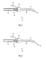
- the in Fig. 1 shown soft tissue laser has a tip 12 which is connected via a connecting body 14 with the soft tissue laser 10 otherwise.
- the soft tissue laser 10 has a light-guiding element 16 which is guided and protected in a guide tube 18.
- the guide tube 18 has at its front end a bead 20 which is intended for the positive coupling to the connecting body 14.
- the connecting body 14 at its end facing the guide tube 18 inwardly facing projections 22 which in Fig. 1 are shown schematically and the spring can engage over the bead 20 and the tip 12 can securely lock on the guide tube 18.
- the tip 12 then has, on the connecting body 14, a shaft 24 which surrounds and protects a second light-guiding element 26.
- the light-guiding element 26 rests flush on an interface 30 and flat against the front end of the light-guiding element 16, so that a coupling efficiency of almost 100% is achieved.
- the planar, mutually facing surfaces of the light-guiding element 16 and of the light-guiding element 26 are aligned exactly with one another, which is supported by the guidance of the light-guiding element 26 in the front end of the guide tube 18.
- the spring action of the projections 26th In addition, symmetrically presses the free end of the light guide 26 on the free end of the light guide 16.
- the shaft 24 of the tip 12 then extends coaxially with the light guide element 16 next to the connecting body 14. In the case of the illustrated tip 12, it is then bent toward its front free end 32, the bending radius corresponding to approximately five times the diameter of the light guide element 16.
- Fig. 1 protrudes the second light guide 26 freely out of the shaft 24, wherein the projection dimension in the illustrated tip corresponds to about three times the diameter of the light guide 26. It is understood that the values mentioned can be adapted to the requirements to a large extent.
- the free end 34 of the second light-guiding element 26 can be protected in any suitable manner, for example via a protective film which encloses it.
- the tip 12 is arbitrarily exchangeable for another tip, in which the diameter of the second light-guiding element 26 is different, in which the projection dimension of the end 34 is different, or in which the Abköpfung or turn or the straight course of the tip is designed differently.
- the tip 12 used is defined by a control device 36, which is shown schematically in the manner of a block diagram in FIG Fig. 1 is shown and which is arranged in the region of the housing of the soft tissue laser 10.
- the controller 36 determines the appropriate tip by itself.
- the light source 38 of the control device 36 is controlled according to the invention so that the power required for the selected working method is available at the free end 34 of the second light-guiding element.
- the tip 12 is preferably displayed on a screen 40 and displayed and possibly additionally detected by a sensor 42.
- the sensor 42 thus detects how the diameter ratio of the diameter of the light-guiding element 26 to the diameter of the light-guiding element 16 is, and controls the light source 38 in a correspondingly suitable manner.
- both the method of operation used and the tip to be used may be displayed in any manner on the screen 40.
- the inserted tip is also preferably displayed visually on the screen, so that here a safe and ergonomic handling of the soft tissue laser is possible.
- the tip 12 and of course each tip used, will have an appropriate identification, for example via an identification code 44, mounted on the connector body 14 or any other suitable location on the tip 12.
- control device 36 has a microphone and can be operated by voice input, for which purpose a loudspeaker is preferably provided which indicates the set parameter combination by voice output, but also offers, for example, the adjustable combinations by voice output.
- Fig. 2 shows a modified tip 12, wherein the soft tissue laser 10 incidentally the soft tissue laser 10 according to Fig. 1 corresponds and need not be discussed further here.
- the tip 12, the light guide 26 is significantly thinner. Its diameter is approximately half the diameter of the light-guiding element 16, so that in the region of the interface 30 a coupling of only 50% of the free surface of the light-guiding element 16 is possible.
- the output at the free end 34 light output therefore corresponds to about 50% of the light output of the free end according to Fig. 1 ,
- the tip 12 according to Fig. 3 differs from the top 12 according to Fig. 2 This tip is therefore even better suited to provide the desired soft tissue laser light output at bottlenecks, with the longer-protruding free end 34 making careful handling desirable.
Landscapes
- Health & Medical Sciences (AREA)
- Surgery (AREA)
- Physics & Mathematics (AREA)
- Life Sciences & Earth Sciences (AREA)
- Engineering & Computer Science (AREA)
- Medical Informatics (AREA)
- Nuclear Medicine, Radiotherapy & Molecular Imaging (AREA)
- Electromagnetism (AREA)
- Optics & Photonics (AREA)
- Biomedical Technology (AREA)
- Heart & Thoracic Surgery (AREA)
- Otolaryngology (AREA)
- Molecular Biology (AREA)
- Animal Behavior & Ethology (AREA)
- General Health & Medical Sciences (AREA)
- Public Health (AREA)
- Veterinary Medicine (AREA)
- Laser Surgery Devices (AREA)
Abstract
Description
- Die Erfindung betrifft einen Weichgewebelaser, gemäß dem Oberbegriff von Anspruch 1.
- Es ist seit längerem bekannt, die Spitzen von Weichgewebelasern lösbar an dem Weichgewebelaser im Übrigen zu befestigen, wobei durch die Austauschbarkeit der Spitzen sich nicht nur Probleme hinsichtlich der Sterilisation vermeiden lassen, sondern auch die Auswahl der Spitze in Anwendung an den mikrochirurgisch gewünschten Anwendungsfall möglich ist. So wird beispielsweise durch die Wahl einer entsprechenden Spitze die Lichtabgabeleistung an dem Lichtabgabeende der Spitze verändert. Ferner lassen sich aber auch besonders tiefliegende Behandlungsstellen erreichen, wenn das vordere Ende abgekröpft und spitz zulaufend ausgebildet ist.
- Spitzen für faseroptische Kabel auszuwählen, ist aber seit längerem bekannt, wozu beispielhaft auf die
US 3,831,017 zu verweisen ist. Auch wenn bei dieser Lösung der Sterilisierungs-Gesichtspunkt nicht im Vordergrund steht, ist doch die Austauschbarkeit der Spitze bekannt geworden, wobei bei dieser Lösung unterschiedliche Kabelaufnahmen für unterschiedliche Konfigurationen zum Einsatz gelangen. - Für die Bereitstellung der erwünschten Wirkungen ist es bei Weichgewebelasern bekannt geworden, die Strahlung mit einer Steuervorrichtung in spezieller Weise bereitzustellen, beispielsweise über gepulste Strahlung mit einer vorgegebenen Leistung und einem bestimmten Spektrum.
- Ferner ist es bereits vorgeschlagen worden, die austauschbaren Spitzen mit einer Codierung zu versehen und/oder die Spitzen farblich unterschiedlich zu kennzeichnen, um die Leistung deutlich zu machen.
- Nachteilig hierbei ist es, dass die Farbgebung und die entsprechende Leistung nicht ohne weiteres auf der Hand liegt, was insbesondere dann relevant ist, wenn der Weichgewebelaser nicht täglich, sondern lediglich von Fall zu Fall eingesetzt wird, so dass dann die entsprechende Leistung und die farbliche Zuordnung je nachgeschlagen werden muss.
- Ein weiteres Problem besteht darin, dass der Bediener sich beim Wechseln der - farblich unterschiedlich gekennzeichneten Spitzen typischerweise darauf verlässt, dass die aus seiner Sicht durch die Farbe bedingt vorgegebene Laserleistung auch abgegeben wird, also weder zu hoch noch zu gering ist, um das Weichgewebe entsprechend dem Wunsch des Bedieners zu behandeln. Andererseits ist es aber wichtig, dass es beispielsweise nicht versehentlich zu Verbrennungen kommt.
- Daher liegt der Erfindung die Aufgabe zugrunde, einen Weichgewebelaser gemäß dem Oberbegriff von Anspruch 1 zu schaffen, der deutlich bedienungssicherer und auch ergonomisch besser handhabbar ist.
- Diese Aufgabe wird erfindungsgemäß durch Anspruch 1 gelöst. Vorteilhafte Weiterbildungen ergeben sich durch die Unteransprüche.
- Erfindungsgemäß ist es vorgesehen, die Steuerung durch den Bediener, beispielsweise am Bildschirm, so vorzusehen, dass die erwünschte Leistung vorab eingestellt wird. Der Bediener erhält dann die für die gewünschte Leistung geeignete Spitze - oder nach seiner Wahl eine Anzahl von Spitzen, die unterschiedliche Austrittsenden aufweisen, jedoch der gleichen Leistungsstufe zuzurechnen sind - und erhält damit ein bedienungssicheres Gerät, das Laserstrahlung zur Behandlung von Weichgewebe abgibt, und zwar in dem Maße und in der Form, also hinsichtlich des Impuls/Pausen-Verhältnisses des abgegebenen Wellenspektrums usw., wie er es eingestellt hat.
- Überraschend lassen sich mit den erfindungsgemäßen Maßnahmen bedienungssicherere Weichgewebelaser bereitstellen, denn die Steuerung stellt erfindungsgemäß auf die dem Arbeitsende benachbart abgegebene Lichtleistung ab, also nicht beispielsweise auf die elektrische Leistung, die zugeführt wird.
- Die erfindungsgemäße Leistungsanpassung kann in beliebiger geeigneter Weise realisiert sein. Beispielsweise kann die abgegebene Lichtleistung gemessen werden, nachdem die betreffende Spitze aufgesteckt ist, und die elektrische Leistung des Lasers hieran angepasst werden. Es ist auch möglich, die Spitzen je mit einer Codierung auszustatten, die die Leistungsreduktion der betreffenden Spitze anzeigt und dadurch eine verlässliche Angabe über die abgegebene Schneidleistung des Weichgewebelasers ermöglicht.
- Erfindungsgemäß besonders günstig ist es, wenn die Vorgabe des Benutzers hinsichtlich der Lichtleistung als vorrangig von der Steuervorrichtung eingestellt ist und auch die aktuell benutzte Spitze berücksichtigt wird. Hierzu kann eine Spitzenerkennung verwendet werden, beispielsweise mit einer entsprechenden Codierung, die die je verwendete Spitze erfasst. Damit ist sichergestellt, dass die abzugebende Lichtleistung den Erwartungen des Benutzers entspricht.
- Wenn beispielsweise die Soll-Leistung, die vom Benutzer eingestellt wird, 2 Watt beträgt und durch die gewählte Spitze die halbe Lichtleistung von dem Lichtleitelement des Lasers zur Spitze übertragen wird, etwa, weil die lichtleitende Fläche der Spitze halb so groß wie die lichtleitende Fläche des Lichtleitelements des Lasers ist, stellt die Steuervorrichtung automatisch eine elektrische Leistung, die der an der Lichtquelle abzugebenden Lichtleistung von 2 Watt entspricht. An dem vorderen Ende der Spitze wird hierdurch eine Lichtleistung von 1 Watt bereitgestellt.
- Besonders günstig ist es, wenn nicht nur die unterschiedlichen Stärken des Spitzen-Lichtleitelements, sondern auch die übrigen Parameter der betreffenden Spitze, also beispielsweise die Spitzenlänge, ggf. die Abkröpfung des vorderen Endes oder beispielsweise die Länge des Lichtleitelements der Spitze, durch eine Codierung deutlich gemacht werden. Die Codierung ist bevorzugt sowohl visuell ersichtlich, beispielsweise über Farb- oder Formgebung eines Haltekörpers des Spitzenelements, aber auch bevorzugt zusätzlich hierzu über eine Codierung, die über einen Sensor erfassbar ist, so dass Informationen über die Art der Spitze der Steuervorrichtung zugeleitet werden können.
- Erfindungsgemäß besonders günstig ist es, dass auf dem Display wenigstens zwei auswählbare Arbeitsverfahren, insbesondere hinsichtlich des zu behandelnden Gewebes, dargestellt sind.
- Erfindungsgemäß besonders günstig ist es, dass für wenigstens ein Arbeitsverfahren ein Incontact-Modus oder ein Noncontact-Modus auswählbar ist.
- Erfindungsgemäß besonders günstig ist es, dass auf dem Display die Form der Spitzen - gerade, schräg oder gebogen - auswählbar ist.
- Erfindungsgemäß besonders günstig ist es, dass in Abhängigkeit von dem gewünschten Arbeitsverfahren von der Steuervorrichtung die zu verwendende Spitze auf dem Display angezeigt und die Leistung der Laserlichtquelle festgelegt wird.
- Erfindungsgemäß besonders günstig ist es, dass die von der Steuervorrichtung festgelegte Leistung der Laserlichtquelle auf dem Display anzeigbar und/oder manuell veränderbar ist.
- Erfindungsgemäß besonders günstig ist es, dass die verschiedenen Spitzen unterschiedliche Identifizierungscodes besitzen und dass der festgelegte Identifizierungscode auf dem Display anzeigbar ist.
- Erfindungsgemäß besonders günstig ist es, dass die Einwegspitzen je einen Identifizierungscode aufweisen, und dass die Aufnahme der Spitzen eine Erfassungsvorrichtung für den Identifizierungscode aufweist, welche Erfassungsvorrichtung der Steuervorrichtung eine Information über die Art der Spitze zuleitet.
- Erfindungsgemäß besonders günstig ist es, dass der Identifizierungscode durch einen Strichcode gebildet ist und dass die Erfassungsvorrichtung einen Strichcode-Lesegerät aufweist.
- Erfindungsgemäß besonders günstig ist es, dass die Erfassungsvorrichtung einen Sensor aufweist, der Vorsprünge und/oder Ausnehmungen an der Spitze erkennt und dass der ldentifizierungscode durch mindestens einen Vorsprung und/oder eine Ausnehmung gebildet ist.
- Erfindungsgemäß besonders günstig ist es, dass eine Durchmesser-Erfassungsvorrichtung der Spitze vorgesehen ist, über welche das Durchmesserverhältnis zwischen dem Durchmesser des Lichtleitelements und dem der Spitze erfassbar ist.
- Erfindungsgemäß besonders günstig ist es, dass die Steuervorrichtung ein Mikrophon aufweist und durch Spracheingabe bedienbar ist.
- Erfindungsgemäß besonders günstig ist es, dass die Steuervorrichtung einen Lautsprecher aufweist und die einstellbare Parameterkombination durch Sprachausgabe angibt.
- Erfindungsgemäß besonders günstig ist es, dass der Identifizierungscode aus Farben besteht und/oder dass das zweite Lichtleitelement der Spitzen einen Durchmesser von 200 µm, 300 µm, 400 µm oder 600 µm haben.
- Erfindungsgemäß besonders günstig ist es, dass das zweite Lichtleitelement 3 mm bis 30 mm über das freie Ende der Spitze herausragt.
- Erfindungsgemäß besonders günstig ist es, dass die Laserlichtquelle eine Leistung von durchschnittlich 6 W bis 12 W besitzt und/oder dass die Laserlichtquelle kontinuierlich und/oder gepulstes Licht erzeugt.
- Erfindungsgemäß besonders günstig ist es, dass im Übergangsbereich beider Lichtleitelemente wenigstens ein optisches Übergangselement angeordnet ist, das den Lichtstrahl des ersten Lichtleitelementes bündelt oder erweitert.
- Weitere Vorteile, Einzelheiten und Merkmale ergeben sich aus der nachfolgenden Beschreibung eines Ausführungsbeispiels anhand der Zeichnungen.
- Es zeigen:
- Fig. 1
- eine schematische Ansicht eines Teils eines erfindungsgemäßen Weichgewebelasers in einer Ausführungsform der Erfindung, unter besonderer Darstellung der Spitze;
- Fig. 2
- die Ausführungsform gemäß
Fig. 1 , wobei eine andere Spitze eingesetzt ist; und - Fig. 3
- die Ausführungsform gemäß
Fig. 1 , wobei eine dritte Spitze eingesetzt ist. - Der in
Fig. 1 dargestellte Weichgewebelaser weist eine Spitze 12 auf, die über einen Verbindungskörper 14 mit dem Weichgewebelaser 10 im Übrigen verbunden ist. Der Weichgewebelaser 10 weist ein Lichtleitelement 16 auf, das in einem Führungsrohr 18 geführt und geschützt ist. Das Führungsrohr 18 weist an seinem vorderen Ende einen Wulst 20 auf, der für die formschlüssige Ankopplung an dem Verbindungskörper 14 bestimmt ist. Hierzu weist der Verbindungskörper 14 an seinem dem Führungsrohr 18 zugewandtem Ende nach innen weisende Vorsprünge 22 auf, die inFig. 1 schematisch dargestellt sind und die federnd den Wulst 20 übergreifen können und die Spitze 12 auf dem Führungsrohr 18 sicher arretieren können. - Es versteht sich, dass eine beliebige andere Art der Ankopplung, beispielsweise auch über einem Bajonettvorschluss, ohne Weiteres möglich ist, ohne den Bereich der Erfindung zu verlassen.
- Die Spitze 12 weist anschließend an den Verbindungskörper 14 einen Schaft 24 auf, der ein zweites Lichtleitelement 26 umgibt und schützt. Das Lichtleitelement 26 liegt an einer Schnittstelle 30 bündig und flächig an dem vorderen Ende des Lichtleitelements 16 an, so dass ein Koppelwirkungsgrad von nahezu 100% gegeben ist. Hierzu sind die planen, einander zugewandten Oberflächen des Lichtleitelements 16 und des Lichtleitelements 26 exakt zueinander ausgerichtet, was durch die Führung des Lichtleitelements 26 im vorderen Ende des Führungsrohrs 18 unterstützt wird. Die Federwirkung der Vorsprünge 26 drückt zudem symmetrisch das freie Ende des Lichtleitelements 26 auf das freie Ende des Lichtleitelements 16.
- Der Schaft 24 der Spitze 12 verläuft anschließend an den Verbindungskörper 14 zunächst koaxial mit dem Lichtleitelement 16. Bei der dargestellten Spitze 12 ist er anschließend hieran zu seinem vorderen freien Ende 32 hin abgebogen, wobei der Biegeradius etwa dem fünffachen Durchmesser des Lichtleitelements 16 entspricht.
- Wie aus
Fig. 1 ersichtlich ist, ragt das zweite Lichtleitelement 26 aus dem Schaft 24 frei heraus, wobei das Vorsprungmaß bei der dargestellten Spitze etwa dem dreifachen Durchmesser des Lichtleitelements 26 entspricht. Es versteht sich, dass die genannten Werte in weiten Bereichen an die Erfordernisse anpassbar sind. - Durch das Vorragen ist eine besonders gute Laserlichtbeaufschlagung auch an schwer zugänglichen und engen Stellen gewährleistet. Es versteht sich, dass das freie Ende 34 des zweiten Lichtleitelements 26 in beliebiger geeigneter Weise geschützt sein kann, beispielsweise über eine Schutzfolie, die es umhüllt.
- Erfindungsgemäß ist die Spitze 12 beliebig gegen eine andere Spitze austauschbar, bei der der Durchmesser des zweiten Lichtleitelements 26 anders ist, bei der das Vorsprungmaß des Endes 34 anders ist, oder bei der die Abköpfung oder Abbiegung oder der gerade Verlauf der Spitze anders gestaltet ist. Erfindungsgemäß wird die verwendete Spitze 12 von einer Steuervorrichtung 36 festgelegt, die schematisch nach der Art eines Blockschaltbilds in
Fig. 1 dargestellt ist und die im Bereich des Gehäuses des Weichgewebelasers 10 angeordnet ist. - Die Steuervorrichtung 36 legt von sich aus die geeignete Spitze fest. Die Lichtquelle 38 der Steuervorrichtung 36 wird erfindungsgemäß so gesteuert, dass die für das gewählte Arbeitsverfahren notwendige Leistung am freien Ende 34 des zweiten Lichtleitelements zur Verfügung steht. Hierzu wird bevorzugt die Spitze 12 auf einem Bildschirm 40 dargestellt und angezeigt und ggf. zusätzlich über einen Sensor 42 erkannt. Der Sensor 42 erfasst also, wie das Durchmesserverhältnis des Durchmessers des Lichtleitelements 26 zum Durchmesser des Lichtleitelements 16 ist und steuert die Lichtquelle 38 in entsprechend geeigneter Weise.
- Es versteht sich, dass sowohl das verwendete Arbeitsverfahren als auch die zu verwendete Spitze in beliebiger Weise auf dem Bildschirm 40 dargestellt werden. Bei Verwendung des Sensors 42 wird bevorzugt auch gleich die eingesetzte Spitze visuell auf dem Bildschirm dargestellt, so dass hier eine bedienungssichere und ergonomische Handhabung des Weichgewebelasers möglich ist.
- Es versteht sich, dass die Spitze 12, und natürlich jede verwendete Spitze eine hierfür geeignete Identifizierung, beispielsweise über einen ldentifizierungscode 44 aufweist, der auf dem Verbindungskörper 14 oder an einer beliebig anderen geeigneten Stelle der Spitze 12 angebracht ist.
- In einer modifizierten, hier nicht dargestellten Ausführungsform, weist die Steuervorrichtung 36 eine Mikrophon auf und ist durch Spracheingabe bedienbar, wobei hierzu bevorzugt auch ein Lautsprecher vorgesehen ist, der die eingestellte Parameterkombination durch Sprachausgabe angibt, aber auch beispielsweise die einstellbaren Kombinationen durch Sprachausgabe anbietet.
-
Fig. 2 zeigt eine modifizierte Spitze 12, wobei der Weichgewebelaser 10 im Übrigen dem Weichgewebelaser 10 gemäßFig. 1 entspricht und hier nicht weiter erörtert werden muss. Bei dieser Ausgestaltung der Spitze 12 ist das Lichtleitelement 26 deutlich dünner. Sein Durchmesser beträgt etwa die Hälfte des Durchmessers des Lichtleitelements 16, so dass im Bereich der Schnittstelle 30 eine Ankopplung von lediglich 50% der freien Fläche des Lichtleitelements 16 möglich ist. Die an dem freien Ende 34 abgegebene Lichtleistung entspricht daher etwa 50% der Lichtleistung des freien Endes gemäßFig. 1 . - Dies ist durch einen entsprechend modifizierten Identifizierungscode 44 deutlich gemacht, so dass über den Sensor 42 automatisch erkannt wird, dass eine andere Spitze 12 eingesetzt ist.
- Die Spitze 12 gemäß
Fig. 3 unterscheidet sich von der Spitze 12 gemäßFig. 2 durch ein länger vorragendes freies Ende 34. Diese Spitze ist im Grunde daher noch besser geeignet, an Engstellen die erwünschte Weichgewebelaserlichtleistung bereitzustellen, wobei durch das länger vorragende freie Ende 34 eine vorsichtige Handhabung wünschenswert ist.
Claims (17)
- Weichgewebelaser mit einem Display, einer Steuervorrichtung, einer steuerbaren Laserlichtquelle, einem ersten Lichtleitelement und einer Aufnahme an einem lichtaustrittseitigen Ende des ersten Lichtleitelements, an dem verschiedene, ein zweites Lichtleitelement aufweisende Spitzen lösbar anordbar sind, die sich im Durchmesser des zweiten Lichtleitelements und/oder in dem Betrag voneinander unterscheiden, um den der zweiten Lichtleiter das freie Ende der Spitze axial überragt, dadurch gekennzeichnet, dass die Steuervorrichtung (36), insbesondere in Abhängigkeit von dem gewünschten Arbeitsverfahren, die geeignete Spitze (12) festlegt und die Laserlichtquelle (38) so steuert, dass die für das gewählte Arbeitsverfahren notwendige Leistung am freien Ende des zweiten Lichtleitelements (26) zur Verfügung steht.
- Weichgewebelaser nach Anspruch 1, dadurch gekennzeichnet, dass auf dem Display wenigstens zwei auswählbare Arbeitsverfahren, insbesondere hinsichtlich des zu behandelnden Gewebes, dargestellt sind.
- Weichgewebelaser nach Anspruch 1 oder 2, dadurch gekennzeichnet, dass für wenigstens ein Arbeitsverfahren ein Incontact-Modus oder ein Noncontact-Modus auswählbar ist.
- Weichgewebelaser nach einem der vorhergehenden Ansprüche, dadurch gekennzeichnet, dass auf dem Display die Form der Spitzen (12) - gerade, schräg oder gebogen - auswählbar ist.
- Weichgewebelaser nach einem der vorhergehenden Ansprüche, dadurch gekennzeichnet, dass in Abhängigkeit von dem gewünschten Arbeitsverfahren von der Steuervorrichtung (36) die zu verwendende Spitze (12) auf dem Display angezeigt und die Leistung der Laserlichtquelle (38) festgelegt wird.
- Weichgewebelaser nach einem der vorhergehenden Ansprüche, dadurch gekennzeichnet, dass die von der Steuervorrichtung (36) festgelegte Leistung der Laserlichtquelle (38) auf dem Display anzeigbar und/oder manuell veränderbar ist.
- Weichgewebelaser nach einem der vorhergehenden Ansprüche, dadurch gekennzeichnet, dass die verschiedenen Spitzen (12) unterschiedliche Identifizierungscodes (44) besitzen und dass der festgelegte ldentifizierungscode (44) auf dem Display anzeigbar ist.
- Weichgewebelaser nach einem der vorhergehenden Ansprüche, dadurch gekennzeichnet, dass die Einwegspitzen je einen ldentifizierungscode (44) aufweisen, und dass die Aufnahme der Spitzen (12) eine Erfassungsvorrichtung (42) für den ldentifizierungscode (44) aufweist, welche Erfassungsvorrichtung der Steuervorrichtung (36) eine Information über die Art der Spitze (12) zuleitet.
- Weichgewebelaser nach Anspruch 6, dadurch gekennzeichnet, dass der ldentifizierungscode (44) durch einen Strichcode gebildet ist und dass die Erfassungsvorrichtung (42) einen Strichcode-Lesegerät aufweist.
- Weichgewebelaser nach Anspruch 6, dadurch gekennzeichnet, dass die Erfassungsvorrichtung einen Sensor (42) aufweist, der Vorsprünge und/oder Ausnehmungen an der Spitze (12) erkennt und dass der ldentifizierungscode (44) durch mindestens einen Vorsprung und/oder eine Ausnehmung gebildet ist.
- Weichgewebelaser nach einem der vorhergehenden Ansprüche, dadurch gekennzeichnet, dass eine Durchmesser-Erfassungsvorrichtung der Spitze (12) vorgesehen ist, über welche das Durchmesserverhältnis zwischen dem Durchmesser des Lichtleitelements (16) und dem der Spitze (12) erfassbar ist.
- Weichgewebelaser nach einem der vorhergehenden Ansprüche, dadurch gekennzeichnet, dass die Steuervorrichtung (36) ein Mikrophon aufweist und durch Spracheingabe bedienbar ist.
- Weichgewebelaser nach einem der vorhergehenden Ansprüche, dadurch gekennzeichnet, dass die Steuervorrichtung (36) einen Lautsprecher aufweist und die einstellbare Parameterkombination durch Sprachausgabe angibt.
- Weichgewebelaser nach einem der vorhergehenden Ansprüche, dadurch gekennzeichnet, dass der Identifizierungscode (44) aus Farben besteht und/oder dass das zweite Lichtleitelement (26) der Spitzen (12) einen Durchmesser von 200 µm, 300 µm, 400 µm oder 600 µm haben.
- Weichgewebelaser nach einem der vorhergehenden Ansprüche, dadurch gekennzeichnet, dass das zweite Lichtleitelement (26) 3 mm bis 30 mm über das freie Ende der Spitze (12) herausragt.
- Weichgewebelaser nach einem der vorhergehenden Ansprüche, dadurch gekennzeichnet, dass die Laserlichtquelle (38) eine Leistung von durchschnittlich 6 W bis 12 W besitzt und/oder dass die Laserlichtquelle (38) kontinuierlich und/oder gepulstes Licht erzeugt.
- Weichgewebelaser nach einem der vorhergehenden Ansprüche, dadurch gekennzeichnet, dass im Übergangsbereich beider Lichtleitelemente (16, 26) wenigstens ein optisches Übergangselement angeordnet ist, das den Lichtstrahl des ersten Lichtleitelementes bündelt oder erweitert.
Priority Applications (3)
| Application Number | Priority Date | Filing Date | Title |
|---|---|---|---|
| EP10157373A EP2368513B1 (de) | 2010-03-23 | 2010-03-23 | Weichgewebelaser |
| US13/048,073 US20110238049A1 (en) | 2010-03-23 | 2011-03-15 | Soft Tissue Laser |
| JP2011065095A JP2011194239A (ja) | 2010-03-23 | 2011-03-23 | 柔軟組織用レーザ |
Applications Claiming Priority (1)
| Application Number | Priority Date | Filing Date | Title |
|---|---|---|---|
| EP10157373A EP2368513B1 (de) | 2010-03-23 | 2010-03-23 | Weichgewebelaser |
Publications (2)
| Publication Number | Publication Date |
|---|---|
| EP2368513A1 true EP2368513A1 (de) | 2011-09-28 |
| EP2368513B1 EP2368513B1 (de) | 2013-02-13 |
Family
ID=42269739
Family Applications (1)
| Application Number | Title | Priority Date | Filing Date |
|---|---|---|---|
| EP10157373A Not-in-force EP2368513B1 (de) | 2010-03-23 | 2010-03-23 | Weichgewebelaser |
Country Status (3)
| Country | Link |
|---|---|
| US (1) | US20110238049A1 (de) |
| EP (1) | EP2368513B1 (de) |
| JP (1) | JP2011194239A (de) |
Cited By (1)
| Publication number | Priority date | Publication date | Assignee | Title |
|---|---|---|---|---|
| EP4112003A1 (de) | 2021-07-01 | 2023-01-04 | Ivoclar Vivadent AG | Dentalgerät mit spracherkennung |
Families Citing this family (1)
| Publication number | Priority date | Publication date | Assignee | Title |
|---|---|---|---|---|
| DE102024126237B3 (de) | 2024-09-12 | 2025-07-17 | Jenoptik Optical Systems Gmbh | Beleuchtungsvorrichtung und Verfahren zum Erzeugen eines Beleuchtungslichts |
Citations (5)
| Publication number | Priority date | Publication date | Assignee | Title |
|---|---|---|---|---|
| US3831017A (en) | 1972-09-05 | 1974-08-20 | Willmark Prod Co | Selector turret for fiber optic cables |
| DE19916162A1 (de) * | 1999-04-11 | 2000-10-26 | Oralia Gmbh | Dentallasersystem |
| DE10009004A1 (de) * | 2000-02-25 | 2001-10-11 | Oralia Dentalprodukte Gmbh | Modularer Laserapplikator |
| DE20304675U1 (de) * | 2002-06-10 | 2003-06-05 | Schäfer, Olaf, 78224 Singen | Medizinische Gerätschaften für Behandlungen im dentalen Bereich mittels eines Lasers |
| US20060064080A1 (en) * | 2004-09-22 | 2006-03-23 | Densen Cao | Laser systems useful in medicine and dentistry |
Family Cites Families (5)
| Publication number | Priority date | Publication date | Assignee | Title |
|---|---|---|---|---|
| JPH08280709A (ja) * | 1995-04-18 | 1996-10-29 | Olympus Optical Co Ltd | 手術用表示装置 |
| US20060095096A1 (en) * | 2004-09-09 | 2006-05-04 | Debenedictis Leonard C | Interchangeable tips for medical laser treatments and methods for using same |
| US7988688B2 (en) * | 2006-09-21 | 2011-08-02 | Lockheed Martin Corporation | Miniature apparatus and method for optical stimulation of nerves and other animal tissue |
| US7815630B2 (en) * | 2007-01-25 | 2010-10-19 | Biolase Technology, Inc. | Target-close electromagnetic energy emitting device |
| JP2009064994A (ja) * | 2007-09-07 | 2009-03-26 | Panasonic Corp | レーザ装置 |
-
2010
- 2010-03-23 EP EP10157373A patent/EP2368513B1/de not_active Not-in-force
-
2011
- 2011-03-15 US US13/048,073 patent/US20110238049A1/en not_active Abandoned
- 2011-03-23 JP JP2011065095A patent/JP2011194239A/ja active Pending
Patent Citations (5)
| Publication number | Priority date | Publication date | Assignee | Title |
|---|---|---|---|---|
| US3831017A (en) | 1972-09-05 | 1974-08-20 | Willmark Prod Co | Selector turret for fiber optic cables |
| DE19916162A1 (de) * | 1999-04-11 | 2000-10-26 | Oralia Gmbh | Dentallasersystem |
| DE10009004A1 (de) * | 2000-02-25 | 2001-10-11 | Oralia Dentalprodukte Gmbh | Modularer Laserapplikator |
| DE20304675U1 (de) * | 2002-06-10 | 2003-06-05 | Schäfer, Olaf, 78224 Singen | Medizinische Gerätschaften für Behandlungen im dentalen Bereich mittels eines Lasers |
| US20060064080A1 (en) * | 2004-09-22 | 2006-03-23 | Densen Cao | Laser systems useful in medicine and dentistry |
Cited By (2)
| Publication number | Priority date | Publication date | Assignee | Title |
|---|---|---|---|---|
| EP4112003A1 (de) | 2021-07-01 | 2023-01-04 | Ivoclar Vivadent AG | Dentalgerät mit spracherkennung |
| EP4112002A1 (de) | 2021-07-01 | 2023-01-04 | Ivoclar Vivadent AG | Dentalgerät mit spracherkennung |
Also Published As
| Publication number | Publication date |
|---|---|
| JP2011194239A (ja) | 2011-10-06 |
| US20110238049A1 (en) | 2011-09-29 |
| EP2368513B1 (de) | 2013-02-13 |
Similar Documents
| Publication | Publication Date | Title |
|---|---|---|
| EP0827719B1 (de) | Medizinisches oder zahnmedizinisches Laserinstrument, insbesondere für Zahn-Wurzelkanalbehandlungen | |
| EP0480275B1 (de) | Kraftgesteuerter Kontaktapplikator für Laserstrahlung | |
| DE3121287C2 (de) | ||
| EP0827803A2 (de) | Laserinstrument | |
| DE3837048A1 (de) | Lasergeraet | |
| DE10225749A1 (de) | Medizinische Gerätschaften für Behandlungen im dentalen Bereich mittels eines Lasers | |
| DE202016009086U1 (de) | Haarschneidevorrichtung | |
| EP1309284A2 (de) | Handstück zur abstrahlung von licht auf eine hautfläche | |
| EP2590003B1 (de) | Vorrichtung zum Einstellen eines Strahlprofils, Laserbearbeitungsmaschine und Verfahren zur Herstellung der Vorrichtung | |
| EP0523506B2 (de) | Handstück zur stomatologischen Applikation von Laserlicht | |
| EP2368513B1 (de) | Weichgewebelaser | |
| DE19533350B4 (de) | Handstück für ein medizinisches oder zahnärztliches Laser-Behandlungsrät | |
| WO2007144124A1 (de) | Handstück für insbesondere medizinische laseranwendungen | |
| DE4012545C2 (de) | Chirurgie-Handgriff mit einer Aufnahme für eine aktive Elektrode | |
| DE102013212562B4 (de) | Schnittlängenanzeigevorrichtung für eine Handwerkzeugmaschine | |
| DE2701229A1 (de) | Zahnaerztliches handstueck | |
| DE102008019790A1 (de) | Medizinisches Handgerät | |
| EP2339981B1 (de) | Laser-handstück sowie verfahren zu seiner herstellung | |
| CH685470A5 (de) | Zahnärztliches Handstück für die Behandlung von Zähnen mit Laserstrahlen. | |
| EP1195176A2 (de) | Dermatologisches Handstück | |
| DE102007013066A1 (de) | Zahnärztliches Laser-Behandlungsinstrument mit Licht-Auskoppelelement | |
| DE102012208581A1 (de) | Eine optische Faser Poliervorrichtung zum Verwenden mit optischen Verbindern von verschiedenen Größen und Arten | |
| DE102007008115A1 (de) | Zahnärztliches Laser-Behandlungsinstrument mit Licht-Auskoppelelement und integrierter Wasserbefeuchtung | |
| DE102010000973B4 (de) | Handwerkzeug mit Projektionselement sowie Projektionselement | |
| DE4432159B4 (de) | Medizinisches oder zahnärztliches Laser-Behandlungsgerät |
Legal Events
| Date | Code | Title | Description |
|---|---|---|---|
| PUAI | Public reference made under article 153(3) epc to a published international application that has entered the european phase |
Free format text: ORIGINAL CODE: 0009012 |
|
| AK | Designated contracting states |
Kind code of ref document: A1 Designated state(s): AT BE BG CH CY CZ DE DK EE ES FI FR GB GR HR HU IE IS IT LI LT LU LV MC MK MT NL NO PL PT RO SE SI SK SM TR |
|
| AX | Request for extension of the european patent |
Extension state: AL BA ME RS |
|
| 17P | Request for examination filed |
Effective date: 20120313 |
|
| RIC1 | Information provided on ipc code assigned before grant |
Ipc: A61B 18/22 20060101AFI20120810BHEP Ipc: A61C 1/00 20060101ALN20120810BHEP Ipc: A61B 19/00 20060101ALN20120810BHEP Ipc: A61B 17/00 20060101ALN20120810BHEP |
|
| GRAP | Despatch of communication of intention to grant a patent |
Free format text: ORIGINAL CODE: EPIDOSNIGR1 |
|
| GRAS | Grant fee paid |
Free format text: ORIGINAL CODE: EPIDOSNIGR3 |
|
| GRAA | (expected) grant |
Free format text: ORIGINAL CODE: 0009210 |
|
| AK | Designated contracting states |
Kind code of ref document: B1 Designated state(s): AT BE BG CH CY CZ DE DK EE ES FI FR GB GR HR HU IE IS IT LI LT LU LV MC MK MT NL NO PL PT RO SE SI SK SM TR |
|
| REG | Reference to a national code |
Ref country code: GB Ref legal event code: FG4D Free format text: NOT ENGLISH |
|
| REG | Reference to a national code |
Ref country code: AT Ref legal event code: REF Ref document number: 596054 Country of ref document: AT Kind code of ref document: T Effective date: 20130215 |
|
| REG | Reference to a national code |
Ref country code: IE Ref legal event code: FG4D Free format text: LANGUAGE OF EP DOCUMENT: GERMAN |
|
| REG | Reference to a national code |
Ref country code: CH Ref legal event code: NV Representative=s name: KELLER AND PARTNER PATENTANWAELTE AG, CH |
|
| REG | Reference to a national code |
Ref country code: DE Ref legal event code: R096 Ref document number: 502010002291 Country of ref document: DE Effective date: 20130411 |
|
| REG | Reference to a national code |
Ref country code: NL Ref legal event code: VDEP Effective date: 20130213 |
|
| REG | Reference to a national code |
Ref country code: LT Ref legal event code: MG4D |
|
| PG25 | Lapsed in a contracting state [announced via postgrant information from national office to epo] |
Ref country code: LT Free format text: LAPSE BECAUSE OF FAILURE TO SUBMIT A TRANSLATION OF THE DESCRIPTION OR TO PAY THE FEE WITHIN THE PRESCRIBED TIME-LIMIT Effective date: 20130213 Ref country code: BG Free format text: LAPSE BECAUSE OF FAILURE TO SUBMIT A TRANSLATION OF THE DESCRIPTION OR TO PAY THE FEE WITHIN THE PRESCRIBED TIME-LIMIT Effective date: 20130513 Ref country code: ES Free format text: LAPSE BECAUSE OF FAILURE TO SUBMIT A TRANSLATION OF THE DESCRIPTION OR TO PAY THE FEE WITHIN THE PRESCRIBED TIME-LIMIT Effective date: 20130524 Ref country code: NO Free format text: LAPSE BECAUSE OF FAILURE TO SUBMIT A TRANSLATION OF THE DESCRIPTION OR TO PAY THE FEE WITHIN THE PRESCRIBED TIME-LIMIT Effective date: 20130513 Ref country code: SE Free format text: LAPSE BECAUSE OF FAILURE TO SUBMIT A TRANSLATION OF THE DESCRIPTION OR TO PAY THE FEE WITHIN THE PRESCRIBED TIME-LIMIT Effective date: 20130213 Ref country code: IS Free format text: LAPSE BECAUSE OF FAILURE TO SUBMIT A TRANSLATION OF THE DESCRIPTION OR TO PAY THE FEE WITHIN THE PRESCRIBED TIME-LIMIT Effective date: 20130613 |
|
| PG25 | Lapsed in a contracting state [announced via postgrant information from national office to epo] |
Ref country code: FI Free format text: LAPSE BECAUSE OF FAILURE TO SUBMIT A TRANSLATION OF THE DESCRIPTION OR TO PAY THE FEE WITHIN THE PRESCRIBED TIME-LIMIT Effective date: 20130213 Ref country code: SI Free format text: LAPSE BECAUSE OF FAILURE TO SUBMIT A TRANSLATION OF THE DESCRIPTION OR TO PAY THE FEE WITHIN THE PRESCRIBED TIME-LIMIT Effective date: 20130213 Ref country code: PT Free format text: LAPSE BECAUSE OF FAILURE TO SUBMIT A TRANSLATION OF THE DESCRIPTION OR TO PAY THE FEE WITHIN THE PRESCRIBED TIME-LIMIT Effective date: 20130613 Ref country code: GR Free format text: LAPSE BECAUSE OF FAILURE TO SUBMIT A TRANSLATION OF THE DESCRIPTION OR TO PAY THE FEE WITHIN THE PRESCRIBED TIME-LIMIT Effective date: 20130514 Ref country code: LV Free format text: LAPSE BECAUSE OF FAILURE TO SUBMIT A TRANSLATION OF THE DESCRIPTION OR TO PAY THE FEE WITHIN THE PRESCRIBED TIME-LIMIT Effective date: 20130213 Ref country code: PL Free format text: LAPSE BECAUSE OF FAILURE TO SUBMIT A TRANSLATION OF THE DESCRIPTION OR TO PAY THE FEE WITHIN THE PRESCRIBED TIME-LIMIT Effective date: 20130213 |
|
| BERE | Be: lapsed |
Owner name: IVOCLAR VIVADENT AG Effective date: 20130331 |
|
| PG25 | Lapsed in a contracting state [announced via postgrant information from national office to epo] |
Ref country code: HR Free format text: LAPSE BECAUSE OF FAILURE TO SUBMIT A TRANSLATION OF THE DESCRIPTION OR TO PAY THE FEE WITHIN THE PRESCRIBED TIME-LIMIT Effective date: 20130213 |
|
| PG25 | Lapsed in a contracting state [announced via postgrant information from national office to epo] |
Ref country code: DK Free format text: LAPSE BECAUSE OF FAILURE TO SUBMIT A TRANSLATION OF THE DESCRIPTION OR TO PAY THE FEE WITHIN THE PRESCRIBED TIME-LIMIT Effective date: 20130213 Ref country code: NL Free format text: LAPSE BECAUSE OF FAILURE TO SUBMIT A TRANSLATION OF THE DESCRIPTION OR TO PAY THE FEE WITHIN THE PRESCRIBED TIME-LIMIT Effective date: 20130213 Ref country code: MC Free format text: LAPSE BECAUSE OF NON-PAYMENT OF DUE FEES Effective date: 20130331 Ref country code: SK Free format text: LAPSE BECAUSE OF FAILURE TO SUBMIT A TRANSLATION OF THE DESCRIPTION OR TO PAY THE FEE WITHIN THE PRESCRIBED TIME-LIMIT Effective date: 20130213 Ref country code: EE Free format text: LAPSE BECAUSE OF FAILURE TO SUBMIT A TRANSLATION OF THE DESCRIPTION OR TO PAY THE FEE WITHIN THE PRESCRIBED TIME-LIMIT Effective date: 20130213 Ref country code: RO Free format text: LAPSE BECAUSE OF FAILURE TO SUBMIT A TRANSLATION OF THE DESCRIPTION OR TO PAY THE FEE WITHIN THE PRESCRIBED TIME-LIMIT Effective date: 20130213 Ref country code: CZ Free format text: LAPSE BECAUSE OF FAILURE TO SUBMIT A TRANSLATION OF THE DESCRIPTION OR TO PAY THE FEE WITHIN THE PRESCRIBED TIME-LIMIT Effective date: 20130213 |
|
| PLBE | No opposition filed within time limit |
Free format text: ORIGINAL CODE: 0009261 |
|
| STAA | Information on the status of an ep patent application or granted ep patent |
Free format text: STATUS: NO OPPOSITION FILED WITHIN TIME LIMIT |
|
| REG | Reference to a national code |
Ref country code: FR Ref legal event code: ST Effective date: 20131129 |
|
| REG | Reference to a national code |
Ref country code: IE Ref legal event code: MM4A |
|
| 26N | No opposition filed |
Effective date: 20131114 |
|
| PG25 | Lapsed in a contracting state [announced via postgrant information from national office to epo] |
Ref country code: BE Free format text: LAPSE BECAUSE OF NON-PAYMENT OF DUE FEES Effective date: 20130331 Ref country code: IE Free format text: LAPSE BECAUSE OF NON-PAYMENT OF DUE FEES Effective date: 20130323 Ref country code: FR Free format text: LAPSE BECAUSE OF NON-PAYMENT OF DUE FEES Effective date: 20130415 |
|
| REG | Reference to a national code |
Ref country code: DE Ref legal event code: R097 Ref document number: 502010002291 Country of ref document: DE Effective date: 20131114 |
|
| PG25 | Lapsed in a contracting state [announced via postgrant information from national office to epo] |
Ref country code: MT Free format text: LAPSE BECAUSE OF FAILURE TO SUBMIT A TRANSLATION OF THE DESCRIPTION OR TO PAY THE FEE WITHIN THE PRESCRIBED TIME-LIMIT Effective date: 20130213 |
|
| GBPC | Gb: european patent ceased through non-payment of renewal fee |
Effective date: 20140323 |
|
| PG25 | Lapsed in a contracting state [announced via postgrant information from national office to epo] |
Ref country code: GB Free format text: LAPSE BECAUSE OF NON-PAYMENT OF DUE FEES Effective date: 20140323 |
|
| REG | Reference to a national code |
Ref country code: CH Ref legal event code: PCAR Free format text: NEW ADDRESS: EIGERSTRASSE 2 POSTFACH, 3000 BERN 14 (CH) |
|
| PGFP | Annual fee paid to national office [announced via postgrant information from national office to epo] |
Ref country code: DE Payment date: 20150324 Year of fee payment: 6 Ref country code: CH Payment date: 20150325 Year of fee payment: 6 |
|
| PG25 | Lapsed in a contracting state [announced via postgrant information from national office to epo] |
Ref country code: SM Free format text: LAPSE BECAUSE OF FAILURE TO SUBMIT A TRANSLATION OF THE DESCRIPTION OR TO PAY THE FEE WITHIN THE PRESCRIBED TIME-LIMIT Effective date: 20130213 |
|
| PG25 | Lapsed in a contracting state [announced via postgrant information from national office to epo] |
Ref country code: TR Free format text: LAPSE BECAUSE OF FAILURE TO SUBMIT A TRANSLATION OF THE DESCRIPTION OR TO PAY THE FEE WITHIN THE PRESCRIBED TIME-LIMIT Effective date: 20130213 Ref country code: CY Free format text: LAPSE BECAUSE OF FAILURE TO SUBMIT A TRANSLATION OF THE DESCRIPTION OR TO PAY THE FEE WITHIN THE PRESCRIBED TIME-LIMIT Effective date: 20130213 |
|
| PG25 | Lapsed in a contracting state [announced via postgrant information from national office to epo] |
Ref country code: HU Free format text: LAPSE BECAUSE OF FAILURE TO SUBMIT A TRANSLATION OF THE DESCRIPTION OR TO PAY THE FEE WITHIN THE PRESCRIBED TIME-LIMIT; INVALID AB INITIO Effective date: 20100323 Ref country code: MK Free format text: LAPSE BECAUSE OF FAILURE TO SUBMIT A TRANSLATION OF THE DESCRIPTION OR TO PAY THE FEE WITHIN THE PRESCRIBED TIME-LIMIT Effective date: 20130213 Ref country code: LU Free format text: LAPSE BECAUSE OF NON-PAYMENT OF DUE FEES Effective date: 20130323 |
|
| PGFP | Annual fee paid to national office [announced via postgrant information from national office to epo] |
Ref country code: IT Payment date: 20150330 Year of fee payment: 6 |
|
| REG | Reference to a national code |
Ref country code: AT Ref legal event code: MM01 Ref document number: 596054 Country of ref document: AT Kind code of ref document: T Effective date: 20150323 |
|
| PG25 | Lapsed in a contracting state [announced via postgrant information from national office to epo] |
Ref country code: AT Free format text: LAPSE BECAUSE OF NON-PAYMENT OF DUE FEES Effective date: 20150323 |
|
| REG | Reference to a national code |
Ref country code: DE Ref legal event code: R119 Ref document number: 502010002291 Country of ref document: DE |
|
| REG | Reference to a national code |
Ref country code: CH Ref legal event code: PL |
|
| PG25 | Lapsed in a contracting state [announced via postgrant information from national office to epo] |
Ref country code: CH Free format text: LAPSE BECAUSE OF NON-PAYMENT OF DUE FEES Effective date: 20160331 Ref country code: LI Free format text: LAPSE BECAUSE OF NON-PAYMENT OF DUE FEES Effective date: 20160331 Ref country code: DE Free format text: LAPSE BECAUSE OF NON-PAYMENT OF DUE FEES Effective date: 20161001 |
|
| PG25 | Lapsed in a contracting state [announced via postgrant information from national office to epo] |
Ref country code: IT Free format text: LAPSE BECAUSE OF NON-PAYMENT OF DUE FEES Effective date: 20160323 |