EP2366965B1 - Solarenergiesystem mit Windfahne - Google Patents
Solarenergiesystem mit Windfahne Download PDFInfo
- Publication number
- EP2366965B1 EP2366965B1 EP11158684.8A EP11158684A EP2366965B1 EP 2366965 B1 EP2366965 B1 EP 2366965B1 EP 11158684 A EP11158684 A EP 11158684A EP 2366965 B1 EP2366965 B1 EP 2366965B1
- Authority
- EP
- European Patent Office
- Prior art keywords
- frame
- solar energy
- energy system
- pedestal
- wind vane
- Prior art date
- Legal status (The legal status is an assumption and is not a legal conclusion. Google has not performed a legal analysis and makes no representation as to the accuracy of the status listed.)
- Active
Links
- NJPPVKZQTLUDBO-UHFFFAOYSA-N novaluron Chemical compound C1=C(Cl)C(OC(F)(F)C(OC(F)(F)F)F)=CC=C1NC(=O)NC(=O)C1=C(F)C=CC=C1F NJPPVKZQTLUDBO-UHFFFAOYSA-N 0.000 claims description 44
- 230000002093 peripheral effect Effects 0.000 claims description 4
- 238000005452 bending Methods 0.000 description 6
- 230000007246 mechanism Effects 0.000 description 5
- 238000000034 method Methods 0.000 description 5
- 230000005484 gravity Effects 0.000 description 2
- 238000012986 modification Methods 0.000 description 2
- 230000004048 modification Effects 0.000 description 2
- 229910000831 Steel Inorganic materials 0.000 description 1
- 229910052782 aluminium Inorganic materials 0.000 description 1
- XAGFODPZIPBFFR-UHFFFAOYSA-N aluminium Chemical compound [Al] XAGFODPZIPBFFR-UHFFFAOYSA-N 0.000 description 1
- 238000004891 communication Methods 0.000 description 1
- 230000008602 contraction Effects 0.000 description 1
- 238000013461 design Methods 0.000 description 1
- 229910052751 metal Inorganic materials 0.000 description 1
- 239000002184 metal Substances 0.000 description 1
- 239000010959 steel Substances 0.000 description 1
- 238000012546 transfer Methods 0.000 description 1
- 238000003466 welding Methods 0.000 description 1
Images


Classifications
-
- F—MECHANICAL ENGINEERING; LIGHTING; HEATING; WEAPONS; BLASTING
- F24—HEATING; RANGES; VENTILATING
- F24S—SOLAR HEAT COLLECTORS; SOLAR HEAT SYSTEMS
- F24S30/00—Arrangements for moving or orienting solar heat collector modules
- F24S30/40—Arrangements for moving or orienting solar heat collector modules for rotary movement
- F24S30/45—Arrangements for moving or orienting solar heat collector modules for rotary movement with two rotation axes
- F24S30/452—Vertical primary axis
-
- F—MECHANICAL ENGINEERING; LIGHTING; HEATING; WEAPONS; BLASTING
- F24—HEATING; RANGES; VENTILATING
- F24S—SOLAR HEAT COLLECTORS; SOLAR HEAT SYSTEMS
- F24S40/00—Safety or protection arrangements of solar heat collectors; Preventing malfunction of solar heat collectors
- F24S40/80—Accommodating differential expansion of solar collector elements
- F24S40/85—Arrangements for protecting solar collectors against adverse weather conditions
-
- Y—GENERAL TAGGING OF NEW TECHNOLOGICAL DEVELOPMENTS; GENERAL TAGGING OF CROSS-SECTIONAL TECHNOLOGIES SPANNING OVER SEVERAL SECTIONS OF THE IPC; TECHNICAL SUBJECTS COVERED BY FORMER USPC CROSS-REFERENCE ART COLLECTIONS [XRACs] AND DIGESTS
- Y02—TECHNOLOGIES OR APPLICATIONS FOR MITIGATION OR ADAPTATION AGAINST CLIMATE CHANGE
- Y02E—REDUCTION OF GREENHOUSE GAS [GHG] EMISSIONS, RELATED TO ENERGY GENERATION, TRANSMISSION OR DISTRIBUTION
- Y02E10/00—Energy generation through renewable energy sources
- Y02E10/40—Solar thermal energy, e.g. solar towers
- Y02E10/47—Mountings or tracking
-
- Y—GENERAL TAGGING OF NEW TECHNOLOGICAL DEVELOPMENTS; GENERAL TAGGING OF CROSS-SECTIONAL TECHNOLOGIES SPANNING OVER SEVERAL SECTIONS OF THE IPC; TECHNICAL SUBJECTS COVERED BY FORMER USPC CROSS-REFERENCE ART COLLECTIONS [XRACs] AND DIGESTS
- Y02—TECHNOLOGIES OR APPLICATIONS FOR MITIGATION OR ADAPTATION AGAINST CLIMATE CHANGE
- Y02E—REDUCTION OF GREENHOUSE GAS [GHG] EMISSIONS, RELATED TO ENERGY GENERATION, TRANSMISSION OR DISTRIBUTION
- Y02E10/00—Energy generation through renewable energy sources
- Y02E10/50—Photovoltaic [PV] energy
Definitions
- This application relates to apparatus, systems and methods for minimizing loads acting on solar energy systems, particularly when such solar energy systems are in a stowed configuration.
- Solar energy systems commonly include a frame that supports various photovoltaic cells, solar concentrators, reflectors, mirrors and/or lenses that are used to generate electrical energy from solar energy.
- the frame may support an array of photovoltaic cells or an array of solar concentrator units. Therefore, solar energy systems typically include a solar tracker that maintains alignment between the frame and the sun as the sun moves across the sky.
- US 5,022,929 discloses a solar collector which is constituted by a roof-shaped structure which serves as a support for front and rear panels, in the form of elongated rectangles having the same dimensions as the faces of the said structure, on which various solar energy collecting means are mounted, and whose top longitudinal edges are hinged to a common rotation axis coinciding with the ridge line of the structure.
- this roof-shaped structure forms an assembly which, by means of appropriate mechanisms, can move about a vertical rotation axis.
- the solar collector is also provided with two different orientation systems:
- WO 88/03635 discloses a solar energy transfer spoiler assembly, comprised of a base for supporting the remaining elements of the assembly, an azimuth and elevation drive mechanism, a moving structure frame, a plurality of energy collecting elements, a first spoiler and a second spoiler.
- the first end of the base is fixedly secured to the ground, and the second end is attached to the azimuth and elevation drive mechanism.
- the drive mechanism is comprised of an azimuth drive motor and gearing, and the elevation drive motor and gearing.
- the moving structure is translatably attached to the azimuth and elevation gears for free gimboling movement by the drive mechanism.
- the moving structure is a rectangular shaped frame having disposed thereon a plurality of energy collecting elements.
- Attached to the leading edge of the moving structure frame is the first spoiler or pair of spoilers if the frame is of the split unit design.
- the leading spoiler is attached across each leading edge of the moving structure frame such that center of the plane upon which the solar collecting elements are mounted substantially bisects the midpoint of the widthwise dimension of the first spoiler.
- Attached to the railing edge of the frame or to each unit of the moving structure frame if split units are used, is the second spoiler.
- the second pair of spoilers may be mounted such that the center of the plane upon which the solar collecting elements are mounted also substantially bisects the midpoint of the widthwise dimension of said second pair of spoilers.
- Pedestal-mounted solar energy systems typically include a frame supported on a pedestal. Therefore, pedestal-mounted solar energy systems can sustain significant gravitational loads and wind loads as they track the sun. In an effort to minimize wind damage, pedestal-mounted solar energy systems are stowed in a horizontal configuration when wind speeds exceed a threshold value, such as 35 mph. Nonetheless, due to turbulence, wind rarely blows parallel with the ground. Therefore, even in the stowed configuration, pedestal-mounted solar energy systems are subject to significant bending moments, thereby requiring larger and more expensive tracker and support structures capable of withstanding wind loads.
- the disclosed solar energy system includes a pedestal defining a longitudinal axis, a frame that is supported by the pedestal and that is rotateable relative to the pedestal about the longitudinal axis, the frame including at least one solar device, and a wind vane operatively connected to the frame to urge the frame relative to the pedestal about the longitudinal axis in response to wind acting on the wind vane.
- the disclosed solar energy system further includes a tracker assembly connected to the pedestal.
- the tracker assembly may include an azimuth drive, wherein the azimuth drive is configured to rotate the frame relative to the pedestal about the longitudinal axis, and the wind vane is connected to the tracker assembly.
- the tracker assembly may include an elevation drive.
- the wind vane may include a major surface that defines a second plane, wherein the first plane is substantially perpendicular to the second plane.
- the frame may include an array of said solar devices.
- the solar device may include at least one of a solar concentrator and a photovoltaic cell.
- the wind vane may include a major surface that defines a plane, and the plane is substantially parallel with said longitudinal axis.
- the solar energy system may be used in a method for reducing wind loads acting on a solar energy system.
- the method includes the steps of (1) providing a solar energy system that includes a pedestal defining a longitudinal axis and a frame that is supported by the pedestal and that is rotateable relative to the pedestal about the longitudinal axis, the frame supporting at least one solar device, and (2) connecting a wind vane to an associated tracker assembly to urge the frame relative to the pedestal about the longitudinal axis in response to wind acting on the wind vane.
- a solar energy system may be modified to include a wind vane such that, in the stowed configuration, the wind vane may advantageously orient the system with respect to the wind direction.
- a solar energy system may include a frame with an aspect ratio greater than 1 (i.e., the frame includes a short edge and a long edge) and the system may be modified to include a wind vane.
- the wind vane may orient the frame such that the wind direction is perpendicular to the long edge and parallel with the short edge, thereby minimizing the bending moments acting on the frame.
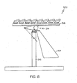
- a solar energy system that does not form part of the invention, generally designated 10, may include a pedestal 12, a tracker assembly 14, a frame 16 and a wind vane 18.
- a controller such as a computer, a microprocessor or like device, may be in communication with the tracker assembly 14 to control actuation of the tracker assembly 14 and, ultimately, the configuration of the frame 16.
- the pedestal 12 may be an elongated, rigid structure, such as a hollow steel post, capable of supporting the mass of the tracker assembly 14 and the frame 16 in a windy outdoor environment.
- the pedestal 12 may define a longitudinal axis A, and may include a first end 20 and a second end 22.
- the first end 20 of the pedestal 12 may be connected to a support structure 24.
- the pedestal 12 may be imbedded in the ground.
- the second end 22 of the pedestal 12 may be connected to the tracker assembly 14.
- the tracker assembly 14 may be any apparatus or system capable of articulating the frame 16 relative to the pedestal 12 about at least one axis.
- the tracker assembly 14 may be actuated to articulate the frame 16 relative to the pedestal 12 to maintain alignment between the frame and the sun as the sun moves across the sky.
- the tracker assembly 14 may be a two-axis tracker and may include an azimuth drive 26 and an elevation drive 28.
- the mounting surface (not shown) may provide structure for connecting the frame 16 to the tracker assembly 14.
- the frame 16 may be connected to the mounting surface using fasteners, such as screws or bolts/nuts, or by welding.
- fasteners such as screws or bolts/nuts, or by welding.
- the azimuth drive 26 may facilitate rotation of the frame 16 relative to the pedestal 12 about the longitudinal axis A of the pedestal 12. Therefore, the azimuth drive 26 may provide the frame 16 with a certain degree (e.g., 180 degrees or 360 degrees) of rotation about the longitudinal axis A relative to the pedestal 12.
- the azimuth drive 26 may include a slew drive that causes rotation about the longitudinal axis A.
- the azimuth drive 26 may be capable of being disengaged (e.g., by way of a clutch or the like) to allow free rotation of the frame 16 relative to the pedestal 12 about the longitudinal axis A of the pedestal 12.
- the elevation drive 28 may facilitate rotation of the frame 16 about a hinge point 32 to facilitate pivoting of the frame 16 relative to the longitudinal axis A of the pedestal 12. Therefore, the elevation drive 28 may control the angle B of the frame 16 relative to the longitudinal axis A of the pedestal 12. While Fig. 1 shows an angle B of 45 degrees and Fig. 2 shows an angle B of 90 degrees, those skilled in the art will appreciate that the elevation drive 28 may be constructed to achieve various angular configurations of the frame 16 relative to the longitudinal axis A of the pedestal 12.
- the elevation drive 28 may include one or more actuators connected to the pedestal 12, wherein extension and contraction of the actuators controls the angle B of the frame 16 relative to the longitudinal axis A of the pedestal 12.
- the azimuth drive 26 and the elevation drive 28 of the tracker assembly 14 may be controlled to position the frame 16 in various configurations, including a stowed configuration.
- the azimuth drive 28 and the elevation drive 28 of the tracker assembly 14 may be capable of stowing the frame 16 in a horizontal configuration (i.e., angle B equals 90 degrees) to minimize wind loads.
- the frame 16 may be any structure that includes at least one solar device 38, whether the solar device 38 is supported by the frame 16 or forms a part of the frame 16.
- the frame 16 may be a solar array and may include an array 40 of solar devices 38.
- solar device whether singular or plural, broadly refers to any apparatus or system used to collect or direct solar energy, particularly for the purpose of generating electrical energy, whether thermally, by photovoltaic process or otherwise.
- the solar devices 38 may be, or may include, photovoltaic cells, solar concentrators, reflectors, mirrors, lenses and combinations thereof.
- the frame 16 may be a generally planar frame that defines an outer peripheral edge 44 and optional upper 42 and lower 43 surfaces.
- the frame 16 may be a generally planar, rectangular frame, wherein the outer peripheral edge 44 includes two opposed long edges 46 and two opposed short edges 48.
- the wind vane 18 may be a relatively thin, rigid, substantially planar structure having a major surface 50 with a relatively high surface area versus cross-sectional thickness.
- the wind vane 18 may be stamped from a sheet of metal, such as aluminum.
- the wind vane 18 may be connected to the underside 43 of the frame 16 such that at least one plane defined by the major surface 50 of the wind vane 18 is substantially parallel with the longitudinal axis A of the pedestal 12.
- the wind vane 18 may be connected to the underside 43 of the frame 16 such that the major surface 50 of the wide vane 18 is substantially perpendicular to the frame 16 or at least one plane defined by the frame 16.
- the surface area of the major surface 50 of the wind vane 18 may be dictated by the amount of force required to rotate the frame 16 relative to the pedestal 12, wherein a greater surface area will provide more rotational force while a smaller surface area will provide less rotational force. Specifically, the surface area of the major surface 50 of the wind vane 18 may be dictated by the amount of force required to overcome frictional forces, gravitational loads, aerodynamic moments and the like, and to allow the frame 16 to rotate about the longitudinal axis A relative to the pedestal 12. However, those skilled in the art will appreciate that the surface area of the wind vane 18 should not be so large that unnecessary forces are placed on the tracker assembly 14 during normal operation.
- the major surface 50 of the wind vane 18 may be positioned to orient the frame 16 as desired relative to the direction of the wind (arrow C).
- the wind vane 18 may be connected to the frame 16 to orient the frame 16 such that the wind (arrow C) is parallel with the short edges 48 of the frame 16 and perpendicular to the long edges 46 of the frame 16, thereby significantly reducing bending moments.
- the shape of the wind vane 18 may be dictated by many factors.
- the wind vane 18 may be shaped such that the center of gravity 52 of the wind vane 18 is positioned at a desired location to minimize bending moments by moving the center of gravity of the whole array 40 as close as possible to the hinge point 32.
- the wind vane 18 may also function as a counterweight.
- an additional counterweight 54 may be connected to the frame 16 or the tracker assembly 14 to counter the weight of the wind vane 18.
- multiple wind vanes may be used.
- system 10 may be modified to include two or more wind vanes 18, wherein the wind vanes 18 are substantially parallel with each other.
- wind vane 18 may be connected to the frame 16 at a hinge (not shown) or the like, thereby allowing the wind vane 18 to selectively move from the deployed configuration shown in Figs. 1 and 2 (i.e., perpendicular to the frame 16) to a stowed configuration (not shown) wherein the wind vane 18 is parallel with the frame 16 (e.g., folded against the frame 16).
- the disclosed solar energy system 10 may be used to minimize wind loads.
- the system 10 may operated in an ordinary fashion when wind speeds are below a threshold value.
- the tracker assembly 14 may move the frame 16 to the stowed configuration (e.g., as shown in Fig. 2 ).
- the azimuth drive 26 may be disengaged, thereby allowing the wind (arrow C in Fig. 2 ) acting on the wind vane 18 to advantageously orient the frame 16.
- the azimuth drive 26 may be reengaged, thereby fixing the position of the frame 16 relative to the wind.
- the azimuth drive 26 may remain disengaged, thereby allowing the frame 16 to oscillate in the wind.
- a first aspect of the disclosed solar energy system according to the invention includes a pedestal 212, a tracker assembly 214, a frame 216 and a wind vane 218.
- Solar energy system 200 may be substantially the same as system 10. However, in system 200, the wind vane 218 may be connected to the tracker assembly 214 as opposed to the frame 216.
- a second aspect of the disclosed solar energy system according to the invention includes a pedestal 312, a tracker assembly 314, a frame 316 and a wind vane 318.
- Solar energy system 300 may be substantially the same as system 200.
- the geometry of the wind vane 318 is such that a greater portion of the surface area of the major surface 350 of the wind vane 318 is closer to the support structure 324 (e.g., the ground) than the frame 316, thereby minimizing the possibility that the wind vane 318 could be shielded by the frame 316 in the un-stowed position.
Landscapes
- Engineering & Computer Science (AREA)
- Physics & Mathematics (AREA)
- Life Sciences & Earth Sciences (AREA)
- Sustainable Development (AREA)
- Sustainable Energy (AREA)
- Thermal Sciences (AREA)
- Chemical & Material Sciences (AREA)
- Combustion & Propulsion (AREA)
- Mechanical Engineering (AREA)
- General Engineering & Computer Science (AREA)
- Wind Motors (AREA)
- Photovoltaic Devices (AREA)
Claims (14)
- Solarenergiesystem (200, 300), das aufweist:einen Ständer (212, 312), der eine Längsachse festlegt;ein Gestell (216, 316), das von dem Ständer getragen wird unddas in Bezug auf den Ständer um die Längsachse schwenkbar ist, wobei das Gestell (216, 316) zumindest eine Solarvorrichtung (38) trägt;eine Nachführeinrichtung (214, 314), die zwischen dem Ständer (212, 312) und dem Gestell (216, 316) angeordnet ist;eine Windfahne (218, 318);wobei das Solarenergiesystem dadurch gekennzeichnet ist, dass die Windfahne mit der Nachführeinrichtung (214, 314) verbunden ist, sodass das Gestell (216, 316) in Folge von auf die Windfahne (218, 318) einwirkendem Wind in Bezug auf den Ständer (212, 312) um die Längsachse getrieben wird.
- Solarenergiesystem nach Anspruch 1, wobei die Nachführeinrichtung (214, 314) einen Azimutantrieb umfasst, der so ausgebildet ist, dass das Gestell (216, 316) in Bezug auf den Ständer (212, 312) um die Längsachse geführt wird.
- Solarenergiesystem nach Anspruch 2, wobei der Azimutantrieb abkoppelbar ist, sodass der Wind das Gestell (216, 316) in Bezug auf den Ständer (212, 312) um die Längsachse drehen kann.
- Solarenergiesystem nach einem der vorhergehenden Ansprüche, wobei die Nachführeinrichtung (214, 314) einen Elevationsantrieb umfasst.
- Solarenergiesystem nach Anspruch 1, wobei es sich bei der Nachführeinrichtung (214, 314) um eine zweiachsige Nachführeinrichtung handelt.
- Solarenergiesystem nach einem der vorhergehenden Ansprüche, wobei die Windfahne (218, 318) eine erste Ebene und das Gestell (216, 316) eine zweite Ebene festlegt und wobei die erste Ebene senkrecht zur zweiten Ebene verläuft.
- Solarenergiesystem nach einem der vorhergehenden Ansprüche, wobei die Windfahne (218, 318) eine Hauptfläche aufweist, die eine Ebene festlegt, und wobei die Ebene parallel zu der Längsachse verläuft.
- Solarenergiesystem nach einem der vorhergehenden Ansprüche, wobei die Windfahne (218, 318) als eine im Wesentlichen flache und planare Struktur ausgebildet ist.
- Solarenergiesystem nach einem der vorhergehenden Ansprüche, wobei die Solarvorrichtung (38) eine Konzentratorsolarzelle und/oder eine Photovoltaikzelle umfasst.
- Solarenergiesystem (200, 300) nach einem der vorhergehenden Ansprüche, das ferner aufweist:eine Stützstruktur (324);wobei der Ständer (212, 312) ein erstes Ende und ein zweites Ende aufweist, wobei das erste Ende des Ständers mit der Stützstruktur verbunden ist und das zweite Ende des Ständers mit der Nachführeinrichtung verbunden ist.
- Solarenergiesystem (300) nach Anspruch 10, wobei die Geometrie der Windfahne (318) so ist, dass ein größerer Teil der Flächenausdehnung einer Hauptfläche (350) der Windfahne (318) näher an der Stützstruktur (324) liegt als an dem Gestell (316).
- Solarenergiesystem (200, 300) nach einem der vorhergehenden Ansprüche, wobei das Gestell (216, 316) eine Solaranordnung ist und ein Array von Solarvorrichtungen (28) umfasst.
- Solarenergiesystem (200, 300) nach einem der vorhergehenden Ansprüche, wobei das Gestell (216, 316) ein allgemein planares rechteckiges Gestell ist, das eine äußere Umfangskante (44) festlegt, wobei die äußere Umfangskante zwei gegenüberliegende lange Kanten (46) und zwei gegenüberliegende kurze Kanten (48) aufweist.
- Solarenergiesystem nach einem der vorhergehenden Ansprüche, wobei die Windfahne einen Schwerpunkt aufweist, der so positioniert ist, dass er ein Gegengewicht für das Solarenergiesystem bildet.
Applications Claiming Priority (1)
| Application Number | Priority Date | Filing Date | Title |
|---|---|---|---|
| US12/726,593 US9175882B2 (en) | 2010-03-18 | 2010-03-18 | Solar energy system with wind vane |
Publications (3)
| Publication Number | Publication Date |
|---|---|
| EP2366965A2 EP2366965A2 (de) | 2011-09-21 |
| EP2366965A3 EP2366965A3 (de) | 2014-07-02 |
| EP2366965B1 true EP2366965B1 (de) | 2015-09-30 |
Family
ID=44168380
Family Applications (1)
| Application Number | Title | Priority Date | Filing Date |
|---|---|---|---|
| EP11158684.8A Active EP2366965B1 (de) | 2010-03-18 | 2011-03-17 | Solarenergiesystem mit Windfahne |
Country Status (4)
| Country | Link |
|---|---|
| US (1) | US9175882B2 (de) |
| EP (1) | EP2366965B1 (de) |
| CN (1) | CN102195524B (de) |
| ES (1) | ES2549586T3 (de) |
Families Citing this family (8)
| Publication number | Priority date | Publication date | Assignee | Title |
|---|---|---|---|---|
| US9203343B2 (en) | 2011-05-26 | 2015-12-01 | Machtwissen.De Ag | Devices for optimizing individual solar modules/collector modules and composite collector module groups and stabilizing the operation thereof against environmental influences, especially wind and particles and objects carried along by the wind |
| DE102011115474A1 (de) * | 2011-10-03 | 2013-04-04 | Machtwissen.De Ag | Vorrichtungen zur Optimierung des Wirkungsgrades, zum Schutz und zur Betriebsstabilisierung solarer Module bei einwirkenden Umwelteinflüssen |
| US9494341B2 (en) | 2011-05-27 | 2016-11-15 | Solarcity Corporation | Solar tracking system employing multiple mobile robots |
| US20130061845A1 (en) * | 2011-09-12 | 2013-03-14 | Zomeworks Corporation | Radiant energy driven orientation system |
| CN104344569A (zh) * | 2013-07-26 | 2015-02-11 | 皇明洁能控股有限公司 | 太阳能灶具 |
| WO2018040113A1 (zh) * | 2016-09-05 | 2018-03-08 | 博立多媒体控股有限公司 | 跟日太阳能系统 |
| US20210071914A1 (en) * | 2019-09-10 | 2021-03-11 | Gamechange Solar Corp. | Self-shielding photovoltaic module tracker apparatus |
| WO2023201264A1 (en) * | 2022-04-12 | 2023-10-19 | Sunfolding, Inc. | Solar module leading edge system and method |
Family Cites Families (25)
| Publication number | Priority date | Publication date | Assignee | Title |
|---|---|---|---|---|
| US2947989A (en) * | 1956-11-28 | 1960-08-02 | Rca Corp | Rotating radar antenna |
| US4108154A (en) | 1976-11-22 | 1978-08-22 | Homer Van Dyke | Solar energy collection system |
| US4204214A (en) | 1978-11-06 | 1980-05-20 | Datron Systems, Inc. | Slewing and tracking mechanism for dish structure |
| JPS55116052A (en) * | 1979-02-27 | 1980-09-06 | Nippon Chem Plant Consultant:Kk | Solar-heat utilizing device |
| US4274394A (en) | 1979-04-17 | 1981-06-23 | The United States Of America As Represented By The United States Department Of Energy | Electromechanical solar tracking apparatus |
| US4343294A (en) | 1979-10-26 | 1982-08-10 | Daniel Jack H | Solar collector assembly |
| WO1983001830A1 (en) | 1981-11-17 | 1983-05-26 | Garrett Michael Sainsbury | Solar collector |
| JPS59212649A (ja) | 1983-05-17 | 1984-12-01 | ガ−レツト マイケル セインスバリ− | 太陽受熱器 |
| US4583520A (en) | 1984-08-01 | 1986-04-22 | Mcdonnell Douglas Corporation | Balanced solar concentrator system |
| US4620771A (en) * | 1984-09-06 | 1986-11-04 | So-Luminaire Systems Corp. | Combined solar tracking reflector and photovoltaic panel |
| JPH02500996A (ja) * | 1986-11-04 | 1990-04-05 | マーチン・マリエッタ・コーポレーション | 改良された太陽光エネルギー追尾装置 |
| US4887589A (en) * | 1987-11-20 | 1989-12-19 | Martin Marietta Corporation | Solar energy tracking structure incorporating wind spoilers |
| FR2643510B1 (fr) | 1989-02-23 | 1994-02-25 | Gallois Montbrun Roger | Capteur solaire perfectionne |
| US5180441A (en) | 1991-06-14 | 1993-01-19 | General Dynamics Corporation/Space Systems Division | Solar concentrator array |
| US5344496A (en) | 1992-11-16 | 1994-09-06 | General Dynamics Corporation, Space Systems Division | Lightweight solar concentrator cell array |
| US5934271A (en) | 1994-07-19 | 1999-08-10 | Anutech Pty Limited | Large aperture solar collectors with improved stability |
| FR2743870B1 (fr) * | 1996-01-24 | 1998-03-20 | Gallois Montbrun Roger | Capteur solaire a dispositif pyramidal orientable |
| US6927695B2 (en) * | 2002-02-12 | 2005-08-09 | Pinnacle West Capital Corporation | Sensor loop with distributed power sources and method therefor |
| CH695707A5 (de) * | 2003-04-07 | 2006-07-31 | Robert Niederer | Versorgungseinheit für Strom und Wasser auf der Basis erneuerbarer Energien. |
| US7252084B2 (en) * | 2004-06-28 | 2007-08-07 | Lucent Technologies Inc. | Solar tracking system |
| US7793654B1 (en) * | 2005-08-11 | 2010-09-14 | Anthony R Thorne | Solar panel positioning apparatus and method |
| ES2288418B1 (es) | 2006-06-19 | 2008-10-16 | Wattpic Energia Intel.Ligent, S.L. | Sistema modular autonomo e interactivo de produccion de energia solar. |
| WO2008112310A1 (en) | 2007-03-14 | 2008-09-18 | Light Prescriptions Innovators, Llc | Optical concentrator, especially for solar photovoltaics |
| US20080308152A1 (en) | 2007-06-15 | 2008-12-18 | The Boeing Company | Solar collector with angled cooling fins |
| US7878191B2 (en) * | 2007-10-31 | 2011-02-01 | Bender William H | Solar collector stabilized by cables and a compression element |
-
2010
- 2010-03-18 US US12/726,593 patent/US9175882B2/en active Active
-
2011
- 2011-03-16 CN CN201110070476.9A patent/CN102195524B/zh active Active
- 2011-03-17 EP EP11158684.8A patent/EP2366965B1/de active Active
- 2011-03-17 ES ES11158684.8T patent/ES2549586T3/es active Active
Also Published As
| Publication number | Publication date |
|---|---|
| US20110226232A1 (en) | 2011-09-22 |
| CN102195524A (zh) | 2011-09-21 |
| EP2366965A3 (de) | 2014-07-02 |
| CN102195524B (zh) | 2016-04-27 |
| US9175882B2 (en) | 2015-11-03 |
| ES2549586T3 (es) | 2015-10-29 |
| EP2366965A2 (de) | 2011-09-21 |
Similar Documents
| Publication | Publication Date | Title |
|---|---|---|
| EP2366965B1 (de) | Solarenergiesystem mit Windfahne | |
| US20100206303A1 (en) | Solar Concentrator Truss Assemblies | |
| US7748376B2 (en) | Solar collector stabilized by cables and a compression element | |
| US8541679B2 (en) | Photo-voltaic power generation equipment that can automatically track the sun | |
| US20130008431A1 (en) | Solar Energy Substrate Aerodynamic Flaps | |
| US9322963B2 (en) | Opposing row linear concentrator architecture | |
| US7923624B2 (en) | Solar concentrator system | |
| US10008977B2 (en) | Heliostat apparatus and solar heat collecting apparatus and concentrating photovoltaic apparatus | |
| US20090107542A1 (en) | Solar collector stabilized by cables and a compression element | |
| US9897346B2 (en) | Opposing row linear concentrator architecture | |
| CN103238033A (zh) | 太阳能收集器系统 | |
| KR100922238B1 (ko) | 태양광 발전장치 | |
| AU2008318598B2 (en) | Solar collector stabilized by cables and a compression element | |
| JP3955958B2 (ja) | 配向可能なピラミッド形太陽集熱器装置 | |
| CN116169943A (zh) | 一种风电和光伏互补发电系统 | |
| US4887589A (en) | Solar energy tracking structure incorporating wind spoilers | |
| CN1010882B (zh) | 改进的太阳能跟踪结构 | |
| US20120132254A1 (en) | Solar tracker device | |
| EP2108900A1 (de) | Sonnennachführeinrichtung | |
| KR20120048761A (ko) | 태양광 추적장치 | |
| Grip | Solar energy system with wind vane | |
| TWM400573U (en) | Sun-tracking frame for solar energy system | |
| CN117478039B (zh) | 一种光伏发电装置 | |
| CN219436926U (zh) | 一种带倾角的单立柱光伏跟踪装置 | |
| WO2021100460A1 (ja) | 太陽光発電装置及び太陽光発電システム |
Legal Events
| Date | Code | Title | Description |
|---|---|---|---|
| PUAI | Public reference made under article 153(3) epc to a published international application that has entered the european phase |
Free format text: ORIGINAL CODE: 0009012 |
|
| 17P | Request for examination filed |
Effective date: 20110317 |
|
| AK | Designated contracting states |
Kind code of ref document: A2 Designated state(s): AL AT BE BG CH CY CZ DE DK EE ES FI FR GB GR HR HU IE IS IT LI LT LU LV MC MK MT NL NO PL PT RO RS SE SI SK SM TR |
|
| AX | Request for extension of the european patent |
Extension state: BA ME |
|
| PUAL | Search report despatched |
Free format text: ORIGINAL CODE: 0009013 |
|
| AK | Designated contracting states |
Kind code of ref document: A3 Designated state(s): AL AT BE BG CH CY CZ DE DK EE ES FI FR GB GR HR HU IE IS IT LI LT LU LV MC MK MT NL NO PL PT RO RS SE SI SK SM TR |
|
| AX | Request for extension of the european patent |
Extension state: BA ME |
|
| RIC1 | Information provided on ipc code assigned before grant |
Ipc: F24J 2/54 20060101AFI20140523BHEP Ipc: F24J 2/46 20060101ALI20140523BHEP |
|
| GRAP | Despatch of communication of intention to grant a patent |
Free format text: ORIGINAL CODE: EPIDOSNIGR1 |
|
| INTG | Intention to grant announced |
Effective date: 20150407 |
|
| GRAS | Grant fee paid |
Free format text: ORIGINAL CODE: EPIDOSNIGR3 |
|
| GRAA | (expected) grant |
Free format text: ORIGINAL CODE: 0009210 |
|
| AK | Designated contracting states |
Kind code of ref document: B1 Designated state(s): AL AT BE BG CH CY CZ DE DK EE ES FI FR GB GR HR HU IE IS IT LI LT LU LV MC MK MT NL NO PL PT RO RS SE SI SK SM TR |
|
| REG | Reference to a national code |
Ref country code: CH Ref legal event code: EP Ref country code: GB Ref legal event code: FG4D |
|
| REG | Reference to a national code |
Ref country code: AT Ref legal event code: REF Ref document number: 752661 Country of ref document: AT Kind code of ref document: T Effective date: 20151015 |
|
| REG | Reference to a national code |
Ref country code: IE Ref legal event code: FG4D |
|
| REG | Reference to a national code |
Ref country code: ES Ref legal event code: FG2A Ref document number: 2549586 Country of ref document: ES Kind code of ref document: T3 Effective date: 20151029 |
|
| REG | Reference to a national code |
Ref country code: DE Ref legal event code: R096 Ref document number: 602011020118 Country of ref document: DE |
|
| PG25 | Lapsed in a contracting state [announced via postgrant information from national office to epo] |
Ref country code: NO Free format text: LAPSE BECAUSE OF FAILURE TO SUBMIT A TRANSLATION OF THE DESCRIPTION OR TO PAY THE FEE WITHIN THE PRESCRIBED TIME-LIMIT Effective date: 20151230 Ref country code: LV Free format text: LAPSE BECAUSE OF FAILURE TO SUBMIT A TRANSLATION OF THE DESCRIPTION OR TO PAY THE FEE WITHIN THE PRESCRIBED TIME-LIMIT Effective date: 20150930 Ref country code: FI Free format text: LAPSE BECAUSE OF FAILURE TO SUBMIT A TRANSLATION OF THE DESCRIPTION OR TO PAY THE FEE WITHIN THE PRESCRIBED TIME-LIMIT Effective date: 20150930 Ref country code: LT Free format text: LAPSE BECAUSE OF FAILURE TO SUBMIT A TRANSLATION OF THE DESCRIPTION OR TO PAY THE FEE WITHIN THE PRESCRIBED TIME-LIMIT Effective date: 20150930 Ref country code: GR Free format text: LAPSE BECAUSE OF FAILURE TO SUBMIT A TRANSLATION OF THE DESCRIPTION OR TO PAY THE FEE WITHIN THE PRESCRIBED TIME-LIMIT Effective date: 20151231 |
|
| REG | Reference to a national code |
Ref country code: NL Ref legal event code: MP Effective date: 20150930 |
|
| REG | Reference to a national code |
Ref country code: LT Ref legal event code: MG4D |
|
| REG | Reference to a national code |
Ref country code: AT Ref legal event code: MK05 Ref document number: 752661 Country of ref document: AT Kind code of ref document: T Effective date: 20150930 |
|
| PG25 | Lapsed in a contracting state [announced via postgrant information from national office to epo] |
Ref country code: SE Free format text: LAPSE BECAUSE OF FAILURE TO SUBMIT A TRANSLATION OF THE DESCRIPTION OR TO PAY THE FEE WITHIN THE PRESCRIBED TIME-LIMIT Effective date: 20150930 Ref country code: HR Free format text: LAPSE BECAUSE OF FAILURE TO SUBMIT A TRANSLATION OF THE DESCRIPTION OR TO PAY THE FEE WITHIN THE PRESCRIBED TIME-LIMIT Effective date: 20150930 Ref country code: RS Free format text: LAPSE BECAUSE OF FAILURE TO SUBMIT A TRANSLATION OF THE DESCRIPTION OR TO PAY THE FEE WITHIN THE PRESCRIBED TIME-LIMIT Effective date: 20150930 |
|
| REG | Reference to a national code |
Ref country code: FR Ref legal event code: PLFP Year of fee payment: 6 |
|
| PG25 | Lapsed in a contracting state [announced via postgrant information from national office to epo] |
Ref country code: IS Free format text: LAPSE BECAUSE OF FAILURE TO SUBMIT A TRANSLATION OF THE DESCRIPTION OR TO PAY THE FEE WITHIN THE PRESCRIBED TIME-LIMIT Effective date: 20160130 Ref country code: SK Free format text: LAPSE BECAUSE OF FAILURE TO SUBMIT A TRANSLATION OF THE DESCRIPTION OR TO PAY THE FEE WITHIN THE PRESCRIBED TIME-LIMIT Effective date: 20150930 Ref country code: NL Free format text: LAPSE BECAUSE OF FAILURE TO SUBMIT A TRANSLATION OF THE DESCRIPTION OR TO PAY THE FEE WITHIN THE PRESCRIBED TIME-LIMIT Effective date: 20150930 Ref country code: CZ Free format text: LAPSE BECAUSE OF FAILURE TO SUBMIT A TRANSLATION OF THE DESCRIPTION OR TO PAY THE FEE WITHIN THE PRESCRIBED TIME-LIMIT Effective date: 20150930 Ref country code: EE Free format text: LAPSE BECAUSE OF FAILURE TO SUBMIT A TRANSLATION OF THE DESCRIPTION OR TO PAY THE FEE WITHIN THE PRESCRIBED TIME-LIMIT Effective date: 20150930 |
|
| PG25 | Lapsed in a contracting state [announced via postgrant information from national office to epo] |
Ref country code: PL Free format text: LAPSE BECAUSE OF FAILURE TO SUBMIT A TRANSLATION OF THE DESCRIPTION OR TO PAY THE FEE WITHIN THE PRESCRIBED TIME-LIMIT Effective date: 20150930 Ref country code: RO Free format text: LAPSE BECAUSE OF FAILURE TO SUBMIT A TRANSLATION OF THE DESCRIPTION OR TO PAY THE FEE WITHIN THE PRESCRIBED TIME-LIMIT Effective date: 20150930 Ref country code: AT Free format text: LAPSE BECAUSE OF FAILURE TO SUBMIT A TRANSLATION OF THE DESCRIPTION OR TO PAY THE FEE WITHIN THE PRESCRIBED TIME-LIMIT Effective date: 20150930 Ref country code: PT Free format text: LAPSE BECAUSE OF FAILURE TO SUBMIT A TRANSLATION OF THE DESCRIPTION OR TO PAY THE FEE WITHIN THE PRESCRIBED TIME-LIMIT Effective date: 20160201 |
|
| REG | Reference to a national code |
Ref country code: DE Ref legal event code: R097 Ref document number: 602011020118 Country of ref document: DE |
|
| PLBE | No opposition filed within time limit |
Free format text: ORIGINAL CODE: 0009261 |
|
| STAA | Information on the status of an ep patent application or granted ep patent |
Free format text: STATUS: NO OPPOSITION FILED WITHIN TIME LIMIT |
|
| PG25 | Lapsed in a contracting state [announced via postgrant information from national office to epo] |
Ref country code: BE Free format text: LAPSE BECAUSE OF NON-PAYMENT OF DUE FEES Effective date: 20160331 Ref country code: DK Free format text: LAPSE BECAUSE OF FAILURE TO SUBMIT A TRANSLATION OF THE DESCRIPTION OR TO PAY THE FEE WITHIN THE PRESCRIBED TIME-LIMIT Effective date: 20150930 |
|
| 26N | No opposition filed |
Effective date: 20160701 |
|
| PG25 | Lapsed in a contracting state [announced via postgrant information from national office to epo] |
Ref country code: LU Free format text: LAPSE BECAUSE OF FAILURE TO SUBMIT A TRANSLATION OF THE DESCRIPTION OR TO PAY THE FEE WITHIN THE PRESCRIBED TIME-LIMIT Effective date: 20160317 Ref country code: MC Free format text: LAPSE BECAUSE OF FAILURE TO SUBMIT A TRANSLATION OF THE DESCRIPTION OR TO PAY THE FEE WITHIN THE PRESCRIBED TIME-LIMIT Effective date: 20150930 |
|
| REG | Reference to a national code |
Ref country code: CH Ref legal event code: PL |
|
| PG25 | Lapsed in a contracting state [announced via postgrant information from national office to epo] |
Ref country code: SI Free format text: LAPSE BECAUSE OF FAILURE TO SUBMIT A TRANSLATION OF THE DESCRIPTION OR TO PAY THE FEE WITHIN THE PRESCRIBED TIME-LIMIT Effective date: 20150930 |
|
| REG | Reference to a national code |
Ref country code: IE Ref legal event code: MM4A |
|
| PG25 | Lapsed in a contracting state [announced via postgrant information from national office to epo] |
Ref country code: BE Free format text: LAPSE BECAUSE OF FAILURE TO SUBMIT A TRANSLATION OF THE DESCRIPTION OR TO PAY THE FEE WITHIN THE PRESCRIBED TIME-LIMIT Effective date: 20150930 |
|
| PG25 | Lapsed in a contracting state [announced via postgrant information from national office to epo] |
Ref country code: CH Free format text: LAPSE BECAUSE OF NON-PAYMENT OF DUE FEES Effective date: 20160331 Ref country code: LI Free format text: LAPSE BECAUSE OF NON-PAYMENT OF DUE FEES Effective date: 20160331 Ref country code: IE Free format text: LAPSE BECAUSE OF NON-PAYMENT OF DUE FEES Effective date: 20160317 |
|
| REG | Reference to a national code |
Ref country code: FR Ref legal event code: PLFP Year of fee payment: 7 |
|
| PG25 | Lapsed in a contracting state [announced via postgrant information from national office to epo] |
Ref country code: MT Free format text: LAPSE BECAUSE OF FAILURE TO SUBMIT A TRANSLATION OF THE DESCRIPTION OR TO PAY THE FEE WITHIN THE PRESCRIBED TIME-LIMIT Effective date: 20150930 |
|
| REG | Reference to a national code |
Ref country code: DE Ref legal event code: R079 Ref document number: 602011020118 Country of ref document: DE Free format text: PREVIOUS MAIN CLASS: F24J0002540000 Ipc: F24S0030400000 |
|
| REG | Reference to a national code |
Ref country code: FR Ref legal event code: PLFP Year of fee payment: 8 |
|
| PG25 | Lapsed in a contracting state [announced via postgrant information from national office to epo] |
Ref country code: CY Free format text: LAPSE BECAUSE OF FAILURE TO SUBMIT A TRANSLATION OF THE DESCRIPTION OR TO PAY THE FEE WITHIN THE PRESCRIBED TIME-LIMIT Effective date: 20150930 Ref country code: HU Free format text: LAPSE BECAUSE OF FAILURE TO SUBMIT A TRANSLATION OF THE DESCRIPTION OR TO PAY THE FEE WITHIN THE PRESCRIBED TIME-LIMIT; INVALID AB INITIO Effective date: 20110317 Ref country code: SM Free format text: LAPSE BECAUSE OF FAILURE TO SUBMIT A TRANSLATION OF THE DESCRIPTION OR TO PAY THE FEE WITHIN THE PRESCRIBED TIME-LIMIT Effective date: 20150930 |
|
| PG25 | Lapsed in a contracting state [announced via postgrant information from national office to epo] |
Ref country code: MT Free format text: LAPSE BECAUSE OF FAILURE TO SUBMIT A TRANSLATION OF THE DESCRIPTION OR TO PAY THE FEE WITHIN THE PRESCRIBED TIME-LIMIT Effective date: 20160331 Ref country code: MK Free format text: LAPSE BECAUSE OF FAILURE TO SUBMIT A TRANSLATION OF THE DESCRIPTION OR TO PAY THE FEE WITHIN THE PRESCRIBED TIME-LIMIT Effective date: 20150930 Ref country code: TR Free format text: LAPSE BECAUSE OF FAILURE TO SUBMIT A TRANSLATION OF THE DESCRIPTION OR TO PAY THE FEE WITHIN THE PRESCRIBED TIME-LIMIT Effective date: 20150930 |
|
| PG25 | Lapsed in a contracting state [announced via postgrant information from national office to epo] |
Ref country code: BG Free format text: LAPSE BECAUSE OF FAILURE TO SUBMIT A TRANSLATION OF THE DESCRIPTION OR TO PAY THE FEE WITHIN THE PRESCRIBED TIME-LIMIT Effective date: 20150930 |
|
| PG25 | Lapsed in a contracting state [announced via postgrant information from national office to epo] |
Ref country code: AL Free format text: LAPSE BECAUSE OF FAILURE TO SUBMIT A TRANSLATION OF THE DESCRIPTION OR TO PAY THE FEE WITHIN THE PRESCRIBED TIME-LIMIT Effective date: 20150930 |
|
| P01 | Opt-out of the competence of the unified patent court (upc) registered |
Effective date: 20230516 |
|
| PGFP | Annual fee paid to national office [announced via postgrant information from national office to epo] |
Ref country code: DE Payment date: 20240327 Year of fee payment: 14 Ref country code: GB Payment date: 20240327 Year of fee payment: 14 |
|
| PGFP | Annual fee paid to national office [announced via postgrant information from national office to epo] |
Ref country code: IT Payment date: 20240321 Year of fee payment: 14 Ref country code: FR Payment date: 20240325 Year of fee payment: 14 |
|
| PGFP | Annual fee paid to national office [announced via postgrant information from national office to epo] |
Ref country code: ES Payment date: 20240401 Year of fee payment: 14 |