EP2366939B1 - Phare de véhicule automobile doté d'une source lumineuse et d'au moins deux éléments optiques répartissant la lumière - Google Patents
Phare de véhicule automobile doté d'une source lumineuse et d'au moins deux éléments optiques répartissant la lumière Download PDFInfo
- Publication number
- EP2366939B1 EP2366939B1 EP11000515.4A EP11000515A EP2366939B1 EP 2366939 B1 EP2366939 B1 EP 2366939B1 EP 11000515 A EP11000515 A EP 11000515A EP 2366939 B1 EP2366939 B1 EP 2366939B1
- Authority
- EP
- European Patent Office
- Prior art keywords
- optical element
- light source
- light
- reflector
- headlamp
- Prior art date
- Legal status (The legal status is an assumption and is not a legal conclusion. Google has not performed a legal analysis and makes no representation as to the accuracy of the status listed.)
- Active
Links
- 230000003287 optical effect Effects 0.000 title claims description 57
- 238000009826 distribution Methods 0.000 claims description 54
- 239000004065 semiconductor Substances 0.000 claims description 37
- 230000003993 interaction Effects 0.000 claims description 6
- 230000005855 radiation Effects 0.000 claims 1
- 230000000694 effects Effects 0.000 description 6
- 238000005286 illumination Methods 0.000 description 5
- 230000008901 benefit Effects 0.000 description 3
- 230000001419 dependent effect Effects 0.000 description 2
- 230000004907 flux Effects 0.000 description 2
- 230000004913 activation Effects 0.000 description 1
- 230000008859 change Effects 0.000 description 1
- 230000001427 coherent effect Effects 0.000 description 1
- 230000000052 comparative effect Effects 0.000 description 1
- 230000006872 improvement Effects 0.000 description 1
- 238000012423 maintenance Methods 0.000 description 1
- 238000004519 manufacturing process Methods 0.000 description 1
- 239000002184 metal Substances 0.000 description 1
- 238000005457 optimization Methods 0.000 description 1
- 229920003023 plastic Polymers 0.000 description 1
- 230000008092 positive effect Effects 0.000 description 1
- 238000004382 potting Methods 0.000 description 1
- 230000035945 sensitivity Effects 0.000 description 1
- 230000007704 transition Effects 0.000 description 1
Images

Classifications
-
- F—MECHANICAL ENGINEERING; LIGHTING; HEATING; WEAPONS; BLASTING
- F21—LIGHTING
- F21S—NON-PORTABLE LIGHTING DEVICES; SYSTEMS THEREOF; VEHICLE LIGHTING DEVICES SPECIALLY ADAPTED FOR VEHICLE EXTERIORS
- F21S41/00—Illuminating devices specially adapted for vehicle exteriors, e.g. headlamps
- F21S41/60—Illuminating devices specially adapted for vehicle exteriors, e.g. headlamps characterised by a variable light distribution
- F21S41/65—Illuminating devices specially adapted for vehicle exteriors, e.g. headlamps characterised by a variable light distribution by acting on light sources
- F21S41/663—Illuminating devices specially adapted for vehicle exteriors, e.g. headlamps characterised by a variable light distribution by acting on light sources by switching light sources
-
- F—MECHANICAL ENGINEERING; LIGHTING; HEATING; WEAPONS; BLASTING
- F21—LIGHTING
- F21S—NON-PORTABLE LIGHTING DEVICES; SYSTEMS THEREOF; VEHICLE LIGHTING DEVICES SPECIALLY ADAPTED FOR VEHICLE EXTERIORS
- F21S41/00—Illuminating devices specially adapted for vehicle exteriors, e.g. headlamps
- F21S41/10—Illuminating devices specially adapted for vehicle exteriors, e.g. headlamps characterised by the light source
- F21S41/14—Illuminating devices specially adapted for vehicle exteriors, e.g. headlamps characterised by the light source characterised by the type of light source
- F21S41/141—Light emitting diodes [LED]
- F21S41/147—Light emitting diodes [LED] the main emission direction of the LED being angled to the optical axis of the illuminating device
- F21S41/148—Light emitting diodes [LED] the main emission direction of the LED being angled to the optical axis of the illuminating device the main emission direction of the LED being perpendicular to the optical axis
-
- F—MECHANICAL ENGINEERING; LIGHTING; HEATING; WEAPONS; BLASTING
- F21—LIGHTING
- F21S—NON-PORTABLE LIGHTING DEVICES; SYSTEMS THEREOF; VEHICLE LIGHTING DEVICES SPECIALLY ADAPTED FOR VEHICLE EXTERIORS
- F21S41/00—Illuminating devices specially adapted for vehicle exteriors, e.g. headlamps
- F21S41/10—Illuminating devices specially adapted for vehicle exteriors, e.g. headlamps characterised by the light source
- F21S41/14—Illuminating devices specially adapted for vehicle exteriors, e.g. headlamps characterised by the light source characterised by the type of light source
- F21S41/141—Light emitting diodes [LED]
- F21S41/151—Light emitting diodes [LED] arranged in one or more lines
-
- F—MECHANICAL ENGINEERING; LIGHTING; HEATING; WEAPONS; BLASTING
- F21—LIGHTING
- F21S—NON-PORTABLE LIGHTING DEVICES; SYSTEMS THEREOF; VEHICLE LIGHTING DEVICES SPECIALLY ADAPTED FOR VEHICLE EXTERIORS
- F21S41/00—Illuminating devices specially adapted for vehicle exteriors, e.g. headlamps
- F21S41/20—Illuminating devices specially adapted for vehicle exteriors, e.g. headlamps characterised by refractors, transparent cover plates, light guides or filters
- F21S41/25—Projection lenses
- F21S41/265—Composite lenses; Lenses with a patch-like shape
-
- F—MECHANICAL ENGINEERING; LIGHTING; HEATING; WEAPONS; BLASTING
- F21—LIGHTING
- F21S—NON-PORTABLE LIGHTING DEVICES; SYSTEMS THEREOF; VEHICLE LIGHTING DEVICES SPECIALLY ADAPTED FOR VEHICLE EXTERIORS
- F21S41/00—Illuminating devices specially adapted for vehicle exteriors, e.g. headlamps
- F21S41/30—Illuminating devices specially adapted for vehicle exteriors, e.g. headlamps characterised by reflectors
- F21S41/32—Optical layout thereof
- F21S41/33—Multi-surface reflectors, e.g. reflectors with facets or reflectors with portions of different curvature
- F21S41/334—Multi-surface reflectors, e.g. reflectors with facets or reflectors with portions of different curvature the reflector consisting of patch like sectors
- F21S41/336—Multi-surface reflectors, e.g. reflectors with facets or reflectors with portions of different curvature the reflector consisting of patch like sectors with discontinuity at the junction between adjacent areas
-
- F—MECHANICAL ENGINEERING; LIGHTING; HEATING; WEAPONS; BLASTING
- F21—LIGHTING
- F21S—NON-PORTABLE LIGHTING DEVICES; SYSTEMS THEREOF; VEHICLE LIGHTING DEVICES SPECIALLY ADAPTED FOR VEHICLE EXTERIORS
- F21S41/00—Illuminating devices specially adapted for vehicle exteriors, e.g. headlamps
- F21S41/30—Illuminating devices specially adapted for vehicle exteriors, e.g. headlamps characterised by reflectors
- F21S41/32—Optical layout thereof
- F21S41/36—Combinations of two or more separate reflectors
-
- F—MECHANICAL ENGINEERING; LIGHTING; HEATING; WEAPONS; BLASTING
- F21—LIGHTING
- F21W—INDEXING SCHEME ASSOCIATED WITH SUBCLASSES F21K, F21L, F21S and F21V, RELATING TO USES OR APPLICATIONS OF LIGHTING DEVICES OR SYSTEMS
- F21W2102/00—Exterior vehicle lighting devices for illuminating purposes
- F21W2102/10—Arrangement or contour of the emitted light
- F21W2102/17—Arrangement or contour of the emitted light for regions other than high beam or low beam
- F21W2102/19—Arrangement or contour of the emitted light for regions other than high beam or low beam for curves
Definitions
- the present invention relates to a motor vehicle headlight with the features of the preamble of claim 1.
- Such a headlight is from the EP 2 028 411 A2 and the EP 1 970 617 A1 known.
- motor vehicle headlights with free-form reflectors are known, the reflection surface of which is subdivided into individual facets or groups of facets and in which different facets or groups of facets are set up to perform different tasks in generating a required total light distribution of the reflector or the headlight.
- An example of such a task is the generation of a first light distribution with a large range, possibly with a light-dark boundary lying relatively far in front of the vehicle.
- Another example is Generation of a second light distribution with a certain light intensity in the lateral apron of the vehicle, which is also referred to as side scatter, and / or in the vicinity of the vehicle.
- the various facets or groups of facets thus represent examples of the optical elements mentioned at the beginning.
- the individual partial areas or facets each have approximately the same focal length and approximately the same distance from the light source.
- the focal length and the distance are primarily based on the requirements for the first light distribution, i.e. the intensity of the light over long ranges, in particular in the vicinity of a light-dark boundary and in the transition from the comparatively bright region below the light-dark boundary to the comparatively dark region above the light-dark boundary .
- comparatively large values of the focal length and the distance between the light source and the optical element are used.
- the object of the invention is to provide a motor vehicle headlamp of the type mentioned at the outset, which allows an improvement in the second light distribution without having to accept unacceptable disadvantages in the first light distribution.
- a first optical element is then arranged at a comparatively large distance from the light source, and a second optical element is in one comparatively small distance from the light source arranged so that a light distribution generated by the first optical element and a light distribution generated by the second optical element overlap.
- a first light distribution generated by the interaction of the first optical element and the light source is comparatively insensitive to the light source geometry.
- a second light distribution generated by the interaction of the second optical element and the light source is comparatively sensitive to the light source geometry.
- Chiaroscuro limits are usually generated with comparatively large focal lengths.
- the fact that the first optical element has a larger focal length than the second optical element allows, in particular, the maintenance of an optimized first light distribution which has a long range and which may have a light-dark boundary.
- the smaller focal length of the second optical element has the advantage that it increases a converging effect of the second optical element, so that the second optical element collects more light than it would collect with a larger focal length.
- the efficiency of the headlamp i.e. the proportion of the luminous flux that produces the desired light distribution, in the total luminous flux of the Light source, enlarged. This enlargement improves in particular the second light distribution and thus in particular the side scatter.
- the light source has a plurality of semiconductor light sources, there is a great deal of design freedom in the design of the light source geometry through a possible variation in the arrangement and the distances of the individual semiconductor light sources, which are only a few mm in size.
- the light source geometry represents an essential influencing variable for the light distribution of the headlamp.
- this embodiment enables a design of the light source geometry that optimizes side scattering is permitted, and any disadvantages that may arise when generating the Patoscuro boundary can be kept within a tolerable range.
- the geometry of the light source can be changed temporarily if necessary, a particular advantage resulting from the fact that the first light distribution is comparatively insensitive to the light source geometry and thus also comparatively insensitive to changes in the light source geometry, while the second light distribution reacts accordingly more strongly to the changes in the light source geometry.
- the clearly perceptible increase in intensity in the vicinity of the vehicle and in front of the vehicle increases safety when turning. This positive effect can be further increased by sequential engagement, the engagement taking place depending on the steering angle, for example.
- the semiconductor light sources are arranged in a row oriented transversely to a main emission direction of the headlights implies different distances of the individual semiconductor light sources from a central axis pointing in the direction of the main emission direction of the headlights, for example an optical axis, the headlights and / or the second optical element.
- the range of the light scattered in the lateral apron improves.
- the individual light sources of the row are arranged relative to a central axis of the second optical element such that a light distribution generated by the second optical element increasingly extends to one side with an increasing number of switched-on light sources.
- An asymmetry of the light source arrangement with respect to the central axis thus leads to a desired asymmetry in the change in the side scatter. This is advantageous if, for example, a right (left) headlight is set up to generate a right (left) cornering light.
- the first optical element is a first reflector region and the second optical element is a second reflector region.
- the invention is not limited to an implementation with reflector areas and can alternatively also be implemented with lenses, the first optical element being a first lens and the second optical element being a second lens.
- the second reflector region has different subregions, each of which is optimized with regard to its interaction with an individually switchable semiconductor light source or individually switchable group of semiconductor light sources, which further improves the side scatter allowed.
- the described configurations of reflector solutions can alternatively be realized by separate reflectors or by different areas of an individual reflector component.
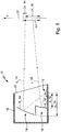
- the shows in detail Fig. 1 a motor vehicle headlight 10 with a light source 12 and at least two optical elements 14, 16, which are arranged together with the light source 12 in the interior of a housing 18 of the headlight 10.
- the otherwise non-transparent housing 18 is covered by a transparent cover 20.
- the optical elements 14, 16 are implemented as reflector regions R_14, R_16.
- the reflector regions R_14, R_16 are set up to distribute light L_14, L_16 of the light source 12 in a predetermined manner.
- a first reflector region R_14 is a first optical element 14 in a comparative manner large distance d_14 to the light source 12, and a second reflector region R_16 is arranged as a second optical element 16 at a comparatively small distance d_16 to the light source 12.
- the light distribution LV predetermined by the shape and arrangement of the reflector regions R_14, R_16, which is established as an illuminated surface on a screen 22 arranged in front of the headlight 10 when the light source 16 is switched on, is composed of a first light distribution LV_14 and a second light distribution LV_16.
- the first light distribution LV_14 is generated by the portion L_14 of the light from the light source 12, which is reflected by the first optical element 14.
- the second light distribution LV_16 is generated by the portion L_16 of the light from the light source 12, which is reflected by the second optical element 16.
- the light distribution LV_14 generated by the first optical element 14 overlaps with the light distribution LV_16 generated by the second optical element 16 to form the light distribution LV, the intensities of the light distributions LV_14, LV_16 adding up in the overlap region.
- the second reflector region R_16 is arranged significantly closer to the light source 12 than the first reflector region R_14, the light distribution LV_16 resulting from the light L_16 of the second reflector region R_16 has a comparatively greater extent in the vertical direction V and is therefore particularly suitable for illuminating the close range in front of the vehicle and to illuminate the side apron.
- the reflector area R_16 also has a comparatively smaller focal length than the first reflector area R_14. He therefore collects comparatively a lot of light and therefore has a comparatively good efficiency, which increases the lighting intensity in the second light distribution LV_16. Due to the comparatively larger focal length of the first reflector region R_14, this allows, for example, a sufficiently sharp light-dark boundary to be generated and / or a comparatively greater concentration of the light at a greater distance in front of the vehicle.
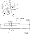
- Fig. 2 shows a perspective view of the arrangement of two reflector regions R_14, R_16 together with a light source 12, as it is with reference to FIG Fig. 1 has been explained, together with details of a preferred embodiment of the light source 12.
- the Fig. 2 a light distribution that results from a specific operating mode of the light source 12.
- the shows in detail Fig. 2 a light source 12 having a plurality of semiconductor light sources 24, 26, 28, 30.
- a majority means any natural number greater than 1.
- the semiconductor light sources 24 to 30 are mounted individually or in groups switchable on a mounting bracket 32.
- the semiconductor light sources 24 to 30 are light-emitting diodes which are activated by control and power electronics in the form of a control unit.
- the control unit can be a component of the headlight 10 or can be arranged as a separate component outside the headlight 10 in the motor vehicle.
- the light from the semiconductor light sources 24 to 30 is preferably only through the reflector, if necessary additionally bundled by an attachment lens or by potting the light source with transparent plastic.
- the mounting bracket 32 can also contain one or more devices for carrying the heat loss that occurs during operation of the semiconductor light sources to a heat sink arranged on the rear of the mounting bracket.
- a mounting bracket 32 with an integrated heat sink, for example in the form of a metal core board, can be used.
- the mounting bracket 32 also serves to fasten the second reflector area R_16, which is arranged comparatively closer to the light source 12 than the first reflector area R_14.
- the mounting bracket 32 is preferably used to assemble the complete reflector component. This achieves an accuracy of the arrangement of the semiconductor light sources 24 to 30 relative to the reflector regions R_14, R_16, which is only limited by the manufacturing accuracy of the mounting bracket 32 and the coherent reflector component.
- FIG. 2 shows an expansion of the light distributions mentioned in the horizontal direction H.
- the light distribution LV_14 for the long range is shown in the qualitative representation of the Fig. 2 on the right side of the Fig. 2 bounded by a vertical straight line G_14 (24).
- the distance between the straight lines G_14 (24) and G_16 (24) represents a measure of the lateral range of the light distribution LV or the light distribution LV_16.
- the semiconductor light sources 24 to 30 are arranged in a row oriented transversely to the main emission direction 34 of the headlight 10. For this reason, the lateral range of the light distribution depends on LV; or the light distribution LV_16 from which of the semiconductor light sources 24 to 26 are switched on.
- the light L_14 and L_16 which generates the light distributions LV_14 and LV_16, is only generated by a single switched on semiconductor light source 24.
- the other semiconductor light sources 26, 28, 30 are switched off.
- the Figure 3 shows the subject of Fig. 2 in a second switch-on state and a resulting, changed light distribution, as well as with the straight lines G_14 (24) and G_16 (24) from the Fig. 2 .
- the straight lines G_14 (24) and G_16 (24) from the Fig. 2 .
- all four semiconductor light sources 24 to 30 are switched on. It can be seen that the light distribution LV_14 has increased comparatively little beyond the position of the straight line G_14 (24) to the right as a result of the switching on of the further light sources 26, 28 and 30.
- the light distribution LV_16 which is generated by the reflector regions R_16 arranged closer to the light source 12, has shifted to the right to a much greater extent beyond the position of the straight line G_16 (24) and is now considered purely qualitatively by the straight line G_16 (24, 26, 28, 30) limited.
- the distance between the straight lines G_16 (24, 26, 28, 30) and G_14 (24), as with the Fig. 2 represents a measure of the lateral range of the light distribution LV or the light distribution LV_16.
- a comparison of this distance in the Fig. 4 with the appropriate distance in the Fig. 2 represents the extent of lateral illumination expansion achieved by the invention. This extent also corresponds directly to the distance of the two straight lines G_16 (24) and G_16 (24, 26, 28, 30) from the Fig. 3 .
- the successive activation takes place as a function of a steering angle of the vehicle in such a way that an increasing steering angle triggers an increase in the range of the lateral illumination. Due to the clear connection effect, for example, a sequential cornering light can be provided in this sense.
- this connection effect also depends on the arrangement of the light sources 24-30 with respect to a central, optical axis of the second reflector region 16.
- a central optical axis corresponds to a beam which is parallel to the main direction of propagation 34 with only one semiconductor light source 24 switched on and which points to the intensity maximum of the resulting second light distribution LV_16.
- the semiconductor light sources 24 to 30 are preferably arranged such that a light distribution LV_16 generated by the second optical element R_16 expands to one side with an increasing number of switched-on light sources.
- Such an effect results in particular for a row arrangement of the semiconductor light sources 24-30 aligned transversely to the central axis, in which the first semiconductor light source 24 lies on the central axis or is closest to the central axis.
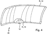
- the Fig. 4 shows an embodiment in which the reflector regions R_14 and R_16 are realized by different regions of an individual reflector component 36.
- the second reflector region 16 protrudes, as it were, with respect to the first reflector region in the direction of the light source 12, so that the second reflector region R_16 lies, as it were, between the first reflector region R_14 and the light source 12.
- the reflector regions R_14 and R_16 can alternatively also be realized by reflectors which are separate from one another, that is to say by separate components, as is shown in FIGS Figures 2 and 3rd suggest.
- the reflector regions R_14 and R_16 are arranged such that the second reflector region R_16 is, as it were, between the first reflector region R_14 and the light source 12.
- the second reflector region R_16 has different subregions, each of which is optimized with regard to its interaction with an individually switchable semiconductor light source or individually switchable group of semiconductor light sources.
- lenses as optical elements 14, 16 or with a lens as optical element 14 and one Reflector as an optical element 16, or with a reflector as an optical element 14 and a lens as an optical element 16 can be achieved.
- a motor vehicle headlight 10 which has the features described here can furthermore have further elements such as further optical elements, light sources and / or light modules.
Landscapes
- Engineering & Computer Science (AREA)
- General Engineering & Computer Science (AREA)
- Physics & Mathematics (AREA)
- Microelectronics & Electronic Packaging (AREA)
- Optics & Photonics (AREA)
- Non-Portable Lighting Devices Or Systems Thereof (AREA)
Claims (7)
- Projecteur de véhicule automobile (10) avec une source de lumière (12) et au moins deux éléments optiques (14, 16), qui sont conçus pour distribuer la lumière de la source de lumière (12) de manière prédéfinie, dans lequel un premier élément optique (14) est disposé à une distance (d_14) relativement importante de la source de lumière (12) et un deuxième élément optique (16) est disposé à une distance (d_16) relativement faible de la source de lumière (12), de sorte qu'une distribution de lumière (LV_14) produite par le premier élément optique (14) et une distribution de lumière (LV_16) produite par le deuxième élément optique (16) se chevauchent, caractérisé en ce que le premier élément optique (14) possède une distance focale plus grande que le deuxième élément optique (16), que la source de lumière (12) présente une pluralité de sources de lumière à semi-conducteur (24, 26, 28, 30), lesquelles sources de lumière à semi-conducteur (24, 26, 28, 30) peuvent être mises en marche individuellement ou par groupes et sont disposées dans une rangée orientée transversalement à une direction d'émission principale (34) du projecteur (10).
- Projecteur (10) selon la revendication 1, caractérisé en ce que les sources de lumière à semi-conducteur (24, 26, 28, 30) individuelles de la rangée sont disposées par rapport à un axe central du deuxième élément optique (16), de sorte qu'une distribution de lumière (LV_16) produite par le deuxième élément optique (16) s'agrandit en augmentant en direction d'un côté à mesure que le nombre de sources de lumière à semi-conducteur (24, 26, 28, 30) mises en marche augmente.
- Projecteur (10) selon l'une quelconque des revendications précédentes, caractérisé en ce que le premier élément optique (14) est une première zone réflectrice (R_14) et que le deuxième élément optique (16) est une deuxième zone réflectrice (R_16).
- Projecteur (10) selon la revendication 3, caractérisé en ce que la deuxième zone réflectrice (R_16) présente différentes zones partielles, dont chacune est optimisée en ce qui concerne sa coopération avec une source de lumière à semi-conducteur (24, 26, 28, 30) pouvant être commutée individuellement ou un groupe pouvant être commuté individuellement de sources de lumière à semi-conducteur (24, 26, 28, 30).
- Projecteur (10) selon la revendication 3 ou 4, caractérisé en ce que les zones réflectrices (R_14, R_16) sont réalisées par des réflecteurs séparés les uns des autres.
- Projecteur (10) selon la revendication 3 ou 4, caractérisé en ce que les zones réflectrices (R_14, R_16) sont réalisées par des zones différentes d'un composant réflecteur (36) individuel.
- Projecteur (10) selon la revendication 1, caractérisé en ce que le premier élément optique (14) est une première lentille et que le deuxième élément optique (16) est une deuxième lentille.
Applications Claiming Priority (1)
| Application Number | Priority Date | Filing Date | Title |
|---|---|---|---|
| DE202010003058U DE202010003058U1 (de) | 2010-03-03 | 2010-03-03 | Kraftfahrzeugscheinwerfer mit einer Lichtquelle und wenigstens zwei Licht verteilenden optischen Elementen |
Publications (3)
| Publication Number | Publication Date |
|---|---|
| EP2366939A2 EP2366939A2 (fr) | 2011-09-21 |
| EP2366939A3 EP2366939A3 (fr) | 2013-10-30 |
| EP2366939B1 true EP2366939B1 (fr) | 2020-06-17 |
Family
ID=42194651
Family Applications (1)
| Application Number | Title | Priority Date | Filing Date |
|---|---|---|---|
| EP11000515.4A Active EP2366939B1 (fr) | 2010-03-03 | 2011-01-22 | Phare de véhicule automobile doté d'une source lumineuse et d'au moins deux éléments optiques répartissant la lumière |
Country Status (3)
| Country | Link |
|---|---|
| EP (1) | EP2366939B1 (fr) |
| CN (1) | CN102192460B (fr) |
| DE (1) | DE202010003058U1 (fr) |
Families Citing this family (14)
| Publication number | Priority date | Publication date | Assignee | Title |
|---|---|---|---|---|
| JP5582865B2 (ja) | 2010-05-12 | 2014-09-03 | 株式会社小糸製作所 | 灯具 |
| DE102010045394A1 (de) * | 2010-09-15 | 2012-03-15 | Osram Opto Semiconductors Gmbh | Leuchte |
| DE102010056311A1 (de) * | 2010-12-27 | 2012-06-28 | Automotive Lighting Reutlingen Gmbh | Beleuchtungseinrichtung eines Kraftfahrzeugs |
| JP5707661B2 (ja) * | 2011-03-25 | 2015-04-30 | スタンレー電気株式会社 | 車両用灯具ユニット及び車両用灯具に用いられる導光体 |
| JP5842435B2 (ja) | 2011-07-26 | 2016-01-13 | 市光工業株式会社 | 車両用前照灯 |
| JP5953665B2 (ja) * | 2011-07-26 | 2016-07-20 | 市光工業株式会社 | 車両用前照灯 |
| DE102011090181B4 (de) * | 2011-12-30 | 2018-02-15 | Automotive Lighting Reutlingen Gmbh | Scheinwerfer für ein Kraftfahrzeug, der eine Teilfernlicht-Lichtverteilung mit Hilfe eines Reflexionssystems erzeugt |
| JP5912539B2 (ja) * | 2012-01-10 | 2016-04-27 | 株式会社小糸製作所 | 車両用前照灯 |
| DE102012202290B4 (de) * | 2012-02-15 | 2014-03-27 | Automotive Lighting Reutlingen Gmbh | Lichtmodul für ein blendungsfreies Kraftfahrzeug-Fernlicht |
| DE102013215359B3 (de) | 2013-08-05 | 2015-02-19 | Automotive Lighting Reutlingen Gmbh | Mechanikfreies Kurvenlichtmodul |
| DE102013220192B4 (de) * | 2013-10-07 | 2015-04-30 | Automotive Lighting Reutlingen Gmbh | LED-Modul eines Kraftfahrzeugscheinwerfers |
| DE102014100727B4 (de) * | 2014-01-23 | 2023-09-21 | HELLA GmbH & Co. KGaA | Verfahren zur Grundeinstellung eines Scheinwerfers |
| DE102017001019A1 (de) * | 2017-02-04 | 2018-08-09 | GM Global Technology Operations LLC (n. d. Ges. d. Staates Delaware) | Fahrzeugscheinwerfer |
| CN109668111A (zh) * | 2019-02-14 | 2019-04-23 | 华域视觉科技(上海)有限公司 | 车用近光灯及包含其的汽车 |
Family Cites Families (7)
| Publication number | Priority date | Publication date | Assignee | Title |
|---|---|---|---|---|
| JP4061251B2 (ja) * | 2003-08-05 | 2008-03-12 | 株式会社小糸製作所 | 車両用灯具 |
| FR2861831B1 (fr) * | 2003-10-31 | 2006-01-20 | Valeo Vision | Module d'eclairage pour projecteur de vehicule |
| JP2008041557A (ja) * | 2006-08-09 | 2008-02-21 | Ichikoh Ind Ltd | 車両用前照灯用の灯具ユニット |
| JP4926771B2 (ja) * | 2007-03-15 | 2012-05-09 | 株式会社小糸製作所 | 車両用灯具ユニット |
| JP4864834B2 (ja) * | 2007-08-21 | 2012-02-01 | 株式会社小糸製作所 | 車両用コーナリングランプ |
| JP4979565B2 (ja) * | 2007-12-14 | 2012-07-18 | 株式会社小糸製作所 | 車両用灯具 |
| EP2322848B1 (fr) * | 2009-11-12 | 2017-09-27 | Stanley Electric Co., Ltd. | Phare de véhicule |
-
2010
- 2010-03-03 DE DE202010003058U patent/DE202010003058U1/de not_active Expired - Lifetime
-
2011
- 2011-01-22 EP EP11000515.4A patent/EP2366939B1/fr active Active
- 2011-03-03 CN CN201110059563.4A patent/CN102192460B/zh not_active Expired - Fee Related
Non-Patent Citations (1)
| Title |
|---|
| None * |
Also Published As
| Publication number | Publication date |
|---|---|
| CN102192460B (zh) | 2015-08-05 |
| DE202010003058U1 (de) | 2010-05-20 |
| EP2366939A2 (fr) | 2011-09-21 |
| CN102192460A (zh) | 2011-09-21 |
| EP2366939A3 (fr) | 2013-10-30 |
Similar Documents
| Publication | Publication Date | Title |
|---|---|---|
| EP2366939B1 (fr) | Phare de véhicule automobile doté d'une source lumineuse et d'au moins deux éléments optiques répartissant la lumière | |
| EP2338732B1 (fr) | Dispositif d'éclairage de véhicule automobile doté d'un guide de lumière et de sources lumineuses de différentes couleurs | |
| EP2823219B1 (fr) | Dispositif d'éclairage pour un véhicule automobile | |
| EP2363320B1 (fr) | Phare frontal doté d'un système de réflexion DEL doté d'une fonction de feux de brouillard et de feux de jour | |
| EP2719940B1 (fr) | Module d'éclairage | |
| EP2339228B1 (fr) | Module d'éclairage pour un dispositif d'éclairage et dispositif d'éclairage d'un véhicule automobile doté d'un tel module d'éclairage | |
| DE102010063713A1 (de) | Beleuchtungsvorrichtung | |
| DE102017219953A1 (de) | Fahrzeugleuchte | |
| EP2431657A2 (fr) | Module de réflecteur d'un phare de véhicule automobile | |
| DE102016201977A1 (de) | Fahrzeugleuchte | |
| DE102011081077A1 (de) | Kraftfahrzeugbeleuchtungseinrichtung | |
| DE102014226881A1 (de) | Kraftfahrzeugscheinwerfer mit einem Zweikammerreflexionssystem | |
| EP2384934A1 (fr) | Lampe de véhicule automobile avec plusieurs fonctions d'éclairage | |
| DE10329185A1 (de) | Leuchte für ein Fahrzeug | |
| DE202017001946U1 (de) | Scheinwerfer mit einem optischen System mit statischem Matrix-Abbiegelicht | |
| EP3176495B1 (fr) | Dispositif d'éclairage de véhicule automobile | |
| DE4224061C2 (de) | Fahrzeugrückleuchte mit Leuchtdiode | |
| DE102006029412B4 (de) | Kraftfahrzeugleuchte | |
| EP2112978B1 (fr) | Phare de véhicule automobile | |
| DE202015009210U1 (de) | Drehbares Beleuchtungs- und/oder Signalisierungsmodul | |
| WO2020126350A1 (fr) | Dispositif d'éclairage pour un phare de véhicule automobile ainsi que phare de véhicule automobile | |
| WO2011012727A1 (fr) | Projecteur dans un véhicule à moteur, comportant une source de lumière semi-conducteur | |
| DE102017222907A1 (de) | Leuchte | |
| EP3812653A1 (fr) | Feu de signalisation pourvu de guide de lumière | |
| EP1126211B1 (fr) | Projecteur de type elliptique pour véhicule automobile |
Legal Events
| Date | Code | Title | Description |
|---|---|---|---|
| PUAI | Public reference made under article 153(3) epc to a published international application that has entered the european phase |
Free format text: ORIGINAL CODE: 0009012 |
|
| AK | Designated contracting states |
Kind code of ref document: A2 Designated state(s): AL AT BE BG CH CY CZ DE DK EE ES FI FR GB GR HR HU IE IS IT LI LT LU LV MC MK MT NL NO PL PT RO RS SE SI SK SM TR |
|
| AX | Request for extension of the european patent |
Extension state: BA ME |
|
| RIN1 | Information on inventor provided before grant (corrected) |
Inventor name: SCHOLL, MICHAEL Inventor name: STADE, FLORIAN |
|
| PUAL | Search report despatched |
Free format text: ORIGINAL CODE: 0009013 |
|
| AK | Designated contracting states |
Kind code of ref document: A3 Designated state(s): AL AT BE BG CH CY CZ DE DK EE ES FI FR GB GR HR HU IE IS IT LI LT LU LV MC MK MT NL NO PL PT RO RS SE SI SK SM TR |
|
| AX | Request for extension of the european patent |
Extension state: BA ME |
|
| RIC1 | Information provided on ipc code assigned before grant |
Ipc: F21S 8/12 20060101AFI20130923BHEP Ipc: F21V 7/00 20060101ALI20130923BHEP Ipc: F21W 101/10 20060101ALN20130923BHEP Ipc: F21S 8/10 20060101ALI20130923BHEP Ipc: F21Y 101/02 20060101ALN20130923BHEP |
|
| 17P | Request for examination filed |
Effective date: 20140429 |
|
| RBV | Designated contracting states (corrected) |
Designated state(s): AL AT BE BG CH CY CZ DE DK EE ES FI FR GB GR HR HU IE IS IT LI LT LU LV MC MK MT NL NO PL PT RO RS SE SI SK SM TR |
|
| REG | Reference to a national code |
Ref country code: DE Ref legal event code: R079 Ref document number: 502011016734 Country of ref document: DE Free format text: PREVIOUS MAIN CLASS: F21S0008120000 Ipc: F21S0041147000 |
|
| RIC1 | Information provided on ipc code assigned before grant |
Ipc: F21S 41/147 20180101AFI20191119BHEP Ipc: F21S 41/663 20180101ALI20191119BHEP Ipc: F21S 41/33 20180101ALI20191119BHEP Ipc: F21S 41/36 20180101ALI20191119BHEP |
|
| GRAP | Despatch of communication of intention to grant a patent |
Free format text: ORIGINAL CODE: EPIDOSNIGR1 |
|
| STAA | Information on the status of an ep patent application or granted ep patent |
Free format text: STATUS: GRANT OF PATENT IS INTENDED |
|
| INTG | Intention to grant announced |
Effective date: 20200110 |
|
| GRAS | Grant fee paid |
Free format text: ORIGINAL CODE: EPIDOSNIGR3 |
|
| GRAA | (expected) grant |
Free format text: ORIGINAL CODE: 0009210 |
|
| STAA | Information on the status of an ep patent application or granted ep patent |
Free format text: STATUS: THE PATENT HAS BEEN GRANTED |
|
| AK | Designated contracting states |
Kind code of ref document: B1 Designated state(s): AL AT BE BG CH CY CZ DE DK EE ES FI FR GB GR HR HU IE IS IT LI LT LU LV MC MK MT NL NO PL PT RO RS SE SI SK SM TR |
|
| REG | Reference to a national code |
Ref country code: GB Ref legal event code: FG4D Free format text: NOT ENGLISH |
|
| REG | Reference to a national code |
Ref country code: CH Ref legal event code: EP |
|
| REG | Reference to a national code |
Ref country code: DE Ref legal event code: R096 Ref document number: 502011016734 Country of ref document: DE |
|
| REG | Reference to a national code |
Ref country code: IE Ref legal event code: FG4D Free format text: LANGUAGE OF EP DOCUMENT: GERMAN |
|
| REG | Reference to a national code |
Ref country code: AT Ref legal event code: REF Ref document number: 1281747 Country of ref document: AT Kind code of ref document: T Effective date: 20200715 |
|
| PG25 | Lapsed in a contracting state [announced via postgrant information from national office to epo] |
Ref country code: LT Free format text: LAPSE BECAUSE OF FAILURE TO SUBMIT A TRANSLATION OF THE DESCRIPTION OR TO PAY THE FEE WITHIN THE PRESCRIBED TIME-LIMIT Effective date: 20200617 Ref country code: NO Free format text: LAPSE BECAUSE OF FAILURE TO SUBMIT A TRANSLATION OF THE DESCRIPTION OR TO PAY THE FEE WITHIN THE PRESCRIBED TIME-LIMIT Effective date: 20200917 Ref country code: SE Free format text: LAPSE BECAUSE OF FAILURE TO SUBMIT A TRANSLATION OF THE DESCRIPTION OR TO PAY THE FEE WITHIN THE PRESCRIBED TIME-LIMIT Effective date: 20200617 Ref country code: GR Free format text: LAPSE BECAUSE OF FAILURE TO SUBMIT A TRANSLATION OF THE DESCRIPTION OR TO PAY THE FEE WITHIN THE PRESCRIBED TIME-LIMIT Effective date: 20200918 Ref country code: FI Free format text: LAPSE BECAUSE OF FAILURE TO SUBMIT A TRANSLATION OF THE DESCRIPTION OR TO PAY THE FEE WITHIN THE PRESCRIBED TIME-LIMIT Effective date: 20200617 |
|
| REG | Reference to a national code |
Ref country code: LT Ref legal event code: MG4D |
|
| REG | Reference to a national code |
Ref country code: DE Ref legal event code: R084 Ref document number: 502011016734 Country of ref document: DE |
|
| REG | Reference to a national code |
Ref country code: NL Ref legal event code: MP Effective date: 20200617 |
|
| PG25 | Lapsed in a contracting state [announced via postgrant information from national office to epo] |
Ref country code: HR Free format text: LAPSE BECAUSE OF FAILURE TO SUBMIT A TRANSLATION OF THE DESCRIPTION OR TO PAY THE FEE WITHIN THE PRESCRIBED TIME-LIMIT Effective date: 20200617 Ref country code: RS Free format text: LAPSE BECAUSE OF FAILURE TO SUBMIT A TRANSLATION OF THE DESCRIPTION OR TO PAY THE FEE WITHIN THE PRESCRIBED TIME-LIMIT Effective date: 20200617 Ref country code: LV Free format text: LAPSE BECAUSE OF FAILURE TO SUBMIT A TRANSLATION OF THE DESCRIPTION OR TO PAY THE FEE WITHIN THE PRESCRIBED TIME-LIMIT Effective date: 20200617 Ref country code: BG Free format text: LAPSE BECAUSE OF FAILURE TO SUBMIT A TRANSLATION OF THE DESCRIPTION OR TO PAY THE FEE WITHIN THE PRESCRIBED TIME-LIMIT Effective date: 20200917 |
|
| PG25 | Lapsed in a contracting state [announced via postgrant information from national office to epo] |
Ref country code: NL Free format text: LAPSE BECAUSE OF FAILURE TO SUBMIT A TRANSLATION OF THE DESCRIPTION OR TO PAY THE FEE WITHIN THE PRESCRIBED TIME-LIMIT Effective date: 20200617 Ref country code: AL Free format text: LAPSE BECAUSE OF FAILURE TO SUBMIT A TRANSLATION OF THE DESCRIPTION OR TO PAY THE FEE WITHIN THE PRESCRIBED TIME-LIMIT Effective date: 20200617 |
|
| PG25 | Lapsed in a contracting state [announced via postgrant information from national office to epo] |
Ref country code: RO Free format text: LAPSE BECAUSE OF FAILURE TO SUBMIT A TRANSLATION OF THE DESCRIPTION OR TO PAY THE FEE WITHIN THE PRESCRIBED TIME-LIMIT Effective date: 20200617 Ref country code: CZ Free format text: LAPSE BECAUSE OF FAILURE TO SUBMIT A TRANSLATION OF THE DESCRIPTION OR TO PAY THE FEE WITHIN THE PRESCRIBED TIME-LIMIT Effective date: 20200617 Ref country code: ES Free format text: LAPSE BECAUSE OF FAILURE TO SUBMIT A TRANSLATION OF THE DESCRIPTION OR TO PAY THE FEE WITHIN THE PRESCRIBED TIME-LIMIT Effective date: 20200617 Ref country code: IT Free format text: LAPSE BECAUSE OF FAILURE TO SUBMIT A TRANSLATION OF THE DESCRIPTION OR TO PAY THE FEE WITHIN THE PRESCRIBED TIME-LIMIT Effective date: 20200617 Ref country code: PT Free format text: LAPSE BECAUSE OF FAILURE TO SUBMIT A TRANSLATION OF THE DESCRIPTION OR TO PAY THE FEE WITHIN THE PRESCRIBED TIME-LIMIT Effective date: 20201019 Ref country code: SM Free format text: LAPSE BECAUSE OF FAILURE TO SUBMIT A TRANSLATION OF THE DESCRIPTION OR TO PAY THE FEE WITHIN THE PRESCRIBED TIME-LIMIT Effective date: 20200617 Ref country code: EE Free format text: LAPSE BECAUSE OF FAILURE TO SUBMIT A TRANSLATION OF THE DESCRIPTION OR TO PAY THE FEE WITHIN THE PRESCRIBED TIME-LIMIT Effective date: 20200617 |
|
| PG25 | Lapsed in a contracting state [announced via postgrant information from national office to epo] |
Ref country code: IS Free format text: LAPSE BECAUSE OF FAILURE TO SUBMIT A TRANSLATION OF THE DESCRIPTION OR TO PAY THE FEE WITHIN THE PRESCRIBED TIME-LIMIT Effective date: 20201017 Ref country code: SK Free format text: LAPSE BECAUSE OF FAILURE TO SUBMIT A TRANSLATION OF THE DESCRIPTION OR TO PAY THE FEE WITHIN THE PRESCRIBED TIME-LIMIT Effective date: 20200617 Ref country code: PL Free format text: LAPSE BECAUSE OF FAILURE TO SUBMIT A TRANSLATION OF THE DESCRIPTION OR TO PAY THE FEE WITHIN THE PRESCRIBED TIME-LIMIT Effective date: 20200617 |
|
| REG | Reference to a national code |
Ref country code: DE Ref legal event code: R026 Ref document number: 502011016734 Country of ref document: DE |
|
| PLBI | Opposition filed |
Free format text: ORIGINAL CODE: 0009260 |
|
| 26 | Opposition filed |
Opponent name: VALEO VISION Effective date: 20210317 |
|
| PG25 | Lapsed in a contracting state [announced via postgrant information from national office to epo] |
Ref country code: DK Free format text: LAPSE BECAUSE OF FAILURE TO SUBMIT A TRANSLATION OF THE DESCRIPTION OR TO PAY THE FEE WITHIN THE PRESCRIBED TIME-LIMIT Effective date: 20200617 |
|
| PG25 | Lapsed in a contracting state [announced via postgrant information from national office to epo] |
Ref country code: SI Free format text: LAPSE BECAUSE OF FAILURE TO SUBMIT A TRANSLATION OF THE DESCRIPTION OR TO PAY THE FEE WITHIN THE PRESCRIBED TIME-LIMIT Effective date: 20200617 |
|
| PLAX | Notice of opposition and request to file observation + time limit sent |
Free format text: ORIGINAL CODE: EPIDOSNOBS2 |
|
| PG25 | Lapsed in a contracting state [announced via postgrant information from national office to epo] |
Ref country code: MC Free format text: LAPSE BECAUSE OF FAILURE TO SUBMIT A TRANSLATION OF THE DESCRIPTION OR TO PAY THE FEE WITHIN THE PRESCRIBED TIME-LIMIT Effective date: 20200617 |
|
| REG | Reference to a national code |
Ref country code: CH Ref legal event code: PL |
|
| GBPC | Gb: european patent ceased through non-payment of renewal fee |
Effective date: 20210122 |
|
| PG25 | Lapsed in a contracting state [announced via postgrant information from national office to epo] |
Ref country code: LU Free format text: LAPSE BECAUSE OF NON-PAYMENT OF DUE FEES Effective date: 20210122 |
|
| REG | Reference to a national code |
Ref country code: BE Ref legal event code: MM Effective date: 20210131 |
|
| PLBB | Reply of patent proprietor to notice(s) of opposition received |
Free format text: ORIGINAL CODE: EPIDOSNOBS3 |
|
| PG25 | Lapsed in a contracting state [announced via postgrant information from national office to epo] |
Ref country code: FR Free format text: LAPSE BECAUSE OF NON-PAYMENT OF DUE FEES Effective date: 20210131 |
|
| PG25 | Lapsed in a contracting state [announced via postgrant information from national office to epo] |
Ref country code: LI Free format text: LAPSE BECAUSE OF NON-PAYMENT OF DUE FEES Effective date: 20210131 Ref country code: CH Free format text: LAPSE BECAUSE OF NON-PAYMENT OF DUE FEES Effective date: 20210131 Ref country code: GB Free format text: LAPSE BECAUSE OF NON-PAYMENT OF DUE FEES Effective date: 20210122 |
|
| PG25 | Lapsed in a contracting state [announced via postgrant information from national office to epo] |
Ref country code: IE Free format text: LAPSE BECAUSE OF NON-PAYMENT OF DUE FEES Effective date: 20210122 |
|
| REG | Reference to a national code |
Ref country code: AT Ref legal event code: MM01 Ref document number: 1281747 Country of ref document: AT Kind code of ref document: T Effective date: 20210122 |
|
| PLBP | Opposition withdrawn |
Free format text: ORIGINAL CODE: 0009264 |
|
| REG | Reference to a national code |
Ref country code: DE Ref legal event code: R100 Ref document number: 502011016734 Country of ref document: DE |
|
| PG25 | Lapsed in a contracting state [announced via postgrant information from national office to epo] |
Ref country code: AT Free format text: LAPSE BECAUSE OF NON-PAYMENT OF DUE FEES Effective date: 20210122 |
|
| PLBD | Termination of opposition procedure: decision despatched |
Free format text: ORIGINAL CODE: EPIDOSNOPC1 |
|
| PG25 | Lapsed in a contracting state [announced via postgrant information from national office to epo] |
Ref country code: IS Free format text: LAPSE BECAUSE OF FAILURE TO SUBMIT A TRANSLATION OF THE DESCRIPTION OR TO PAY THE FEE WITHIN THE PRESCRIBED TIME-LIMIT Effective date: 20201017 |
|
| PLBM | Termination of opposition procedure: date of legal effect published |
Free format text: ORIGINAL CODE: 0009276 |
|
| PG25 | Lapsed in a contracting state [announced via postgrant information from national office to epo] |
Ref country code: BE Free format text: LAPSE BECAUSE OF NON-PAYMENT OF DUE FEES Effective date: 20210131 |
|
| 27C | Opposition proceedings terminated |
Effective date: 20220416 |
|
| PG25 | Lapsed in a contracting state [announced via postgrant information from national office to epo] |
Ref country code: HU Free format text: LAPSE BECAUSE OF FAILURE TO SUBMIT A TRANSLATION OF THE DESCRIPTION OR TO PAY THE FEE WITHIN THE PRESCRIBED TIME-LIMIT; INVALID AB INITIO Effective date: 20110122 Ref country code: CY Free format text: LAPSE BECAUSE OF FAILURE TO SUBMIT A TRANSLATION OF THE DESCRIPTION OR TO PAY THE FEE WITHIN THE PRESCRIBED TIME-LIMIT Effective date: 20200617 |
|
| PG25 | Lapsed in a contracting state [announced via postgrant information from national office to epo] |
Ref country code: MK Free format text: LAPSE BECAUSE OF FAILURE TO SUBMIT A TRANSLATION OF THE DESCRIPTION OR TO PAY THE FEE WITHIN THE PRESCRIBED TIME-LIMIT Effective date: 20200617 |
|
| PGFP | Annual fee paid to national office [announced via postgrant information from national office to epo] |
Ref country code: DE Payment date: 20231219 Year of fee payment: 14 |