EP2366887A1 - Kraftstoffinjektor - Google Patents
Kraftstoffinjektor Download PDFInfo
- Publication number
- EP2366887A1 EP2366887A1 EP11153203A EP11153203A EP2366887A1 EP 2366887 A1 EP2366887 A1 EP 2366887A1 EP 11153203 A EP11153203 A EP 11153203A EP 11153203 A EP11153203 A EP 11153203A EP 2366887 A1 EP2366887 A1 EP 2366887A1
- Authority
- EP
- European Patent Office
- Prior art keywords
- switching valve
- sealing
- fuel injector
- closing element
- sleeve
- Prior art date
- Legal status (The legal status is an assumption and is not a legal conclusion. Google has not performed a legal analysis and makes no representation as to the accuracy of the status listed.)
- Granted
Links
- 239000000446 fuel Substances 0.000 title claims abstract description 43
- 238000007789 sealing Methods 0.000 claims abstract description 84
- 230000006835 compression Effects 0.000 claims abstract description 24
- 238000007906 compression Methods 0.000 claims abstract description 24
- 230000005540 biological transmission Effects 0.000 claims description 14
- 238000013461 design Methods 0.000 description 6
- 238000002347 injection Methods 0.000 description 3
- 239000007924 injection Substances 0.000 description 3
- 238000004519 manufacturing process Methods 0.000 description 3
- 238000005553 drilling Methods 0.000 description 2
- 230000002093 peripheral effect Effects 0.000 description 2
- 230000015572 biosynthetic process Effects 0.000 description 1
- 230000001419 dependent effect Effects 0.000 description 1
- 230000006866 deterioration Effects 0.000 description 1
- 238000011161 development Methods 0.000 description 1
- 230000018109 developmental process Effects 0.000 description 1
- 230000009977 dual effect Effects 0.000 description 1
- 238000000034 method Methods 0.000 description 1
- 238000012856 packing Methods 0.000 description 1
- 238000012549 training Methods 0.000 description 1
Images


Classifications
-
- F—MECHANICAL ENGINEERING; LIGHTING; HEATING; WEAPONS; BLASTING
- F02—COMBUSTION ENGINES; HOT-GAS OR COMBUSTION-PRODUCT ENGINE PLANTS
- F02M—SUPPLYING COMBUSTION ENGINES IN GENERAL WITH COMBUSTIBLE MIXTURES OR CONSTITUENTS THEREOF
- F02M47/00—Fuel-injection apparatus operated cyclically with fuel-injection valves actuated by fluid pressure
- F02M47/02—Fuel-injection apparatus operated cyclically with fuel-injection valves actuated by fluid pressure of accumulator-injector type, i.e. having fuel pressure of accumulator tending to open, and fuel pressure in other chamber tending to close, injection valves and having means for periodically releasing that closing pressure
- F02M47/027—Electrically actuated valves draining the chamber to release the closing pressure
-
- F—MECHANICAL ENGINEERING; LIGHTING; HEATING; WEAPONS; BLASTING
- F02—COMBUSTION ENGINES; HOT-GAS OR COMBUSTION-PRODUCT ENGINE PLANTS
- F02M—SUPPLYING COMBUSTION ENGINES IN GENERAL WITH COMBUSTIBLE MIXTURES OR CONSTITUENTS THEREOF
- F02M63/00—Other fuel-injection apparatus having pertinent characteristics not provided for in groups F02M39/00 - F02M57/00 or F02M67/00; Details, component parts, or accessories of fuel-injection apparatus, not provided for in, or of interest apart from, the apparatus of groups F02M39/00 - F02M61/00 or F02M67/00; Combination of fuel pump with other devices, e.g. lubricating oil pump
- F02M63/0012—Valves
- F02M63/0014—Valves characterised by the valve actuating means
- F02M63/0015—Valves characterised by the valve actuating means electrical, e.g. using solenoid
- F02M63/0026—Valves characterised by the valve actuating means electrical, e.g. using solenoid using piezoelectric or magnetostrictive actuators
-
- F—MECHANICAL ENGINEERING; LIGHTING; HEATING; WEAPONS; BLASTING
- F02—COMBUSTION ENGINES; HOT-GAS OR COMBUSTION-PRODUCT ENGINE PLANTS
- F02M—SUPPLYING COMBUSTION ENGINES IN GENERAL WITH COMBUSTIBLE MIXTURES OR CONSTITUENTS THEREOF
- F02M63/00—Other fuel-injection apparatus having pertinent characteristics not provided for in groups F02M39/00 - F02M57/00 or F02M67/00; Details, component parts, or accessories of fuel-injection apparatus, not provided for in, or of interest apart from, the apparatus of groups F02M39/00 - F02M61/00 or F02M67/00; Combination of fuel pump with other devices, e.g. lubricating oil pump
- F02M63/0012—Valves
- F02M63/0031—Valves characterized by the type of valves, e.g. special valve member details, valve seat details, valve housing details
- F02M63/004—Sliding valves, e.g. spool valves, i.e. whereby the closing member has a sliding movement along a seat for opening and closing
Definitions
- the invention relates to a fuel injector having the features of the preamble of claim 1.
- a fuel injector has a housing part, in which a actuatable by means of a piezoelectric actuator switching valve is received with a liftable closing element.
- the closing element is designed sleeve-shaped for forming a switching valve chamber and for at least partially receiving a stationary sealing body and has a first sealing contour, which cooperates with a formed on the stationary sealing body second sealing contour as a valve seat.
- a generic fuel injector is from the published patent application DE 10 2006 049 831 A1 out.
- the fuel injector described herein has a switching valve and a multi-part piezoelectric actuator for actuating the switching valve.
- the switching valve comprises a sleeve-shaped valve element and a stationary piston, which is accommodated in the valve element. Between the stationary piston and the valve element, a switching valve chamber is formed, which is hydraulically connected via a flow channel and an outlet throttle with a control chamber.
- the drainage channel is passed through the stationary piston and opens via lateral bores in the switching valve space enclosed by the sleeve-shaped valve element.
- a first sealing contour formed on the valve element which cooperates with a second sealing contour formed on the stationary piston, forms a valve seat closing the switching valve chamber.
- the switching valve is designed to be largely pressure balanced by the recorded in the valve element guide diameter of the stationary piston is chosen equal to the diameter in the region of its sealing contour. In the closed position of the switching valve, therefore, substantially only radial forces act on the valve element. This leads to a reduction of the force required to actuate the switching valve, so that the force of the piezoelectric actuator can be reduced.
- the present multipart piezoelectric actuator is arranged such that it or a piezoelectric actuator receiving carrier body surrounds the valve element. As a result, a fuel injector which is compact in the axial direction is created. Furthermore, the known fuel injector is characterized by a small switching valve chamber volume. A small volume ensures a fast increase in pressure in the switching valve chamber and therefore fast switching times.
- fuel injectors with switching valves are also known from the prior art, which are additionally connected via bypass bores or Gudrosseln to a high-pressure supply.
- additional drilling increases the production cost and thus the cost of a fuel injector.
- the present invention is therefore based on the object to improve a fuel injector of the type mentioned above in such a way that it has a minimized switching valve chamber volume in order to further improve the efficiency. Furthermore, a substantially pressure-balanced design of the switching valve should be feasible.
- the Augabe is achieved by a fuel injector having the features of claim 1.
- Advantageous developments of the invention are specified in the dependent claims.
- a sealing sleeve for radially delimiting the switching valve space, which is accommodated at least partially in the sleeve-shaped closing element and axially biased by a compression spring against a throttle plate.
- the sealing sleeve thus ensures the sealing of the switching valve chamber with respect to the throttle plate and the drainage channel formed therein or the outlet throttle formed therein.
- the outflowing fuel passes through the outlet throttle and limited to the throttle plate flow channel directly into the switching valve chamber, so that costly guided by a stationary sealing body bores, which also represent an additional volume to be filled, can be omitted.
- the sealing sleeve accommodated in the sleeve-shaped closing element serves as a filling body, by means of which the volume of the switching valve space is further reduced.
- the sealing sleeve allows a largely pressure-balanced design of the switching valve. Because the sealing sleeve received in the closing element prevents the end faces of the closing element from being acted upon by an axial force in the closed position of the switching valve. By a cylindrical inner contour of the closing element can also be ensured that only radial forces acting on the closing element. In addition, the inner contour of the closing element can deliberately also be designed such that a pressure step is formed in the form of a radially extending shoulder.
- the sealing sleeve is provided for sealing engagement with the throttle plate with a biting edge.
- the biting edge improves due to their annular sealing contour the sealing seat of the sealing sleeve relative to the throttle plate.
- the biting edge is formed in the region of the inner diameter of the sealing sleeve. This has the advantage that the throttle plate facing the end face of the sealing sleeve is not acted upon by high pressure and exerts a compressive force on the sealing sleeve, which counteracts a sealing engagement with the throttle plate.
- the sealing sleeve is to be subjected to a compressive force which acts in the direction of the throttle plate
- the end face opposite the biting edge can be subjected to high pressure and thus used as a pressure stage.
- the training a pressure stage in the form of a radially extending paragraph possible. Due to the additionally acting on the sealing sleeve pressure force in the direction of the throttle plate, accordingly, the spring force of the sealing sleeve bauf profden compression spring can be reduced.
- the sleeve-shaped closing element is axially biased by means of a compression spring against the sealing body.
- the spring force of this compression spring can be reduced if a pressure stage in the form of a radially extending shoulder is formed on the closing element.
- the compression spring is arranged outside of the switching valve chamber in order to keep the volume of the switching valve space as small as possible.
- compression spring may be formed as a helical spring, plate spring or corrugated spring washer.
- the latter require compared to a coil spring a smaller axial space, which in turn allows a reduction of the switching valve chamber volume.
- the piezoelectric actuator for actuating the switching valve via a plate and a plurality of pin-shaped transmission elements with the closing element is operatively connected.
- the bolt-shaped transmission elements are arranged on the plate preferably along a circular line at the same angular distance from each other, wherein the diameter of the circular line is matched to the outer diameter of the closing element, that abut the bolt-shaped transmission elements on an annular end face of the closing element. The force and the stroke of the actuator is thus transmitted via the plate and the transmission elements to the closing element.
- the piezoelectric actuator is arranged outside the housing part and the transmission elements are guided through bores of the housing part, which also serve the hydraulic connection of the switching valve chamber with a return. Due to the dual function provided in the housing part Drilling the design and thus the manufacture of the injector is simplified. The arrangement of the piezoelectric actuator outside of the switching valve receiving housing part simplifies a possibly desired sealing of the actuator relative to the fuel. In addition, the electrical connection of the piezoelectric actuator is facilitated because the leading to the actuator electrical connection cables do not have to be passed through several housing parts.
- the valve seat of the switching valve can be designed as a conical-cone seat or as a ball-and-cone seat.
- the sealing contours formed on the closing element and the sealing body are designed.
- the liftable closing element preferably has an at least partially conical or spherical inner contour for forming the sealing contour.
- the stationary sealing body preferably has an at least partially conical or spherical outer contour for forming the sealing contour.
- the stationary sealing body moreover has a piston-shaped section projecting into the switching valve chamber.
- the piston-shaped gate projecting into the switching valve chamber can cause a significant reduction of the switching valve chamber volume.
- the piston-shaped section thus also serves as a filling body, which limits the switching valve chamber volume to an annular space.
- the stationary sealing body is formed integrally with the switching valve receiving housing part. Due to the one-piece design, the manufacturing or assembly costs can be reduced.
- switching valve 2 comprises a sleeve-shaped closing element 3, which is mounted to a stationary sealing body 5, which is at least partially received in the sleeve-shaped closing element 3, liftable.
- a formed on the closing element 3 first sealing contour 6 cooperates with a second sealing contour 7, which is formed on the stationary sealing body 5.
- the first sealing contour 6 and the second sealing contour 7 thus form a valve seat 8.
- the switching valve 2 further comprises a sealing sleeve 9 which rests sealingly on a throttle plate 11 via a biting edge 12.
- the sealing sleeve 9 is received in the sleeve-shaped closing element 3, so that a switching valve space 4 formed inside the closing element 3 undergoes a reduction.
- a compression spring 10 in the form of a helical spring, the sealing sleeve 9 is axially biased relative to the throttle plate 11.
- the compression spring 10 is for this purpose supported on the one hand on the sealing sleeve 9, on the other hand on the stationary sealing body 5.
- a formed on the sealing sleeve 9 radial shoulder serves the compression spring 10 as a support surface. At the same time, the radial shoulder forms a pressure stage 23 subjected to high pressure, which causes an additional contact force of the sealing sleeve 9 with respect to the throttle plate 11.
- Another compression stage 22 in the form of a radial shoulder is formed on the sleeve-shaped closing element 3.
- the closing element 3 is acted upon in the closing direction with an additional pressure force.
- the spring force of the closing element 3 also acting in the closing direction compression spring 13 may be formed, which is arranged in the present embodiment, the outer peripheral side and on the one hand to a radially extending shoulder of the closing element 3 and on the other hand supported on the throttle plate 11.
- the outer peripheral side arrangement of the compression spring 13 allows a reduction in the diameter of the sealing sleeve 9 and the closing element 3, so that the volume of the switching valve chamber 4 is reduced.
- a piezoelectric actuator 14 arranged in a holding body 19 is provided, which is operatively connected to the closing element 3 of the switching valve 2 via a plate 15 and a plurality of bolt-shaped transmission elements 16 arranged thereon. Due to the arrangement of the piezoelectric actuator 14 in a separate housing part 1 holes 17 are provided in the housing part, through which the bolt-shaped transmission elements 16 can be brought up to the closing element 3.
- the holes 17 are arranged along a circular line at the same angular distance from each other, wherein the diameter of the circular line is matched to the diameter of the sleeve-shaped closing element 3 such that the guided through the holes 17 bolt-shaped transmission elements 16 rest against an annular end face of the closing element 3.
- the inner diameter of the holes 17 are slightly larger than the outer diameter of the bolt-shaped transmission elements 16 selected so that the switching valve chamber 4 via the holes 17 at the same time with a formed in the holding body 19 return 18 is hydraulically connected.
- the housing part 1 also forms the stationary sealing body 5. This means that the stationary sealing body 5 is integrally formed on the housing part 1.
- the operation of the fuel injector is as follows: To open the switching valve 2, the piezoelectric actuator 14 is energized, which expands due to the energization. In this case, the piezoelectric actuator 14 moves the plate 15 including the bolt-shaped transmission elements 16 in the direction of the throttle plate 11th the direct contact of the bolt-shaped transmission elements 16 with the sleeve-shaped closing element 3, this is also moved against the pressure force of the compression spring 13 in the direction of the throttle plate 11, wherein the closing element 3 lifts off from the valve seat 8 and the switching valve 2 opens. Fuel located in the switching valve chamber 4 can now flow, via the sealing contours 6, 7, to the bores 17 and thus to the return 18. About the annular in the region of the valve seat 8 Abström resonance the outflowing fuel or Abgresmenge radially outward of the holes 17 is supplied. Such a flow path has advantages, which will be explained in more detail in connection with a subsequent embodiment.
- the fuel flowing out of the switching valve chamber 4 causes a pressure drop, which likewise sets in a control chamber (not shown) hydraulically connected to the switching valve chamber 4.
- a control chamber (not shown) hydraulically connected to the switching valve chamber 4.
- a flow channel 20 with an outlet throttle 21 is provided in the throttle plate 11.
- the pressure relief in the control chamber allows an opening stroke of a nozzle needle (not shown) through which at least one injection port (not shown) of the fuel injector is released.
- the inventively provided small switching valve volume of the switching valve 2 By the inventively provided small switching valve volume of the switching valve 2, a rapid increase in pressure can be effected with the switching valve 2 closed.
- the fuel injector is characterized by short switching times.
- the control amount is reduced due to the small switching valve volume, which in turn leads to an improvement in the efficiency. Since a faster increase in pressure is guaranteed, additional Bypass bores or filling throttles to shorten the filling time are eliminated. This measure in turn also leads to a reduction in the amount of tax.
- FIG. 2 illustrated embodiment of a fuel injector according to the invention differs from that of FIG. 1 essentially in that the sleeve-shaped closing element 3 has no pressure step 22 formed as radial paragraph.
- the inner contour of the sleeve-shaped closing element 3 is cylindrical up to the sealing contour 6, so that in the closed position of the switching valve 2 the closing element 3 is acted upon by the fuel present in the switching valve space 4 with a pressure force acting only in the radial direction.
- the switching valve 2 is thus substantially pressure-balanced.
- the embodiment of the switching valve 2 as a pressure-balanced valve reduces the power requirement for actuating the switching valve 2.
- the reduction of the power requirement can be used to use a piezoelectric actuator 14 of lesser size, to reduce the energy requirement of the piezoelectric actuator 14 or to increase the dynamics of the piezoelectric actuator 14. At the same time low switching times can be effected.
- FIG. 3 illustrated embodiment of a fuel injector according to the invention is in contrast to the embodiment of FIG. 3 in turn, a pressure step 22 formed on the inner contour of the sleeve-shaped closing element 3, on which at the same time the compression spring 10 is supported, by means of which the sealing sleeve 9 is held in contact with the throttle plate 11.
- the present embodiment makes an additional compression spring 13 dispensable, so that the switching valve 2 is very compact especially in the radial direction.
- the compression spring 10 is in the present case designed as a corrugated spring washer, which is supported on the one hand on the compression stage 22 of the closing element 3 and on the other hand on an annular end face of the sealing sleeve 9.
- the sealing sleeve 9 also has no serving as a pressure stage 23 radial shoulder, since the ringfömige face replaces a pressure stage 23.
- the embodiment of the FIG. 3 is characterized by a reduced number of components and a simplification of the component shapes.
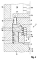
- FIG. 4 illustrated embodiment of a fuel injector according to the invention differs from that of FIG. 1 essentially by that the stationary sealing body 5 has a piston-shaped portion 24, which projects into the switching valve chamber 4 such that it undergoes a significant reduction in its volume. A substantial part of the volume of the switching valve chamber 4 is reduced to an annular space surrounding the piston-shaped section 24.
- the fuel present in the switching valve chamber 4 is fed via the annular space to the bores 17 which hydraulically connect the switching valve chamber 4 with the return flow 18 formed in the holding body 19.
- For the proposed flow path of the fuel allows only the formation of a centrally projecting into the switching valve chamber 4 piston-shaped portion 24 of the stationary sealing body 5 as a packing, which leads to a minimization of the volume.
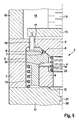
- FIG. 5 shown further embodiment of a fuel injector according to the invention differs from that in the FIG. 1 essentially only in that the inner contour of the sleeve-shaped closing element 3 is designed to form the sealing contour 6 at least partially spherical.
- the valve seat 8 is thus formed as a ball-and-cone seat.
- the in the FIG. 5 shown valve seat geometry is selected only by way of example.
- the closing element 3 may be formed on the stationary sealing body 5, an at least partially spährisch extending outer contour for forming the sealing contour 7.
- other seat geometries by appropriate design of the inner or outer contour on the closing element 3 and the sealing body 5 are possible.
- FIGS. 1 to 5 shown concrete embodiments have features that are arbitrarily combinable or interchangeable, so that a variety of other embodiments of a fuel injector according to the invention can be realized.
Landscapes
- Engineering & Computer Science (AREA)
- Chemical & Material Sciences (AREA)
- Combustion & Propulsion (AREA)
- Mechanical Engineering (AREA)
- General Engineering & Computer Science (AREA)
- Physics & Mathematics (AREA)
- Fluid Mechanics (AREA)
- Fuel-Injection Apparatus (AREA)
Abstract
Description
- Die Erfindung betrifft einen Kraftstoffinjektor mit den Merkmalen des Oberbegriffs des Anspruchs 1. Ein derartiger Kraftstoffinjektor weist ein Gehäuseteil auf, in welches ein mittels eines Piezoaktors betätigbares Schaltventil mit einem hubbeweglichen Schließelement aufgenommen ist. Das Schließelement ist zur Ausbildung eines Schaltventilraums und zur wenigstens teilsweisen Aufnahme eines stationären Dichtkörpers hülsenförmig ausgebildet und besitzt eine erste Dichtkontur, die mit einer an dem stationären Dichtkörper ausgebildeten zweiten Dichtkontur als Ventilsitz zusammenwirkt.
- Ein gattungsgemäßer Kraftstoffinjektor geht aus der Offenlegungsschrift
DE 10 2006 049 831 A1 hervor. Der hierin beschriebene Kraftstoffinjektor weist ein Schaltventil sowie einen mehrteiligen Piezoaktor zur Betätigung des Schaltventils auf. Das Schaltventil umfasst ein hülsenförmig ausgebildetes Ventilelement sowie einen stationären Kolben, der in dem Ventilelement aufgenommen ist. Zwischen dem stationären Kolben und dem Ventielement ist ein Schaltventilraum ausgebildet, der über einen Ablaufkanal und eine Ablaufdrossel mit einem Steuerraum hydraulisch verbunden ist. Der Ablaufkanal ist durch den stationären Kolben hindurchgeführt und mündet über seitliche Bohrungen in den vom hülsenförmigen Ventilelement umschlossenen Schaltventilraum. Über eine am Ventilelement ausgebildete erste Dichtkontur, welche mit einer am stationären Kolben ausgebildeten zweiten Dichtkontur zusammenwirkt, wird ein den Schaltventilraum verschließender Ventilsitz ausgebildet. Das Schaltventil ist weitgehend druckausgeglichen ausgeführt, indem der im Ventilelement aufgenommene Führungsdurchmesser des stationären Kolbens gleich dem Durchmesser im Bereich seiner Dichtkontur gewählt ist. In Schließstellung des Schaltventils wirken demnach im Wesentlichen nur radiale Kräfte auf das Ventilelement ein. Dies führt zu einer Reduzierung der zur Betätigung des Schaltventils erforderlichen Kraft, so dass auch die Kraft des Piezoaktors reduziert werden kann. Der vorliegend mehrteilig ausgeführte Piezoaktor ist derart angeordnet, dass er bzw. ein den Piezoaktor aufnehmender Trägerkörper das Ventilelement umgibt. Dadurch wird ein in axialer Richtung kompaktbauender Kraftstoffinjektor geschaffen. Ferner zeichnet sich der bekannte Kraftstoffinjektor durch ein geringes Schaltventilraumvolumen aus. Ein geringes Volumen stellt einen schnellen Druckanstieg im Schaltventilraum und damit schnelle Schaltzeiten sicher. Die Vorteile eines geringen Schaltventilraumvolumens werden bei dem bekannten Kraftstoffinjektor jedoch zum Teil dadurch wieder aufgehoben, dass der durch den stationären Kolben geführte Ablaufkanal ein zusätzliches zu füllendes Volumen darstellt. Mit dem Volumen des Schaltventilraums steigt auch die Steuermenge an, so dass der Wirkungsgrad des Kraftstoffinjektors eine Verschlechterung erfährt. - Um die Füllzeiten zu verkürzen und darüber schnellere Schaltzeiten zu ermöglichen, sind aus dem Stand der Technik ferner Kraftstoffinjektoren mit Schaltventilen bekannt, welche über Bypass-Bohrungen oder Fülldrosseln zusätzlich an eine Hochdruckversorgung angebunden sind. Zusätzliche Bohrungen erhöhen jedoch den Herstellungsaufwand und damit die Kosten eines Kraftstoffinjektors.
- Der vorliegenden Erfindung liegt daher die Aufgabe zugrunde, einen Kraftstoffinjektor der vorstehend genannten Art dahingehend zu verbessern, dass dieser ein minimiertes Schaltventilraumvolumen aufweist, um den Wirkungsgrad weiter zu verbessern. Ferner soll eine im Wesentlichen druckausgeglichene Ausführung des Schaltventils realisierbar sein.
- Die Augabe wird gelöst durch einen Kraftstoffinjektor mit den Merkmalen des Anspruchs 1. Vorteilhafte Weiterbildungen der Erfindung werden in den Unteransprüchen angegeben.
- Erfindungsgemäß ist eine Dichthülse zur radialen Begrenzung des Schaltventilraums vorgesehen, die zumindest teilweise in dem hülsenförmig ausgebildeten Schließelement aufgenommen und mittels einer Druckfeder gegenüber einer Drosselplatte axial vorgespannt ist. Die Dichthülse stellt somit die Abdichtung des Schaltventilraums gegenüber der Drosselplatte und dem hierin ausgebildeten Ablaufkanal bzw. der hierin ausgebildeten Ablaufdrossel sicher. Der abströmende Kraftstoff gelangt über die Ablaufdrossel und den auf die Drosselplatte beschränkten Ablaufkanal direkt in den Schaltventilraum, so dass aufwendig durch einen stationären Dichtkörper geführte Bohrungen, die zudem ein zusätzliches zu befüllendes Volumen darstellen, entfallen können. Zugleich dient die in dem hülsenförmigen Schließelement aufgenommene Dichthülse als Füllkörper, durch den das Volumen des Schaltventilraums weiter verringert wird. Es wird somit ein Kraftstoffinjektor mit einem schnell schaltenden Schaltventil geschaffen, der zu einer Verbesserung des Wirkungsgrades des Gesamtsystems beiträgt.
- Darüber hinaus ermöglicht die Dichthülse eine weitgehend druckausgeglichene Ausführung des Schaltventils. Denn die im Schließelement aufgenommene Dichthülse verhindert, dass in Schließstellung des Schaltventils die Stirnflächen des Schließelementes von einer Axialkraft beaufschlagt werden. Durch eine zylinderförmige Innenkontur des Schließelementes kann zudem sichergestellt werden, dass ausschließlich Radialkräfte auf das Schließelement einwirken. Die Innenkontur des Schließelementes kann darüber hinaus bewusst auch derart gestaltet sein, dass eine Druckstufe in Form eines radial verlaufenden Absatzes ausgebildet wird.
- Bevorzugt ist die Dichthülse zur dichtenden Anlage an der Drosselplatte mit einer Beißkante ausgestattet. Die Beißkante verbessert aufgrund ihrer ringförmigen Dichtkontur den Dichtsitz der Dichthülse gegenüber der Drosselplatte. Weiterhin bevorzugt ist die Beißkante im Bereich des Innendurchmessers der Dichthülse ausgebildet. Dies besitzt den Vorteil, dass die der Drosselplatte zugewandte Stirnfläche der Dichthülse nicht von Hochdruck beaufschlagt wird und eine Druckkraft auf die Dichthülse ausübt, welche einer dichtenden Anlage an der Drosselplatte entgegen wirkt. Soll die Dichthülse dagegen von einer Druckkraft beaufschlagt werden, die in Richtung der Drosselplatte wirkt, kann die der Beißkante gegenüberliegende Stirnfläche mit Hochdruck beaufschlagt und damit als Druckstufe eingesetzt werden. Alternativ oder ergänzend ist auch die Ausbildung einer Druckstufe in Form eines radial verlaufenden Absatzes möglich. Aufgrund der zusätzlich auf die Dichthülse einwirkenden Druckkraft in Richtung der Drosselplatte kann dementsprechend die Federkraft der die Dichthülse baufschlagenden Druckfeder reduziert werden.
- Weiterhin bevorzugt ist das hülsenförmig ausgebildete Schließelement mittels einer Druckfeder gegenüber dem Dichtkörper axial vorgespannt. Die Federkraft dieser Druckfeder kann reduziert werden, wenn am Schließelement eine Druckstufe in Form eines radial verlaufenden Absatzes ausgebildet ist. Vorteilhafterweise ist die Druckfeder außerhalb des Schaltventilraums angeordnet, um das Volumen des Schaltventilraums möglichst gering zu halten. Denn eine außenliegende Anordnung der Druckfeder ermöglicht eine Verringerung der Durchmesser des Schließelementes und der Dichthülse. Alternativ kann auch auf eine zusätzliche außenseitig angeordnete Druckfeder verzichtet werden, wenn die Druckfeder, mittels welcher die Dichthülse gegenüber der Drosselplatte axial vorgespannt ist, zugleich an dem Schließelement abgestützt ist. Hierzu kann die innerhalb des Schaltventilraums angeordnete Druckfeder als Schraubenfeder, Tellerfeder oder gewellte Federscheibe ausgebildet sein. Letztere erfordern gegenüber einer Schraubenfeder einen geringeren axialen Bauraum, was wiederum eine Reduzierung des Schaltventilraumvolumens ermöglicht.
- Gemäß einer bevorzugten Ausführungsform der Erfindung ist der Piezoaktor zur Betätigung des Schaltventils über eine Platte und mehrere bolzenförmige Übertragungselemente mit dem Schließelement wirkverbunden. Die bolzenförmigen Übertragungselemente sind auf der Platte vorzugsweise entlang einer Kreislinie im gleichen Winkelabstand zueinander angeordnet, wobei der Durchmesser der Kreislinie derart auf den Außendurchmesser des Schließelementes abgestimmt ist, dass die bolzenförmigen Übertragungselemente an einer ringförmigen Stirnfläche des Schließelementes anliegen. Die Kraft und der Hub des Aktors wird somit über die Platte und die Übertragungselemente auf das Schließelement übertragen.
- Weiterhin bevorzugt ist der Piezoaktor außerhalb des Gehäuseteils angeordnet und die Übertragungselemente sind durch Bohrungen des Gehäuseteils geführt, welche zugleich der hydraulischen Verbindung des Schaltventilraums mit einem Rücklauf dienen. Durch die Doppelfunktion der im Gehäuseteil vorgesehenen Bohrungen wird der konstruktive Aufbau und damit die Herstellung des Injektors vereinfacht. Die Anordnung des Piezoaktors außerhalb des das Schaltventil aufnehmenden Gehäuseteils vereinfacht eine ggf. erwünschte Abdichtung des Aktors gegenüber dem Kraftstoff. Darüber hinaus wird der elektrische Anschluss des Piezoaktors erleichtert, da die zum Aktor führenden elektrischen Anschlussleitungen nicht durch mehrere Gehäuseteile hindurch geführt werden müssen.
- Der Ventilsitz des Schaltventils kann als Kegel-Kegel-Sitz oder als Kugel-Kegel-Sitz ausgeführt werden. In entsprechender Weise sind die an dem Schließelement und dem Dichtkörper ausgebildeten Dichtkonturen gestaltet. Das heißt, dass das hubbewegliche Schließelement vorzugsweise eine zumindest teilweise konisch oder sphärisch verlaufende Innenkontur zur Ausbildung der Dichtkontur besitzt. Das heißt ferner, dass der stationäre Dichtkörper vorzugsweise eine zumindest teilweise konisch oder sphärische verlaufende Außenkontur zur Ausbildung der Dichtkontur besitzt.
- Vorteilhafterweise besitzt der stationäre Dichtkörper darüber hinaus einen in den Schaltventilraum hineinragenden kolbenförmigen Abschnitt. In Abhängigkeit von den jeweils gewählten Abmessungen vermag der kolbenförmige in den Schaltventilraum hineinragende Anschnitt eine deutliche Verkleinerung des Schaltventilraumvolumens zu bewirken. Der kolbenförmige Abschnitt dient somit ebenfalls als Füllkörper, welcher das Schaltventilraumvolumen auf einen Ringraum begrenzt.
- Gemäß einer weiteren bevorzugten Ausführungsform ist der stationäre Dichtkörper einstückig mit dem das Schaltventil aufnehmenden Gehäuseteil ausgebildet. Durch die einstückige Ausbildung können die Herstellungs- bzw. Montagekosten verringert werden.
- Bevorzugte Ausführungsformen der Erfindung werden nachfolgend anhand der beigefügten Zeichnungen näher erläutert. Diese zeigen:
- Figur 1
- einen Ausschnitt eines Längsschnitts durch eine erste Ausführungsform,
- Figur 2
- einen Ausschnitt eines Längsschnitts durch eine zweite Ausführungform,
- Figur 3
- einen Ausschnitt eines Längsschnitts durch eine dritte Ausführungsform,
- Figur 4
- einen Ausschnitt eines Längsschnitts durch eine vierte Ausführungform und
- Figur 5
- einen Ausschnitt eines Längsschnitts durch eine fünfte Ausführungsform eines erfindungsgemäßen Kraftstoffinjektors im Bereich des Schaltventils.
- Bei dem in der
Figur 1 dargestellten ersten Ausführungsbeispiel eines erfindungsgemäßen Kraftstoffinjektors umfasst das in einem Gehäuseteil 1 angeordnete Schaltventil 2 ein hülsenförmiges Schließelement 3, welches gegenüber einem stationären Dichtkörper 5, das zumindest teilweise in dem hülsenförmigen Schließelement 3 aufgenommen ist, hubbeweglich gelagert ist. Eine an dem Schließelement 3 ausgebildete erste Dichtkontur 6 wirkt mit einer zweiten Dichtkontur 7 zusammen, welche an dem stationären Dichtkörper 5 ausgebildet ist. Die erste Dichtkontur 6 und die zweite Dichtkontur 7 bilden somit einen Ventilsitz 8 aus. Zur Ausbildung der Dichtkonturen 6, 7 sind die Innenkontur des hülsenförmigen Schließelementes 3 und die Außenkontur des stationären Dichtkörpers 5 jeweils über einen Teilbereich konisch verlaufend ausgeführt. Das Schaltventil 2 umfasst ferner einer Dichthülse 9, welche über eine Beißkante 12 an einer Drosselplatte 11 dichtend anliegt. - Die Dichthülse 9 ist in dem hülsenförmigen Schließelement 3 aufgenommen, so dass ein innerhalb des Schließelementes 3 ausgebildeter Schaltventilraum 4 eine Verkleinerung erfährt. Mittels einer Druckfeder 10 in Form einer Schraubenfeder ist die Dichthülse 9 gegenüber der Drosselplatte 11 axial vorgespannt. Die Druckfeder 10 ist hierzu einerseits an der Dichthülse 9, andererseits an dem stationären Dichtkörper 5 abgestützt. Ein an der Dichthülse 9 ausgebildeter radialer Absatz dient der Druckfeder 10 als Stützfläche. Zugleich bildet der radiale Absatz eine hochdruckbeaufschlagte Druckstufe 23 aus, die eine zusätzliche Anpresskraft der Dichthülse 9 gegenüber der Drosselplatte 11 bewirkt.
- Eine weitere Druckstufe 22 in Form eines radialen Absatzes ist an dem hülsenförmigen Schließelement 3 ausgebildet. Hierdurch wird das Schließelement 3 in Schließrichtung mit einer zusätzlichen Druckkraft beaufschlagt. Entsprechend geringer kann die Federkraft einer das Schließelement 3 ebenfalls in Schließrichtung beaufschlagenden Druckfeder 13 ausgebildet sein, die in dem vorliegenden Ausführungsbeispiel außenumfangsseitig angeordnet ist und einerseits an einem radial verlaufenden Absatz des Schließelementes 3 und andererseits an der Drosselplatte 11 abgestützt ist. Die außenumfangsseitige Anordnung der Druckfeder 13 ermöglicht eine Verringerung der Durchmesser der Dichthülse 9 und des Schließelementes 3, so dass auch das Volumen des Schaltventilraums 4 verringert wird.
- Zur Betätigung des Schaltventils 2 ist ein in einem Haltekörper 19 angeordneter Piezoaktor 14 vorgesehen, der über eine Platte 15 und mehrere hierauf angeordnete bolzenförmige Übertragungselemente 16 mit dem Schließelement 3 des Schaltventils 2 wirkverbunden ist. Aufgrund der Anordnung des Piezoaktors 14 in einem separaten Gehäuseteil sind in dem Gehäuseteil 1 Bohrungen 17 vorgesehen, durch welche die bolzenförmigen Übertragungselemente 16 bis an das Schließelement 3 herangeführt werden können. Die Bohrungen 17 sind entlang einer Kreislinie in gleichem Winkelabstand zueinander angeordnet, wobei der Durchmesser der Kreislinie auf den Durchmesser des hülsenförmigen Schließelementes 3 derart abgestimmt ist, dass die durch die Bohrungen 17 geführten bolzenförmigen Übertragungselemente 16 an einer ringförmigen Stirnfläche des Schließelementes 3 anliegen. Dabei sind die Innendurchmesser der Bohrungen 17 geringfügig größer als die Außendurchmesser der bolzenförmigen Übertragungselemente 16 gewählt, so dass der Schaltventilraum 4 über die Bohrungen 17 zugleich mit einem im Haltekörper 19 ausgebildeten Rücklauf 18 hydraulisch verbindbar ist.
- Das Gehäuseteil 1 bildet zugleich den stationären Dichtkörper 5 aus. Das heißt, dass der stationäre Dichtkörper 5 an das Gehäuseteil 1 angeformt ist.
- Die Funktionsweise des Kraftstoffinjektors ist wie folgt: Zum Öffnen des Schaltventils 2 wird der Piezoaktor 14 bestromt, der sich aufgrund der Bestromung ausdehnt. Dabei bewegt der Piezoaktor 14 die Platte 15 einschließlich der bolzenförmigen Übertragungselemente 16 in Richtung der Drosselplatte 11. Aufgrund des direkten Kontaktes der bolzenförmigen Übertragungselemente 16 mit dem hülsenförmigen Schließelement 3 wird auch dieses entgegen der Druckkraft der Druckfeder 13 in Richtung der Drosselplatte 11 bewegt, wobei das Schließelement 3 vom Ventilsitz 8 abhebt und das Schaltventil 2 öffnet. Im Schaltventilraum 4 befindlicher Kraftstoff kann nunmehr über die Dichtkonturen 6, 7 hinweg zu den Bohrungen 17 und damit zum Rücklauf 18 strömen. Über die im Bereich des Ventilsitzes 8 ringförmige Abströmfläche wird der abströmende Kraftstoff bzw. die Absteuermenge nach radial außen den Bohrungen 17 zugeführt. Ein solcher Strömungsweg besitzt Vorteile, welche im Zusammenhang mit einem nachfolgenden Ausführungsbeispiel noch näher erläutert werden.
- In Offenstellung des Schaltventils 2 bewirkt der aus dem Schaltventilraum 4 abströmende Kraftstoff einen Druckabfall, der sich ebenfalls in einem mit dem Schaltventilraum 4 hydraulisch verbundenen Steueraum (nicht dargestellt) einstellt. Zur hydraulischen Verbindung des Steuerraums mit dem Schaltventilraum 4 ist in der Drosselplatte 11 ein Ablaufkanal 20 mit einer Ablaufdrossel 21 vorgesehen. Die Druckentlastung im Steuerraum ermöglicht einen Öffnungshub einer Düsennadel (nicht dargestellt) durch welche wenigstens eine Einspritzöffnung (nicht dargestellt) des Kraftstoffinjektors freigegeben wird.
- Wird die Bestromung des Piezoaktors 14 beendet, zieht sich dieser wieder zusammen, so dass die Platte 15 einschließlich der bolzenförmigen Übertragungselemente 16 in ihre Ausgangsstellung zurück bewegt werden, wobei die Druckfeder 13 das Schließelement 3 gegen den Ventilsitz 8 zurückstellt. In Schließstellung des Steuerventils 2 vermag sich im Steueraum und im Schaltventilraum wieder ein Druck aufzubauen, der die Düsennadel mit einer Druckkraft in Schließrichtung beaufschlagt. Durch die zusätzliche Kraft einer Feder wird die Düsennadel in ihren Dichtsitz zurückgestellt und die wenigstens eine Einspritzöffnung wieder verschlossen, so dass der Einspritzvorgang beendet ist.
- Durch das erfindungsgemäß vorgesehene geringe Schaltventilraumvolumen des Schaltventils 2 kann eine schneller Druckanstieg bei geschlossenem Schaltventil 2 bewirkt werden. Der Kraftstoffinjektor zeichnet sich demnach durch kurze Schaltzeiten aus. Zudem wird aufgrund des geringen Schaltventilraumvolumens die Steuermenge reduziert, was wiederum zu einer Verbesserung des Wirkungsgrades führt. Da ein schneller Durckanstieg gewährleistet ist, können zusätzliche Bypassbohrungen oder Fülldrosseln zur Verkürzung der Füllzeit entfallen. Auch diese Maßnahme fürhrt wiederum zu einer Verringerung der Steuermenge.
- Das in der
Figur 2 dargestellte Ausführungsbeispiel eines erfindungsgemäßen Kraftstoffinjektors unterscheidet sich von dem derFigur 1 im Wesentlichen darin, dass das hülsenförmig ausgebildete Schließelement 3 keinen als Druckstufe 22 ausgebildeten radialen Absatz aufweist. Die Innenkontur des hülsenförmigen Schließelementes 3 ist bis zur Dichtkontur 6 zylindrisch ausgebildet, so dass in Schließstellung des Schaltventils 2 das Schließelement 3 über den im Schaltventilraum 4 vorhandenen Kraftstoff mit einer lediglich in radialer Richtung wirkenden Druckkraft beaufschlagt wird. Das Schaltventil 2 ist somit im Wesentlichen druckausgeglichen. Die Ausführung des Schaltventils 2 als druckausgeglichenes Ventil senkt den Kraftbedarf zur Betätigung des Schaltventils 2. Die Reduzierung des Kraftbedarfs kann dazu genutzt werden, einen Piezoaktor 14 geringerer Baugröße einzusetzen, den Energiebedarf des Piezoaktors 14 zu verringern oder die Dynamik des Piezoaktors 14 zu erhöhen. Zugleich können geringe Schaltzeiten bewirkt werden. - Bei der in der
Figur 3 dargestellten Ausführungsform eines erfindungsgemäßen Kraftstoffinjektors ist im Unterschied zu der Ausführungsform derFigur 3 wiederum eine Druckstufe 22 an der Innenkontur des hülsenförmigen Schließelementes 3 ausgebildet, an welcher zugleich die Druckfeder 10 abgestützt ist, mittels welcher die Dichthülse 9 in Anlage mit der Drosselplatte 11 gehalten wird. Die vorliegende Ausführungsform macht eine zusätzliche Druckfeder 13 entbehrlich, so dass das Schaltventil 2 insbesondere in radialer Richtung sehr kompaktbauend ist. Um auch in axialer Richtung eine kompakte Bauform zu erhalten, ist die Druckfeder 10 vorliegend als gewellte Federscheibe ausgebildet, die einerseits an der Druckstufe 22 des Schließelementes 3 und andererseits an einer ringförmigen Stirnfläche der Dichthülse 9 abgestützt ist. Die Dichthülse 9 weist darüber hinaus keinen als Druckstufe 23 dienenden radialen Absatz auf, da die ringfömige Stirnfläche eine Druckstufe 23 ersetzt. Die Ausführungsform derFigur 3 zeichnet sich demnach durch eine reduzierte Anzahl an Bauteilen sowie einer Vereinfachung der Bauteilformen aus. - Die in der
Figur 4 dargestellte Ausführungsform eines erfindungsgemäßen Kraftstoffinjektors unterscheidet sich von der derFigur 1 im Wesentlichen dadurch, dass der stationäre Dichtkörper 5 einen kolbenförmigen Abschnitt 24 besitzt, der in den Schaltventilraum 4 derart hineinragt, dass dieser eine deutliche Verringerung seines Volumens erfährt. Ein wesentlicher Teil des Volumens des Schaltventilraums 4 wird auf einen den kolbenfömigen Abschnitt 24 umgebenden Ringraum reduziert. Über den Ringraum wird in Offenstellung des Schaltventils 2 der im Schaltventilraum 4 vorhandene Kraftstoff den Bohrungen 17 zugeführt, welche den Schaltventilraum 4 mit dem im Haltekörper 19 ausgebildeten Rücklauf 18 hydraulisch verbinden. Hier zeigt sich nunmehr der Vorteil eines ringförmigen Abströmquerschnittes, über welchen der abströmende Kraftstoff nach radial außen geführt wird. Denn der vorgeschlagene Strömungsweg des Kraftstoffs ermöglicht erst die Ausbildung eines zentral in den Schaltventilraum 4 hineinragenden kolbenförmigen Abschnitt 24 des stationären Dichtkörpers 5 als Füllkörper, der zu einer Minimierung des Volumens führt. - Die in der
Figur 5 dargestellte weitere Ausführungsform eines erfindungsgemäßen Kraftstoffinjektors unterscheidet sich von dem in derFigur 1 im Wesentlichen lediglich dadurch, dass die Innenkontur des hülsenförmig ausgebildeten Schließelementes 3 zur Ausbildung der Dichtkontur 6 zumindest teilweise sphärisch verlaufend ausgeführt ist. Der Ventilsitz 8 ist somit als Kugel-Kegel-Sitz ausgebildet. Die in derFigur 5 dargestellte Ventilsitzgeometrie ist lediglich beispielhaft gewählt. Anstelle des Schließelementes 3 kann auch an dem stationären Dichtkörper 5 eine zumindest teilweise spährisch verlaufende Außenkontur zur Ausbildung der Dichtkontur 7 ausgebildet sein. Darüber hinaus sind auch andere Sitzgeometrien durch entsprechende Ausbildung der Innen- bzw. Außenkontur am Schließelement 3 bzw. dem Dichtkörper 5 möglich. - Des Weiteren wird darauf hingewiesen, dass die in den
Figuren 1 bis 5 dargestellten konkreten Ausführungsformen Merkmale aufweisen, die beliebig kombinierbar oder austauschbar sind, so dass eine Vielzahl weiterer Ausführungsformen eines erfindungsgemäßen Kraftstoffinjektors realisierbar sind.
Claims (9)
- Kraftstoffinjektor mit einem Gehäuseteil (1), in welches ein mittels eines Piezoaktors (14) betätigbares Schaltventil (2) mit einem hubbeweglichen Schließelement (3) aufgenommen ist, wobei das Schließelement (3) zur Ausbildung eines Schaltventilraums (4) und zur wenigstens teilweisen Aufnahme eines stationären Dichtkörpers (5) hülsenförmig ausgebildet ist und eine erste Dichtkontur (6) besitzt, die mit einer an dem stationären Dichtkörper (5) ausgebildeten zweiten Dichtkontur (7) als Ventilsitz (8) zusammenwirkt,
dadurch gekennzeichnet, dass ferner eine Dichthülse (9) zur radialen Begrenzung des Schaltventilraums (4) vorgesehen ist, die zumindest teilweise in dem hülsenförmig ausgebildeten Schließelement (3) aufgenommen und mittels einer Druckfeder (10) gegenüber einer Drosselplatte (11) axial vorgespannt ist. - Kraftstoffinjektor nach Anspruch 1,
dadurch gekennzeichnet, dass zur dichtenden Anlage an der Drosselplatte (11) die Dichthülse (9) mit einer Beißkante (10) ausgestattet ist, die vorzugsweise im Bereich des Innendurchmessers der Dichthülse (9) ausgebildet ist. - Kraftstoffinjektor nach Anspruch 1 oder 2,
daduch gekennzeichnet, dass das hülsenförmig ausgebildete Schließelement (3) mittels einer Druckfeder (10, 13) gegenüber dem Dichtkörper (5) axial vorgespannt ist, wobei vorzugsweise die Druckfeder (13) außerhalb des Schaltventilraums (4) angeordnet ist. - Kraftstoffinjektor nach einem der vorhergehenden Ansprüche,
dadurch gekennzeichnet, dass der Piezoaktor (14) zur Betätigung des Schaltventils (2) über eine Platte (15) und mehrere bolzenförmige Übertragungselemente (16) mit dem Schließelement (3) wirkverbunden ist. - Kraftstoffinjektor nach Anspruch 4,
dadurch gekennzeichnet, dass der Piezoaktor (14) außerhalb des Gehäuseteils (1) angeordnet ist und die Übertragungselemente (16) durch Bohrungen (17) des Gehäuseteils (1) geführt sind, welche zugleich der hydraulischen Verbindung des Schaltventilraums (4) mit einem Rücklauf (18) dienen. - Kraftstoffinjektor nach einem der vorhergehenden Ansprüche,
dadurch gekennzeichnet, dass das hubbewegliche Schließelement (3) zur Ausbildung der Dichtkontur (6) eine zumindest teilweise konisch oder sphärisch verlaufende Innenkontur besitzt. - Kraftstoffinjektor nach einem der vorhergehenden Ansprüche,
dadurch gekennzeichnet, dass der stationäre Dichtkörper (5) zur Ausbildung der Dichtkontur (7) eine zumindest teilweise konisch oder sphärisch verlaufende Außenkontur besitzt. - Kraftstoffinjektor nach einem der vorhergehenden Ansprüche,
dadurch gekennzeichnet, dass der stationäre Dichtkörper (5) einen in den Schaltventilraum (4) hineinragenden kolbenförmigen Abschnitt (24) besitzt. - Kraftstoffinjektor nach einem der vorhergehenden Ansprüche,
dadurch gekennzeichnet, dass der stationäre Dichtkörper (5) einstückig mit dem das Schaltventil (2) aufnehmenden Gehäuseteil (1) ausgebildet ist.
Applications Claiming Priority (1)
| Application Number | Priority Date | Filing Date | Title |
|---|---|---|---|
| DE201010002639 DE102010002639A1 (de) | 2010-03-08 | 2010-03-08 | Kraftstoffinjektor |
Publications (2)
| Publication Number | Publication Date |
|---|---|
| EP2366887A1 true EP2366887A1 (de) | 2011-09-21 |
| EP2366887B1 EP2366887B1 (de) | 2014-10-22 |
Family
ID=43923759
Family Applications (1)
| Application Number | Title | Priority Date | Filing Date |
|---|---|---|---|
| EP20110153203 Not-in-force EP2366887B1 (de) | 2010-03-08 | 2011-02-03 | Kraftstoffinjektor |
Country Status (2)
| Country | Link |
|---|---|
| EP (1) | EP2366887B1 (de) |
| DE (1) | DE102010002639A1 (de) |
Cited By (1)
| Publication number | Priority date | Publication date | Assignee | Title |
|---|---|---|---|---|
| CN114941678A (zh) * | 2021-02-16 | 2022-08-26 | Zf腓特烈斯哈芬股份公司 | 用于减振器的减振阀装置 |
Citations (3)
| Publication number | Priority date | Publication date | Assignee | Title |
|---|---|---|---|---|
| DE102006049831A1 (de) | 2006-10-23 | 2008-04-24 | Robert Bosch Gmbh | Kraftstoffinjektor mit Piezoaktor |
| DE102006055555A1 (de) * | 2006-11-24 | 2008-05-29 | Robert Bosch Gmbh | Kraftstoffinjektor mit Piezoaktor |
| EP1927748A2 (de) * | 2006-12-01 | 2008-06-04 | Robert Bosch Gmbh | Kraftstoffinjektor |
-
2010
- 2010-03-08 DE DE201010002639 patent/DE102010002639A1/de not_active Withdrawn
-
2011
- 2011-02-03 EP EP20110153203 patent/EP2366887B1/de not_active Not-in-force
Patent Citations (3)
| Publication number | Priority date | Publication date | Assignee | Title |
|---|---|---|---|---|
| DE102006049831A1 (de) | 2006-10-23 | 2008-04-24 | Robert Bosch Gmbh | Kraftstoffinjektor mit Piezoaktor |
| DE102006055555A1 (de) * | 2006-11-24 | 2008-05-29 | Robert Bosch Gmbh | Kraftstoffinjektor mit Piezoaktor |
| EP1927748A2 (de) * | 2006-12-01 | 2008-06-04 | Robert Bosch Gmbh | Kraftstoffinjektor |
Cited By (1)
| Publication number | Priority date | Publication date | Assignee | Title |
|---|---|---|---|---|
| CN114941678A (zh) * | 2021-02-16 | 2022-08-26 | Zf腓特烈斯哈芬股份公司 | 用于减振器的减振阀装置 |
Also Published As
| Publication number | Publication date |
|---|---|
| EP2366887B1 (de) | 2014-10-22 |
| DE102010002639A1 (de) | 2011-09-08 |
Similar Documents
| Publication | Publication Date | Title |
|---|---|---|
| EP3535486B1 (de) | Brennstoffeinspritzventil zum einspritzen eines gasförmigen und/oder flüssigen brennstoffs | |
| EP2715103B1 (de) | Düsenbaugruppe für einen kraftstoffinjektor sowie kraftstoffinjektor | |
| EP2310662B1 (de) | Kraftstoff-injektor | |
| DE102012222043A1 (de) | Kraftstoffinjektor | |
| WO2014000961A1 (de) | Kraftstoffinjektor mit magnetaktor | |
| DE102008001907A1 (de) | Kraftstoff-Injektor | |
| DE102014225392A1 (de) | Düsenbaugruppe für einen Kraftstoffinjektor sowie Kraftstoffinjektor | |
| DE102014217441A1 (de) | Elektromagnetisch betätigbares Proportionalventil | |
| EP2366887B1 (de) | Kraftstoffinjektor | |
| EP3380715B1 (de) | Kraftstoff-injektor | |
| EP2472096A1 (de) | Einspritzventil zum Einspritzen eines Fluids | |
| DE102009027494A1 (de) | Kraftstoff-Injektor mit druckausgeglichenem Steuerventil | |
| EP2256332B1 (de) | Kraftstoffinjektor mit Druckverstärkerkolben | |
| EP2218906B1 (de) | Kraftstoffinjektor | |
| EP2226490B1 (de) | Kraftstoffinjektor | |
| EP2905458B1 (de) | Düsenbaugruppe für einen kraftstoffinjektor sowie kraftstoffinjektor | |
| EP2957760B1 (de) | Düsenbaugruppe für einen kraftstoffinjektor sowie kraftstoffinjektor | |
| DE102010039116A1 (de) | Kraftstoffinjektor | |
| DE102008040161A1 (de) | Magnetventil für einen Kraftstoff-Injektor sowie Kraftstoff-Injektor | |
| DE102005035671B4 (de) | Kraftstoffinjektor für eine Brennkraftmaschine | |
| DE102022209217A1 (de) | Kraftstoffpumpe, insbesondere Hochdruck-Kraftstoffpumpe, für ein Kraftstoffsystem einer Brennkraftmaschine | |
| WO2017067715A1 (de) | Elektromagnetisch betätigbares einlassventil und hochdruckpumpe mit einlassventil | |
| DE102008002470A1 (de) | Einspritzventilglied für Kraftstoffinjektor | |
| EP2400144A2 (de) | Kraftstoffinjektor | |
| DE102017201803A1 (de) | Elektromagnetisch betätigbares Einlassventil und Hochdruckpumpe mit Einlassventil |
Legal Events
| Date | Code | Title | Description |
|---|---|---|---|
| PUAI | Public reference made under article 153(3) epc to a published international application that has entered the european phase |
Free format text: ORIGINAL CODE: 0009012 |
|
| AK | Designated contracting states |
Kind code of ref document: A1 Designated state(s): AL AT BE BG CH CY CZ DE DK EE ES FI FR GB GR HR HU IE IS IT LI LT LU LV MC MK MT NL NO PL PT RO RS SE SI SK SM TR |
|
| AX | Request for extension of the european patent |
Extension state: BA ME |
|
| 17P | Request for examination filed |
Effective date: 20120321 |
|
| GRAP | Despatch of communication of intention to grant a patent |
Free format text: ORIGINAL CODE: EPIDOSNIGR1 |
|
| INTG | Intention to grant announced |
Effective date: 20140724 |
|
| GRAS | Grant fee paid |
Free format text: ORIGINAL CODE: EPIDOSNIGR3 |
|
| GRAA | (expected) grant |
Free format text: ORIGINAL CODE: 0009210 |
|
| AK | Designated contracting states |
Kind code of ref document: B1 Designated state(s): AL AT BE BG CH CY CZ DE DK EE ES FI FR GB GR HR HU IE IS IT LI LT LU LV MC MK MT NL NO PL PT RO RS SE SI SK SM TR |
|
| REG | Reference to a national code |
Ref country code: GB Ref legal event code: FG4D Free format text: NOT ENGLISH |
|
| REG | Reference to a national code |
Ref country code: CH Ref legal event code: EP |
|
| REG | Reference to a national code |
Ref country code: AT Ref legal event code: REF Ref document number: 692786 Country of ref document: AT Kind code of ref document: T Effective date: 20141115 |
|
| REG | Reference to a national code |
Ref country code: IE Ref legal event code: FG4D Free format text: LANGUAGE OF EP DOCUMENT: GERMAN |
|
| REG | Reference to a national code |
Ref country code: DE Ref legal event code: R096 Ref document number: 502011004729 Country of ref document: DE Effective date: 20141204 |
|
| REG | Reference to a national code |
Ref country code: NL Ref legal event code: VDEP Effective date: 20141022 |
|
| REG | Reference to a national code |
Ref country code: LT Ref legal event code: MG4D |
|
| PG25 | Lapsed in a contracting state [announced via postgrant information from national office to epo] |
Ref country code: PT Free format text: LAPSE BECAUSE OF FAILURE TO SUBMIT A TRANSLATION OF THE DESCRIPTION OR TO PAY THE FEE WITHIN THE PRESCRIBED TIME-LIMIT Effective date: 20150223 Ref country code: ES Free format text: LAPSE BECAUSE OF FAILURE TO SUBMIT A TRANSLATION OF THE DESCRIPTION OR TO PAY THE FEE WITHIN THE PRESCRIBED TIME-LIMIT Effective date: 20141022 Ref country code: IS Free format text: LAPSE BECAUSE OF FAILURE TO SUBMIT A TRANSLATION OF THE DESCRIPTION OR TO PAY THE FEE WITHIN THE PRESCRIBED TIME-LIMIT Effective date: 20150222 Ref country code: LT Free format text: LAPSE BECAUSE OF FAILURE TO SUBMIT A TRANSLATION OF THE DESCRIPTION OR TO PAY THE FEE WITHIN THE PRESCRIBED TIME-LIMIT Effective date: 20141022 Ref country code: NL Free format text: LAPSE BECAUSE OF FAILURE TO SUBMIT A TRANSLATION OF THE DESCRIPTION OR TO PAY THE FEE WITHIN THE PRESCRIBED TIME-LIMIT Effective date: 20141022 Ref country code: NO Free format text: LAPSE BECAUSE OF FAILURE TO SUBMIT A TRANSLATION OF THE DESCRIPTION OR TO PAY THE FEE WITHIN THE PRESCRIBED TIME-LIMIT Effective date: 20150122 Ref country code: FI Free format text: LAPSE BECAUSE OF FAILURE TO SUBMIT A TRANSLATION OF THE DESCRIPTION OR TO PAY THE FEE WITHIN THE PRESCRIBED TIME-LIMIT Effective date: 20141022 |
|
| PG25 | Lapsed in a contracting state [announced via postgrant information from national office to epo] |
Ref country code: HR Free format text: LAPSE BECAUSE OF FAILURE TO SUBMIT A TRANSLATION OF THE DESCRIPTION OR TO PAY THE FEE WITHIN THE PRESCRIBED TIME-LIMIT Effective date: 20141022 Ref country code: LV Free format text: LAPSE BECAUSE OF FAILURE TO SUBMIT A TRANSLATION OF THE DESCRIPTION OR TO PAY THE FEE WITHIN THE PRESCRIBED TIME-LIMIT Effective date: 20141022 Ref country code: SE Free format text: LAPSE BECAUSE OF FAILURE TO SUBMIT A TRANSLATION OF THE DESCRIPTION OR TO PAY THE FEE WITHIN THE PRESCRIBED TIME-LIMIT Effective date: 20141022 Ref country code: CY Free format text: LAPSE BECAUSE OF FAILURE TO SUBMIT A TRANSLATION OF THE DESCRIPTION OR TO PAY THE FEE WITHIN THE PRESCRIBED TIME-LIMIT Effective date: 20141022 Ref country code: GR Free format text: LAPSE BECAUSE OF FAILURE TO SUBMIT A TRANSLATION OF THE DESCRIPTION OR TO PAY THE FEE WITHIN THE PRESCRIBED TIME-LIMIT Effective date: 20150123 Ref country code: PL Free format text: LAPSE BECAUSE OF FAILURE TO SUBMIT A TRANSLATION OF THE DESCRIPTION OR TO PAY THE FEE WITHIN THE PRESCRIBED TIME-LIMIT Effective date: 20141022 Ref country code: RS Free format text: LAPSE BECAUSE OF FAILURE TO SUBMIT A TRANSLATION OF THE DESCRIPTION OR TO PAY THE FEE WITHIN THE PRESCRIBED TIME-LIMIT Effective date: 20141022 |
|
| REG | Reference to a national code |
Ref country code: DE Ref legal event code: R097 Ref document number: 502011004729 Country of ref document: DE |
|
| PG25 | Lapsed in a contracting state [announced via postgrant information from national office to epo] |
Ref country code: RO Free format text: LAPSE BECAUSE OF FAILURE TO SUBMIT A TRANSLATION OF THE DESCRIPTION OR TO PAY THE FEE WITHIN THE PRESCRIBED TIME-LIMIT Effective date: 20141022 Ref country code: CZ Free format text: LAPSE BECAUSE OF FAILURE TO SUBMIT A TRANSLATION OF THE DESCRIPTION OR TO PAY THE FEE WITHIN THE PRESCRIBED TIME-LIMIT Effective date: 20141022 Ref country code: DK Free format text: LAPSE BECAUSE OF FAILURE TO SUBMIT A TRANSLATION OF THE DESCRIPTION OR TO PAY THE FEE WITHIN THE PRESCRIBED TIME-LIMIT Effective date: 20141022 Ref country code: SK Free format text: LAPSE BECAUSE OF FAILURE TO SUBMIT A TRANSLATION OF THE DESCRIPTION OR TO PAY THE FEE WITHIN THE PRESCRIBED TIME-LIMIT Effective date: 20141022 Ref country code: EE Free format text: LAPSE BECAUSE OF FAILURE TO SUBMIT A TRANSLATION OF THE DESCRIPTION OR TO PAY THE FEE WITHIN THE PRESCRIBED TIME-LIMIT Effective date: 20141022 |
|
| PLBE | No opposition filed within time limit |
Free format text: ORIGINAL CODE: 0009261 |
|
| STAA | Information on the status of an ep patent application or granted ep patent |
Free format text: STATUS: NO OPPOSITION FILED WITHIN TIME LIMIT |
|
| PG25 | Lapsed in a contracting state [announced via postgrant information from national office to epo] |
Ref country code: IT Free format text: LAPSE BECAUSE OF FAILURE TO SUBMIT A TRANSLATION OF THE DESCRIPTION OR TO PAY THE FEE WITHIN THE PRESCRIBED TIME-LIMIT Effective date: 20141022 |
|
| REG | Reference to a national code |
Ref country code: DE Ref legal event code: R119 Ref document number: 502011004729 Country of ref document: DE |
|
| 26N | No opposition filed |
Effective date: 20150723 |
|
| PG25 | Lapsed in a contracting state [announced via postgrant information from national office to epo] |
Ref country code: LU Free format text: LAPSE BECAUSE OF FAILURE TO SUBMIT A TRANSLATION OF THE DESCRIPTION OR TO PAY THE FEE WITHIN THE PRESCRIBED TIME-LIMIT Effective date: 20150203 |
|
| REG | Reference to a national code |
Ref country code: CH Ref legal event code: PL |
|
| GBPC | Gb: european patent ceased through non-payment of renewal fee |
Effective date: 20150203 |
|
| PG25 | Lapsed in a contracting state [announced via postgrant information from national office to epo] |
Ref country code: CH Free format text: LAPSE BECAUSE OF NON-PAYMENT OF DUE FEES Effective date: 20150228 Ref country code: LI Free format text: LAPSE BECAUSE OF NON-PAYMENT OF DUE FEES Effective date: 20150228 Ref country code: MC Free format text: LAPSE BECAUSE OF FAILURE TO SUBMIT A TRANSLATION OF THE DESCRIPTION OR TO PAY THE FEE WITHIN THE PRESCRIBED TIME-LIMIT Effective date: 20141022 |
|
| REG | Reference to a national code |
Ref country code: IE Ref legal event code: MM4A |
|
| REG | Reference to a national code |
Ref country code: FR Ref legal event code: ST Effective date: 20151030 |
|
| PG25 | Lapsed in a contracting state [announced via postgrant information from national office to epo] |
Ref country code: IE Free format text: LAPSE BECAUSE OF NON-PAYMENT OF DUE FEES Effective date: 20150203 Ref country code: DE Free format text: LAPSE BECAUSE OF NON-PAYMENT OF DUE FEES Effective date: 20150901 Ref country code: GB Free format text: LAPSE BECAUSE OF NON-PAYMENT OF DUE FEES Effective date: 20150203 |
|
| PG25 | Lapsed in a contracting state [announced via postgrant information from national office to epo] |
Ref country code: FR Free format text: LAPSE BECAUSE OF NON-PAYMENT OF DUE FEES Effective date: 20150302 Ref country code: SI Free format text: LAPSE BECAUSE OF FAILURE TO SUBMIT A TRANSLATION OF THE DESCRIPTION OR TO PAY THE FEE WITHIN THE PRESCRIBED TIME-LIMIT Effective date: 20141022 |
|
| PG25 | Lapsed in a contracting state [announced via postgrant information from national office to epo] |
Ref country code: MT Free format text: LAPSE BECAUSE OF FAILURE TO SUBMIT A TRANSLATION OF THE DESCRIPTION OR TO PAY THE FEE WITHIN THE PRESCRIBED TIME-LIMIT Effective date: 20141022 |
|
| REG | Reference to a national code |
Ref country code: AT Ref legal event code: MM01 Ref document number: 692786 Country of ref document: AT Kind code of ref document: T Effective date: 20160203 |
|
| PG25 | Lapsed in a contracting state [announced via postgrant information from national office to epo] |
Ref country code: HU Free format text: LAPSE BECAUSE OF FAILURE TO SUBMIT A TRANSLATION OF THE DESCRIPTION OR TO PAY THE FEE WITHIN THE PRESCRIBED TIME-LIMIT; INVALID AB INITIO Effective date: 20110203 Ref country code: BG Free format text: LAPSE BECAUSE OF FAILURE TO SUBMIT A TRANSLATION OF THE DESCRIPTION OR TO PAY THE FEE WITHIN THE PRESCRIBED TIME-LIMIT Effective date: 20141022 Ref country code: SM Free format text: LAPSE BECAUSE OF FAILURE TO SUBMIT A TRANSLATION OF THE DESCRIPTION OR TO PAY THE FEE WITHIN THE PRESCRIBED TIME-LIMIT Effective date: 20141022 Ref country code: AT Free format text: LAPSE BECAUSE OF NON-PAYMENT OF DUE FEES Effective date: 20160203 |
|
| PG25 | Lapsed in a contracting state [announced via postgrant information from national office to epo] |
Ref country code: BE Free format text: LAPSE BECAUSE OF NON-PAYMENT OF DUE FEES Effective date: 20150228 |
|
| PG25 | Lapsed in a contracting state [announced via postgrant information from national office to epo] |
Ref country code: TR Free format text: LAPSE BECAUSE OF FAILURE TO SUBMIT A TRANSLATION OF THE DESCRIPTION OR TO PAY THE FEE WITHIN THE PRESCRIBED TIME-LIMIT Effective date: 20141022 |
|
| PG25 | Lapsed in a contracting state [announced via postgrant information from national office to epo] |
Ref country code: MK Free format text: LAPSE BECAUSE OF FAILURE TO SUBMIT A TRANSLATION OF THE DESCRIPTION OR TO PAY THE FEE WITHIN THE PRESCRIBED TIME-LIMIT Effective date: 20141022 |
|
| PG25 | Lapsed in a contracting state [announced via postgrant information from national office to epo] |
Ref country code: AL Free format text: LAPSE BECAUSE OF FAILURE TO SUBMIT A TRANSLATION OF THE DESCRIPTION OR TO PAY THE FEE WITHIN THE PRESCRIBED TIME-LIMIT Effective date: 20141022 |