EP2226490B1 - Kraftstoffinjektor - Google Patents
Kraftstoffinjektor Download PDFInfo
- Publication number
- EP2226490B1 EP2226490B1 EP10151027A EP10151027A EP2226490B1 EP 2226490 B1 EP2226490 B1 EP 2226490B1 EP 10151027 A EP10151027 A EP 10151027A EP 10151027 A EP10151027 A EP 10151027A EP 2226490 B1 EP2226490 B1 EP 2226490B1
- Authority
- EP
- European Patent Office
- Prior art keywords
- valve
- sleeve
- fuel injector
- coupler
- piston
- Prior art date
- Legal status (The legal status is an assumption and is not a legal conclusion. Google has not performed a legal analysis and makes no representation as to the accuracy of the status listed.)
- Not-in-force
Links
- 239000000446 fuel Substances 0.000 title claims description 37
- 238000002485 combustion reaction Methods 0.000 claims description 8
- 238000003780 insertion Methods 0.000 claims description 7
- 230000037431 insertion Effects 0.000 claims description 7
- 230000008878 coupling Effects 0.000 abstract 5
- 238000010168 coupling process Methods 0.000 abstract 5
- 238000005859 coupling reaction Methods 0.000 abstract 5
- 230000000284 resting effect Effects 0.000 abstract 1
- 238000007789 sealing Methods 0.000 description 5
- 238000010276 construction Methods 0.000 description 4
- 238000004519 manufacturing process Methods 0.000 description 3
- 238000002347 injection Methods 0.000 description 2
- 239000007924 injection Substances 0.000 description 2
- 230000001419 dependent effect Effects 0.000 description 1
- 238000011161 development Methods 0.000 description 1
- 230000018109 developmental process Effects 0.000 description 1
- 239000012530 fluid Substances 0.000 description 1
- 238000000034 method Methods 0.000 description 1
- 230000002093 peripheral effect Effects 0.000 description 1
- 230000002787 reinforcement Effects 0.000 description 1
- 239000013585 weight reducing agent Substances 0.000 description 1
Images

Classifications
-
- F—MECHANICAL ENGINEERING; LIGHTING; HEATING; WEAPONS; BLASTING
- F02—COMBUSTION ENGINES; HOT-GAS OR COMBUSTION-PRODUCT ENGINE PLANTS
- F02M—SUPPLYING COMBUSTION ENGINES IN GENERAL WITH COMBUSTIBLE MIXTURES OR CONSTITUENTS THEREOF
- F02M47/00—Fuel-injection apparatus operated cyclically with fuel-injection valves actuated by fluid pressure
- F02M47/02—Fuel-injection apparatus operated cyclically with fuel-injection valves actuated by fluid pressure of accumulator-injector type, i.e. having fuel pressure of accumulator tending to open, and fuel pressure in other chamber tending to close, injection valves and having means for periodically releasing that closing pressure
- F02M47/027—Electrically actuated valves draining the chamber to release the closing pressure
-
- F—MECHANICAL ENGINEERING; LIGHTING; HEATING; WEAPONS; BLASTING
- F02—COMBUSTION ENGINES; HOT-GAS OR COMBUSTION-PRODUCT ENGINE PLANTS
- F02M—SUPPLYING COMBUSTION ENGINES IN GENERAL WITH COMBUSTIBLE MIXTURES OR CONSTITUENTS THEREOF
- F02M63/00—Other fuel-injection apparatus having pertinent characteristics not provided for in groups F02M39/00 - F02M57/00 or F02M67/00; Details, component parts, or accessories of fuel-injection apparatus, not provided for in, or of interest apart from, the apparatus of groups F02M39/00 - F02M61/00 or F02M67/00; Combination of fuel pump with other devices, e.g. lubricating oil pump
- F02M63/0012—Valves
- F02M63/0014—Valves characterised by the valve actuating means
- F02M63/0015—Valves characterised by the valve actuating means electrical, e.g. using solenoid
- F02M63/0026—Valves characterised by the valve actuating means electrical, e.g. using solenoid using piezoelectric or magnetostrictive actuators
-
- F—MECHANICAL ENGINEERING; LIGHTING; HEATING; WEAPONS; BLASTING
- F02—COMBUSTION ENGINES; HOT-GAS OR COMBUSTION-PRODUCT ENGINE PLANTS
- F02M—SUPPLYING COMBUSTION ENGINES IN GENERAL WITH COMBUSTIBLE MIXTURES OR CONSTITUENTS THEREOF
- F02M63/00—Other fuel-injection apparatus having pertinent characteristics not provided for in groups F02M39/00 - F02M57/00 or F02M67/00; Details, component parts, or accessories of fuel-injection apparatus, not provided for in, or of interest apart from, the apparatus of groups F02M39/00 - F02M61/00 or F02M67/00; Combination of fuel pump with other devices, e.g. lubricating oil pump
- F02M63/0012—Valves
- F02M63/0031—Valves characterized by the type of valves, e.g. special valve member details, valve seat details, valve housing details
- F02M63/0043—Two-way valves
-
- F—MECHANICAL ENGINEERING; LIGHTING; HEATING; WEAPONS; BLASTING
- F02—COMBUSTION ENGINES; HOT-GAS OR COMBUSTION-PRODUCT ENGINE PLANTS
- F02M—SUPPLYING COMBUSTION ENGINES IN GENERAL WITH COMBUSTIBLE MIXTURES OR CONSTITUENTS THEREOF
- F02M63/00—Other fuel-injection apparatus having pertinent characteristics not provided for in groups F02M39/00 - F02M57/00 or F02M67/00; Details, component parts, or accessories of fuel-injection apparatus, not provided for in, or of interest apart from, the apparatus of groups F02M39/00 - F02M61/00 or F02M67/00; Combination of fuel pump with other devices, e.g. lubricating oil pump
- F02M63/0012—Valves
- F02M63/007—Details not provided for in, or of interest apart from, the apparatus of the groups F02M63/0014 - F02M63/0059
-
- F—MECHANICAL ENGINEERING; LIGHTING; HEATING; WEAPONS; BLASTING
- F02—COMBUSTION ENGINES; HOT-GAS OR COMBUSTION-PRODUCT ENGINE PLANTS
- F02M—SUPPLYING COMBUSTION ENGINES IN GENERAL WITH COMBUSTIBLE MIXTURES OR CONSTITUENTS THEREOF
- F02M2200/00—Details of fuel-injection apparatus, not otherwise provided for
- F02M2200/70—Linkage between actuator and actuated element, e.g. between piezoelectric actuator and needle valve or pump plunger
- F02M2200/703—Linkage between actuator and actuated element, e.g. between piezoelectric actuator and needle valve or pump plunger hydraulic
Definitions
- the invention relates to a fuel injector for injecting fuel into a combustion chamber of an internal combustion engine having the features of the preamble of claim 1, such as in the document DE 10 2007 047 426 shown.
- Such fuel injectors are known from the prior art.
- the publication DE 10 2006 042 601 A1 discloses an injector for injecting fuel into a combustion chamber of an internal combustion engine, in which an injection valve member for releasing or closing at least one injection port is driven by an actuator-operated control valve.
- a hydraulic coupler unit is arranged, which in the example known from the prior art comprises a first piston operatively connected to the actuator with a first diameter and a second piston with a second, smaller diameter, so that corresponding to the diameter ratio the two pistons of the stroke of the actuator for controlling the control valve is translated hydraulically.
- Both pistons are guided in a coupler body, which in turn is surrounded by a spring sleeve for axially biasing the first piston relative to the actuator.
- the second piston is biased axially relative to the control valve via a coil spring which is supported on the coupler body.
- a arranged between the actuator and the first piston shim serves to compensate for production-related length tolerances.
- a fuel injector of the type described above has a certain overall construction length due to its complex structure. He may therefore not be used in all internal combustion engines. There is therefore a general interest in reducing the overall construction length of a fuel injector.
- Object of the present invention is to provide such a length-optimized fuel injector with a hydraulic coupler unit, which is also easy and inexpensive to manufacture.
- the control valve of the proposed fuel injector on an extended valve pin with a lying outside the valve plate section forms a guided in a coupler sleeve valve piston of a hydraulic coupler unit.
- the coupler sleeve and the setting piece together define a pressure chamber, which serves as a hydraulic coupler.
- the hydraulic coupler unit of the fuel injector according to the invention has only one piston, which is also still formed by a portion of an extended valve pin.
- a second piston By dispensing with a second piston, a significant reduction in length of the hydraulic coupler unit and thus the total length of the fuel injector can be effected.
- the translation takes place here in the ratio 1: 1, that is, there is no gain of Aktorhubes instead.
- the fuel injector according to the invention therefore preferably has a pressure-compensated control valve whose actuation essentially takes place independently of the system pressure and thus requires a lower pressure force.
- the control valve can be pressure-balanced, for example, in that the valve pin of the control valve is guided on the side facing away from the valve seat in a sleeve, valve closure member and sleeve defining a pressure chamber, which is always depressurized.
- a pressure balanced control valve is the subject of another application of the same applicant and should therefore not be further explored in the context of this application.
- a highly accurate guide for example in the form of a coupler body, is dispensed with. This contributes to the simplification of the hydraulic coupler unit and thus to the cost-effective production of the fuel injector.
- a sufficient guidance of the valve piston is effected in the fuel injector according to the invention via the coupler sleeve.
- a spring element for biasing the coupler sleeve relative to the adjusting piece is further provided.
- the spring element is preferably a coil spring or a spring sleeve.
- the spring force of the spring element ensures a sealing contact of the coupler sleeve on the adjusting piece and thus the sealing of the enclosed by the coupler sleeve, the adjusting piece and the valve piston pressure chamber.
- the coupler sleeve on the upper side facing the spring element has an axially recessed shoulder for supporting the spring element.
- the non-recessed region with a smaller diameter protrudes into the spring element, which thereby experiences a centering.
- the coupler sleeve itself is centered over the valve piston.
- the sealing piece on the adjusting surface of the coupler sleeve is provided with a biting edge.
- the necessary surface pressure for sealing contact is effected by the voltage applied to the coupler sleeve spring element.
- the distance between the radial shoulder and the biting edge of the coupler sleeve is the only degree of tolerance which has an influence on the spring force of the spring element, since the other end of the spring element is supported on the valve plate. Since the influence of this measure is minimal, the already mentioned in connection with the prior art shim for adjusting the spring force can be omitted. Thus, the complex adjustment process itself is unnecessary. By this measure, not only simplifies the construction of the hydraulic coupler unit, but allows by dispensing with a dial further reduction in the length of the coupler unit and thus the total length of the fuel injector.
- a guide gap is provided between the coupler sleeve and serving as a valve piston portion of the valve pin, which is less than 10 microns, preferably less than 5 microns. For one thing is thereby ensuring the sealing of the serving as a hydraulic coupler pressure chamber, on the other hand, a precise guidance of the valve piston in the region of the setting piece.
- the coupler sleeve has on the inner circumference side on the top side facing the spring element a cone-shaped insertion opening for receiving the portion of the valve pin serving as the valve piston. Since the valve piston and the valve pin are integrally formed, the assembly has to be made from the valve seat side. That is, when inserting the valve pin serving as a valve piston portion is inserted through the valve plate and inserted into the coupler. In order to facilitate the insertion, the receiving bore of the coupler sleeve is formed on the valve seat side conical, so that the valve piston is automatically centered during insertion.
- the portion of the valve pin serving as a valve piston has at least one flattening in an area.
- this area is within the valve plate, more preferably in the vicinity of the valve seat.
- the at least one flattening forms a return channel, via which high-pressure fuel can flow out when the control valve is open.
- valve seat valve pin or portion of the valve pin has a spring collar on which a spring element is supported, by means of which the valve pin is biased relative to the valve seat.
- the same spring element simultaneously serves to axially bias the section of the valve pin serving as the valve piston.
- On a separate spring element for the valve piston can therefore be omitted.
- valve pin is furthermore preferably guided at its end facing away from the valve seat in a sleeve, the valve pin, the sleeve and the valve plate defining a low-pressure space.
- the actuation of the valve pin can thus take place essentially system pressure independent, that is, it requires a lower pressure force.
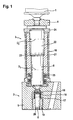
- hydraulic coupler unit 3 comprises two guided in a coupler body 21 piston, a valve piston 8 having a first diameter D 1 and a coupler piston 22 having a second diameter D 2 , wherein D 1 ⁇ D 2 , so that according to the diameter ratio, a translation of the force and the stroke of an actuator 1 via a formed between the two pistons 8, 22 coupler gap 23, which is filled with a hydraulic fluid.
- the coupler body 21 serves to guide the two pistons 8, 22 and is therefore adapted to the inner circumference of the respective piston diameters. With a radially extending collar surface of the coupler body rests against a valve plate 5, in which a control valve 2 is received.
- a pressure-balanced control valve 2 with a valve pin 6, the valve seat facing away end is guided in a sleeve 19 and limited together with the sleeve 19 and the valve plate 5, a low-pressure chamber 20 so that the guided in the sleeve 19 portion of the valve pin 6 of the control valve 2 is not is acted upon by the system pressure.
- a compressive force is required, which essentially corresponds to the spring force of a helical spring 17, by means of which the valve pin 6 is biased relative to the valve seat 18.
- the coil spring 17 is supported on the one hand on the sleeve 19, on the other hand on a spring collar 16 of the valve pin 6.
- the valve piston 8 is also biased by a coil spring 25 relative to the valve pin 6.
- the helical spring 25 is supported on the valve piston 8 and on an inner peripheral side radially extending shoulder of the coupler body 21.
- a second spring element in the form of a spring sleeve 10 is provided, by means of which coupler piston 22 is biased against an adjusting piece 4 and thus relative to the actuator unit 1.
- the spring sleeve 10 is supported on the one hand on a radially extending collar surface of the coupler body 21, on the other hand on a shim 24, which in turn bears against a circumferential radial collar surface of the coupler piston 22.
- the dial 24 is used to adjust the spring force, since the different collar heights of the coupler body 21 and the coupler piston 22 are subject to tolerances.
- a valve piston 8 which is also formed by a portion of an elongated valve pin 6. That is, the valve piston 8 and the valve pin 6 form a component.
- the valve piston 8 is guided only in a coupler sleeve 7, which is biased by a spring element 10 relative to the adjusting piece 4 and thus fixed in position.
- the coupler sleeve 7, the valve piston 8 and the adjusting piece 4 define a pressure chamber 9, which serves as a hydraulic coupler.
- the translation is done in the ratio 1: 1.
- a reinforcement of the force of an actuator of an actuator unit 1 is not required because the control valve 2 is pressure balanced.
- the valve pin 6 of the control valve 2 is guided in a sleeve 19, wherein the sleeve 19, the valve pin 6 and the valve plate 5 define a low-pressure space 20.
- the coupler sleeve 7 is further provided with a biting edge 12, with which the coupler sleeve 7 bears sealingly against the adjusting piece 4.
- the necessary surface pressure is effected by the spring element 10.
- the spring element 10 is a helical spring which is supported on the one hand directly on the valve plate 5, on the other hand on the coupler sleeve 7.
- the coupler sleeve 7 has for this purpose an axially recessed paragraph 11.
- the distance between this paragraph 11 and the adjoining adjoining 4 B formulatekante 12 is the only tolerance-sensitive measure that has an influence on the spring force. Since this influence is minimal, in the case of the hydraulic coupler unit 3 according to the invention, a dial 24 for adjusting the spring force has also been dispensed with.
- the valve pin 6 By a portion of the valve pin 6 at the same time forms the valve piston 8, a further spring element for the axial bias of the valve piston 8 is not required, because the axial position of the valve piston 8 is predetermined by the valve pin 6.
- the structure of the hydraulic simplifies Coupler unit considerably.
- the hydraulic coupler unit serving as a valve piston 8 portion of the valve pin 6 is inserted through the valve plate 5 and inserted into the central bore of the coupler sleeve 7.
- this To facilitate insertion into the coupler sleeve 7, this is provided with a cone-shaped insertion opening 14, so that the valve piston is automatically centered during insertion. This is particularly advantageous because the coupler sleeve 7 serves as a guide for the valve piston 8 and the guide gap 13 has little play.
- valve plate 5 The guided through the valve plate 5 and serving as a valve piston 8 portion of the valve pin 6 has in the example shown a flattening 15 in the region of the valve plate 5, which closely surrounds the valve piston 8 in this area. By the flattening 15, a return passage for fuel under high pressure is formed.
Landscapes
- Engineering & Computer Science (AREA)
- Chemical & Material Sciences (AREA)
- Combustion & Propulsion (AREA)
- Mechanical Engineering (AREA)
- General Engineering & Computer Science (AREA)
- Physics & Mathematics (AREA)
- Fluid Mechanics (AREA)
- Fuel-Injection Apparatus (AREA)
Description
- Die Erfindung betrifft einen Kraftstoffinjektor zum Einspritzen von Kraftstoff in einen Brennraum einer Brennkraftmaschine mit den Merkmalen des Oberbegriffes des Anspruchs 1, wie z.B. in dem Dokument
DE 10 2007 047 426 gezeigt. - Derartige Kraftstoffinjektoren sind aus dem Stand der Technik bekannt. Die Druckschrift
DE 10 2006 042 601 A1 beispielsweise offenbart einen Injektor zum Einspritzen von Kraftstoff in einen Brennraum einer Verbrennungskraftmaschine, bei dem ein Einspritzventilglied zum Freigeben oder Verschließen wenigstens einer Einspritzöffnung durch ein aktorbetätigtes Steuerventil angesteuert wird. Zwischen Aktor und Steuerventil ist eine hydraulische Kopplereinheit angeordnet, die bei dem aus dem Stand der Technik bekannten Beispiel einen mit dem Aktor in Wirkverbindung stehenden ersten Kolben mit einem ersten Durchmesser und einen zweiten Kolben mit einem zweiten, geringeren Durchmesser umfasst, so dass entsprechend dem Durchmesserverhältnis der beiden Kolben der Hub des Aktors zur Steuerung des Steuerventils hydraulisch übersetzt wird. Beide Kolben sind in einem Kopplerkörper geführt, der wiederum von einer Federhülse zur axialen Vorspannung des ersten Kolbens gegenüber dem Aktor umgeben ist. Der zweite Kolben wird über eine Schraubenfeder, die am Kopplerkörper abgestützt ist, gegenüber dem Steuerventil axial vorgespannt. Eine zwischen dem Aktor und dem erstem Kolben angeordnete Einstellscheibe dient dem Ausgleich von fertigungsbedingten Längentoleranzen. - Ein Kraftstoffinjektor der vorstehend beschriebenen Art besitzt aufgrund seines komplexen Aufbaus eine bestimmte Gesamtbaulänge. Er ist damit gegebenenfalls nicht in allen Brennkraftmaschinen einsetzbar. Es besteht daher ein allgemeines Interesse, die Gesamtbaulänge eines Kraftstoffinjektors zu reduzieren.
- Aufgabe der vorliegenden Erfindung ist es, einen solchen längenoptimierten Kraftstoffinjektor mit einer hydraulischen Kopplereinheit anzugeben, der zugleich einfach und kostengünstig herzustellen ist.
- Zur Lösung der Aufgabe wird ein Kraftstoffinjektor mit den Merkmalen des Anspruchs 1 vorgeschlagen. Vorteilhafte Weiterbildungen der Erfindungen sind in den Unteransprüchen angegeben.
- Erfindungsgemäß weist das Steuerventil des vorgeschlagenen Kraftstoffinjektors einen verlängerten Ventilbolzen mit einem außerhalb der Ventilplatte liegenden Abschnitt auf. Dieser Abschnitt bildet einen in einer Kopplerhülse geführten Ventilkolben einer hydraulischen Kopplereinheit aus. Zudem begrenzen der als Ventilkolben dienende Abschnitt des Ventilbolzens, die Kopplerhülse und das Einstellstück gemeinsam einen Druckraum, der als hydraulischer Koppler dient.
- Im Unterschied zur hydraulischen Kopplereinheit des eingangs beschriebenen und aus dem Stand der Technik bekannten Injektors weist die hydraulische Kopplereinheit des erfindungsgemäßen Kraftstoffinjektors lediglich einen Kolben auf, der zudem noch von einem Abschnitt eines verlängerten Ventilbolzens gebildet wird. Durch den Verzicht auf einen zweiten Kolben kann eine deutliche Baulängenreduzierung der hydraulischen Kopplereinheit und damit der Gesamtlänge des Kraftstoffinjektors bewirkt werden. Die Übersetzung erfolgt vorliegend im Verhältnis 1:1, das heißt es findet keine Verstärkung des Aktorhubes statt.
- Bevorzugt weist der erfindungsgemäße Kraftstoffinjektor daher ein druckausgeglichenes Steuerventil auf, dessen Betätigung im Wesentlichen systemdruckunabhängig erfolgt und somit eine geringere Druckkraft erfordert. Das Steuerventil kann beispielsweise dadurch druckausgeglichen sein, dass der Ventilbolzen des Steuerventils auf der dem Ventilsitz abgewandten Seite in einer Hülse geführt ist, wobei Ventilschließglied und Hülse einen Druckraum begrenzen, der stets druckentlastet ist. Ein druckausgeglichenes Steuerventil ist Gegenstand einer anderen Anmeldung derselben Anmelderin und soll daher im Rahmen dieser Anmeldung nicht weiter vertieft werden.
- Des Weiteren wird bei dem erfindungsgemäßen Kraftstoffinjektor im Unterschied zu dem eingangs beschriebenen und aus dem Stand der Technik bekannten Injektor auf eine hochgenaue Führung, beispielsweise in Form eines Kopplerkörpers, verzichtet. Dies trägt zur Vereinfachung der hydraulischen Kopplereinheit und damit zur kostengünstigen Herstellung des Kraftstoffinjektors bei. Eine ausreichende Führung des Ventilkolbens wird bei dem erfindungsgemäßen Kraftstoffinjektor über die Kopplerhülse bewirkt.
- Darüber hinaus kann bei dem erfindungsgemäßen Kraftstoffinjektor auf die Anordnung einer Einstellscheibe zur Einstellung der Federkraft eines Federelementes zum Ausgleich von Längentoleranzen verzichtet werden, da zum Einen die in die Federkrafttoleranzen eingehenden Maße reduziert werden, zum Anderen die Federkraft nicht mehr von toleranzbehafteten Bundhöhen abhängig ist. Dadurch wird der Aufbau eines erfindungsgemäßen Kraftstoffinjektors weiter vereinfacht und die Kosten optimiert.
- Ein Federelement zur Vorspannung der Kopplerhülse gegenüber dem Einstellstück ist weiterhin vorgesehen. Das Federelement ist vorzugsweise eine Schraubenfeder oder eine Federhülse. Die Federkraft des Federelementes stellt eine dichtende Anlage der Kopplerhülse am Einstellstück und damit die Abdichtung des von der Kopplerhülse, dem Einstellstück und dem Ventilkolben umschlossenen Druckraumes sicher.
- Vorzugsweise besitzt die Kopplerhülse auf der dem Federelement zugewandten Oberseite einen axial zurückspringenden Absatz zur Auflage des Federelementes. Der nicht zurückspringende Bereich mit einem geringeren Durchmesser ragt in das Federelement hinein, das dadurch eine Zentrierung erfährt. Die Kopplerhülse selbst ist über den Ventilkolben zentriert.
- Weiterhin vorzugsweise ist die an dem Einstellstück dichtend anliegende Fläche der Kopplerhülse mit einer Beißkante versehen. Die notwenige Flächenpressung zur dichtenden Anlage wird durch das an der Kopplerhülse anliegende Federelement bewirkt. Der Abstand zwischen dem radialen Absatz und der Beißkante der Kopplerhülse stellt das einzige toleranzbehaftete Maß dar, das Einfluss auf die Federkraft des Federelementes hat, da das andere Ende des Federelementes an der Ventilplatte abgestützt ist. Da der Einfluss dieses Maßes minimal ist, kann die im Zusammenhang mit dem Stand der Technik bereits erwähnte Einstellscheibe zur Einstellung der Federkraft entfallen. Damit ist auch der aufwendige Einstellprozess selbst entbehrlich. Durch diese Maßnahme vereinfacht sich nicht nur der Aufbau der hydraulischen Kopplereinheit, sondern ermöglicht durch den Verzicht auf eine Einstellscheibe eine weitere Reduzierung der Baulänge der Kopplereinheit und damit der Gesamtlänge des Kraftstoffinjektors.
- Nach einer bevorzugten Ausführungsform ist zwischen der Kopplerhülse und dem als Ventilkolben dienenden Abschnitt des Ventilbolzens ein Führungsspalt vorgesehen, der weniger als 10 µm, vorzugsweise weniger als 5 µm, beträgt. Zum Einen ist dadurch die Abdichtung des als hydraulischer Koppler dienenden Druckraumes, zum Anderen eine genaue Führung des Ventilkolbens im Bereich des Einstellstückes sichergestellt.
- Vorteilhafterweise besitzt die Kopplerhülse innenumfangseitig auf der dem Federelement zugewandten Oberseite eine konusförmige Einführöffnung zur Aufnahme des als Ventilkolben dienenden Abschnitts des Ventilbolzens. Da der Ventilkolben und der Ventilbolzen einstückig ausgebildet sind, hat die Montage von der Ventilsitzseite zu erfolgen. Das heißt beim Einsetzen des Ventilbolzens wird der als Ventilkolben dienende Abschnitt durch die Ventilplatte hindurch gesteckt und in die Kopplerhülse eingeführt. Um das Einführen zu erleichtern, ist die Aufnahmebohrung der Kopplerhülse ventilsitzseitig konusförmig ausgebildet, so dass der Ventilkolben beim Einführen automatisch zentriert wird.
- Erfindungsgemäß besitzt der als Ventilkolben dienende Abschnitt des Ventilbolzens in einem Bereich zumindest eine Abflachung. Vorzugsweise liegt dieser Bereich innerhalb der Ventilplatte, weiterhin vorzugsweise in der Nähe des Ventilsitzes. Die wenigstens eine Abflachung bildet einen Rücklaufkanal aus, über welchen bei geöffnetem Steuerventil unter hohem Druck stehender Kraftstoff abfließen kann.
- Der mit einem Ventilsitz zusammenwirkende Ventilbolzen bzw. Abschnitt des Ventilbolzens besitzt einen Federkragen, an dem ein Federelement abgestützt ist, mittels dessen der Ventilbolzen gegenüber dem Ventilsitz vorgespannt ist. Indem Ventilbolzen und Ventilkolben einstückig ausgebildet sind, dient dasselbe Federelement gleichzeitig dazu, den als Ventilkolben dienenden Abschnitt des Ventilbolzens axial vorzuspannen. Auf ein separates Federelement für den Ventilkolben kann daher verzichtet werden. Die reduzierte Anzahl an Bauteilen vereinfacht den Aufbau des erfindungsgemäßen Kraftstoffinjektors, so dass dieser einfach und kostengünstig herstellbar ist. Zudem verringert sich neben der Gesamtlänge auch das Gewicht des Injektors, was ebenfalls ein Vorteil ist.
- Zur Ausbildung eines druckausgeglichenen Steuerventils ist weiterhin bevorzugt der Ventilbolzen an seinem dem Ventilsitz abgewandten Ende in einer Hülse geführt, wobei der Ventilbolzen, die Hülse und die Ventilplatte einen Niederdruckraum begrenzen. Die Betätigung des Ventilbolzens kann somit im Wesentlichen systemdruckunabhängig erfolgen, das heißt, sie erfordert eine geringere Druckkraft.
- Bevorzugte Ausführungsformen der Erfindung werden nachfolgend anhand der Zeichnungen näher erläutert. Es zeigen:
- Fig. leinen Längsschnitt durch die hydraulische Kopplereinheit eines aus dem Stand der Technik bekannten Kraftstoffinjektors und
-
Fig. 2 einen Längsschnitt durch die hydraulische Kopplereinheit eines erfindungsgemäßen Kraftstoffinjektors. - Die in
Fig. 1 dargestellte hydraulische Kopplereinheit 3 umfasst zwei in einem Kopplerkörper 21 geführte Kolben, einen Ventilkolben 8 mit einem ersten Durchmesser D1 und einen Kopplerkolben 22 mit einem zweiten Durchmesser D2, wobei D1 < D2 ist, so dass entsprechend dem Durchmesserverhältnis eine Übersetzung der Kraft und des Hubes eines Aktors 1 über einen zwischen den beiden Kolben 8, 22 ausgebildeten Kopplerspalt 23 erfolgt, der mit einer Hydraulikflüssigkeit gefüllt ist. Der Kopplerkörper 21 dient der Führung der beiden Kolben 8, 22 und ist daher innenumfangseitig den jeweiligen Kolbendurchmessern angepasst. Mit einer radial verlaufenden Bundfläche liegt der Kopplerkörper an einer Ventilplatte 5 an, in der ein Steuerventil 2 aufgenommen ist. Vorliegend handelt es sich um ein druckausgeglichenes Steuerventil 2, mit einem Ventilbolzen 6, dessen ventilsitzabgewandtes Ende in einer Hülse 19 geführt ist und gemeinsam mit der Hülse 19 und der Ventilplatte 5 einen Niederdruckraum 20 begrenzt, so dass der in der Hülse 19 geführte Abschnitt des Ventilbolzens 6 des Steuerventils 2 nicht vom Systemdruck beaufschlagt wird. Zur Betätigung des Steuerventils 2 ist daher lediglich eine Druckkraft erforderlich, die im Wesentlichen der Federkraft einer Schraubenfeder 17 entspricht, mittels derer der Ventilbolzen 6 gegenüber dem Ventilsitz 18 vorgespannt ist. Hierzu ist die Schraubenfeder 17 einerseits an der Hülse 19, andererseits an einem Federkragen 16 des Ventilbolzens 6 abgestützt. Der Ventilkolben 8 ist ebenfalls mittels einer Schraubenfeder 25 gegenüber dem Ventilbolzen 6 vorgespannt. Die Schraubenfeder 25 ist hierzu an dem Ventilkolben 8 und an einem innenumfangseitig radial verlaufenden Absatz des Kopplerkörpers 21 abgestützt. Neben der Schraubenfeder 25 als erstem Federelement ist ein zweites Federelement in Form einer Federhülse 10 vorgesehen, mittels derer Kopplerkolben 22 gegenüber einem Einstellstück 4 und damit gegenüber der Aktor-Einheit 1 vorgespannt ist. Die Federhülse 10 ist einerseits an einer radial verlaufenden Bundfläche des Kopplerkörpers 21, andererseits an einer Einstellscheibe 24 abgestützt, die wiederum an einer umlaufenden radialen Bundfläche des Kopplerkolbens 22 anliegt. Die Einstellscheibe 24 dient der Einstellung der Federkraft, da die verschiedenen Bundhöhen des Kopplerkörpers 21 und des Kopplerkolbens 22 toleranzbehaftet sind. - Im Unterschied zur der hydraulischen Kopplereinheit 3 der
Fig. 1 weist die hydraulische Kopplereinheit 3 des erfindungsgemäßen Kraftstoffinjektors entsprechend derFig. 2 nur einen Ventilkolben 8 auf, der zudem von einem Abschnitt eines verlängerten Ventilbolzens 6 ausgebildet wird. Das heißt, dass der Ventilkolben 8 und der Ventilbolzen 6 ein Bauteil bilden. Darüber hinaus wurde bei der Anordnung derFig. 2 auf einen Kopplerkörper 21 zur axialen Führung verzichtet. Der Ventilkolben 8 ist lediglich in einer Kopplerhülse 7 geführt, die mittels eines Federelementes 10 gegenüber dem Einstellstück 4 vorgespannt ist und somit in ihrer Lage fixiert ist. Die Kopplerhülse 7, der Ventilkolben 8 und das Einstellstück 4 begrenzen einen Druckraum 9, der als hydraulischer Koppler dient. Die Übersetzung erfolgt im Verhältnis 1:1. Eine Verstärkung der Kraft eines Aktors einer Aktor-Einheit 1 ist nicht erforderlich, da das Steuerventil 2 druckausgeglichen ist. Denn der Ventilbolzen 6 des Steuerventils 2 ist in einer Hülse 19 geführt, wobei die Hülse 19, der Ventilbolzen 6 und die Ventilplatte 5 einen Niederdruckraum 20 begrenzen. - Die Kopplerhülse 7 ist ferner mit einer Beißkante 12 versehen, mit der die Kopplerhülse 7 dichtend an dem Einstellstück 4 anliegt. Die notwendige Flächenpressung wird durch das Federelement 10 bewirkt. Vorliegend ist das Federelement 10 eine Schraubenfeder, die einerseits direkt an der Ventilplatte 5, andererseits an der Kopplerhülse 7 abgestützt ist. Die Kopplerhülse 7 weist hierzu einen axial zurückspringenden Absatz 11 auf. Der Abstand zwischen diesem Absatz 11 und der am Einstellstück 4 anliegenden Beißkante 12 ist das einzige toleranzbehaftete Maß, das einen Einfluss auf die Federkraft hat. Da dieser Einfluss minimal ist wurde bei der hydraulischen Kopplereinheit 3 gemäß der Erfindung ferner auf eine Einstellscheibe 24 zur Einstellung der Federkraft verzichtet.
- Indem ein Abschnitt des Ventilbolzens 6 zugleich den Ventilkolben 8 bildet, ist ein weiteres Federelement zur axialen Vorspannung des Ventilkolbens 8 nicht erforderlich, denn die axiale Lage des Ventilkolbens 8 ist durch den Ventilbolzen 6 vorgegeben. Somit vereinfacht sich der Aufbau der hydraulischen Kopplereinheit erheblich. Bei der Montage der hydraulischen Kopplereinheit wird der als Ventilkolben 8 dienende Abschnitt des Ventilbolzens 6 durch die Ventilplatte 5 hindurch gesteckt und in die zentrale Bohrung der Kopplerhülse 7 eingeführt. Um das Einführen in die Kopplerhülse 7 zu erleichtern, ist diese mit einer konusförmigen Einführöffnung 14 versehen, so dass der Ventilkolben beim Einführen automatisch zentriert wird. Dies ist insbesondere von Vorteil, da die Kopplerhülse 7 als Führung für den Ventilkolben 8 dient und der Führungsspalt 13 nur wenig Spiel besitzt.
- Der durch die Ventilplatte 5 hindurch geführte und als Ventilkolben 8 dienende Abschnitt des Ventilbolzens 6 weist in dem dargestellten Beispiel eine Abflachung 15 im Bereich der Ventilplatte 5 auf, die in diesem Bereich den Ventilkolben 8 eng umgibt. Durch die Abflachung 15 wird ein Rücklaufkanal für unter hohem Druck stehenden Kraftstoff ausgebildet.
- Insbesondere im Vergleich mit einem aus dem Stand der Technik bekannten Injektor entsprechend
Fig. 1 wird deutlich, dass der erfindungsgemäße Kraftstoffinjektor einfacher aufgebaut und damit leichter und kostengünstiger herstellbar ist. Der Verzicht auf eine Einstellscheibe 24, einen Kopplerkolben 22 und eine Kopplerkörper 21 führt zudem zu einer deutlichen Baulängenreduzierung und Verringerung des Gewichts. Der Kraftstoffinjektor ist somit in vielen Brennkraftmaschinen einsetzbar.
Claims (8)
- Kraftstoffinjektor zum Einspritzen von Kraftstoff in einen Brennraum einer Brennkraftmaschine mit einer Aktor-Einheit (1) zur Betätigung eines Steuerventils (2) und mit einer zwischen Aktor-Einheit und Steuerventil angeordneten hydraulischen Kopplereinheit (3), die über ein Einstellstück (4) mit der Aktor-Einheit (1) in Verbindung steht, wobei das Steuerventil in einer Ventilplatte (5) ausgebildet ist und wobei das Steuerventil (2) einen verlängerten Ventilbolzen (6) mit einem außerhalb der Ventilplatte (5) liegenden Abschnitt aufweist, der einen in einer Kopplerhülse (7) geführten Ventilkolben (8) der hydraulischen Kopplereinheit (3) ausbildet und mit der Kopplerhülse (7) und dem Einstellstück (4) einen Druckraum (9) begrenzt,
dadurch gekennzeichnet,
dass der als Ventilkolben (8) dienende Abschnitt des Ventilbolzens (6) in einem Bereich zumindest eine Abflachung (15) besitzt, die einen Rücklaufkanal ausbildet, über welchen bei geöffnetem Steuerventil unter hohem Druck Stehender kraftstoff abfließen kann. - Kraftstoffinjektor nach Anspruch 1, dadurch gekennzeichnet, dass die Kopplerhülse (7) mittels eines Federelementes (10), vorzugsweise einer Schraubenfeder oder einer Federhülse, gegen das Einstellstück (4) vorgespannt ist.
- Kraftstoffinjektor nach Anspruch 1 oder 2, dadurch gekennzeichnet, dass die Kopplerhülse (7) auf der dem Federelement (10) zugewandten Oberseite einen axial zurückspringenden Absatz (11) zur Auflage des Federelementes (10) besitzt.
- Kraftstoffinjektor nach einem der vorhergehenden Ansprüche, dadurch gekennzeichnet, dass die an dem Einstellstück (4) dichtend anliegende Fläche der Kopplerhülse (7) mit einer Beißkante (12) versehen ist.
- Kraftstoffinjektor nach einem der vorhergehenden Ansprüche, dadurch gekennzeichnet, dass zwischen der Kopplerhülse (7) und dem als Ventilkolben (8) dienenden Abschnitt des Ventilbolzens (6) ein Führungsspalt (13) vorgesehen ist, der weniger als 10 µm, vorzugsweise weniger als 5 µm beträgt.
- Kraftstoffinjektor nach einem der vorhergehenden Ansprüche, dadurch gekennzeichnet, dass die Kopplerhülse (7) innenumfangseitig auf der dem Federelement (10) zugewandten Oberseite eine konusförmige Einführöffnung (14) zur Aufnahme des als Ventilkolben (8) dienenden Abschnitts des Ventilbolzens (6) besitzt.
- Kraftstoffinjektor nach einem der vorhergehenden Ansprüche, dadurch gekennzeichnet, dass der Ventilbolzen (6) einen Federkragen (16) besitzt und mittels eines Federelementes (17) gegenüber einem Ventilsitz (18) vorgespannt ist.
- Kraftstoffinjektor nach einem der vorhergehenden Ansprüche, dadurch gekennzeichnet, dass der Ventilbolzen (6) an seinem dem Ventilsitz (18) abgewandten Ende in einer Hülse (19) geführt ist, wobei der Ventilbolzen (6), die Hülse (19) und die Ventilplatte (5) einen Niederdruckraum (20) begrenzen.
Applications Claiming Priority (1)
| Application Number | Priority Date | Filing Date | Title |
|---|---|---|---|
| DE102009001322A DE102009001322A1 (de) | 2009-03-04 | 2009-03-04 | Kraftstoffinjektor |
Publications (2)
| Publication Number | Publication Date |
|---|---|
| EP2226490A1 EP2226490A1 (de) | 2010-09-08 |
| EP2226490B1 true EP2226490B1 (de) | 2011-12-28 |
Family
ID=42244123
Family Applications (1)
| Application Number | Title | Priority Date | Filing Date |
|---|---|---|---|
| EP10151027A Not-in-force EP2226490B1 (de) | 2009-03-04 | 2010-01-19 | Kraftstoffinjektor |
Country Status (4)
| Country | Link |
|---|---|
| EP (1) | EP2226490B1 (de) |
| AT (1) | ATE539257T1 (de) |
| DE (1) | DE102009001322A1 (de) |
| ES (1) | ES2376421T3 (de) |
Families Citing this family (1)
| Publication number | Priority date | Publication date | Assignee | Title |
|---|---|---|---|---|
| DE102010043360A1 (de) | 2010-11-04 | 2012-05-10 | Robert Bosch Gmbh | Kraftstoffinjektor |
Family Cites Families (4)
| Publication number | Priority date | Publication date | Assignee | Title |
|---|---|---|---|---|
| DE102004024282A1 (de) * | 2004-05-15 | 2005-12-01 | Robert Bosch Gmbh | Pumpe-Düse-Einheit und Pumpe-Leitung-Düse-Einheit |
| DE102006042601A1 (de) * | 2006-09-11 | 2008-03-27 | Robert Bosch Gmbh | Injektor zum Einspritzen von Kraftstoff |
| DE102006062217A1 (de) * | 2006-12-22 | 2008-06-26 | Robert Bosch Gmbh | Verfahren zum Betreiben eines Kraftstoffinjektors und ein Kraftstoffinjektor |
| DE102007047426A1 (de) * | 2007-05-15 | 2008-11-20 | Robert Bosch Gmbh | Injektor mit Piezoaktor |
-
2009
- 2009-03-04 DE DE102009001322A patent/DE102009001322A1/de not_active Withdrawn
-
2010
- 2010-01-19 AT AT10151027T patent/ATE539257T1/de active
- 2010-01-19 ES ES10151027T patent/ES2376421T3/es active Active
- 2010-01-19 EP EP10151027A patent/EP2226490B1/de not_active Not-in-force
Also Published As
| Publication number | Publication date |
|---|---|
| ES2376421T3 (es) | 2012-03-13 |
| ATE539257T1 (de) | 2012-01-15 |
| EP2226490A1 (de) | 2010-09-08 |
| DE102009001322A1 (de) | 2010-09-09 |
Similar Documents
| Publication | Publication Date | Title |
|---|---|---|
| EP1989436B1 (de) | Kraftstoffeinspritzvorrichtung für eine brennkraftmaschine | |
| DE102007001363A1 (de) | Injektor zum Einspritzen von Kraftstoff in Brennräume von Brennkraftmaschinen | |
| EP2715103B1 (de) | Düsenbaugruppe für einen kraftstoffinjektor sowie kraftstoffinjektor | |
| EP2310662B1 (de) | Kraftstoff-injektor | |
| DE102012222043A1 (de) | Kraftstoffinjektor | |
| EP1853813A1 (de) | Einspritzdüse | |
| EP2226490B1 (de) | Kraftstoffinjektor | |
| EP2218906B1 (de) | Kraftstoffinjektor | |
| DE102010029106A1 (de) | Steifigkeitsoptimierter Kopplerkörper | |
| EP1908953B1 (de) | Kraftstoffeinspritzanlage | |
| EP2905458B1 (de) | Düsenbaugruppe für einen kraftstoffinjektor sowie kraftstoffinjektor | |
| EP2957760B1 (de) | Düsenbaugruppe für einen kraftstoffinjektor sowie kraftstoffinjektor | |
| EP2366887B1 (de) | Kraftstoffinjektor | |
| DE102012224247A1 (de) | Kraftstoffinjektor und dessen Verwendung | |
| DE102006029392A1 (de) | Injektor | |
| EP3303817B1 (de) | Common-rail-injektor | |
| EP2955366B1 (de) | Düsenbaugruppe für einen kraftstoffinjektor sowie kraftstoffinjektor | |
| DE102016201539A1 (de) | Kraftstoffinjektor | |
| DE102014225347A1 (de) | Kraftstoffinjektor | |
| DE102014209997A1 (de) | Common-Rail-Injektor | |
| EP2199590A1 (de) | Kraftstoffinjektor | |
| DE102007034034A1 (de) | Injektor | |
| DE102012222076A1 (de) | Kraftstoffinjektor mit Magnetaktor | |
| DE102017203152A1 (de) | Kraftstoffinjektor | |
| DE102013222563A1 (de) | Kraftstoffinjektor |
Legal Events
| Date | Code | Title | Description |
|---|---|---|---|
| PUAI | Public reference made under article 153(3) epc to a published international application that has entered the european phase |
Free format text: ORIGINAL CODE: 0009012 |
|
| AK | Designated contracting states |
Kind code of ref document: A1 Designated state(s): AT BE BG CH CY CZ DE DK EE ES FI FR GB GR HR HU IE IS IT LI LT LU LV MC MK MT NL NO PL PT RO SE SI SK SM TR |
|
| AX | Request for extension of the european patent |
Extension state: AL BA RS |
|
| 17P | Request for examination filed |
Effective date: 20110308 |
|
| GRAP | Despatch of communication of intention to grant a patent |
Free format text: ORIGINAL CODE: EPIDOSNIGR1 |
|
| GRAS | Grant fee paid |
Free format text: ORIGINAL CODE: EPIDOSNIGR3 |
|
| GRAA | (expected) grant |
Free format text: ORIGINAL CODE: 0009210 |
|
| AK | Designated contracting states |
Kind code of ref document: B1 Designated state(s): AT BE BG CH CY CZ DE DK EE ES FI FR GB GR HR HU IE IS IT LI LT LU LV MC MK MT NL NO PL PT RO SE SI SK SM TR |
|
| REG | Reference to a national code |
Ref country code: GB Ref legal event code: FG4D Free format text: NOT ENGLISH |
|
| REG | Reference to a national code |
Ref country code: CH Ref legal event code: EP |
|
| REG | Reference to a national code |
Ref country code: AT Ref legal event code: REF Ref document number: 539257 Country of ref document: AT Kind code of ref document: T Effective date: 20120115 |
|
| REG | Reference to a national code |
Ref country code: IE Ref legal event code: FG4D |
|
| REG | Reference to a national code |
Ref country code: DE Ref legal event code: R096 Ref document number: 502010000299 Country of ref document: DE Effective date: 20120223 |
|
| REG | Reference to a national code |
Ref country code: ES Ref legal event code: FG2A Ref document number: 2376421 Country of ref document: ES Kind code of ref document: T3 Effective date: 20120313 |
|
| REG | Reference to a national code |
Ref country code: NL Ref legal event code: VDEP Effective date: 20111228 |
|
| PG25 | Lapsed in a contracting state [announced via postgrant information from national office to epo] |
Ref country code: NO Free format text: LAPSE BECAUSE OF FAILURE TO SUBMIT A TRANSLATION OF THE DESCRIPTION OR TO PAY THE FEE WITHIN THE PRESCRIBED TIME-LIMIT Effective date: 20120328 Ref country code: LT Free format text: LAPSE BECAUSE OF FAILURE TO SUBMIT A TRANSLATION OF THE DESCRIPTION OR TO PAY THE FEE WITHIN THE PRESCRIBED TIME-LIMIT Effective date: 20111228 |
|
| LTIE | Lt: invalidation of european patent or patent extension |
Effective date: 20111228 |
|
| PG25 | Lapsed in a contracting state [announced via postgrant information from national office to epo] |
Ref country code: SE Free format text: LAPSE BECAUSE OF FAILURE TO SUBMIT A TRANSLATION OF THE DESCRIPTION OR TO PAY THE FEE WITHIN THE PRESCRIBED TIME-LIMIT Effective date: 20111228 Ref country code: GR Free format text: LAPSE BECAUSE OF FAILURE TO SUBMIT A TRANSLATION OF THE DESCRIPTION OR TO PAY THE FEE WITHIN THE PRESCRIBED TIME-LIMIT Effective date: 20120329 Ref country code: SI Free format text: LAPSE BECAUSE OF FAILURE TO SUBMIT A TRANSLATION OF THE DESCRIPTION OR TO PAY THE FEE WITHIN THE PRESCRIBED TIME-LIMIT Effective date: 20111228 Ref country code: LV Free format text: LAPSE BECAUSE OF FAILURE TO SUBMIT A TRANSLATION OF THE DESCRIPTION OR TO PAY THE FEE WITHIN THE PRESCRIBED TIME-LIMIT Effective date: 20111228 Ref country code: HR Free format text: LAPSE BECAUSE OF FAILURE TO SUBMIT A TRANSLATION OF THE DESCRIPTION OR TO PAY THE FEE WITHIN THE PRESCRIBED TIME-LIMIT Effective date: 20111228 |
|
| PG25 | Lapsed in a contracting state [announced via postgrant information from national office to epo] |
Ref country code: CY Free format text: LAPSE BECAUSE OF FAILURE TO SUBMIT A TRANSLATION OF THE DESCRIPTION OR TO PAY THE FEE WITHIN THE PRESCRIBED TIME-LIMIT Effective date: 20111228 |
|
| REG | Reference to a national code |
Ref country code: IE Ref legal event code: FD4D |
|
| BERE | Be: lapsed |
Owner name: ROBERT BOSCH G.M.B.H. Effective date: 20120131 |
|
| PG25 | Lapsed in a contracting state [announced via postgrant information from national office to epo] |
Ref country code: NL Free format text: LAPSE BECAUSE OF FAILURE TO SUBMIT A TRANSLATION OF THE DESCRIPTION OR TO PAY THE FEE WITHIN THE PRESCRIBED TIME-LIMIT Effective date: 20111228 Ref country code: CZ Free format text: LAPSE BECAUSE OF FAILURE TO SUBMIT A TRANSLATION OF THE DESCRIPTION OR TO PAY THE FEE WITHIN THE PRESCRIBED TIME-LIMIT Effective date: 20111228 Ref country code: IS Free format text: LAPSE BECAUSE OF FAILURE TO SUBMIT A TRANSLATION OF THE DESCRIPTION OR TO PAY THE FEE WITHIN THE PRESCRIBED TIME-LIMIT Effective date: 20120428 Ref country code: IE Free format text: LAPSE BECAUSE OF FAILURE TO SUBMIT A TRANSLATION OF THE DESCRIPTION OR TO PAY THE FEE WITHIN THE PRESCRIBED TIME-LIMIT Effective date: 20111228 Ref country code: BG Free format text: LAPSE BECAUSE OF FAILURE TO SUBMIT A TRANSLATION OF THE DESCRIPTION OR TO PAY THE FEE WITHIN THE PRESCRIBED TIME-LIMIT Effective date: 20120328 Ref country code: SK Free format text: LAPSE BECAUSE OF FAILURE TO SUBMIT A TRANSLATION OF THE DESCRIPTION OR TO PAY THE FEE WITHIN THE PRESCRIBED TIME-LIMIT Effective date: 20111228 Ref country code: EE Free format text: LAPSE BECAUSE OF FAILURE TO SUBMIT A TRANSLATION OF THE DESCRIPTION OR TO PAY THE FEE WITHIN THE PRESCRIBED TIME-LIMIT Effective date: 20111228 |
|
| PG25 | Lapsed in a contracting state [announced via postgrant information from national office to epo] |
Ref country code: RO Free format text: LAPSE BECAUSE OF FAILURE TO SUBMIT A TRANSLATION OF THE DESCRIPTION OR TO PAY THE FEE WITHIN THE PRESCRIBED TIME-LIMIT Effective date: 20111228 Ref country code: PL Free format text: LAPSE BECAUSE OF FAILURE TO SUBMIT A TRANSLATION OF THE DESCRIPTION OR TO PAY THE FEE WITHIN THE PRESCRIBED TIME-LIMIT Effective date: 20111228 Ref country code: MC Free format text: LAPSE BECAUSE OF NON-PAYMENT OF DUE FEES Effective date: 20120131 Ref country code: PT Free format text: LAPSE BECAUSE OF FAILURE TO SUBMIT A TRANSLATION OF THE DESCRIPTION OR TO PAY THE FEE WITHIN THE PRESCRIBED TIME-LIMIT Effective date: 20120430 |
|
| PGFP | Annual fee paid to national office [announced via postgrant information from national office to epo] |
Ref country code: IT Payment date: 20120131 Year of fee payment: 3 |
|
| PG25 | Lapsed in a contracting state [announced via postgrant information from national office to epo] |
Ref country code: DK Free format text: LAPSE BECAUSE OF FAILURE TO SUBMIT A TRANSLATION OF THE DESCRIPTION OR TO PAY THE FEE WITHIN THE PRESCRIBED TIME-LIMIT Effective date: 20111228 |
|
| PLBE | No opposition filed within time limit |
Free format text: ORIGINAL CODE: 0009261 |
|
| STAA | Information on the status of an ep patent application or granted ep patent |
Free format text: STATUS: NO OPPOSITION FILED WITHIN TIME LIMIT |
|
| 26N | No opposition filed |
Effective date: 20121001 |
|
| PG25 | Lapsed in a contracting state [announced via postgrant information from national office to epo] |
Ref country code: BE Free format text: LAPSE BECAUSE OF NON-PAYMENT OF DUE FEES Effective date: 20120131 |
|
| REG | Reference to a national code |
Ref country code: DE Ref legal event code: R097 Ref document number: 502010000299 Country of ref document: DE Effective date: 20121001 |
|
| PG25 | Lapsed in a contracting state [announced via postgrant information from national office to epo] |
Ref country code: MK Free format text: LAPSE BECAUSE OF FAILURE TO SUBMIT A TRANSLATION OF THE DESCRIPTION OR TO PAY THE FEE WITHIN THE PRESCRIBED TIME-LIMIT Effective date: 20111228 |
|
| PGFP | Annual fee paid to national office [announced via postgrant information from national office to epo] |
Ref country code: FR Payment date: 20130207 Year of fee payment: 4 Ref country code: ES Payment date: 20130122 Year of fee payment: 4 |
|
| PG25 | Lapsed in a contracting state [announced via postgrant information from national office to epo] |
Ref country code: FI Free format text: LAPSE BECAUSE OF FAILURE TO SUBMIT A TRANSLATION OF THE DESCRIPTION OR TO PAY THE FEE WITHIN THE PRESCRIBED TIME-LIMIT Effective date: 20111228 |
|
| PG25 | Lapsed in a contracting state [announced via postgrant information from national office to epo] |
Ref country code: MT Free format text: LAPSE BECAUSE OF FAILURE TO SUBMIT A TRANSLATION OF THE DESCRIPTION OR TO PAY THE FEE WITHIN THE PRESCRIBED TIME-LIMIT Effective date: 20111228 |
|
| PG25 | Lapsed in a contracting state [announced via postgrant information from national office to epo] |
Ref country code: TR Free format text: LAPSE BECAUSE OF FAILURE TO SUBMIT A TRANSLATION OF THE DESCRIPTION OR TO PAY THE FEE WITHIN THE PRESCRIBED TIME-LIMIT Effective date: 20111228 |
|
| PG25 | Lapsed in a contracting state [announced via postgrant information from national office to epo] |
Ref country code: LU Free format text: LAPSE BECAUSE OF NON-PAYMENT OF DUE FEES Effective date: 20120119 Ref country code: SM Free format text: LAPSE BECAUSE OF FAILURE TO SUBMIT A TRANSLATION OF THE DESCRIPTION OR TO PAY THE FEE WITHIN THE PRESCRIBED TIME-LIMIT Effective date: 20111228 |
|
| PG25 | Lapsed in a contracting state [announced via postgrant information from national office to epo] |
Ref country code: HU Free format text: LAPSE BECAUSE OF FAILURE TO SUBMIT A TRANSLATION OF THE DESCRIPTION OR TO PAY THE FEE WITHIN THE PRESCRIBED TIME-LIMIT Effective date: 20100119 |
|
| REG | Reference to a national code |
Ref country code: CH Ref legal event code: PL |
|
| GBPC | Gb: european patent ceased through non-payment of renewal fee |
Effective date: 20140119 |
|
| PG25 | Lapsed in a contracting state [announced via postgrant information from national office to epo] |
Ref country code: LI Free format text: LAPSE BECAUSE OF NON-PAYMENT OF DUE FEES Effective date: 20140131 Ref country code: CH Free format text: LAPSE BECAUSE OF NON-PAYMENT OF DUE FEES Effective date: 20140131 |
|
| REG | Reference to a national code |
Ref country code: FR Ref legal event code: ST Effective date: 20140930 |
|
| PG25 | Lapsed in a contracting state [announced via postgrant information from national office to epo] |
Ref country code: GB Free format text: LAPSE BECAUSE OF NON-PAYMENT OF DUE FEES Effective date: 20140119 Ref country code: FR Free format text: LAPSE BECAUSE OF NON-PAYMENT OF DUE FEES Effective date: 20140131 |
|
| REG | Reference to a national code |
Ref country code: ES Ref legal event code: FD2A Effective date: 20150327 |
|
| PG25 | Lapsed in a contracting state [announced via postgrant information from national office to epo] |
Ref country code: ES Free format text: LAPSE BECAUSE OF NON-PAYMENT OF DUE FEES Effective date: 20140120 |
|
| REG | Reference to a national code |
Ref country code: AT Ref legal event code: MM01 Ref document number: 539257 Country of ref document: AT Kind code of ref document: T Effective date: 20150119 |
|
| PG25 | Lapsed in a contracting state [announced via postgrant information from national office to epo] |
Ref country code: AT Free format text: LAPSE BECAUSE OF NON-PAYMENT OF DUE FEES Effective date: 20150119 |
|
| PG25 | Lapsed in a contracting state [announced via postgrant information from national office to epo] |
Ref country code: IT Free format text: LAPSE BECAUSE OF NON-PAYMENT OF DUE FEES Effective date: 20140119 |
|
| PGFP | Annual fee paid to national office [announced via postgrant information from national office to epo] |
Ref country code: DE Payment date: 20210323 Year of fee payment: 12 |
|
| REG | Reference to a national code |
Ref country code: DE Ref legal event code: R119 Ref document number: 502010000299 Country of ref document: DE |
|
| PG25 | Lapsed in a contracting state [announced via postgrant information from national office to epo] |
Ref country code: DE Free format text: LAPSE BECAUSE OF NON-PAYMENT OF DUE FEES Effective date: 20220802 |