EP2366621B1 - Sailing Ship - Google Patents
Sailing Ship Download PDFInfo
- Publication number
- EP2366621B1 EP2366621B1 EP11157174.1A EP11157174A EP2366621B1 EP 2366621 B1 EP2366621 B1 EP 2366621B1 EP 11157174 A EP11157174 A EP 11157174A EP 2366621 B1 EP2366621 B1 EP 2366621B1
- Authority
- EP
- European Patent Office
- Prior art keywords
- mast
- section
- hard sail
- sections
- assembly
- Prior art date
- Legal status (The legal status is an assumption and is not a legal conclusion. Google has not performed a legal analysis and makes no representation as to the accuracy of the status listed.)
- Active
Links
Images



Classifications
-
- B—PERFORMING OPERATIONS; TRANSPORTING
- B63—SHIPS OR OTHER WATERBORNE VESSELS; RELATED EQUIPMENT
- B63B—SHIPS OR OTHER WATERBORNE VESSELS; EQUIPMENT FOR SHIPPING
- B63B15/00—Superstructures, deckhouses, wheelhouses or the like; Arrangements or adaptations of masts or spars, e.g. bowsprits
- B63B15/0083—Masts for sailing ships or boats
-
- B—PERFORMING OPERATIONS; TRANSPORTING
- B63—SHIPS OR OTHER WATERBORNE VESSELS; RELATED EQUIPMENT
- B63H—MARINE PROPULSION OR STEERING
- B63H9/00—Marine propulsion provided directly by wind power
- B63H9/04—Marine propulsion provided directly by wind power using sails or like wind-catching surfaces
- B63H9/06—Types of sail; Constructional features of sails; Arrangements thereof on vessels
- B63H9/061—Rigid sails; Aerofoil sails
-
- B—PERFORMING OPERATIONS; TRANSPORTING
- B63—SHIPS OR OTHER WATERBORNE VESSELS; RELATED EQUIPMENT
- B63H—MARINE PROPULSION OR STEERING
- B63H9/00—Marine propulsion provided directly by wind power
- B63H9/04—Marine propulsion provided directly by wind power using sails or like wind-catching surfaces
- B63H9/06—Types of sail; Constructional features of sails; Arrangements thereof on vessels
- B63H9/067—Sails characterised by their construction or manufacturing process
-
- B—PERFORMING OPERATIONS; TRANSPORTING
- B63—SHIPS OR OTHER WATERBORNE VESSELS; RELATED EQUIPMENT
- B63H—MARINE PROPULSION OR STEERING
- B63H9/00—Marine propulsion provided directly by wind power
- B63H9/04—Marine propulsion provided directly by wind power using sails or like wind-catching surfaces
- B63H9/08—Connections of sails to masts, spars, or the like
-
- B—PERFORMING OPERATIONS; TRANSPORTING
- B63—SHIPS OR OTHER WATERBORNE VESSELS; RELATED EQUIPMENT
- B63B—SHIPS OR OTHER WATERBORNE VESSELS; EQUIPMENT FOR SHIPPING
- B63B15/00—Superstructures, deckhouses, wheelhouses or the like; Arrangements or adaptations of masts or spars, e.g. bowsprits
- B63B2015/0016—Masts characterized by mast configuration or construction
- B63B2015/0041—Telescoping masts
-
- B—PERFORMING OPERATIONS; TRANSPORTING
- B63—SHIPS OR OTHER WATERBORNE VESSELS; RELATED EQUIPMENT
- B63B—SHIPS OR OTHER WATERBORNE VESSELS; EQUIPMENT FOR SHIPPING
- B63B35/00—Vessels or similar floating structures specially adapted for specific purposes and not otherwise provided for
- B63B2035/009—Wind propelled vessels comprising arrangements, installations or devices specially adapted therefor, other than wind propulsion arrangements, installations, or devices, such as sails, running rigging, or the like, and other than sailboards or the like or related equipment
-
- Y—GENERAL TAGGING OF NEW TECHNOLOGICAL DEVELOPMENTS; GENERAL TAGGING OF CROSS-SECTIONAL TECHNOLOGIES SPANNING OVER SEVERAL SECTIONS OF THE IPC; TECHNICAL SUBJECTS COVERED BY FORMER USPC CROSS-REFERENCE ART COLLECTIONS [XRACs] AND DIGESTS
- Y02—TECHNOLOGIES OR APPLICATIONS FOR MITIGATION OR ADAPTATION AGAINST CLIMATE CHANGE
- Y02T—CLIMATE CHANGE MITIGATION TECHNOLOGIES RELATED TO TRANSPORTATION
- Y02T70/00—Maritime or waterways transport
- Y02T70/50—Measures to reduce greenhouse gas emissions related to the propulsion system
- Y02T70/5218—Less carbon-intensive fuels, e.g. natural gas, biofuels
- Y02T70/5236—Renewable or hybrid-electric solutions
Definitions
- the present invention relates to a sailing ship comprising a sailing unit which comprises a hard sail.
- a sailing ship comprising a sailing unit which comprises a hard sail is disclosed in Japanese Patent Laid-Open Publication No. 2005-280533 .
- the hard sail can be contracted transversely but its height cannot be changed. Therefore, the hard sail may obstruct passage of the ship under bridges.
- JP 2009 214633 A and US 2010/199905 A1 relate to a sailing ship comprising a hard sail assembly.
- the hard sail assembly comprises a plurality of hard sails of wing-shaped hollow cross section.
- the hard sails are vertically stacked so that each except the lowermost is received in the one immediately below.
- the sailing ship further comprises a means for driving the hard sails to move each except the lowermost toward and away from the one immediately below, a post extending vertically to support the lowermost hard sail and a means for rotating the post around its longitudinal axis.
- An object of the present invention is to provide a sailing ship comprising a sailing unit which comprises a hard sail of changeable height.
- a sailing ship comprising a sailing unit which comprises a hard sail assembly comprising a plurality of hard sail sections of wing-shaped hollow cross section vertically stacked so that each except the lowermost fits on the one immediately below, a mast assembly comprising a plurality of mast sections of hollow cross section vertically stacked so that each except the lowermost fits in the one immediately below, connecting members for connecting the upper ends of the hard sail sections to the upper ends of the mast sections located at the same level, first means for moving each mast section except the lowermost toward and away from the one immediately below, and second means for rotating the mast assembly around its longitudinal axis, wherein overlapping lengths between vertically adjacent mast sections are variably controlled to variably control overlapping lengths between vertically adjacent hard sail sections, thereby vertically expanding and contracting the hard sail assembly.
- the first means variably controls overlapping lengths between vertically adjacent mast sections so as to variably control overlapping lengths between vertically adjacent hard sail sections, thereby expanding and contracting the hard sail assembly.
- the second means directs the expanded hard sail assembly in the optimum direction relative to the wind.
- the hard sail assembly comprises a plurality of hard sail sections of wing-shaped hollow cross section vertically stacked and can expand and contract to change its height. Therefore, the height of the hard sail assembly can be adjusted so as not to obstruct passage of the ship under bridges.
- chord length of the hard sail assembly in expanded condition increases from the lower portion to the higher portion because the each hard sail section except the lowermost fits on the one immediately below.
- wing velocity increases as the height from the deck of the sailing ship increases. Therefore, the hard sail assembly of the sailing ship of the present invention can efficiently catch the wind force.
- the upper ends of the hard sail sections are connected to the upper ends of the mast sections located at the same level so that the hard sail sections are supported by the mast sections located at the same level. Therefore, the sailing unit can be made lightweight and imparted with appropriate strength by making the hard sail sections, which are large sized, of lightweight resin and making the mast sections, which are small sized compared to the hard sail sections, of high strength material such as steel or the like.
- each hard sail section is provided with members for maintaining the wing-shaped hollow cross section at the upper end and the lower end, the member at the upper end is the connecting member for connecting the upper end of the hard sail section to the upper end of the mast section located at the same level, and the member at the lower end is a frame surrounding the outer circumferential surface of the hard sail section.
- each hard sail section with members for maintaining the wing-shaped hollow cross section at the upper end and the lower end.
- the connecting member for connecting the upper end of the hard sail section to the upper end of the mast section located at the same level is used as the member for maintaining the wing-shaped hollow cross section at the upper end, no other member need be disposed for maintaining the wing-shaped hollow cross section at the upper end.
- the frame surrounding the outer circumferential surface of the hard sail section, which is the member for maintaining the wing-shaped hollow cross section at the lower end is advantageous in that it does not obstruct the expansion and contraction of the hard sail assembly.
- the sailing unit further comprises means for vertically guiding each hard sail section except the lowermost relative to the hard sail section immediately below.
- Expansion and contraction movement of the hard sail assembly can be made smooth by providing the sailing unit with means for vertically guiding each hard sail section except the lowermost relative to the hard sail section immediately below.
- a catamaran type ocean research ship A is equipped with a propeller propulsion unit 1 and further with a sailing unit 2 having a hard sail.
- the sailing unit 2 comprises a hard sail assembly 3, a mast assembly 4, a hydraulic cylinder 5 for expanding and contracting the mast assembly 4, a motor-gear unit 6 for rotating the mast assembly 4 around the longitudinal axis thereof, engaging-disengaging units between mast sections, and engaging-disengaging units between the mast sections and the hydraulic cylinder 5.
- the engaging-disengaging units between the mast sections and the engaging-disengaging units between the mast sections and the hydraulic cylinder 5 will be described later in detail.
- the hard sail assembly 3 comprises five hard sail sections 31 made of carbon fiber reinforced plastic.
- the five hard sail sections 31 are vertically stacked.
- Each hard sail section 31 has a symmetrical wing-shaped hollow cross section.
- Each of the upper four hard sail sections 31 is telescopically fitted on the hard sail section 31 immediately below.
- Each hard sail section 31 is provided with a top plate 31a at the upper end and with a frame 31b at the lower end.
- the frame 31b surrounds the outer circumferential surface of the hard sail section 31.
- the mast assembly 4 comprises five mast sections 41 made of steel.
- the five mast sections 41 are vertically stacked.
- Each mast section 41 has a square hollow cross section.
- Each of the upper four mast sections 41 is telescopically fitted in the mast section 41 immediately below.
- the upper ends of the hard sail sections 31 are connected to the upper ends of the mast sections 41 located at the same level by the top plates 31a.
- the upper end of the uppermost mast section 41 is closed by the top plate 31a of the uppermost hard sail section 31.
- the upper end of each of the lower four mast sections 41 is open.
- the lower end of the lowermost mast section 41 is closed by a bottom plate 41a.
- the lower end of each of upper four mast section 41 is open.
- the hydraulic cylinder 5 is disposed in the lowermost mast section 41.
- the hydraulic cylinder 5 is mounted on the bottom plate 41a of the lowermost mast section 41 to extend upward.
- a mast base member 7 vertically extends through a deck A' of the ocean research ship A to support the lowermost mast section 41.
- the motor-gear unit 6 engages the mast base member 7.
- the hydraulic cylinder 5 comprises a cylinder rod 5a swingably supported by the bottom plate 41a of the lowermost mast section 41 and a cylinder tube 5b into which the upper portion of the cylinder rod 5a is inserted.
- the cylinder tube 5b is provided with an engaging member 8 horizontally reciprocated by a hydraulic cylinder not shown in the figures and a pair of pins 9 horizontally reciprocated by another hydraulic cylinder not shown in the figures.
- the engaging member 8 and the pair of pins 9 are distanced from each other by 90 degrees in the circumferential direction.
- Each of the upper four mast sections 41 is provided at a portion near the lower end with a pin 10 horizontally and outwardly forced by a spring.
- Each of the upper four mast sections 41 is provided at the portion near the lower end with a hole 11 into which the pin 10 of the mast section 41 immediately above can be fitted.
- Each of the lower four mast sections 41 is provided at the portion near the upper end with a hole 12 into which the pin 10 of the mast section 41 immediately above can be fitted.
- Each of the upper four mast sections 41 is provided at the portion near the lower end with a pair of holes 13 into which the pair of pins 9 of the cylinder tube 5b can be fitted.
- the engaging member 8 of the cylinder tube 5b is projected to an extended position so as to engage the pin 10 of the uppermost mast section 41.
- the engaging member 8 engages the pin 10 in the horizontal direction but not in the vertical direction as is clear from Figure 3(c) .
- the pair of pins 9 of the cylinder tube 5b is projected to an extended position so as to fit in the pair of holes 13 of the uppermost mast section 41, thereby fixing the uppermost mast section 41 to the cylinder tube 5b.
- each of the upper four mast sections 41 is forced by the spring to fit in the hole 11 of the mast section 41 immediately below, thereby fixing each of the upper four mast sections 41 to the mast section 41 immediately below.
- the engaging member 8 of the cylinder tube 5b moves against the force of the spring to a retracted position so as to disengage the pin 10 of the uppermost mast section 41 from the hole 11 of the mast section 41 immediately below, thereby releasing the fixing of the uppermost mast section 41 to the mast section 41 immediately below.
- the hydraulic cylinder 5 expands so as to move the cylinder tube 5b upward, thereby moving the uppermost mast section 41 fixed to the cylinder tube 5b upward so as to move upward the uppermost hard sail section 31 connected to the uppermost mast section 41 through the top plate 31a.
- the engaging member 8 of the cylinder tube 5b moves to the extended position so as to fit the pin 10 of the uppermost mast section 41 in the hole 12 of the mast section 41 immediately below, thereby fixing the uppermost mast section 41 to the mast section 41 immediately below.
- the pair of pins 9 of the cylinder tube 5b moves to the retracted position so as to be disengaged from the pair of holes 13 of the uppermost mast section 41, thereby releasing the fixing of the uppermost mast section 41 to the cylinder tube 5b.
- the hydraulic cylinder 5 retracts so as to move the cylinder tube 5b downward.
- the pin 10 of the uppermost mast section 41 remains fitted in the hole 12 of the mast section 41 immediately below under the biasing force of the spring so as to maintain the fixing of the uppermost mast section 41 to the mast section 41 immediately below.
- the engaging member 8 moves against the biasing force of the spring to the retracted position so as to disengage the pin 10 of the mast section 41 next to the uppermost mast section 41 from the hole 11 of the mast section 41 immediately below, thereby releasing the fixing of the mast section 41 next to the uppermost mast section 41 to the mast section 41 immediately below.
- the pair of pins 9 of the cylinder tube 5b move to the extended positions so as to fit in the pair of holes 13 of the mast section 41 next to the uppermost mast section 41, thereby fixing the mast section 41 next to the uppermost mast section 41 to the cylinder tube 5b.
- the hydraulic cylinder 5 expands so as to move the cylinder tube 5b upward, thereby moving upward the mast section 41 next to the uppermost mast section 41 which is fixed to the cylinder tube 5b so as to move upward the hard sail section 31 next to the uppermost hard sail section 31 which is connected to the mast section 41 next to the uppermost mast section 41 through the top plate 31a.
- the engaging member 8 of the cylinder tube 5 moves to the extended position so as to fit the pin 10 of the mast section 41 next to the uppermost mast section 41 in the hole 12 of the mast section 41 immediately below, thereby fixing the mast section 41 next to the uppermost mast section 41 to the mast section 41 immediately below.
- the pair of pins 9 of the cylinder tube 5b move to the retracted position so as to disengage from the pair of holes 13 of the mast section 41 next to the uppermost mast section 41, thereby releasing the fixing of the mast section 41 next to the uppermost mast section 41 to the cylinder tube 5.
- the hydraulic cylinder 5 retracts so as to move the cylinder tube 5b downward.
- the motor-gear unit 6 operates so as to rotate the mast base member 7 around the vertically extending central axis, thereby rotating the mast assembly 4 around the longitudinal axis thereof so as to direct the hard sail assembly 3 in the optimum direction relative to the wind.
- the catamaran type ocean research ship A navigates using the thrust of the propeller propulsion unit 1 plus the additional thrust generated by the hard sail assembly 3 of the sailing unit 2.
- each of the upper four mast sections 41 is moved downward toward the mast section 41 immediately below so as to maximize the overlapping lengths between vertically adjacent mast sections 41 constituting the mast assembly 4, thereby maximizing the overlapping lengths between vertically adjacent hard sail sections 31 constituting the hard sail assembly 3.
- the hard sail assembly 3 comprises a plurality of hard sail sections 31 of wing-shaped hollow cross section vertically stacked and can expand and contract so as to change its height. Therefore, the height of the hard sail assembly 3 can be adjusted so as not to obstruct passage of the ship under bridges.
- chord length of the hard sail assembly 3 in expanded condition increases from the lower portion to the higher portion as is clear from Figure 2(a) because the each hard sail section 31 except the lowermost fits on the hard sail section 31 immediately below.
- wing velocity increases as the height from the deck A' of the ocean research ship A increases. Therefore, the hard sail assembly 3 of the ocean research ship A can efficiently catch the wind force.
- the sailing unit 2 can be made lightweight and imparted with appropriate strength by making the hard sail sections 31, which are large sized, of lightweight resin and making the mast sections 41, which are small sized compared to the hard sail sections 31, of high strength material such as steel or the like.
- the top plates 31a provided on the upper ends of the hard sail sections 31 and the frames 31b provided on the lower ends of the hard sail sections 31 effectively operate as members for maintaining the wing-shaped hollow cross sections of the hard sail sections 31.
- the frames 31b surrounding the outer circumferential surfaces of the hard sail sections 31, which are the members for maintaining the wing-shaped hollow cross sections at the lower ends of the hard sail sections 31, are advantageous in that they do not obstruct the expansion and contraction of the hard sail assembly 3.
- each of the lower four mast sections 41 can be connected to the outer surface of the upper end of the mast section 41 immediately above through a hydraulic jack 15 so as to expand and contract the mast assembly 4 by driving four hydraulic jacks 15.
- the inner surface of the each of the lower four mast sections 41 can be connected to the outer surface of the mast section 41 immediately above through a rack-and-pinion 16 so as to expand and contract the mast assembly 4 by driving motors provided for the pinions 16.
- a hoist 17 can be disposed between each of the lower four mast sections 41 and the mast section 41immediately above so as to expand and contract the mast assembly 4 by driving four hoists 17.
- a pantograph 18 and a hydraulic jack 19 for driving the pantograph 18 up and down can be disposed between the top plate 31a of each of the lower four hard sail sections 31 and that of the hard sail section 31 immediately above so as to expand and contract the mast assembly 4 by driving four hydraulic jacks 19.
- the mast assembly 4 can be expanded and contracted by driving units other than aforementioned ones. Any driving unit can be used insofar as it can expand and contract the mast assembly 4 and keep the mast assembly 4 at the expanded position.
- the motor-gear unit is not restricted to the one shown in Figure 2 . Any motor-gear unit can be used insofar as it can rotate the mast base member 7 around the vertically extending central axis, thereby rotating the mast assembly 4 around the longitudinal axis thereof so as to direct the hard sail assembly 3 in the optimum direction relative to the wind.
- the sailing unit 2 can be installed on various kinds of commercial ships, passenger ships, etc.
Landscapes
- Engineering & Computer Science (AREA)
- Chemical & Material Sciences (AREA)
- Combustion & Propulsion (AREA)
- Mechanical Engineering (AREA)
- Ocean & Marine Engineering (AREA)
- Life Sciences & Earth Sciences (AREA)
- Sustainable Development (AREA)
- Sustainable Energy (AREA)
- Manufacturing & Machinery (AREA)
- Earth Drilling (AREA)
- Other Liquid Machine Or Engine Such As Wave Power Use (AREA)
- Wind Motors (AREA)
Description
- The present invention relates to a sailing ship comprising a sailing unit which comprises a hard sail.
- A sailing ship comprising a sailing unit which comprises a hard sail is disclosed in Japanese Patent Laid-Open Publication No.
2005-280533 - The hard sail can be contracted transversely but its height cannot be changed. Therefore, the hard sail may obstruct passage of the ship under bridges.
-
JP 2009 214633 A US 2010/199905 A1 relate to a sailing ship comprising a hard sail assembly. The hard sail assembly comprises a plurality of hard sails of wing-shaped hollow cross section. The hard sails are vertically stacked so that each except the lowermost is received in the one immediately below. The sailing ship further comprises a means for driving the hard sails to move each except the lowermost toward and away from the one immediately below, a post extending vertically to support the lowermost hard sail and a means for rotating the post around its longitudinal axis. - An object of the present invention is to provide a sailing ship comprising a sailing unit which comprises a hard sail of changeable height.
- In accordance with the present invention, there is provided a sailing ship comprising a sailing unit which comprises a hard sail assembly comprising a plurality of hard sail sections of wing-shaped hollow cross section vertically stacked so that each except the lowermost fits on the one immediately below, a mast assembly comprising a plurality of mast sections of hollow cross section vertically stacked so that each except the lowermost fits in the one immediately below, connecting members for connecting the upper ends of the hard sail sections to the upper ends of the mast sections located at the same level, first means for moving each mast section except the lowermost toward and away from the one immediately below, and second means for rotating the mast assembly around its longitudinal axis, wherein overlapping lengths between vertically adjacent mast sections are variably controlled to variably control overlapping lengths between vertically adjacent hard sail sections, thereby vertically expanding and contracting the hard sail assembly.
- In the sailing ship of the present invention, the first means variably controls overlapping lengths between vertically adjacent mast sections so as to variably control overlapping lengths between vertically adjacent hard sail sections, thereby expanding and contracting the hard sail assembly. The second means directs the expanded hard sail assembly in the optimum direction relative to the wind.
- In the sailing ship of the present invention, the hard sail assembly comprises a plurality of hard sail sections of wing-shaped hollow cross section vertically stacked and can expand and contract to change its height. Therefore, the height of the hard sail assembly can be adjusted so as not to obstruct passage of the ship under bridges.
- In the sailing ship of the present invention, chord length of the hard sail assembly in expanded condition increases from the lower portion to the higher portion because the each hard sail section except the lowermost fits on the one immediately below. On the other hand, wing velocity increases as the height from the deck of the sailing ship increases. Therefore, the hard sail assembly of the sailing ship of the present invention can efficiently catch the wind force.
- In the sailing ship of the present invention, the upper ends of the hard sail sections are connected to the upper ends of the mast sections located at the same level so that the hard sail sections are supported by the mast sections located at the same level. Therefore, the sailing unit can be made lightweight and imparted with appropriate strength by making the hard sail sections, which are large sized, of lightweight resin and making the mast sections, which are small sized compared to the hard sail sections, of high strength material such as steel or the like.
- In accordance with a preferred embodiment of the present invention, each hard sail section is provided with members for maintaining the wing-shaped hollow cross section at the upper end and the lower end, the member at the upper end is the connecting member for connecting the upper end of the hard sail section to the upper end of the mast section located at the same level, and the member at the lower end is a frame surrounding the outer circumferential surface of the hard sail section.
- It is desirable to provide each hard sail section with members for maintaining the wing-shaped hollow cross section at the upper end and the lower end. As the connecting member for connecting the upper end of the hard sail section to the upper end of the mast section located at the same level is used as the member for maintaining the wing-shaped hollow cross section at the upper end, no other member need be disposed for maintaining the wing-shaped hollow cross section at the upper end. Thus, the number of members for constituting the hard sail assembly can be reduced. The frame surrounding the outer circumferential surface of the hard sail section, which is the member for maintaining the wing-shaped hollow cross section at the lower end, is advantageous in that it does not obstruct the expansion and contraction of the hard sail assembly.
- In accordance with a preferred embodiment of the present invention, the sailing unit further comprises means for vertically guiding each hard sail section except the lowermost relative to the hard sail section immediately below.
- Expansion and contraction movement of the hard sail assembly can be made smooth by providing the sailing unit with means for vertically guiding each hard sail section except the lowermost relative to the hard sail section immediately below.
-
-
Figure 1 is a perspective view of an ocean research ship in accordance with a preferred embodiment of the present invention. -
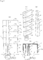
Figure 2 is a set of structural views of a sailing unit of the ocean research ship in accordance with the preferred embodiment of the present invention, in which (a) is a sectional view in the direction of chord length of a hard sail assembly in expanded condition, (b) is a sectional view in the direction of chord length thereof in contracted condition, (c) is a perspective view thereof, and (d) is a perspective view of a mast assembly. -
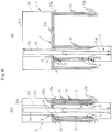
Figure 3 is a set of sectional views showing the contracted condition of the hard sail assembly, the mast assembly and a hydraulic cylinder constituting a sailing unit of the ocean research ship in accordance with the preferred embodiment of the present invention, in which (a) is a sectional view in the direction of chord length showing engaging-disengaging units between the mast sections, (b) is a sectional view in the direction of wing thickness showing engaging-disengaging units between the mast sections and the hydraulic cylinder, (c) is a horizontal sectional view of an engaging-disengaging unit between the mast sections and (d) is a horizontal sectional view of a guide member disposed between the hard sail sections. -
Figure 4 is a set of sectional views showing an intermediate stage of expansion of the hard sail assembly, the mast assembly and the hydraulic cylinder constituting the sailing unit of the ocean research ship in accordance with the preferred embodiment of the present invention, in which (a) is a sectional view in the direction of chord length showing the engaging-disengaging units between the mast sections, (b) is a sectional view in the direction of wing thickness showing the engaging-disengaging units between the mast sections and the hydraulic cylinder. -
Figure 5 is a set of structural views of variations of a mast driving unit. - Preferred embodiments of the present invention will be described.
- As shown in
Figure 1 , a catamaran type ocean research ship A is equipped with apropeller propulsion unit 1 and further with asailing unit 2 having a hard sail. - As shown in
Figure 2 , thesailing unit 2 comprises ahard sail assembly 3, amast assembly 4, ahydraulic cylinder 5 for expanding and contracting themast assembly 4, a motor-gear unit 6 for rotating themast assembly 4 around the longitudinal axis thereof, engaging-disengaging units between mast sections, and engaging-disengaging units between the mast sections and thehydraulic cylinder 5. The engaging-disengaging units between the mast sections and the engaging-disengaging units between the mast sections and thehydraulic cylinder 5 will be described later in detail. - As shown in
Figure 2 , thehard sail assembly 3 comprises fivehard sail sections 31 made of carbon fiber reinforced plastic. The fivehard sail sections 31 are vertically stacked. Eachhard sail section 31 has a symmetrical wing-shaped hollow cross section. Each of the upper fourhard sail sections 31 is telescopically fitted on thehard sail section 31 immediately below. Eachhard sail section 31 is provided with atop plate 31a at the upper end and with aframe 31b at the lower end. Theframe 31b surrounds the outer circumferential surface of thehard sail section 31. - As shown in
Figure 2 , themast assembly 4 comprises fivemast sections 41 made of steel. The fivemast sections 41 are vertically stacked. Eachmast section 41 has a square hollow cross section. Each of the upper fourmast sections 41 is telescopically fitted in themast section 41 immediately below. - The upper ends of the
hard sail sections 31 are connected to the upper ends of themast sections 41 located at the same level by thetop plates 31a. - The upper end of the
uppermost mast section 41 is closed by thetop plate 31a of the uppermosthard sail section 31. The upper end of each of the lower fourmast sections 41 is open. The lower end of thelowermost mast section 41 is closed by abottom plate 41a. The lower end of each of upper fourmast section 41 is open. - The
hydraulic cylinder 5 is disposed in thelowermost mast section 41. Thehydraulic cylinder 5 is mounted on thebottom plate 41a of thelowermost mast section 41 to extend upward. - A
mast base member 7 vertically extends through a deck A' of the ocean research ship A to support thelowermost mast section 41. The motor-gear unit 6 engages themast base member 7. - As shown in
Figure 3 , thehydraulic cylinder 5 comprises acylinder rod 5a swingably supported by thebottom plate 41a of thelowermost mast section 41 and acylinder tube 5b into which the upper portion of thecylinder rod 5a is inserted. - The engaging-disengaging units between mast sections and the engaging-disengaging units between the mast sections and the hydraulic cylinder will be described below. Details of an expansion-contraction unit for the
mast assembly 4 using the engaging-disengaging units between mast sections and the engaging-disengaging units between the mast sections and the hydraulic cylinder as described below are the same as those disclosed in, for example, Japanese Patents Nos.3212467 4263280 - The
cylinder tube 5b is provided with anengaging member 8 horizontally reciprocated by a hydraulic cylinder not shown in the figures and a pair ofpins 9 horizontally reciprocated by another hydraulic cylinder not shown in the figures. Theengaging member 8 and the pair ofpins 9 are distanced from each other by 90 degrees in the circumferential direction. - Each of the upper four
mast sections 41 is provided at a portion near the lower end with apin 10 horizontally and outwardly forced by a spring. - Each of the upper four
mast sections 41 is provided at the portion near the lower end with ahole 11 into which thepin 10 of themast section 41 immediately above can be fitted. Each of the lower fourmast sections 41 is provided at the portion near the upper end with ahole 12 into which thepin 10 of themast section 41 immediately above can be fitted. - Each of the upper four
mast sections 41 is provided at the portion near the lower end with a pair ofholes 13 into which the pair ofpins 9 of thecylinder tube 5b can be fitted. - Operation of the
sailing unit 2 will be described. - When the ocean research ship A does not use the
sailing unit 2, thehydraulic cylinder 5 contracts as shown inFigure 3 . The overlapping lengths between verticallyadjacent mast sections 41 become maximum to contract themast assembly 4, thereby maximizing the overlapping lengths between vertically adjacenthard sail sections 31 to contract thehard sail assembly 3. - The engaging
member 8 of thecylinder tube 5b is projected to an extended position so as to engage thepin 10 of the uppermost mast section 41.The engagingmember 8 engages thepin 10 in the horizontal direction but not in the vertical direction as is clear fromFigure 3(c) . - The pair of
pins 9 of thecylinder tube 5b is projected to an extended position so as to fit in the pair ofholes 13 of theuppermost mast section 41, thereby fixing theuppermost mast section 41 to thecylinder tube 5b. - The
pin 10 of each of the upper fourmast sections 41 is forced by the spring to fit in thehole 11 of themast section 41 immediately below, thereby fixing each of the upper fourmast sections 41 to themast section 41 immediately below. - When the ocean research ship A uses the
sailing unit 2, the engagingmember 8 of thecylinder tube 5b moves against the force of the spring to a retracted position so as to disengage thepin 10 of theuppermost mast section 41 from thehole 11 of themast section 41 immediately below, thereby releasing the fixing of theuppermost mast section 41 to themast section 41 immediately below. - As shown in
Figure 4 , thehydraulic cylinder 5 expands so as to move thecylinder tube 5b upward, thereby moving theuppermost mast section 41 fixed to thecylinder tube 5b upward so as to move upward the uppermosthard sail section 31 connected to theuppermost mast section 41 through thetop plate 31a. - The engaging
member 8 of thecylinder tube 5b moves to the extended position so as to fit thepin 10 of theuppermost mast section 41 in thehole 12 of themast section 41 immediately below, thereby fixing theuppermost mast section 41 to themast section 41 immediately below. - The pair of
pins 9 of thecylinder tube 5b moves to the retracted position so as to be disengaged from the pair ofholes 13 of theuppermost mast section 41, thereby releasing the fixing of theuppermost mast section 41 to thecylinder tube 5b. - The
hydraulic cylinder 5 retracts so as to move thecylinder tube 5b downward. Thepin 10 of theuppermost mast section 41 remains fitted in thehole 12 of themast section 41 immediately below under the biasing force of the spring so as to maintain the fixing of theuppermost mast section 41 to themast section 41 immediately below. The engagingmember 8 located at the extended position, which engages thepin 10 in the horizontal direction but not in the vertical direction, is disengaged from thepin 10 of theuppermost mast section 41 as thecylinder tube 5b moves downward. Therefore, thecylinder tube 5b can smoothly move downward. - When the engaging
member 8 located at the extended position engages thepin 10 of themast section 41 next to theuppermost mast section 41, thecylinder tube 5b stops. - The engaging
member 8 moves against the biasing force of the spring to the retracted position so as to disengage thepin 10 of themast section 41 next to theuppermost mast section 41 from thehole 11 of themast section 41 immediately below, thereby releasing the fixing of themast section 41 next to theuppermost mast section 41 to themast section 41 immediately below. - The pair of
pins 9 of thecylinder tube 5b move to the extended positions so as to fit in the pair ofholes 13 of themast section 41 next to theuppermost mast section 41, thereby fixing themast section 41 next to theuppermost mast section 41 to thecylinder tube 5b. - The
hydraulic cylinder 5 expands so as to move thecylinder tube 5b upward, thereby moving upward themast section 41 next to theuppermost mast section 41 which is fixed to thecylinder tube 5b so as to move upward thehard sail section 31 next to the uppermosthard sail section 31 which is connected to themast section 41 next to theuppermost mast section 41 through thetop plate 31a. - The engaging
member 8 of thecylinder tube 5 moves to the extended position so as to fit thepin 10 of themast section 41 next to theuppermost mast section 41 in thehole 12 of themast section 41 immediately below, thereby fixing themast section 41 next to theuppermost mast section 41 to themast section 41 immediately below. - The pair of
pins 9 of thecylinder tube 5b move to the retracted position so as to disengage from the pair ofholes 13 of themast section 41 next to theuppermost mast section 41, thereby releasing the fixing of themast section 41 next to theuppermost mast section 41 to thecylinder tube 5. - The
hydraulic cylinder 5 retracts so as to move thecylinder tube 5b downward. - When the engaging
member 8 located at the extended position engages thepin 10 of themast section 41 immediately below themast section 41 next to theuppermost mast section 41, thecylinder tube 5b stops. - The aforementioned operations are repeated so as to reduce the overlapping lengths between vertically
adjacent mast sections 41 constituting themast assembly 4 to the minimum level, thereby reducing the overlapping lengths between vertically adjacenthard sail sections 31 constituting thehard sail assembly 3 to the minimum level so as to telescopically expand thehard sail assembly 3. - The motor-
gear unit 6 operates so as to rotate themast base member 7 around the vertically extending central axis, thereby rotating themast assembly 4 around the longitudinal axis thereof so as to direct thehard sail assembly 3 in the optimum direction relative to the wind. - The catamaran type ocean research ship A navigates using the thrust of the
propeller propulsion unit 1 plus the additional thrust generated by thehard sail assembly 3 of thesailing unit 2. - When the expanded
mast assembly 3 is retracted, the aforementioned operations are reversed. That is, each of the upper fourmast sections 41 is moved downward toward themast section 41 immediately below so as to maximize the overlapping lengths between verticallyadjacent mast sections 41 constituting themast assembly 4, thereby maximizing the overlapping lengths between vertically adjacenthard sail sections 31 constituting thehard sail assembly 3. - In the ocean research ship A, the
hard sail assembly 3 comprises a plurality ofhard sail sections 31 of wing-shaped hollow cross section vertically stacked and can expand and contract so as to change its height. Therefore, the height of thehard sail assembly 3 can be adjusted so as not to obstruct passage of the ship under bridges. - In the ocean research ship A, chord length of the
hard sail assembly 3 in expanded condition increases from the lower portion to the higher portion as is clear fromFigure 2(a) because the eachhard sail section 31 except the lowermost fits on thehard sail section 31 immediately below. On the other hand, wing velocity increases as the height from the deck A' of the ocean research ship A increases. Therefore, thehard sail assembly 3 of the ocean research ship A can efficiently catch the wind force. - In the ocean research ship A, the upper ends of the
hard sail sections 31 are connected to the upper ends of themast sections 41 located at the same level so that thehard sail sections 31 are supported by themast sections 41 located at the same level. Therefore, thesailing unit 2 can be made lightweight and imparted with appropriate strength by making thehard sail sections 31, which are large sized, of lightweight resin and making themast sections 41, which are small sized compared to thehard sail sections 31, of high strength material such as steel or the like. - The
top plates 31a provided on the upper ends of thehard sail sections 31 and theframes 31b provided on the lower ends of thehard sail sections 31 effectively operate as members for maintaining the wing-shaped hollow cross sections of thehard sail sections 31. No other member need be disposed at the upper ends of thehard sail sections 31 so as to maintain the wing-shaped hollow cross section because thetop plates 31a for connecting the upper ends of thehard sail sections 31 to the upper ends of themast sections 41 are used as the members for maintaining the wing-shaped hollow cross sections at the upper ends of thehard sail sections 31. Thus, the number of members constituting thehard sail assembly 3 can be reduced. Theframes 31b surrounding the outer circumferential surfaces of thehard sail sections 31, which are the members for maintaining the wing-shaped hollow cross sections at the lower ends of thehard sail sections 31, are advantageous in that they do not obstruct the expansion and contraction of thehard sail assembly 3. - As shown in
Figure 3(d) , it is possible to fix a plurality of rails 14a circumferentially distanced from each other and extending vertically on the inner surface of each of the upper fourhard sail sections 31, and a plurality ofcarriages 14b circumferentially distanced from each other on the upper portion of the outer surface of each of the lower fourhard sail sections 31, and engage the rails 14a of each of the upper fourhard sail sections 31 with thecarriages 14b of thehard sail section 31 immediately blow through ball bearings 14c.Guide members 14 formed by the rails 14a, thecarriages 14b and the ball bearings 14c guide vertically eachhard sail section 31 except the lowermost relative to thehard sail section 31 immediately below. Therefore, expansion and contraction movement of thehard sail assembly 3 can be made smooth. Other guide member configurations are also possible. - As shown in
Figure 5(a) , the inner surface of the lower end of each of the lower fourmast sections 41 can be connected to the outer surface of the upper end of themast section 41 immediately above through ahydraulic jack 15 so as to expand and contract themast assembly 4 by driving fourhydraulic jacks 15. - As shown in
Figure 5(b) , the inner surface of the each of the lower fourmast sections 41 can be connected to the outer surface of themast section 41 immediately above through a rack-and-pinion 16 so as to expand and contract themast assembly 4 by driving motors provided for thepinions 16. - As shown in
Figure 5(c) , a hoist 17 can be disposed between each of the lower fourmast sections 41 and the mast section 41immediately above so as to expand and contract themast assembly 4 by driving fourhoists 17. - As shown in
Figure 5(d) , apantograph 18 and ahydraulic jack 19 for driving thepantograph 18 up and down can be disposed between thetop plate 31a of each of the lower fourhard sail sections 31 and that of thehard sail section 31 immediately above so as to expand and contract themast assembly 4 by driving fourhydraulic jacks 19. - The
mast assembly 4 can be expanded and contracted by driving units other than aforementioned ones. Any driving unit can be used insofar as it can expand and contract themast assembly 4 and keep themast assembly 4 at the expanded position. - The motor-gear unit is not restricted to the one shown in
Figure 2 . Any motor-gear unit can be used insofar as it can rotate themast base member 7 around the vertically extending central axis, thereby rotating themast assembly 4 around the longitudinal axis thereof so as to direct thehard sail assembly 3 in the optimum direction relative to the wind. - The
sailing unit 2 can be installed on various kinds of commercial ships, passenger ships, etc.
Claims (3)
- A sailing ship comprising:a sailing unit (2) which comprises a hard sail assembly (3) comprising a plurality of hard sail sections (31) of wing-shaped hollow cross section vertically stacked so that each except the lowermost fits on the one immediately below,a mast assembly (4) comprising a plurality of mast sections (41) of hollow cross section vertically stacked so that each except the lowermost fits in the one immediately below,connecting members (31a) for connecting the upper ends of the hard sail sections (31) to the upper ends of the mast sections (41) located at the same level,first means (5) for moving each mast section (41) except the lowermost toward and away from the one immediately below, andsecond means (6) for rotating the mast assembly (4) around its longitudinal axis,wherein overlapping lengths between vertically adjacent mast sections (41) are variably controlled to variably control overlapping lengths between vertically adjacent hard sail sections (31), thereby vertically expanding and contracting the hard sail assembly (3).
- A sailing ship of claim 1, wherein each hard sail section (31) is provided with members for maintaining the wing-shaped hollow cross section at the upper end and the lower end,
the member at the upper end is the connecting member (31 a) for connecting the upper end of the hard sail section (31) to the upper end of the mast section (41) located at the same level, and
the member at the lower end is a frame (31 b) surrounding the outer circumferential surface of the hard sail section (31). - A sailing ship of claim 1 or 2, wherein the sailing unit (2) further comprises means for vertically guiding each hard sail section (31) except the lowermost relatively to the hard sail section (31) immediately below.
Applications Claiming Priority (1)
| Application Number | Priority Date | Filing Date | Title |
|---|---|---|---|
| JP2010065143A JP5318008B2 (en) | 2010-03-19 | 2010-03-19 | Sailing ship |
Publications (3)
| Publication Number | Publication Date |
|---|---|
| EP2366621A2 EP2366621A2 (en) | 2011-09-21 |
| EP2366621A3 EP2366621A3 (en) | 2014-06-18 |
| EP2366621B1 true EP2366621B1 (en) | 2017-01-25 |
Family
ID=44235953
Family Applications (1)
| Application Number | Title | Priority Date | Filing Date |
|---|---|---|---|
| EP11157174.1A Active EP2366621B1 (en) | 2010-03-19 | 2011-03-07 | Sailing Ship |
Country Status (5)
| Country | Link |
|---|---|
| US (1) | US8413598B2 (en) |
| EP (1) | EP2366621B1 (en) |
| JP (1) | JP5318008B2 (en) |
| KR (1) | KR20110105727A (en) |
| CN (1) | CN102190078A (en) |
Families Citing this family (27)
| Publication number | Priority date | Publication date | Assignee | Title |
|---|---|---|---|---|
| ES2983067T3 (en) * | 2011-03-21 | 2024-10-21 | Engineered Controls Int Llc | Quick connect coupler with evacuation stop |
| CN102407928B (en) * | 2011-10-24 | 2014-08-13 | 重庆长航东风船舶工业公司 | Hydraulic lift chimney for ship |
| CN113232818A (en) * | 2012-06-29 | 2021-08-10 | 帆船技术有限公司 | Wing type sail |
| AU2013351956B2 (en) * | 2012-11-28 | 2017-11-02 | Robert Reginald BRAY | Wing and application thereof |
| USD720280S1 (en) * | 2013-05-06 | 2014-12-30 | Robert Reginald Bray | Wingsail |
| CN103253351B (en) * | 2013-05-14 | 2015-12-02 | 上海珐伊玻璃钢船艇有限公司 | Sailing boat |
| CN103538710B (en) * | 2013-11-04 | 2015-09-30 | 上海海事大学 | A kind of adjustable for height segment type sail |
| JP6439260B2 (en) * | 2014-03-18 | 2018-12-19 | 株式会社タダノ | Telescopic hard sail control method and control device for hard sail ship |
| JP2015205525A (en) * | 2014-04-17 | 2015-11-19 | 株式会社タダノ | Hard sail ship |
| CN104118551B (en) * | 2014-08-11 | 2017-02-15 | 中国船舶重工集团公司第七○二研究所 | Automatic retractable type combined wind blade device |
| JP6373156B2 (en) * | 2014-10-14 | 2018-08-15 | 株式会社大内海洋コンサルタント | Container side windshield device and side windshield method for container ship |
| CN104890845B (en) * | 2015-06-23 | 2017-04-05 | 江苏科技大学 | Horizontal foldable automatic deploying and retracting aerofoil profile sail |
| CN104973217A (en) * | 2015-07-20 | 2015-10-14 | 中国船舶重工集团公司第七○二研究所 | Layout structure of upper-layer construction of sailboat |
| ES2557518B1 (en) * | 2015-08-24 | 2016-10-19 | Andrés CHACON FIDALGO | Lifting and lowering system for wing sails and corresponding sails |
| CN105539795A (en) * | 2015-12-21 | 2016-05-04 | 中国船舶重工集团公司第七○二研究所 | Sailing boat with layered adjustable hard sail surfaces |
| FR3058386B1 (en) * | 2016-11-08 | 2019-06-28 | Ayro | VELIC PROPULSION SHIP. |
| WO2020115717A1 (en) | 2018-12-06 | 2020-06-11 | Ayro | Ship with sail propulsion |
| CN107878720B (en) * | 2017-11-09 | 2019-06-04 | 沈阳工程学院 | A retractable symmetrical airfoil sail device |
| CN111727152B (en) * | 2018-02-02 | 2023-02-17 | M·弗雷泽 | Sail |
| DE202019102941U1 (en) | 2019-02-18 | 2019-06-05 | Becker Marine Systems Gmbh | Fixed sails for watercraft, in particular for large ships, and watercraft with rigid sails |
| KR102596174B1 (en) * | 2019-09-23 | 2023-10-30 | 삼성중공업 주식회사 | Apparatus for propulsion |
| CN112027043B (en) * | 2020-08-24 | 2024-06-28 | 上海工程技术大学 | Hydraulic cylinder sail driving device and coordination control method |
| DE102021213123A1 (en) | 2021-10-08 | 2023-04-13 | Detlev Löll & Uwe Reum Wingsails GbR (Dipl.-Ing. Uwe Reum, 99817 Eisenach) | Wing sail, watercraft and method of operating a wing sail |
| CN115027653A (en) * | 2022-07-15 | 2022-09-09 | 上海外高桥造船有限公司 | A lift-type wind-powered navigation aid device and a ship |
| CN115610632A (en) * | 2022-10-28 | 2023-01-17 | 大连船舶重工集团有限公司 | A liftable sail with a ball sliding mechanism |
| CN115783121A (en) * | 2022-10-28 | 2023-03-14 | 大连船舶重工集团有限公司 | Liftable sail with double-layer polygonal mast structure |
| FR3159791A1 (en) * | 2024-02-29 | 2025-09-05 | Aeroforce | telescopic mast for sail-powered vessel |
Family Cites Families (16)
| Publication number | Priority date | Publication date | Assignee | Title |
|---|---|---|---|---|
| JPS57198195A (en) * | 1981-05-28 | 1982-12-04 | Nippon Kokan Kk <Nkk> | Marine canvas rig |
| JPS57198194A (en) * | 1981-05-28 | 1982-12-04 | Nippon Kokan Kk <Nkk> | Furling and unfurling system for marine canvas |
| JPS5828098U (en) * | 1981-08-17 | 1983-02-23 | 日立造船株式会社 | sailing ship |
| JPS61200091A (en) * | 1985-02-28 | 1986-09-04 | Osaka Sosenjo:Kk | Hard sail device for ship |
| US4685410A (en) * | 1985-04-08 | 1987-08-11 | Fuller Robert R | Wing sail |
| IT1231705B (en) * | 1989-09-15 | 1991-12-20 | Giorgio Magrini | SAIL STRUCTURE SO-CALLED AT WING. |
| JPH03212467A (en) | 1990-01-17 | 1991-09-18 | Toppan Printing Co Ltd | Acrylic coating material and its use |
| JPH04263280A (en) | 1991-02-18 | 1992-09-18 | Canon Inc | Fixing heating device for image forming equipment |
| DE59104424D1 (en) * | 1991-04-29 | 1995-03-09 | Wilhelm Brinkmann | Profile sail. |
| DE4344795A1 (en) * | 1993-12-28 | 1995-06-29 | Liebherr Werk Ehingen | Mobile crane with a telescopic boom |
| US5517940A (en) * | 1995-05-08 | 1996-05-21 | Beyer; Jay R. | Variable width multi-hulled boat with telescoping mast |
| JP4263280B2 (en) * | 1998-11-24 | 2009-05-13 | 株式会社タダノ | Mobile crane boom telescopic mechanism |
| US6526901B2 (en) * | 2001-03-30 | 2003-03-04 | Camillo M. Iacoboni | Retractable mast for sailboats |
| JP2005280533A (en) | 2004-03-30 | 2005-10-13 | Sumitomo Heavy Industries Marine & Engineering Co Ltd | Sailing Merchant |
| JP2006111026A (en) | 2004-10-12 | 2006-04-27 | Fukushima Zosen Tekkosho:Kk | Telescopic mast device |
| JP5137628B2 (en) * | 2008-03-08 | 2013-02-06 | 株式会社大内海洋コンサルタント | Sailing ship with hard sails |
-
2010
- 2010-03-19 JP JP2010065143A patent/JP5318008B2/en active Active
-
2011
- 2011-03-07 EP EP11157174.1A patent/EP2366621B1/en active Active
- 2011-03-18 CN CN2011100659871A patent/CN102190078A/en active Pending
- 2011-03-18 KR KR1020110024255A patent/KR20110105727A/en not_active Ceased
- 2011-03-18 US US13/051,841 patent/US8413598B2/en active Active
Non-Patent Citations (1)
| Title |
|---|
| None * |
Also Published As
| Publication number | Publication date |
|---|---|
| CN102190078A (en) | 2011-09-21 |
| JP2011195059A (en) | 2011-10-06 |
| KR20110105727A (en) | 2011-09-27 |
| EP2366621A2 (en) | 2011-09-21 |
| JP5318008B2 (en) | 2013-10-16 |
| US8413598B2 (en) | 2013-04-09 |
| EP2366621A3 (en) | 2014-06-18 |
| US20110226172A1 (en) | 2011-09-22 |
Similar Documents
| Publication | Publication Date | Title |
|---|---|---|
| US8413598B2 (en) | Sailing ship | |
| US8117978B2 (en) | Sailing ship equipped with a hard sail | |
| US5314083A (en) | Telescopic tower | |
| CN105366009B (en) | For installing the wind turbine installation ship of offshore wind turbines and using its method | |
| EP2681400B1 (en) | A cantilever system and method of use | |
| KR102944143B1 (en) | Wind-propelled System and Ship having the same | |
| NL2018377B1 (en) | METHOD FOR PLACING A WINDMILL | |
| JP6001750B2 (en) | Ship with side sail formed by hard sail and method for storing and deploying side sail | |
| JP2012240539A (en) | Ship having square sail formed with hard sail, and method for accommodating and deploying square sail | |
| US20180215453A1 (en) | Wing-type sail system | |
| WO2021005420A1 (en) | Telescopic square sail device | |
| JP5865604B2 (en) | Ship with side sail formed by hard sail and method for storing and deploying side sail | |
| CN113404648A (en) | Integral rapid floating installation method for offshore wind turbine | |
| KR102474058B1 (en) | Wind turbine installation vessel | |
| CN117328341B (en) | Urgent repair pier based on scalable pier shaft | |
| KR101475204B1 (en) | Canister-type thruster | |
| KR101487678B1 (en) | Canister-type thruster | |
| SE1001108A1 (en) | Telescopic sailing arrangement | |
| CN120292020A (en) | Tower mounting base and wind turbine equipment | |
| CN121317042A (en) | Floating wind turbine platform and its installation method | |
| EP4705180A1 (en) | Wind or mechanical activated flexible wingsail | |
| KR101475205B1 (en) | Canister-type thruster | |
| CN117719639A (en) | Semi-submersible fan installation platform and fan installation method | |
| KR101475198B1 (en) | Canister-type thruster and control method thereof | |
| JP4242312B2 (en) | Dodger structure |
Legal Events
| Date | Code | Title | Description |
|---|---|---|---|
| PUAI | Public reference made under article 153(3) epc to a published international application that has entered the european phase |
Free format text: ORIGINAL CODE: 0009012 |
|
| 17P | Request for examination filed |
Effective date: 20110307 |
|
| AK | Designated contracting states |
Kind code of ref document: A2 Designated state(s): AL AT BE BG CH CY CZ DE DK EE ES FI FR GB GR HR HU IE IS IT LI LT LU LV MC MK MT NL NO PL PT RO RS SE SI SK SM TR |
|
| AX | Request for extension of the european patent |
Extension state: BA ME |
|
| PUAL | Search report despatched |
Free format text: ORIGINAL CODE: 0009013 |
|
| AK | Designated contracting states |
Kind code of ref document: A3 Designated state(s): AL AT BE BG CH CY CZ DE DK EE ES FI FR GB GR HR HU IE IS IT LI LT LU LV MC MK MT NL NO PL PT RO RS SE SI SK SM TR |
|
| AX | Request for extension of the european patent |
Extension state: BA ME |
|
| RIC1 | Information provided on ipc code assigned before grant |
Ipc: B63H 9/06 20060101AFI20140512BHEP Ipc: B63H 9/08 20060101ALI20140512BHEP |
|
| GRAP | Despatch of communication of intention to grant a patent |
Free format text: ORIGINAL CODE: EPIDOSNIGR1 |
|
| INTG | Intention to grant announced |
Effective date: 20160902 |
|
| STAA | Information on the status of an ep patent application or granted ep patent |
Free format text: STATUS: GRANT OF PATENT IS INTENDED |
|
| GRAS | Grant fee paid |
Free format text: ORIGINAL CODE: EPIDOSNIGR3 |
|
| GRAA | (expected) grant |
Free format text: ORIGINAL CODE: 0009210 |
|
| STAA | Information on the status of an ep patent application or granted ep patent |
Free format text: STATUS: THE PATENT HAS BEEN GRANTED |
|
| AK | Designated contracting states |
Kind code of ref document: B1 Designated state(s): AL AT BE BG CH CY CZ DE DK EE ES FI FR GB GR HR HU IE IS IT LI LT LU LV MC MK MT NL NO PL PT RO RS SE SI SK SM TR |
|
| REG | Reference to a national code |
Ref country code: GB Ref legal event code: FG4D |
|
| REG | Reference to a national code |
Ref country code: CH Ref legal event code: EP |
|
| REG | Reference to a national code |
Ref country code: AT Ref legal event code: REF Ref document number: 863936 Country of ref document: AT Kind code of ref document: T Effective date: 20170215 |
|
| REG | Reference to a national code |
Ref country code: IE Ref legal event code: FG4D |
|
| REG | Reference to a national code |
Ref country code: DE Ref legal event code: R096 Ref document number: 602011034590 Country of ref document: DE |
|
| REG | Reference to a national code |
Ref country code: FR Ref legal event code: PLFP Year of fee payment: 7 |
|
| REG | Reference to a national code |
Ref country code: LT Ref legal event code: MG4D |
|
| REG | Reference to a national code |
Ref country code: NL Ref legal event code: MP Effective date: 20170125 |
|
| REG | Reference to a national code |
Ref country code: AT Ref legal event code: MK05 Ref document number: 863936 Country of ref document: AT Kind code of ref document: T Effective date: 20170125 |
|
| PG25 | Lapsed in a contracting state [announced via postgrant information from national office to epo] |
Ref country code: NL Free format text: LAPSE BECAUSE OF FAILURE TO SUBMIT A TRANSLATION OF THE DESCRIPTION OR TO PAY THE FEE WITHIN THE PRESCRIBED TIME-LIMIT Effective date: 20170125 |
|
| PG25 | Lapsed in a contracting state [announced via postgrant information from national office to epo] |
Ref country code: NO Free format text: LAPSE BECAUSE OF FAILURE TO SUBMIT A TRANSLATION OF THE DESCRIPTION OR TO PAY THE FEE WITHIN THE PRESCRIBED TIME-LIMIT Effective date: 20170425 Ref country code: HR Free format text: LAPSE BECAUSE OF FAILURE TO SUBMIT A TRANSLATION OF THE DESCRIPTION OR TO PAY THE FEE WITHIN THE PRESCRIBED TIME-LIMIT Effective date: 20170125 Ref country code: IS Free format text: LAPSE BECAUSE OF FAILURE TO SUBMIT A TRANSLATION OF THE DESCRIPTION OR TO PAY THE FEE WITHIN THE PRESCRIBED TIME-LIMIT Effective date: 20170525 Ref country code: LT Free format text: LAPSE BECAUSE OF FAILURE TO SUBMIT A TRANSLATION OF THE DESCRIPTION OR TO PAY THE FEE WITHIN THE PRESCRIBED TIME-LIMIT Effective date: 20170125 Ref country code: FI Free format text: LAPSE BECAUSE OF FAILURE TO SUBMIT A TRANSLATION OF THE DESCRIPTION OR TO PAY THE FEE WITHIN THE PRESCRIBED TIME-LIMIT Effective date: 20170125 Ref country code: GR Free format text: LAPSE BECAUSE OF FAILURE TO SUBMIT A TRANSLATION OF THE DESCRIPTION OR TO PAY THE FEE WITHIN THE PRESCRIBED TIME-LIMIT Effective date: 20170426 |
|
| PG25 | Lapsed in a contracting state [announced via postgrant information from national office to epo] |
Ref country code: BG Free format text: LAPSE BECAUSE OF FAILURE TO SUBMIT A TRANSLATION OF THE DESCRIPTION OR TO PAY THE FEE WITHIN THE PRESCRIBED TIME-LIMIT Effective date: 20170425 Ref country code: PL Free format text: LAPSE BECAUSE OF FAILURE TO SUBMIT A TRANSLATION OF THE DESCRIPTION OR TO PAY THE FEE WITHIN THE PRESCRIBED TIME-LIMIT Effective date: 20170125 Ref country code: AT Free format text: LAPSE BECAUSE OF FAILURE TO SUBMIT A TRANSLATION OF THE DESCRIPTION OR TO PAY THE FEE WITHIN THE PRESCRIBED TIME-LIMIT Effective date: 20170125 Ref country code: PT Free format text: LAPSE BECAUSE OF FAILURE TO SUBMIT A TRANSLATION OF THE DESCRIPTION OR TO PAY THE FEE WITHIN THE PRESCRIBED TIME-LIMIT Effective date: 20170525 Ref country code: LV Free format text: LAPSE BECAUSE OF FAILURE TO SUBMIT A TRANSLATION OF THE DESCRIPTION OR TO PAY THE FEE WITHIN THE PRESCRIBED TIME-LIMIT Effective date: 20170125 Ref country code: ES Free format text: LAPSE BECAUSE OF FAILURE TO SUBMIT A TRANSLATION OF THE DESCRIPTION OR TO PAY THE FEE WITHIN THE PRESCRIBED TIME-LIMIT Effective date: 20170125 Ref country code: RS Free format text: LAPSE BECAUSE OF FAILURE TO SUBMIT A TRANSLATION OF THE DESCRIPTION OR TO PAY THE FEE WITHIN THE PRESCRIBED TIME-LIMIT Effective date: 20170125 Ref country code: SE Free format text: LAPSE BECAUSE OF FAILURE TO SUBMIT A TRANSLATION OF THE DESCRIPTION OR TO PAY THE FEE WITHIN THE PRESCRIBED TIME-LIMIT Effective date: 20170125 |
|
| REG | Reference to a national code |
Ref country code: DE Ref legal event code: R097 Ref document number: 602011034590 Country of ref document: DE |
|
| PG25 | Lapsed in a contracting state [announced via postgrant information from national office to epo] |
Ref country code: CZ Free format text: LAPSE BECAUSE OF FAILURE TO SUBMIT A TRANSLATION OF THE DESCRIPTION OR TO PAY THE FEE WITHIN THE PRESCRIBED TIME-LIMIT Effective date: 20170125 Ref country code: EE Free format text: LAPSE BECAUSE OF FAILURE TO SUBMIT A TRANSLATION OF THE DESCRIPTION OR TO PAY THE FEE WITHIN THE PRESCRIBED TIME-LIMIT Effective date: 20170125 Ref country code: SK Free format text: LAPSE BECAUSE OF FAILURE TO SUBMIT A TRANSLATION OF THE DESCRIPTION OR TO PAY THE FEE WITHIN THE PRESCRIBED TIME-LIMIT Effective date: 20170125 Ref country code: IT Free format text: LAPSE BECAUSE OF FAILURE TO SUBMIT A TRANSLATION OF THE DESCRIPTION OR TO PAY THE FEE WITHIN THE PRESCRIBED TIME-LIMIT Effective date: 20170125 Ref country code: RO Free format text: LAPSE BECAUSE OF FAILURE TO SUBMIT A TRANSLATION OF THE DESCRIPTION OR TO PAY THE FEE WITHIN THE PRESCRIBED TIME-LIMIT Effective date: 20170125 |
|
| REG | Reference to a national code |
Ref country code: CH Ref legal event code: PL |
|
| PG25 | Lapsed in a contracting state [announced via postgrant information from national office to epo] |
Ref country code: MC Free format text: LAPSE BECAUSE OF FAILURE TO SUBMIT A TRANSLATION OF THE DESCRIPTION OR TO PAY THE FEE WITHIN THE PRESCRIBED TIME-LIMIT Effective date: 20170125 Ref country code: SM Free format text: LAPSE BECAUSE OF FAILURE TO SUBMIT A TRANSLATION OF THE DESCRIPTION OR TO PAY THE FEE WITHIN THE PRESCRIBED TIME-LIMIT Effective date: 20170125 Ref country code: DK Free format text: LAPSE BECAUSE OF FAILURE TO SUBMIT A TRANSLATION OF THE DESCRIPTION OR TO PAY THE FEE WITHIN THE PRESCRIBED TIME-LIMIT Effective date: 20170125 |
|
| PLBE | No opposition filed within time limit |
Free format text: ORIGINAL CODE: 0009261 |
|
| STAA | Information on the status of an ep patent application or granted ep patent |
Free format text: STATUS: NO OPPOSITION FILED WITHIN TIME LIMIT |
|
| REG | Reference to a national code |
Ref country code: IE Ref legal event code: MM4A |
|
| 26N | No opposition filed |
Effective date: 20171026 |
|
| PG25 | Lapsed in a contracting state [announced via postgrant information from national office to epo] |
Ref country code: LU Free format text: LAPSE BECAUSE OF NON-PAYMENT OF DUE FEES Effective date: 20170307 |
|
| PG25 | Lapsed in a contracting state [announced via postgrant information from national office to epo] |
Ref country code: CH Free format text: LAPSE BECAUSE OF NON-PAYMENT OF DUE FEES Effective date: 20170331 Ref country code: LI Free format text: LAPSE BECAUSE OF NON-PAYMENT OF DUE FEES Effective date: 20170331 Ref country code: SI Free format text: LAPSE BECAUSE OF FAILURE TO SUBMIT A TRANSLATION OF THE DESCRIPTION OR TO PAY THE FEE WITHIN THE PRESCRIBED TIME-LIMIT Effective date: 20170125 Ref country code: IE Free format text: LAPSE BECAUSE OF NON-PAYMENT OF DUE FEES Effective date: 20170307 |
|
| REG | Reference to a national code |
Ref country code: BE Ref legal event code: MM Effective date: 20170331 |
|
| REG | Reference to a national code |
Ref country code: FR Ref legal event code: PLFP Year of fee payment: 8 |
|
| PG25 | Lapsed in a contracting state [announced via postgrant information from national office to epo] |
Ref country code: BE Free format text: LAPSE BECAUSE OF NON-PAYMENT OF DUE FEES Effective date: 20170331 |
|
| PG25 | Lapsed in a contracting state [announced via postgrant information from national office to epo] |
Ref country code: MT Free format text: LAPSE BECAUSE OF NON-PAYMENT OF DUE FEES Effective date: 20170307 |
|
| PG25 | Lapsed in a contracting state [announced via postgrant information from national office to epo] |
Ref country code: HU Free format text: LAPSE BECAUSE OF FAILURE TO SUBMIT A TRANSLATION OF THE DESCRIPTION OR TO PAY THE FEE WITHIN THE PRESCRIBED TIME-LIMIT; INVALID AB INITIO Effective date: 20110307 |
|
| PG25 | Lapsed in a contracting state [announced via postgrant information from national office to epo] |
Ref country code: CY Free format text: LAPSE BECAUSE OF NON-PAYMENT OF DUE FEES Effective date: 20170125 |
|
| PG25 | Lapsed in a contracting state [announced via postgrant information from national office to epo] |
Ref country code: MK Free format text: LAPSE BECAUSE OF FAILURE TO SUBMIT A TRANSLATION OF THE DESCRIPTION OR TO PAY THE FEE WITHIN THE PRESCRIBED TIME-LIMIT Effective date: 20170125 |
|
| PG25 | Lapsed in a contracting state [announced via postgrant information from national office to epo] |
Ref country code: TR Free format text: LAPSE BECAUSE OF FAILURE TO SUBMIT A TRANSLATION OF THE DESCRIPTION OR TO PAY THE FEE WITHIN THE PRESCRIBED TIME-LIMIT Effective date: 20170125 |
|
| REG | Reference to a national code |
Ref country code: DE Ref legal event code: R081 Ref document number: 602011034590 Country of ref document: DE Owner name: OSHIMA SHIPBUILDING CO. LTD., JP Free format text: FORMER OWNERS: GH CRAFT LTD., GOTENBA-SHI, SHIZUOKA, JP; OUCHI OCEAN CONSULTANT, INC., NAGANO, JP Ref country code: DE Ref legal event code: R081 Ref document number: 602011034590 Country of ref document: DE Owner name: OUCHI OCEAN CONSULTANT, INC., JP Free format text: FORMER OWNERS: GH CRAFT LTD., GOTENBA-SHI, SHIZUOKA, JP; OUCHI OCEAN CONSULTANT, INC., NAGANO, JP Ref country code: DE Ref legal event code: R081 Ref document number: 602011034590 Country of ref document: DE Owner name: MITSUI O.S.K. LINES, LTD., JP Free format text: FORMER OWNERS: GH CRAFT LTD., GOTENBA-SHI, SHIZUOKA, JP; OUCHI OCEAN CONSULTANT, INC., NAGANO, JP Ref country code: DE Ref legal event code: R082 Ref document number: 602011034590 Country of ref document: DE Representative=s name: GRUENECKER PATENT- UND RECHTSANWAELTE PARTG MB, DE |
|
| REG | Reference to a national code |
Ref country code: GB Ref legal event code: 732E Free format text: REGISTERED BETWEEN 20200625 AND 20200701 |
|
| PG25 | Lapsed in a contracting state [announced via postgrant information from national office to epo] |
Ref country code: AL Free format text: LAPSE BECAUSE OF FAILURE TO SUBMIT A TRANSLATION OF THE DESCRIPTION OR TO PAY THE FEE WITHIN THE PRESCRIBED TIME-LIMIT Effective date: 20170125 |
|
| P01 | Opt-out of the competence of the unified patent court (upc) registered |
Effective date: 20230331 |
|
| REG | Reference to a national code |
Ref country code: DE Ref legal event code: R081 Ref document number: 602011034590 Country of ref document: DE Owner name: MITSUI O.S.K. LINES, LTD., JP Free format text: FORMER OWNERS: MITSUI O.S.K. LINES, LTD., TOKIO/TOKYO, JP; OSHIMA SHIPBUILDING CO. LTD., NAGASAKI, JP; OUCHI OCEAN CONSULTANT, INC., NAGANO, JP Ref country code: DE Ref legal event code: R081 Ref document number: 602011034590 Country of ref document: DE Owner name: OUCHI OCEAN CONSULTANT, INC., JP Free format text: FORMER OWNERS: MITSUI O.S.K. LINES, LTD., TOKIO/TOKYO, JP; OSHIMA SHIPBUILDING CO. LTD., NAGASAKI, JP; OUCHI OCEAN CONSULTANT, INC., NAGANO, JP |
|
| PGFP | Annual fee paid to national office [announced via postgrant information from national office to epo] |
Ref country code: GB Payment date: 20260330 Year of fee payment: 16 |
|
| PGFP | Annual fee paid to national office [announced via postgrant information from national office to epo] |
Ref country code: DE Payment date: 20260326 Year of fee payment: 16 |
|
| PGFP | Annual fee paid to national office [announced via postgrant information from national office to epo] |
Ref country code: FR Payment date: 20260330 Year of fee payment: 16 |