EP2366473A2 - Verfahren und Vorrichtung zur Herstellung einer Riemenscheibe für Kraftfahrzeugsanwendungen - Google Patents
Verfahren und Vorrichtung zur Herstellung einer Riemenscheibe für Kraftfahrzeugsanwendungen Download PDFInfo
- Publication number
- EP2366473A2 EP2366473A2 EP11158575A EP11158575A EP2366473A2 EP 2366473 A2 EP2366473 A2 EP 2366473A2 EP 11158575 A EP11158575 A EP 11158575A EP 11158575 A EP11158575 A EP 11158575A EP 2366473 A2 EP2366473 A2 EP 2366473A2
- Authority
- EP
- European Patent Office
- Prior art keywords
- punch
- annular
- forming cavity
- blank holder
- head portion
- Prior art date
- Legal status (The legal status is an assumption and is not a legal conclusion. Google has not performed a legal analysis and makes no representation as to the accuracy of the status listed.)
- Granted
Links
Images

Classifications
-
- B—PERFORMING OPERATIONS; TRANSPORTING
- B21—MECHANICAL METAL-WORKING WITHOUT ESSENTIALLY REMOVING MATERIAL; PUNCHING METAL
- B21D—WORKING OR PROCESSING OF SHEET METAL OR METAL TUBES, RODS OR PROFILES WITHOUT ESSENTIALLY REMOVING MATERIAL; PUNCHING METAL
- B21D53/00—Making other particular articles
- B21D53/26—Making other particular articles wheels or the like
- B21D53/261—Making other particular articles wheels or the like pulleys
-
- B—PERFORMING OPERATIONS; TRANSPORTING
- B21—MECHANICAL METAL-WORKING WITHOUT ESSENTIALLY REMOVING MATERIAL; PUNCHING METAL
- B21K—MAKING FORGED OR PRESSED METAL PRODUCTS, e.g. HORSE-SHOES, RIVETS, BOLTS OR WHEELS
- B21K1/00—Making machine elements
- B21K1/28—Making machine elements wheels; discs
- B21K1/42—Making machine elements wheels; discs pulleys, e.g. cable pulleys
-
- F—MECHANICAL ENGINEERING; LIGHTING; HEATING; WEAPONS; BLASTING
- F16—ENGINEERING ELEMENTS AND UNITS; GENERAL MEASURES FOR PRODUCING AND MAINTAINING EFFECTIVE FUNCTIONING OF MACHINES OR INSTALLATIONS; THERMAL INSULATION IN GENERAL
- F16H—GEARING
- F16H55/00—Elements with teeth or friction surfaces for conveying motion; Worms, pulleys or sheaves for gearing mechanisms
- F16H55/32—Friction members
- F16H55/36—Pulleys
- F16H55/44—Sheet-metal pulleys
Definitions
- the present invention relates to a method and a device for producing a pulley for motor vehicle applications, in particular a belt tightener for a belt drive unit of a motor vehicle.
- the pulleys of the above-mentioned type are normally formed by two, substantially cylindrical annular walls, concentric to each another and maintained radially spaced by an intermediate annular connection portion substantially extending in direction orthogonal to the annular walls themselves.
- such pulleys have an H section and are currently obtained by means of chip forming processes, e.g. by turning, starting from a full, cylindrical element.
- This type of machining has a number of drawbacks.
- the aforesaid object is reached by the present invention in that it relates to a method and a device for producing a pulley for motor vehicle applications, as defined in claim 1 and in claim 7, respectively.
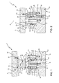
- numerals 1 and 2 indicate respectively two different moulds of the device according to the present invention, which are used in sequence for producing a pulley 3 ( figure 7 ) for motor vehicle applications, in the illustrated case in point a belt tightener for a belt drive of a motor vehicle.
- the mould 1 is used first, and comprises a fixed half mould 4, a mobile half mould 5 facing the fixed half mould 4 and cooperating, in use, with the latter along an axis A, and an actuating assembly (not shown) of the mobile half mould 5 along axis A itself between an opening position ( figure 1 ), in which the mobile half mould 5 is separated from the fixed half mould 4, and a closing position ( figure 2 ), in which the mobile half mould 5 cooperates with the fixed half mould 4.
- the fixed half mould 4 is coaxial to axis A and essentially comprises a base 6 and a die 7, integrally and overhangingly carried by the base 6 and defining a through annular forming cavity 8 of axis A, open both towards the mobile half mould 5 and towards the base 6 itself.
- die 7 is formed by a core 9 and by a tubular element 10, also with axis A, radially more external to core 9 and delimiting the forming cavity 8 therewith.
- Both the core 9 and the tubular element 10 are overhangingly fixed to the base 6 by means of respective screws 11, 12.
- Core 9 is externally delimitated by a substantially cylindrical surface 13 with axis A, and has an end portion 14 manifestly tapered towards the mobile half mould 5 and a concave curvilinear configuration towards the tubular element 10 or, more in general, outwards.
- the tubular element 10 delimits the forming cavity 8 with a radially more internal surface 15 thereof, which has, in sequence starting from the base 6, a first cylindrical segment 16, an annular shoulder 17 facing the base 6 itself, a second substantially cylindrical segment 18 of diameter smaller than that of segment 16, and an end portion 19, facing the end portion 14 of core 9, having a gradually increasing diameter with respect to axis A and a concave curvilinear configuration towards the core 9 itself.
- the core 9 and the tubular element 10 thus mutually define a forming cavity 8, which, in turn, has a first constant section cylindrical portion 20 between the base 6 and the shoulder 17, and a second increasing section portion 21 formed by a first part 22, in which a slight increase of section is found, and a second part 23 manifestly flared towards the mobile half mould 5, having, in section, a receptacle with curvilinear arch profile configuration; it is worth noting that the end portions 14, 19 of the surfaces 13, 15 have a different inclination with respect to axis A, and in particular the end portion 14 has a steeper gradient than the end portion 19.
- both delimiting surfaces 13, 15 of the forming cavity 8 are smooth.
- the fixed half mould 4 further carries a blank holder element 25 with annular configuration, fitted in axially mobile manner along axis A within the forming cavity 8.
- the blank holder element 25 has a cylindrical tubular shape, is provided, at an end thereof arranged on the side of the base 6, with an annular protrusion 26 and ends on the opposite side of a flat head surface 27.
- the blank holder element 25 is elastically loaded by a plurality of helical springs 24 in a first advanced operating position ( figure 1 ), in which it engages an end opening 28 of the forming cavity 8 facing the mobile half mould 5 with the head surface 27 thereof, and may be moved against the bias of the springs 24 to a second retracted operating position ( figure 2 ), in which the head surface 27 thereof is engaged in part 22 of the forming cavity 8 and thus moved away from the end opening 28.
- the protrusion 26 of the blank holder element 25 abuttingly cooperates with shoulder 17, while in the second operating position the aforesaid protrusion 26 is arranged in contact with base 6.
- the springs 24 are accommodated in the respective seats 29 of the base 6 and have a first end cooperating with the bottom (not shown) of the seats 29 themselves and a second end cooperating with the end of the blank holder element 25 carrying the protrusion 26.
- the helical springs 24 may be replaced by gas springs.
- the mobile half mould 5 essentially comprises a supporting wall 30 and a punch 31 with annular configuration, integrally and overhangingly carried by the supporting wall 30, extending coaxially to axis A towards the die 7 of the fixed half mould 4 and adapted to be inserted in the forming cavity 8 pushing the blank holder element 25 into the second operating position against the bias of the springs 24.
- the punch 31 integrally comprises a base flange 32 fixed by means of screws 33 to the supporting wall 30 and a cylindrical tubular engaging body 34, adapted to be inserted in the forming cavity 8 during the approaching movement of the mobile half mould 5 to the fixed half mould 4 along axis A.
- the engaging body 34 of the punch 31 is accommodated in the portion 21 of the forming cavity 8 and cooperates with the product during the step of forming on the opposite part of the blank holder element 25.
- the engaging body 34 of the punch 31 ends axially towards the fixed half mould 4, with an annular head portion 35 having a reduced section with respect to the remaining part of the engaging body 34 itself and tapered towards the free end thereof.
- the head portion 35 is internally and externally delimited by respective truncated-cone-shaped side surfaces 36, 37, mutually converging towards the free end.
- the surfaces 36, 37 originate from different axial zones spaced between one another from the engaging body 34 and thus have different axial heights. More precisely, the origin zone of the internal side surface 36 is arranged farther away from flange 32 than the origin zone of the external side surface 37; in other words, the height of the internal side surface 36 is lower than the axial height of the external side surface 37.
- the diameters side surfaces 36, 37 are increasing towards the free end of the head portion 35 and towards the flange 32, respectively.
- FIGS 3 and 4 show mould 2, which has a structure similar to that of mould 1 and will thus be described hereinafter only by what differs from mould 1 itself, indicating equal or equivalent parts with the same reference numbers followed by prime "'".
- the mould 2 comprises a fixed half mould 4', a mobile half mould 5' and a blank holder element 25' having configurations of entirely similar quality to that of the half moulds 4, 5 and of the blank holder element 25 (which therefore will not be described) but of different sizes.
- the axial size of the forming cavity 8', the blank holder element 25' and the engaging body 34' of the punch 31' of the mobile half mould 5' is larger than that of the corresponding elements of the mould 1.
- pulley 3 is produced by means of two subsequent forming operations carried out on the moulds 1 and 2, respectively.
- the first forming operation is carried out on mould 1 starting from a flat, centrally perforated disc 41; in particular, disc 41 is positioned near the opening of the end 28 of the forming cavity 8, resting it on the flat head surface 27 of the blank holder element 25 maintained in the first operating position thereof by the springs 24.
- the mobile mould 4 is operated making the punch 31 couple with the forming cavity 8.
- the punch 31 presses disc 41 against the head surface 27 of the blank holder element 25 and against the flared end portions 14, 19 of the surfaces 13, 15, which facilitate the U-shaped bending; during the engagement movement thereof in the forming cavity 8, the punch 31 further determines the movement of the blank holder element 25 to the second operating position against the bias of springs 24.
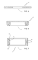
- An annular element 42 shown in detail in figure 6 , having a U-shaped section complementary to the shape of the head portion 35 of the punch 31 is obtained at the end of this first forming operation.
- the annular element 42 is extracted from the mould 1 and inserted in the mould 2.
- the annular element 42 is positioned near the opening of the end 28' of the forming cavity 8', resting it with the hollow part thereof engaging on the head portion 27' complementary to the blank holder element 25' maintained in the first operating position by the springs 24'.
- the mobile half mould 4 is operated making the punch 31' couple with the forming cavity 8'.
- the punch 31' presses the annular element 42 against the head portion 27' of the blank holder element 25' moving the latter to the second operating position against the bias of the springs 24'.
- the element 42 is thus forced to slide between the delimiting surfaces 40' of the forming cavity 8' to obtain, at the end of the stroke of the punch 31', the pulley 3 (shown in greater detail in figure 7 ) having an H section and opposite cavities 45, 46 of shape complementary to the shape of the head portions 27', 35' of the blank holder element 25' and of the punch 31', respectively.
- the pulley 3 is formed by two, substantially cylindrical annular walls 47, 48 concentric to one another and maintained radially spaced by an intermediate, annular connecting portion 50 extending substantially in direction orthogonal to the annular walls 47, 48 themselves and defining the bottom of the opposite cavities 45, 46.
- the axial height of the annular, radially most internal wall 47 of the pulley 3 is smaller than the axial height of the annular, radially most external wall 48.
- the method and the device described allow to obtain the pulley 3 by means of plastic deformation, and thus without wasting material.
- the two forming operations carried out on the moulds 1 and 2 allow to obtain pulleys with particularly thin H section in cost-effective manner and without the risk of breakage.
Landscapes
- Engineering & Computer Science (AREA)
- Mechanical Engineering (AREA)
- General Engineering & Computer Science (AREA)
- Pulleys (AREA)
- Connection Of Motors, Electrical Generators, Mechanical Devices, And The Like (AREA)
Applications Claiming Priority (1)
| Application Number | Priority Date | Filing Date | Title |
|---|---|---|---|
| ITTO2010A000203A IT1399053B1 (it) | 2010-03-16 | 2010-03-16 | Metodo e dispositivo per la realizzazione di una puleggia per applicazioni autoveicolistiche |
Publications (3)
| Publication Number | Publication Date |
|---|---|
| EP2366473A2 true EP2366473A2 (de) | 2011-09-21 |
| EP2366473A3 EP2366473A3 (de) | 2013-01-23 |
| EP2366473B1 EP2366473B1 (de) | 2013-10-09 |
Family
ID=43741128
Family Applications (1)
| Application Number | Title | Priority Date | Filing Date |
|---|---|---|---|
| EP20110158575 Not-in-force EP2366473B1 (de) | 2010-03-16 | 2011-03-16 | Verfahren und Vorrichtung zur Herstellung einer Riemenscheibe für Kraftfahrzeugsanwendungen |
Country Status (2)
| Country | Link |
|---|---|
| EP (1) | EP2366473B1 (de) |
| IT (1) | IT1399053B1 (de) |
Family Cites Families (3)
| Publication number | Priority date | Publication date | Assignee | Title |
|---|---|---|---|---|
| DE19681588T1 (de) * | 1996-08-05 | 1998-08-20 | Kanemitsu Akashi Kk | Verfahren zum Formen eines zylindrischen Bereichs eines zylindrischen Blechteils |
| US20070125147A1 (en) * | 2005-12-06 | 2007-06-07 | Yahya Hodjat | Method of forming a part |
| JP2008264821A (ja) * | 2007-04-19 | 2008-11-06 | Asahi Sangyo Kk | クラッチ用プーリの製造方法 |
-
2010
- 2010-03-16 IT ITTO2010A000203A patent/IT1399053B1/it active
-
2011
- 2011-03-16 EP EP20110158575 patent/EP2366473B1/de not_active Not-in-force
Non-Patent Citations (1)
| Title |
|---|
| None |
Also Published As
| Publication number | Publication date |
|---|---|
| EP2366473B1 (de) | 2013-10-09 |
| ITTO20100203A1 (it) | 2011-09-17 |
| IT1399053B1 (it) | 2013-04-05 |
| EP2366473A3 (de) | 2013-01-23 |
Similar Documents
| Publication | Publication Date | Title |
|---|---|---|
| CN104736269B (zh) | 冲压加工方法及带底容器 | |
| CN110177628B (zh) | 用于制造棱柱形电池单元容器的方法和装置 | |
| KR101547741B1 (ko) | 치형 부품의 제조 방법 및 치형 부품의 제조 장치 | |
| KR101111953B1 (ko) | 증육된 벽 부위를 가진 보스의 성형방법 및 그를 위한 금형장치 | |
| US20150114067A1 (en) | Method for molding pressed component, method for manufacturing pressed component, and die for molding pressed component | |
| US20120266644A1 (en) | Device and method for manufacturing a can body for an aerosol can | |
| JP5692478B1 (ja) | カップ状部材のプレス成形方法 | |
| CN101262965B (zh) | 制造具有侧凹部成型品的方法及用于该方法的锻造成型装置 | |
| KR101461005B1 (ko) | 차량용 변속기의 드럼허브클러치 제조방법 | |
| KR101450779B1 (ko) | 자동차용 풀리 단조 제조 장치 | |
| JP6429095B2 (ja) | 缶端部の被成形部の制御された薄肉化を伴って缶端部を形成するための方法および装置 | |
| EP2366473B1 (de) | Verfahren und Vorrichtung zur Herstellung einer Riemenscheibe für Kraftfahrzeugsanwendungen | |
| KR101528122B1 (ko) | 딥드로잉에 의한 원통형 압력용기 제조 장치 | |
| KR20160128732A (ko) | 요크제조방법 | |
| CN101829719B (zh) | 双金属币/章外环孔壁周向间断凹槽成形装置及方法 | |
| CN106104075A (zh) | 用于无级变速器的传动带的横向段的基础材料及使用该基础材料的冲裁方法 | |
| KR102022835B1 (ko) | 성형재 제조방법 및 그 성형재 | |
| US7191633B1 (en) | Forging apparatus | |
| JP2004322104A (ja) | 絞り成形金型および絞り成形方法 | |
| US20090051089A1 (en) | Damping Element in the Form of a Cylindrical Hollow Body and Method of Production | |
| EP2407258B1 (de) | Verfahren zur Herstellung einer Riemenscheibe für Kraftfahrzeugsanwendungen und dergleichen mit einer Mehrzahl von V-förmigen peripheren Nuten | |
| JP2010131626A (ja) | 円筒歯車の成形方法 | |
| JP4319501B2 (ja) | プーリの製造方法 | |
| US8071213B2 (en) | Resin coated piston manufacturing apparatus for shock absorber | |
| EP2826571B1 (de) | Verfahren zur Herstellung einer Riemenscheibe für Kraftfahrzeuganwendungen |
Legal Events
| Date | Code | Title | Description |
|---|---|---|---|
| PUAI | Public reference made under article 153(3) epc to a published international application that has entered the european phase |
Free format text: ORIGINAL CODE: 0009012 |
|
| AK | Designated contracting states |
Kind code of ref document: A2 Designated state(s): AL AT BE BG CH CY CZ DE DK EE ES FI FR GB GR HR HU IE IS IT LI LT LU LV MC MK MT NL NO PL PT RO RS SE SI SK SM TR |
|
| AX | Request for extension of the european patent |
Extension state: BA ME |
|
| 17P | Request for examination filed |
Effective date: 20111102 |
|
| PUAL | Search report despatched |
Free format text: ORIGINAL CODE: 0009013 |
|
| AK | Designated contracting states |
Kind code of ref document: A3 Designated state(s): AL AT BE BG CH CY CZ DE DK EE ES FI FR GB GR HR HU IE IS IT LI LT LU LV MC MK MT NL NO PL PT RO RS SE SI SK SM TR |
|
| AX | Request for extension of the european patent |
Extension state: BA ME |
|
| RIC1 | Information provided on ipc code assigned before grant |
Ipc: B21H 1/04 20060101ALI20121220BHEP Ipc: B21K 1/42 20060101ALI20121220BHEP Ipc: B21D 53/26 20060101AFI20121220BHEP |
|
| GRAP | Despatch of communication of intention to grant a patent |
Free format text: ORIGINAL CODE: EPIDOSNIGR1 |
|
| RIC1 | Information provided on ipc code assigned before grant |
Ipc: B21K 1/42 20060101ALI20130228BHEP Ipc: B21H 1/04 20060101ALI20130228BHEP Ipc: B21D 53/26 20060101AFI20130228BHEP |
|
| GRAS | Grant fee paid |
Free format text: ORIGINAL CODE: EPIDOSNIGR3 |
|
| GRAA | (expected) grant |
Free format text: ORIGINAL CODE: 0009210 |
|
| AK | Designated contracting states |
Kind code of ref document: B1 Designated state(s): AL AT BE BG CH CY CZ DE DK EE ES FI FR GB GR HR HU IE IS IT LI LT LU LV MC MK MT NL NO PL PT RO RS SE SI SK SM TR |
|
| REG | Reference to a national code |
Ref country code: GB Ref legal event code: FG4D |
|
| REG | Reference to a national code |
Ref country code: AT Ref legal event code: REF Ref document number: 635332 Country of ref document: AT Kind code of ref document: T Effective date: 20131015 Ref country code: CH Ref legal event code: EP |
|
| REG | Reference to a national code |
Ref country code: IE Ref legal event code: FG4D |
|
| REG | Reference to a national code |
Ref country code: DE Ref legal event code: R096 Ref document number: 602011003307 Country of ref document: DE Effective date: 20131205 |
|
| REG | Reference to a national code |
Ref country code: CH Ref legal event code: NV Representative=s name: BOHEST AG, CH |
|
| REG | Reference to a national code |
Ref country code: AT Ref legal event code: MK05 Ref document number: 635332 Country of ref document: AT Kind code of ref document: T Effective date: 20131009 |
|
| REG | Reference to a national code |
Ref country code: NL Ref legal event code: VDEP Effective date: 20131009 |
|
| PG25 | Lapsed in a contracting state [announced via postgrant information from national office to epo] |
Ref country code: SI Free format text: LAPSE BECAUSE OF FAILURE TO SUBMIT A TRANSLATION OF THE DESCRIPTION OR TO PAY THE FEE WITHIN THE PRESCRIBED TIME-LIMIT Effective date: 20131009 |
|
| REG | Reference to a national code |
Ref country code: LT Ref legal event code: MG4D |
|
| REG | Reference to a national code |
Ref country code: DE Ref legal event code: R082 Ref document number: 602011003307 Country of ref document: DE Representative=s name: BOCKHORNI & KOLLEGEN PATENT- UND RECHTSANWAELT, DE Ref country code: DE Ref legal event code: R082 Ref document number: 602011003307 Country of ref document: DE Representative=s name: HEYER, VOLKER, DIPL.-PHYS. DR.RER.NAT., DE |
|
| PG25 | Lapsed in a contracting state [announced via postgrant information from national office to epo] |
Ref country code: SE Free format text: LAPSE BECAUSE OF FAILURE TO SUBMIT A TRANSLATION OF THE DESCRIPTION OR TO PAY THE FEE WITHIN THE PRESCRIBED TIME-LIMIT Effective date: 20131009 Ref country code: NO Free format text: LAPSE BECAUSE OF FAILURE TO SUBMIT A TRANSLATION OF THE DESCRIPTION OR TO PAY THE FEE WITHIN THE PRESCRIBED TIME-LIMIT Effective date: 20140109 Ref country code: BE Free format text: LAPSE BECAUSE OF FAILURE TO SUBMIT A TRANSLATION OF THE DESCRIPTION OR TO PAY THE FEE WITHIN THE PRESCRIBED TIME-LIMIT Effective date: 20131009 Ref country code: IS Free format text: LAPSE BECAUSE OF FAILURE TO SUBMIT A TRANSLATION OF THE DESCRIPTION OR TO PAY THE FEE WITHIN THE PRESCRIBED TIME-LIMIT Effective date: 20140209 Ref country code: HR Free format text: LAPSE BECAUSE OF FAILURE TO SUBMIT A TRANSLATION OF THE DESCRIPTION OR TO PAY THE FEE WITHIN THE PRESCRIBED TIME-LIMIT Effective date: 20131009 Ref country code: LT Free format text: LAPSE BECAUSE OF FAILURE TO SUBMIT A TRANSLATION OF THE DESCRIPTION OR TO PAY THE FEE WITHIN THE PRESCRIBED TIME-LIMIT Effective date: 20131009 Ref country code: FI Free format text: LAPSE BECAUSE OF FAILURE TO SUBMIT A TRANSLATION OF THE DESCRIPTION OR TO PAY THE FEE WITHIN THE PRESCRIBED TIME-LIMIT Effective date: 20131009 Ref country code: NL Free format text: LAPSE BECAUSE OF FAILURE TO SUBMIT A TRANSLATION OF THE DESCRIPTION OR TO PAY THE FEE WITHIN THE PRESCRIBED TIME-LIMIT Effective date: 20131009 |
|
| REG | Reference to a national code |
Ref country code: DE Ref legal event code: R082 Ref document number: 602011003307 Country of ref document: DE Representative=s name: HEYER, VOLKER, DIPL.-PHYS. DR.RER.NAT., DE |
|
| PG25 | Lapsed in a contracting state [announced via postgrant information from national office to epo] |
Ref country code: PL Free format text: LAPSE BECAUSE OF FAILURE TO SUBMIT A TRANSLATION OF THE DESCRIPTION OR TO PAY THE FEE WITHIN THE PRESCRIBED TIME-LIMIT Effective date: 20131009 Ref country code: ES Free format text: LAPSE BECAUSE OF FAILURE TO SUBMIT A TRANSLATION OF THE DESCRIPTION OR TO PAY THE FEE WITHIN THE PRESCRIBED TIME-LIMIT Effective date: 20131009 Ref country code: AT Free format text: LAPSE BECAUSE OF FAILURE TO SUBMIT A TRANSLATION OF THE DESCRIPTION OR TO PAY THE FEE WITHIN THE PRESCRIBED TIME-LIMIT Effective date: 20131009 Ref country code: LV Free format text: LAPSE BECAUSE OF FAILURE TO SUBMIT A TRANSLATION OF THE DESCRIPTION OR TO PAY THE FEE WITHIN THE PRESCRIBED TIME-LIMIT Effective date: 20131009 Ref country code: CY Free format text: LAPSE BECAUSE OF FAILURE TO SUBMIT A TRANSLATION OF THE DESCRIPTION OR TO PAY THE FEE WITHIN THE PRESCRIBED TIME-LIMIT Effective date: 20131009 Ref country code: RS Free format text: LAPSE BECAUSE OF FAILURE TO SUBMIT A TRANSLATION OF THE DESCRIPTION OR TO PAY THE FEE WITHIN THE PRESCRIBED TIME-LIMIT Effective date: 20131009 |
|
| PG25 | Lapsed in a contracting state [announced via postgrant information from national office to epo] |
Ref country code: PT Free format text: LAPSE BECAUSE OF FAILURE TO SUBMIT A TRANSLATION OF THE DESCRIPTION OR TO PAY THE FEE WITHIN THE PRESCRIBED TIME-LIMIT Effective date: 20140210 |
|
| REG | Reference to a national code |
Ref country code: DE Ref legal event code: R097 Ref document number: 602011003307 Country of ref document: DE |
|
| PG25 | Lapsed in a contracting state [announced via postgrant information from national office to epo] |
Ref country code: EE Free format text: LAPSE BECAUSE OF FAILURE TO SUBMIT A TRANSLATION OF THE DESCRIPTION OR TO PAY THE FEE WITHIN THE PRESCRIBED TIME-LIMIT Effective date: 20131009 |
|
| REG | Reference to a national code |
Ref country code: CH Ref legal event code: PCAR Free format text: NEW ADDRESS: HOLBEINSTRASSE 36-38, 4051 BASEL (CH) |
|
| PLBE | No opposition filed within time limit |
Free format text: ORIGINAL CODE: 0009261 |
|
| STAA | Information on the status of an ep patent application or granted ep patent |
Free format text: STATUS: NO OPPOSITION FILED WITHIN TIME LIMIT |
|
| PG25 | Lapsed in a contracting state [announced via postgrant information from national office to epo] |
Ref country code: RO Free format text: LAPSE BECAUSE OF FAILURE TO SUBMIT A TRANSLATION OF THE DESCRIPTION OR TO PAY THE FEE WITHIN THE PRESCRIBED TIME-LIMIT Effective date: 20131009 Ref country code: CZ Free format text: LAPSE BECAUSE OF FAILURE TO SUBMIT A TRANSLATION OF THE DESCRIPTION OR TO PAY THE FEE WITHIN THE PRESCRIBED TIME-LIMIT Effective date: 20131009 Ref country code: SK Free format text: LAPSE BECAUSE OF FAILURE TO SUBMIT A TRANSLATION OF THE DESCRIPTION OR TO PAY THE FEE WITHIN THE PRESCRIBED TIME-LIMIT Effective date: 20131009 Ref country code: IT Free format text: LAPSE BECAUSE OF FAILURE TO SUBMIT A TRANSLATION OF THE DESCRIPTION OR TO PAY THE FEE WITHIN THE PRESCRIBED TIME-LIMIT Effective date: 20131009 |
|
| 26N | No opposition filed |
Effective date: 20140710 |
|
| PG25 | Lapsed in a contracting state [announced via postgrant information from national office to epo] |
Ref country code: DK Free format text: LAPSE BECAUSE OF FAILURE TO SUBMIT A TRANSLATION OF THE DESCRIPTION OR TO PAY THE FEE WITHIN THE PRESCRIBED TIME-LIMIT Effective date: 20131009 |
|
| REG | Reference to a national code |
Ref country code: DE Ref legal event code: R097 Ref document number: 602011003307 Country of ref document: DE Effective date: 20140710 |
|
| PG25 | Lapsed in a contracting state [announced via postgrant information from national office to epo] |
Ref country code: LU Free format text: LAPSE BECAUSE OF FAILURE TO SUBMIT A TRANSLATION OF THE DESCRIPTION OR TO PAY THE FEE WITHIN THE PRESCRIBED TIME-LIMIT Effective date: 20140316 |
|
| REG | Reference to a national code |
Ref country code: FR Ref legal event code: PLFP Year of fee payment: 5 |
|
| REG | Reference to a national code |
Ref country code: FR Ref legal event code: PLFP Year of fee payment: 6 |
|
| PG25 | Lapsed in a contracting state [announced via postgrant information from national office to epo] |
Ref country code: MT Free format text: LAPSE BECAUSE OF FAILURE TO SUBMIT A TRANSLATION OF THE DESCRIPTION OR TO PAY THE FEE WITHIN THE PRESCRIBED TIME-LIMIT Effective date: 20131009 |
|
| PG25 | Lapsed in a contracting state [announced via postgrant information from national office to epo] |
Ref country code: SM Free format text: LAPSE BECAUSE OF FAILURE TO SUBMIT A TRANSLATION OF THE DESCRIPTION OR TO PAY THE FEE WITHIN THE PRESCRIBED TIME-LIMIT Effective date: 20131009 |
|
| PGFP | Annual fee paid to national office [announced via postgrant information from national office to epo] |
Ref country code: IE Payment date: 20160309 Year of fee payment: 6 Ref country code: CH Payment date: 20160311 Year of fee payment: 6 |
|
| PG25 | Lapsed in a contracting state [announced via postgrant information from national office to epo] |
Ref country code: MC Free format text: LAPSE BECAUSE OF FAILURE TO SUBMIT A TRANSLATION OF THE DESCRIPTION OR TO PAY THE FEE WITHIN THE PRESCRIBED TIME-LIMIT Effective date: 20131009 |
|
| PGFP | Annual fee paid to national office [announced via postgrant information from national office to epo] |
Ref country code: GB Payment date: 20160316 Year of fee payment: 6 |
|
| PG25 | Lapsed in a contracting state [announced via postgrant information from national office to epo] |
Ref country code: GR Free format text: LAPSE BECAUSE OF FAILURE TO SUBMIT A TRANSLATION OF THE DESCRIPTION OR TO PAY THE FEE WITHIN THE PRESCRIBED TIME-LIMIT Effective date: 20140110 Ref country code: BG Free format text: LAPSE BECAUSE OF FAILURE TO SUBMIT A TRANSLATION OF THE DESCRIPTION OR TO PAY THE FEE WITHIN THE PRESCRIBED TIME-LIMIT Effective date: 20131009 |
|
| PG25 | Lapsed in a contracting state [announced via postgrant information from national office to epo] |
Ref country code: TR Free format text: LAPSE BECAUSE OF FAILURE TO SUBMIT A TRANSLATION OF THE DESCRIPTION OR TO PAY THE FEE WITHIN THE PRESCRIBED TIME-LIMIT Effective date: 20131009 Ref country code: HU Free format text: LAPSE BECAUSE OF FAILURE TO SUBMIT A TRANSLATION OF THE DESCRIPTION OR TO PAY THE FEE WITHIN THE PRESCRIBED TIME-LIMIT; INVALID AB INITIO Effective date: 20110316 |
|
| REG | Reference to a national code |
Ref country code: FR Ref legal event code: PLFP Year of fee payment: 7 |
|
| REG | Reference to a national code |
Ref country code: CH Ref legal event code: PL |
|
| GBPC | Gb: european patent ceased through non-payment of renewal fee |
Effective date: 20170316 |
|
| REG | Reference to a national code |
Ref country code: IE Ref legal event code: MM4A |
|
| PG25 | Lapsed in a contracting state [announced via postgrant information from national office to epo] |
Ref country code: GB Free format text: LAPSE BECAUSE OF NON-PAYMENT OF DUE FEES Effective date: 20170316 Ref country code: CH Free format text: LAPSE BECAUSE OF NON-PAYMENT OF DUE FEES Effective date: 20170331 Ref country code: LI Free format text: LAPSE BECAUSE OF NON-PAYMENT OF DUE FEES Effective date: 20170331 Ref country code: IE Free format text: LAPSE BECAUSE OF NON-PAYMENT OF DUE FEES Effective date: 20170316 |
|
| REG | Reference to a national code |
Ref country code: FR Ref legal event code: PLFP Year of fee payment: 8 |
|
| PGFP | Annual fee paid to national office [announced via postgrant information from national office to epo] |
Ref country code: FR Payment date: 20180329 Year of fee payment: 8 |
|
| PG25 | Lapsed in a contracting state [announced via postgrant information from national office to epo] |
Ref country code: MK Free format text: LAPSE BECAUSE OF FAILURE TO SUBMIT A TRANSLATION OF THE DESCRIPTION OR TO PAY THE FEE WITHIN THE PRESCRIBED TIME-LIMIT Effective date: 20131009 |
|
| PGFP | Annual fee paid to national office [announced via postgrant information from national office to epo] |
Ref country code: DE Payment date: 20180530 Year of fee payment: 8 |
|
| PG25 | Lapsed in a contracting state [announced via postgrant information from national office to epo] |
Ref country code: AL Free format text: LAPSE BECAUSE OF FAILURE TO SUBMIT A TRANSLATION OF THE DESCRIPTION OR TO PAY THE FEE WITHIN THE PRESCRIBED TIME-LIMIT Effective date: 20131009 |
|
| REG | Reference to a national code |
Ref country code: DE Ref legal event code: R119 Ref document number: 602011003307 Country of ref document: DE |
|
| PG25 | Lapsed in a contracting state [announced via postgrant information from national office to epo] |
Ref country code: DE Free format text: LAPSE BECAUSE OF NON-PAYMENT OF DUE FEES Effective date: 20191001 |
|
| PG25 | Lapsed in a contracting state [announced via postgrant information from national office to epo] |
Ref country code: FR Free format text: LAPSE BECAUSE OF NON-PAYMENT OF DUE FEES Effective date: 20190331 |