EP2366351A1 - System for multi-pole phase-shifted radio frequency application - Google Patents
System for multi-pole phase-shifted radio frequency application Download PDFInfo
- Publication number
- EP2366351A1 EP2366351A1 EP10179305A EP10179305A EP2366351A1 EP 2366351 A1 EP2366351 A1 EP 2366351A1 EP 10179305 A EP10179305 A EP 10179305A EP 10179305 A EP10179305 A EP 10179305A EP 2366351 A1 EP2366351 A1 EP 2366351A1
- Authority
- EP
- European Patent Office
- Prior art keywords
- switching components
- dual
- pole
- electrosurgical generator
- phase
- Prior art date
- Legal status (The legal status is an assumption and is not a legal conclusion. Google has not performed a legal analysis and makes no representation as to the accuracy of the status listed.)
- Granted
Links
Images


Classifications
-
- A—HUMAN NECESSITIES
- A61—MEDICAL OR VETERINARY SCIENCE; HYGIENE
- A61B—DIAGNOSIS; SURGERY; IDENTIFICATION
- A61B18/00—Surgical instruments, devices or methods for transferring non-mechanical forms of energy to or from the body
- A61B18/04—Surgical instruments, devices or methods for transferring non-mechanical forms of energy to or from the body by heating
- A61B18/12—Surgical instruments, devices or methods for transferring non-mechanical forms of energy to or from the body by heating by passing a current through the tissue to be heated, e.g. high-frequency current
- A61B18/1206—Generators therefor
-
- A—HUMAN NECESSITIES
- A61—MEDICAL OR VETERINARY SCIENCE; HYGIENE
- A61B—DIAGNOSIS; SURGERY; IDENTIFICATION
- A61B18/00—Surgical instruments, devices or methods for transferring non-mechanical forms of energy to or from the body
- A61B18/04—Surgical instruments, devices or methods for transferring non-mechanical forms of energy to or from the body by heating
- A61B18/12—Surgical instruments, devices or methods for transferring non-mechanical forms of energy to or from the body by heating by passing a current through the tissue to be heated, e.g. high-frequency current
- A61B18/14—Probes or electrodes therefor
- A61B18/1402—Probes for open surgery
-
- A—HUMAN NECESSITIES
- A61—MEDICAL OR VETERINARY SCIENCE; HYGIENE
- A61B—DIAGNOSIS; SURGERY; IDENTIFICATION
- A61B18/00—Surgical instruments, devices or methods for transferring non-mechanical forms of energy to or from the body
- A61B18/04—Surgical instruments, devices or methods for transferring non-mechanical forms of energy to or from the body by heating
- A61B18/12—Surgical instruments, devices or methods for transferring non-mechanical forms of energy to or from the body by heating by passing a current through the tissue to be heated, e.g. high-frequency current
- A61B18/14—Probes or electrodes therefor
- A61B18/1442—Probes having pivoting end effectors, e.g. forceps
- A61B18/1445—Probes having pivoting end effectors, e.g. forceps at the distal end of a shaft, e.g. forceps or scissors at the end of a rigid rod
-
- A—HUMAN NECESSITIES
- A61—MEDICAL OR VETERINARY SCIENCE; HYGIENE
- A61B—DIAGNOSIS; SURGERY; IDENTIFICATION
- A61B18/00—Surgical instruments, devices or methods for transferring non-mechanical forms of energy to or from the body
- A61B2018/00053—Mechanical features of the instrument of device
- A61B2018/0016—Energy applicators arranged in a two- or three dimensional array
Definitions
- the present disclosure relates to electrosurgical apparatuses, systems and methods. More particularly, the present disclosure is directed to electrosurgical multi-polar electrosurgical systems.
- Energy-based tissue treatment is well known in the art.
- Various types of energy e.g., electrical, ultrasonic, microwave, cryogenic, heat, laser, etc.
- Electrosurgery involves application of high radio frequency electrical current to a surgical site to cut, ablate, coagulate or seal tissue.
- one of the electrodes of the hand-held instrument functions as the active electrode and the other as the return electrode.
- the return electrode is placed in close proximity to the active electrode such that an electrical circuit is formed between the two electrodes (e.g., electrosurgical forceps).
- an electrical circuit is formed between the two electrodes (e.g., electrosurgical forceps).
- the applied electrical current is limited to the body tissue positioned between the electrodes.
- Bipolar electrosurgical techniques and instruments can be used to coagulate blood vessels or tissue, e.g., soft tissue structures, such as lung, brain and intestine.
- a surgeon can either cauterize, coagulate/desiccate and/or simply reduce or slow bleeding, by controlling the intensity, frequency and duration of the electrosurgical energy applied between the electrodes and through the tissue.
- it is necessary to control the output from the electrosurgical generator, e.g., power, waveforms, voltage, current, pulse rate, etc.
- the active electrode In monopolar electrosurgery, the active electrode is typically a part of the surgical instrument held by the surgeon that is applied to the tissue to be treated.
- a patient return electrode is placed remotely from the active electrode to carry the current back to the generator and safely disperse current applied by the active electrode.
- the return electrodes usually have a large patient contact surface area to minimize heating at that site. Heating is caused by high current densities which directly depend on the surface area. A larger surface contact area results in lower localized heat intensity.
- Return electrodes are typically sized based on assumptions of the maximum current utilized during a particular surgical procedure and the duty cycle. In bipolar and monopolar modes, it is desirable to utilize more than one active electrode to achieve desired ablation and lesion formation.
- an electrosurgical generator includes a power supply operable to generate a DC voltage and a multi-pole phase-shifted RF output stage coupled to the power supply.
- the RF output stage includes a plurality of dual-pole circuits, each of the plurality of dual-pole circuits including first and second pairs of switching components.
- the generator also includes a controller configured to drive the first and second pairs of switching components of each of the plurality of dual-pole circuits at a predetermined phase-shifted frequency.
- an electrosurgical system includes an electrosurgical generator having a power supply operable to generate a DC voltage.
- the generator also includes a multi-pole, phase-shifted, pulse-width and/or frequency modulated RF output stage coupled to the power supply.
- the RF output stage includes an isolation transformer having a secondary winding and a plurality of dual-pole circuits having first and second pairs of switching components and a primary winding coupled to the secondary winding.
- the generator further includes a controller configured to drive the first and second pairs of switching components of each of the plurality of dual-pole circuits at a predetermined phase-shifted frequency to generate a waveform crest at each of the output terminals.
- the system also includes a plurality of active electrodes, each of which is coupled to each of the output terminals.
- an electrosurgical system includes an electrosurgical generator having a power supply operable to generate a DC voltage.
- the generator includes a multi-pole, phase-shifted, pulse-width and/or frequency modulated RF output stage coupled to the power supply.
- the RF output stage includes a plurality of dual-pole circuits, each of the plurality of dual-pole circuits including first and second pairs of switching components, the RF output stage further includes an isolation transformer having a secondary winding and wherein each of the plurality of dual-pole circuits includes a primary winding coupled to the secondary winding.
- the generator also includes a controller configured to drive the first and second pairs of switching components of each of the plurality of dual-pole circuit at a predetermined phase-shifted frequency.
- the system includes a plurality of active electrodes, each of which is coupled to each of the output terminals.
- the generator according to the present disclosure can perform monopolar and bipolar electrosurgical procedures, including vessel sealing procedures.
- the generator may include a plurality of outputs for interfacing with various electrosurgical instruments (e.g., a monopolar active electrode, return electrode, bipolar electrosurgical forceps, footswitch, multi-polar ablation needles, etc.).
- various electrosurgical instruments e.g., a monopolar active electrode, return electrode, bipolar electrosurgical forceps, footswitch, multi-polar ablation needles, etc.
- the generator includes electronic circuitry configured for generating radio frequency power specifically suited for various electrosurgical modes (e.g., cutting, blending, division, ablation etc.) and procedures (e.g., monopolar, bipolar, vessel sealing, ablation).
- Fig. 1 is a schematic illustration of a bipolar and monopolar electrosurgical system 1 according to one embodiment of the present disclosure.
- the system 1 includes one or more monopolar electrosurgical instruments 2a. 2b, 2c, etc. having one or more electrodes for treating tissue of a patient (e.g., electrosurgical cutting probe, ablation electrode(s), etc.).
- Electrosurgical RF energy is supplied to the instruments 2a, 2b, 2c by a generator 20 via a corresponding supply line 4a, 4b, 4c, etc., that is connected to an active terminal 30 ( Fig. 2 ) of the generator 20, allowing the instruments 2a, 2b, 2c to coagulate, ablate and/or otherwise treat tissue.
- the energy is returned to the generator 20 through a return electrode 6 via a return line 8 at a return terminal 32 ( Fig. 2 ) of the generator 20.
- the system 1 may include a plurality of return electrodes 6 that are arranged to minimize the chances of tissue damage by maximizing the overall contact area with the patient.
- the generator 20 and the return electrode 6 may be configured for monitoring so-called "tissue-to-patient" contact to insure that sufficient contact exists therebetween to further minimize chances of tissue damage.
- the system 1 also includes a multi-polar ablation device 21 having a plurality of electrodes 23a, 23b, 23c, etc.
- the system 1 also includes a bipolar electrosurgical forceps 10 having one or more pairs of electrodes for treating tissue of a patient.
- the electrosurgical forceps 10 include opposing jaw members 15, 17 having one or more active electrodes 14a, 14b, 14c, etc. and a return electrode 16 disposed therein, respectively.
- the active electrodes 14a, 14b, 14c and the return electrode 16 are connected to the generator 20 through cable 18, which includes the supply and return lines 4, 8 coupled to the active and return terminals 30, 32, respectively.
- the electrosurgical forceps 10 are coupled to the generator 20 at a connector having connections to the active and return terminals 30 and 32 (e.g., pins) via a plug disposed at the end of the cable 18, wherein the plug includes contacts from the supply and return lines 4, 8.
- the generator 20 may be any suitable type (e.g., electrosurgical, microwave, etc.) and may include a plurality of connectors to accommodate various types of electrosurgical instruments (e.g., multiple instruments 2a, 2b, 2c, electrosurgical forceps 10, etc.). Further, the generator 20 is configured to operate in a variety of modes such as ablation, monopolar and bipolar cutting coagulation, etc.
- the generator 20 includes suitable input controls (e.g., buttons, activators, switches, touch screen, etc.) for controlling the generator 20.
- the generator 20 may include one or more display screens (not shown) for providing the user with variety of output information (e.g., intensity settings, treatment complete indicators, etc.).
- the controls allow the user to adjust power of the RF energy, waveform, and other parameters to achieve the desired waveform suitable for a particular task (e.g., coagulating, tissue sealing, ablating, intensity setting, etc.).
- Fig. 2 shows a schematic block diagram of the generator 20 having a controller 24, a high voltage DC power supply 27 ("HVPS”) and an RF output stage 28.
- the HVPS 27 is connected to an AC source (e.g., electrical wall outlet) and provides high voltage DC power to an RF output stage 28, which then converts high voltage DC power into RF energy and delivers the RF energy to the active terminal 30. The energy is returned thereto via the return terminal 32.
- the RF output stage 28 generates sinusoidal or rectangular waveforms of high RF energy.
- the RF output stage 28 is configured to generate a plurality of waveforms having various duty cycles, peak voltages, waveform crest factors, and other suitable parameters. Certain types of waveform are suitable for specific electrosurgical modes.
- the RF output stage 28 typically generates a 100% duty cycle sinusoidal waveforms in cut mode, which is well-suited for ablating, fusing and dissecting tissue and a 1-25% duty cycle waveform in coagulation mode, which is best used for cauterizing tissue to stop bleeding.
- the controller 24 includes a microprocessor 25 operably connected to a memory 26, which may be volatile type memory (e.g., RAM) and/or non-volatile type memory (e.g., flash media, disk media, etc.).
- the microprocessor 25 includes an output port that is operably connected to the HVPS 27 and/or RF output stage 28 allowing the microprocessor 25 to control the output of the generator 20 according to either open and/or closed control loop schemes.
- the microprocessor 25 may be substituted by any logic processor (e.g., control circuit) adapted to perform the calculations discussed herein.
- a closed loop control scheme is a feedback control loop, in which a plurality of sensors measure a variety of tissue and energy properties (e.g., tissue impedance, tissue temperature, output current and/or voltage, etc.), and provide feedback to the controller 24. Such sensors are within the purview of those skilled in the art.
- the controller 24 then signals the HVPS 27 and/or RF output stage 28, which then adjust DC and/or RF output power, respectively.
- the controller 24 also receives input signals from the input controls of the generator 20, the instruments 2a, 2b, 2c or forceps 10.
- the controller 24 utilizes the input signals to adjust power outputted by the generator 20 and/or performs other control functions thereon.
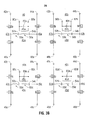
- the RF output stage 28 is a multi-pole, phase-shifted, pulse-width and/or frequency modulated RF inverter as shown in more detail in Figs. 3a and 3B .
- the RF output stage 28 includes two or more dual-pole circuits 40a and 40b (e.g., bridge circuit). Each of the dual-pole circuits 40a and 40b is coupled to the HVPS 27 and receives DC voltage therefrom. More specifically, each of the dual-pole assemblies 40a and 40b includes an isolation transformer 41 a and 41b. respectively. Each of the isolation transformers 41 a and 41 b includes a primary winding 43a, 43b and a secondary winding 45a, 45b, respectively.
- the primary windings 43a and 43b include first and second connections 47a, 49a and 47b, 49b, respectively.
- the first connections 47a, 47b include drain supplies 42a, 42b and source supplies 46a, 46b, respectively.
- the second connections 49a, 49b also include drain supplies 44a, 44b and source supplies 48a, 48b, respectively.
- the source supplies 46a, 48a, 46b, 48b and drain supplies 42a, 44a, 42b, 44b are coupled to the HVPS 27.
- First connection 47a includes a first pair of switching components 56a and 58a and second connection 49a includes a second pair of switching components 60a and 62a, respectively.
- First and second connections 47b and 49b also include first and second pairs of switching components 56b, 58b and 60b, 62b, respectively.
- the switching components 56a, 58a, 60a, 62a and 56b, 58b, 60b, 62b can be, for example, transistors, such as metal-oxide semiconductor field-effect transistors (MOSFET), insulated gate bipolar transistors (IGBT), relays, and the like.
- MOSFET metal-oxide semiconductor field-effect transistors
- IGBT insulated gate bipolar transistors
- the secondary windings 45a, 45b include two output terminals 80a, 82a, 80b, 82b, respectively. Each pair of the output terminals 80a, 82a, 80b, 82b includes a band pass filter 83a and 83b coupled therebetween.
- the first and second connections 47a and 49a are connected in series by a resonant network 50a.
- the resonant network 50a may be a series resonant network that is arranged in an LCC configuration having an inductor 53a and capacitors 52a and 54a with the primary winding 43a being coupled between capacitors 52a and 54a.
- the first and second connections 47b and 49b are similarly connected in series by a resonant network 50b with the primary winding 43b coupled between capacitors 52b and 54b.
- the resonant networks 50a and 50b may be parallel resonant networks and may include a plurality of reactive and passive components.
- Output terminals 80a, 82a and 80b, 82b may be separately connected to multiple active and return pole pairs of monopolar, bipolar electrosurgical or ablation instruments (e.g., instruments 2a, 2b, 2c, electrodes 23a, 23b, 23c or active electrodes 14a, 14b, 14c). Additionally or alternatively, output terminals 80a, 82a and 80b, 82b may share connections to a single active or return lead. In one embodiment, output terminals 82a and 82b are coupled to the return electrode 6, while output terminals 80a and 80b are coupled to active leads on either a single or multiple instruments. This configuration allows for simultaneous activation of instruments or multi-pole pairs of the same instrument (e.g., device 21).
- the RF output stage 28 includes four dual-pole circuits 40a, 40b, 40c and 40d.
- Each of the dual-pole circuits 40c and 40d is substantially similar to the dual-pole circuits 40a and 40b and is also coupled to the HVPS 27 and receives DC voltage therefrom.
- Each of the dual-pole circuits 40c and 40d includes an isolation transformer 41c and 41d, respectively.
- Each of the isolation transformers 41c and 41d includes a primary winding 43c, 43d and a secondary winding 45c, 45d.
- the primary windings 43c and 43d include first and second connections 47c, 49c and 47d, 49b, respectively.
- the first connections 47c, 47d include drain supplies 42c, 42d and source supplies 46d, 46c, respectively.
- the second connections 49c, 49d also includes a drain supply 44c, 44d and source supplies 48c, 48d, respectively.
- the source supplies 46c, 48c, 46d, 48d and drain supplies 42c, 44c, 42d, 44d are coupled to the HVPS 27.
- the first connection 47c includes a first pair of switching components 56c and 58c and the second connection 49c includes a second pair of switching components 60c and 62c, respectively.
- the first and second connections 47d and 49d also include first and second pairs of switching components 56d, 58b and 60d, 62d, respectively.
- the switching components 56c, 58c, 60c, 62c and 56d, 58b, 60d, 62d can be, for example, transistors, such as metal-oxide semiconductor field-effect transistors (MOSFET), insulated gate bipolar transistors (IGBT), relays, and the like.
- MOSFET metal-oxide semiconductor field-effect transistors
- IGBT insulated gate bipolar transistors
- the secondary windings 45c, 45d include two output terminals 80c, 82c, 80d, 82d, respectively. Each pair of the output terminals 80c, 82c, 80d, 82d includes a band pass filter 83c and 83d coupled therebetween.
- the first and second connections 47c and 49c are connected in series by a resonant network 50c having an inductor 53c and capacitors 52c and 54c arranged in a LCC configuration with the primary winding 43c.
- the first and second connections 47d and 49d are similarly connected in series by a resonant network 50d having an inductor 53d with the primary winding 43d coupled between capacitors 52b and 54b.
- the resonant networks 50c and 50d may be parallel resonant networks and may include a plurality of reactive and passive components.
- the operation of the RF output stage 28 is described with respect to Fig. 3A since the operation of four dual-pole circuits 40a, 40b, 40c, 40d of Fig. 3B is substantially similar to that of two dual-pole circuits 40a and 40b.
- the switching components 56a, 58a, 60a, 62a, 56b, 58b, 60b, 62b are coupled to the controller 24.
- the controller 24 drives the switching components 56a, 58a, 60a, 62a, 56b, 58b, 60b, 62b at a predetermined frequency or frequencies to turn “on” and “off' at a range of predetermined frequencies which is also the operating frequency range of the generator 20, thereby closing and opening the first and second connections 47a, 47b and 49a, 49b, respectively.
- the frequency at which the switching components 56a, 58a, 60a, 62a, 56b, 58b, 60b, 62b are turned on and off is controlled by the controller 24.
- the controller 24 may include a pulse-width modulated driver for supplying a driver signal to each of the switching components 56a, 58a, 60a, 62a, 56b, 58b, 60b, 62b.
- the driver emits a phase-shifted drive signals having first and second components that are out of phase (e.g., 180° out-of-phase).
- each pair of the switching components e.g., 56a and 58a, 60a and 62a, 56b and 58b, 60b and 62b
- each pair of the switching components has a phase relationship 180° out-of-phase with its opposing pair.
- the driver signal cycles each of the pairs of the switching components 56a, 58a, 60a, 62a, 56b, 58b, 60b, 62b between "on” and “off' positions at the same frequency but out of sync, to create two waveforms 180° out-of-phase at each first and second connections 47a, 49a, 47b, 49b.
- the drive signals to each pair of the switching components 56a, 58a, 60a, 62a, 56b, 58b, 60b, 62b are also phase-shifted with respect to each other to generate a plurality of waveforms of varying duty cycle. Therefore, adjusting the phase-shifted dual drive signals provides varying operating RF duty cycles or pulse-widths.
- Varying the duty cycle of the phase-shifted dual drive signals allows for better control of the RF amplitude and the average power delivered. Phase-shifting also allows for interleaving of power delivered to the various output terminal pairs (e.g., 80a and 82a). Further, when combined with a resonant network (e.g., resonant network 50a), the pulse-width or frequency modulation may be used to vary the output amplitude at the load.
- a resonant network e.g., resonant network 50a
- the resonant networks 50a and 50b in combination with the primary windings 43a and 43b convert rectangular pulse-width modulate (e.g., AC energy having multiple high frequency components) energy into RF energy (e.g., AC energy having a single high frequency component from about 100 kHz to about 100,000 kHz).
- rectangular pulse-width modulate e.g., AC energy having multiple high frequency components
- RF energy e.g., AC energy having a single high frequency component from about 100 kHz to about 100,000 kHz.
- the resonant networks 50a and 50b convert the pulses into biphasic sinusoidal waveform by the alternation of first and second connections 47a, 47b and 49a, 49b respectively.
- the resonant circuits 50a and 50b can include a plurality of active components (e.g., inductors and capacitors) arranged in either parallel, series or combination thereof.
- each pair of the switching components 56a and 58a, 60a and 62a, 56b and 58b, 60b and 62b is driven by a drive signal supplied at a predetermined phase with respect to each other.
- Each pair of the switching components 56a and 58a, 60a and 62a, 56b and 58b, 60b and 62b is alternately switched "on'' and "off' at the same frequency by the phase-shifted drive signals.
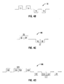
- Figs. 4A - 4C show an output current produced by driving the first and second connections 47a, 47b and 49a, 49b of Fig. 3A at different phases.
- Fig. 4A shows the fundamental amplitude control for the dual-pole circuit 40a.
- Figs. 4B and C show a single cycle of the current waveform as a rectangular waveform.
- the output waveform may have any waveform crest factor (e.g., sinusoidal) and the rectangular waveform is used for illustrative purposes.
- Fig. 4A illustrates that the two phases may be driven in synchrony, while the outputs may be connected to a common return pad, common active electrode, or separate pole pairs of a multi-polar instrument. More specifically, Fig. 4A shows one embodiment of a phase-shifted pulse-width modulated drive for each of the switching components 56a, 58a, 60a, 62a. This controls the average or root mean square ("RMS") output amplitude. The resulting waveform is rectangular. If the bridge circuit (e.g., dual-pole circuit 40a) employs an LCC or any other type of resonant network (e.g., resonant network 50a), then the output waveform is going to sinusoidal. In embodiments, various arbitrary-in-phase synchrony can be utilized to create the other waveforms illustrated in Figs. 4B - 4D .
- RMS root mean square
- a single waveform cycle 70 is shown having a plurality of waveform crests 72, 74, 76, 78 that are generated by activating the first and second connections 47a, 47b and 49a, 49b, at different phases.
- the waveform crest 72 is generated by the switching components 56a and 62a being supplied a first activation pulse for a duration Ton a .
- the switching components 56a and 62a are deactivated during a first deactivation period Toff a , during which time the switching components 56b and 62b are activated by a second activation pulse for a duration Ton b to generate the waveform crest 74.
- the waveform crests 72 and 74 are achieved by activating the switching components 56a and 62a by the first activation pulse at a first phase (e.g., ⁇ a ) and the switching components 56b and 62b by the second activation pulse at a second phase (e.g., ⁇ b ).
- the switching components 56b and 62b are deactivated during a second deactivation period Toff b , during which time the switching components 58a and 60a are activated by a third activation pulse for a duration Ton c to generate the waveform crest 76.
- the switching components 58a and 60a are then deactivated during a third deactivation period Toff c , during which time the switching components 58b and 60b are activated by a fourth activation pulse for a duration Ton d to generate the waveform crest 78.
- the switching components 58b and 60b are then deactivated during a fourth deactivation period Toff d , during which time the cycle 70 repeats and the waveform crest 72 is generated by the switching components 56a and 62a being supplied the first activation pulse.
- the waveform crests 76 and 78 are achieved by activating the switching components 58a and 60a at a third phase (e.g., ⁇ c ) and the switching components 58b and 60b at a fourth phase (e.g., ⁇ d ).
- the drive signals are supplied to the switching components of the first and second connections 47a, 47b and 49a, 49b are phase-shifted.
- ⁇ a may be 0°
- ⁇ b may be 90°
- ⁇ c may be 180°
- ⁇ d may be 270°. More specifically, the first and second phases are 180° out-of-phase with the third and fourth phases, respectively.
- Each of the waveform crests 72, 74, 76, 78 may be supplied individually to each of the output terminals 80a, 82a, 80b, 82b. This allows for generation of multi-polar phase-shifted application of RF energy through a plurality of poles (e.g., instruments 2a, 2b, 2c and return electrode 6 or active electrodes 14a, 14b, 14c and to the return electrode 16) by coupling each of the poles to the corresponding output terminals 80a, 82a, 80b, 82b.
- poles e.g., instruments 2a, 2b, 2c and return electrode 6 or active electrodes 14a, 14b, 14c and to the return electrode 16
- Fig. 4C illustrates another embodiment of the present disclosure, in which two of the first and second connections 47a, 47b and 49a, 49b are driven in parallel or partially in parallel.
- Fig. 4C shows a single waveform cycle 90 is shown having a plurality of waveform crests 92, 93, 94, 96, 97, 98 that are generated by activating the first and second connections 47a, 47b and 49a, 49b, at different phases.
- the wavefonn crest 92 is generated by the switching components 56a and 62a being supplied a first activation pulse for a duration Ton a , during which time the switching components 56b and 62b are activated by a second activation pulse for a duration Ton b to generate the waveform crest 94.
- the first and second activation pulses overlap at least partially, such that the resulting waveform crests 92 and 94 form a single waveform crest 93.
- the waveform crests 92 and 94 are achieved by activating the switching components 56a and 62a by the first activation pulse at a first phase (e.g., ⁇ a ) and the switching components 56b and 62b by the second activation pulse at a second phase (e.g., ⁇ b ) .
- the switching components 56a, 56b and 62a, 62b are deactivated during a second deactivation period Toff b , during which time the switching components 58a and 60a are activated by a third activation pulse for a duration Ton c to generate the waveform crest 96.
- the switching components 58b and 60b are activated by a fourth activation pulse for a duration Ton d to generate the waveform crest 98.
- the third and fourth activation pulses overlap at least partially, such that the resulting waveform crests 96 and 98 form a single waveform crest 97.
- the waveform crests 96 and 98 are achieved by activating the switching components 56a and 62a at a third phase (e.g., ⁇ c ) and the switching components 58b and 60b at a fourth phase (e.g., ⁇ d ).
- the drive signals activating the switching components 58a, 58b, 56a, 56b, 62a, 62b, 60a, 60b are also phase-shifted to provide for multiple overlapping waveforms having waveform crests 92, 96 and 94, 98.
- the output terminals 80a, 82a, 80b, 82b, 80c, 82c, 80d, 82d of the dual-pole circuits 40a, 40b, 40c and 40d are coupled to the active and return terminals 30, 32 for outputting electrosurgical energy to the patient.
- each of the output terminals 80a, 82a, 80b, 82b, 80c, 82c, 80d, 82d may be coupled individually to instruments 2a. 2b, 2c, etc. and to the return electrode 6 to provide for the return flow of the electrosurgical energy.
- each of the output terminals 80a, 82a, 80b, 82b, 80c, 82c, 80d, 82d may be coupled individually to active electrodes 14a, 14b, 14c, etc. and to the return electrode 16.
- a single waveform cycle 100 is shown having a plurality of waveform crests 102, 104, 105, 106, 108, 110, 112, 113, 114, 116 that are generated by activating the first and second connections 47a, 47b, 47c, 47d and 49a, 49b, 49c, 49d at different phases.
- the waveform crest 102 is generated by the switching components 56a and 62a being supplied a first activation pulse for a duration Ton a .
- the switching components 56a and 62a are deactivated during a first deactivation period Toff a , during which time the waveform crest 105 is generated.
- the waveform crest 104 is generated by the switching components 56c and 62c being supplied a second activation pulse for a duration Ton b , during which time the switching components 58d and 60d are activated by a third activation pulse for a duration Ton c to generate the waveform crest 106.
- the first and second activation pulses overlap at least partially, such that the resulting waveform crests 104 and 106 form the waveform crest 105.
- the switching components 56c, 56d and 62c, 62d are deactivated during a second deactivation period Toff b , during which time the switching components 56b and 62b are activated by a fourth activation pulse for a duration Ton d to generate the waveform crest 108.
- the switching components 56b and 62b are deactivated during a third deactivation period Toff c , during which time the switching components 58a and 60a are activated by a fifth activation pulse for a duration Ton e to generate the waveform crest 110.
- the switching components 58a and 60a are then deactivated during a fourth deactivation period Toff d , during which time the waveform crest 113 is generated.
- the switching components 58c and 60c are activated by a sixth activation pulse for a duration Ton f to generate the waveform crest 112.
- the switching components 58d and 60d are activated by a seventh activation pulse for a duration Tong to generate the waveform crest 114.
- the sixth and seventh activation pulses overlap at least partially, such that the resulting waveform crests 112 and 114 form a single waveforms crest 113.
- the switching components 58c, 58d and 60c, 60d are deactivated during a fifth deactivation period Toff e , during which time the switching components 58b and 60b are activated by an eighth activation pulse for a duration Tan h to generate the waveform crest 116.
- the waveform crest 102 is generated by activating the switching components 56a and 62a at a first phase (e.g., ⁇ a ).
- the waveform crests 104 and 106 are achieved by activating the switching components 56c and 62c by the first activation pulse at a second phase (e.g., ⁇ b ) and the switching components 56d and 62d by the second activation pulse at a third phase (e.g., ⁇ c ).
- the waveforms crest 108 is generated by activating the switching components 56b and 62b at a fourth phase (e.g., ⁇ d ).
- the waveform crest 110 is generated by activating the switching components 58a and 60a at a fifth phase (e.g., ⁇ e ).
- the waveform crests 112 and 114 are achieved by activating the switching components 58c and 60c by the sixth activation pulse at a sixth phase (e.g., ⁇ f ) and the switching components 58d and 60d by the second activation pulse at a seventh phase (e.g., ⁇ g ).
- the waveform crest 116 is generated by activating the switching components 56b and 62b at an eighth phase (e.g., ⁇ h ).
- the drive signals are phase-shifted to provide for multiple waveform crests 102, 104, 106, 108, 110, 112, 114, 116.
- the phases may be 45° apart, (e.g., ⁇ a may be 0°, ⁇ b may be 45°, ⁇ c may be 90°, ⁇ d may be 135°, ⁇ e may be 180°, ⁇ f may be 225°, ⁇ g may be 270°, ⁇ h may be 315°). More specifically, the first and fourth phases, the second and fifth, the third and sixth and the fourth and eighth phases are 180° out-of-phase.
- Each of the waveform crests 102, 104, 106, 108, 110, 112, 114, 116 may be supplied individually to each of the output terminals 80a, 82a, 80b, 82b, 80c, 82c, 80d, 82d.
- This allows for generation of multi-polar phase-shifted application of RF energy through a plurality of poles (e.g., instruments 2a, 2b, 2c and return electrode 6 or active electrodes 14a, 14b, 14c and to the return electrode 16) by coupling each of the poles to the corresponding output terminals 80a, 82a, 80b, 82b, 80c, 82c, 80d, 82d.
- poles e.g., instruments 2a, 2b, 2c and return electrode 6 or active electrodes 14a, 14b, 14c and to the return electrode 16
- Fig. 5 shows another embodiment of an output stage 228.
- the output stage 228 includes two or more dual-pole circuits 140a and 140b.
- Each of the dual-pole circuits 140a and 140b is coupled to the HVPS 27 and receives DC voltage therefrom.
- each of the dual-pole assemblies 140a and 140b includes an isolation transformer 141a and 141b, respectively.
- Each of the isolation transformers 141a and 141b includes a primary winding 143a, 143b coupled to a single secondary winding 145.
- the primary windings 143a and 143b include first and second connections 147a, 149a and 147b, 149b, respectively.
- the first connections 147a, 147b include drain supplies 142a, 142b and source supplies 146a, 146b, respectively.
- the second connections 149a, 149b also includes a drain supply 144a, 144b and source supplies 148a, 148b, respectively.
- the drain supplies 142a, 144a, 142b, 144b and source supplies 146a, 148a, 146b, 148b are coupled to the HVPS 27.
- the first connection 147a includes a first pair of switching components 156a and 158a and the second connection 149a includes a second pair of switching components 160a and 162a, respectively.
- the first and second connections 147b and 149b also include first and second pairs of switching components 156b, 158b and 160b, 162b, respectively.
- the switching components 156a, 158a, 160a, 162a and 156b, 158b, 160b, 162b can be, for example, transistors, such as metal-oxide semiconductor field-effect transistors (MOSFET), insulated gate bipolar transistors (IGBT), relays, and the like.
- MOSFET metal-oxide semiconductor field-effect transistors
- IGBT insulated gate bipolar transistors
- the secondary winding 145 includes two output terminals 180 and 182 including a band pass filter 183 coupled therebetween.
- the first and second connections 147a and 149a are connected in series by a resonant network 150a.
- the resonant network 150a may be a series resonant network that includes an inductor 153a and capacitors 152a and 154.
- the network 150a that is arranged in a LCC configuration with the primary winding 143a being coupled between capacitors 152a and 154a.
- the first and second connections 147b and 149b are similarly connected in series by a resonant network 150b having an inductor 153b with the primary winding 143b coupled between capacitors 152b and 154b.
- the output terminals 180 and 182 are coupled to the active and return terminals 30, 32 for outputting electrosurgical energy to the patient.
- one of the terminals 180 and 182 is be coupled to a monopolar instrument (e.g., the instrument 2a) and the other to the return electrode 6 to provide for the return flow of the electrosurgical energy.
- a monopolar instrument e.g., the instrument 2a
- the return electrode 6 to provide for the return flow of the electrosurgical energy.
- bipolar configuration one of the output terminals 180 and 182 is coupled individually to an active electrodes of the forceps 10 (e.g., active electrode 14a) and to the return electrode 16.
- the configuration of multiple primary windings 143a and 143b coupled to a single secondary winding 145 provides for multi-polar phase-shifted application of RF energy through a single pole (e.g., instruments 2a or active electrode 14a).
- a single pole e.g., instruments 2a or active electrode 14a.
- the current passing through each of the primary windings 143a and 143b is monitored and used to ensure that the sum meets the required output power to the tissue being treated.
Landscapes
- Health & Medical Sciences (AREA)
- Surgery (AREA)
- Engineering & Computer Science (AREA)
- Life Sciences & Earth Sciences (AREA)
- Biomedical Technology (AREA)
- Otolaryngology (AREA)
- Nuclear Medicine, Radiotherapy & Molecular Imaging (AREA)
- Plasma & Fusion (AREA)
- Physics & Mathematics (AREA)
- Heart & Thoracic Surgery (AREA)
- Medical Informatics (AREA)
- Molecular Biology (AREA)
- Animal Behavior & Ethology (AREA)
- General Health & Medical Sciences (AREA)
- Public Health (AREA)
- Veterinary Medicine (AREA)
- Surgical Instruments (AREA)
Abstract
Description
- The present disclosure relates to electrosurgical apparatuses, systems and methods. More particularly, the present disclosure is directed to electrosurgical multi-polar electrosurgical systems.
- Energy-based tissue treatment is well known in the art. Various types of energy (e.g., electrical, ultrasonic, microwave, cryogenic, heat, laser, etc.) are applied to tissue to achieve a desired result. Electrosurgery involves application of high radio frequency electrical current to a surgical site to cut, ablate, coagulate or seal tissue.
- In bipolar electrosurgery, one of the electrodes of the hand-held instrument functions as the active electrode and the other as the return electrode. The return electrode is placed in close proximity to the active electrode such that an electrical circuit is formed between the two electrodes (e.g., electrosurgical forceps). In this manner, the applied electrical current is limited to the body tissue positioned between the electrodes. When the electrodes are sufficiently separated from one another, the electrical circuit is open and thus inadvertent contact with body tissue with either of the separated electrodes does not cause current to flow.
- Bipolar electrosurgical techniques and instruments can be used to coagulate blood vessels or tissue, e.g., soft tissue structures, such as lung, brain and intestine. A surgeon can either cauterize, coagulate/desiccate and/or simply reduce or slow bleeding, by controlling the intensity, frequency and duration of the electrosurgical energy applied between the electrodes and through the tissue. In order to achieve one of these desired surgical effects without causing unwanted charring of tissue at the surgical site or causing collateral damage to adjacent tissue, e.g., thermal spread, it is necessary to control the output from the electrosurgical generator, e.g., power, waveforms, voltage, current, pulse rate, etc.
- In monopolar electrosurgery, the active electrode is typically a part of the surgical instrument held by the surgeon that is applied to the tissue to be treated. A patient return electrode is placed remotely from the active electrode to carry the current back to the generator and safely disperse current applied by the active electrode. The return electrodes usually have a large patient contact surface area to minimize heating at that site. Heating is caused by high current densities which directly depend on the surface area. A larger surface contact area results in lower localized heat intensity. Return electrodes are typically sized based on assumptions of the maximum current utilized during a particular surgical procedure and the duty cycle. In bipolar and monopolar modes, it is desirable to utilize more than one active electrode to achieve desired ablation and lesion formation.
- According to one embodiment of the present disclosure, an electrosurgical generator is disclosed. The generator includes a power supply operable to generate a DC voltage and a multi-pole phase-shifted RF output stage coupled to the power supply. The RF output stage includes a plurality of dual-pole circuits, each of the plurality of dual-pole circuits including first and second pairs of switching components. The generator also includes a controller configured to drive the first and second pairs of switching components of each of the plurality of dual-pole circuits at a predetermined phase-shifted frequency.
- According to another embodiment of the present disclosure an electrosurgical system is disclosed. The system includes an electrosurgical generator having a power supply operable to generate a DC voltage. The generator also includes a multi-pole, phase-shifted, pulse-width and/or frequency modulated RF output stage coupled to the power supply. The RF output stage includes an isolation transformer having a secondary winding and a plurality of dual-pole circuits having first and second pairs of switching components and a primary winding coupled to the secondary winding. The generator further includes a controller configured to drive the first and second pairs of switching components of each of the plurality of dual-pole circuits at a predetermined phase-shifted frequency to generate a waveform crest at each of the output terminals. The system also includes a plurality of active electrodes, each of which is coupled to each of the output terminals.
- According to a further embodiment of the present disclosure an electrosurgical system is disclosed. The system includes an electrosurgical generator having a power supply operable to generate a DC voltage. The generator includes a multi-pole, phase-shifted, pulse-width and/or frequency modulated RF output stage coupled to the power supply. The RF output stage includes a plurality of dual-pole circuits, each of the plurality of dual-pole circuits including first and second pairs of switching components, the RF output stage further includes an isolation transformer having a secondary winding and wherein each of the plurality of dual-pole circuits includes a primary winding coupled to the secondary winding. The generator also includes a controller configured to drive the first and second pairs of switching components of each of the plurality of dual-pole circuit at a predetermined phase-shifted frequency. The system includes a plurality of active electrodes, each of which is coupled to each of the output terminals.
- Various embodiments of the present disclosure are described herein with reference to the drawings wherein:
-
Fig. 1 is a perspective view of an electrosurgical system according to one embodiment of the present disclosure; -
Fig. 2 is a schematic block diagram of a generator according to an embodiment of the present disclosure; -
Figs. 3A - 3B are schematic circuit diagrams of a multi-pole phase-shifted radio frequency output stage according to an embodiment of the present disclosure; -
Figs. 4A - 4C illustrate a plurality of waveform cycles generated by the multi-pole phase-shifted radio frequency output stage ofFigs. 3A - 3B according to an embodiment of the present disclosure; and -
Fig. 5 is a schematic circuit diagram of a multi-pole phase-shifted radio frequency output stage according to an embodiment of the present disclosure. - Particular embodiments of the present disclosure are described hereinbelow with reference to the accompanying drawings. In the following description, well-known functions or constructions are not described in detail to avoid obscuring the present disclosure in unnecessary detail.
- The generator according to the present disclosure can perform monopolar and bipolar electrosurgical procedures, including vessel sealing procedures. The generator may include a plurality of outputs for interfacing with various electrosurgical instruments (e.g., a monopolar active electrode, return electrode, bipolar electrosurgical forceps, footswitch, multi-polar ablation needles, etc.). Further, the generator includes electronic circuitry configured for generating radio frequency power specifically suited for various electrosurgical modes (e.g., cutting, blending, division, ablation etc.) and procedures (e.g., monopolar, bipolar, vessel sealing, ablation).
-
Fig. 1 is a schematic illustration of a bipolar and monopolarelectrosurgical system 1 according to one embodiment of the present disclosure. Thesystem 1 includes one or more monopolarelectrosurgical instruments 2a. 2b, 2c, etc. having one or more electrodes for treating tissue of a patient (e.g., electrosurgical cutting probe, ablation electrode(s), etc.). Electrosurgical RF energy is supplied to theinstruments generator 20 via acorresponding supply line Fig. 2 ) of thegenerator 20, allowing theinstruments generator 20 through areturn electrode 6 via areturn line 8 at a return terminal 32 (Fig. 2 ) of thegenerator 20. Thesystem 1 may include a plurality ofreturn electrodes 6 that are arranged to minimize the chances of tissue damage by maximizing the overall contact area with the patient. In addition, thegenerator 20 and thereturn electrode 6 may be configured for monitoring so-called "tissue-to-patient" contact to insure that sufficient contact exists therebetween to further minimize chances of tissue damage. In another embodiment, thesystem 1 also includes amulti-polar ablation device 21 having a plurality ofelectrodes - The
system 1 also includes a bipolarelectrosurgical forceps 10 having one or more pairs of electrodes for treating tissue of a patient. Theelectrosurgical forceps 10 include opposingjaw members active electrodes return electrode 16 disposed therein, respectively. Theactive electrodes return electrode 16 are connected to thegenerator 20 throughcable 18, which includes the supply andreturn lines return terminals electrosurgical forceps 10 are coupled to thegenerator 20 at a connector having connections to the active and returnterminals 30 and 32 (e.g., pins) via a plug disposed at the end of thecable 18, wherein the plug includes contacts from the supply andreturn lines - The
generator 20 may be any suitable type (e.g., electrosurgical, microwave, etc.) and may include a plurality of connectors to accommodate various types of electrosurgical instruments (e.g.,multiple instruments electrosurgical forceps 10, etc.). Further, thegenerator 20 is configured to operate in a variety of modes such as ablation, monopolar and bipolar cutting coagulation, etc. Thegenerator 20 includes suitable input controls (e.g., buttons, activators, switches, touch screen, etc.) for controlling thegenerator 20. In addition, thegenerator 20 may include one or more display screens (not shown) for providing the user with variety of output information (e.g., intensity settings, treatment complete indicators, etc.). The controls allow the user to adjust power of the RF energy, waveform, and other parameters to achieve the desired waveform suitable for a particular task (e.g., coagulating, tissue sealing, ablating, intensity setting, etc.). -
Fig. 2 shows a schematic block diagram of thegenerator 20 having acontroller 24, a high voltage DC power supply 27 ("HVPS") and anRF output stage 28. TheHVPS 27 is connected to an AC source (e.g., electrical wall outlet) and provides high voltage DC power to anRF output stage 28, which then converts high voltage DC power into RF energy and delivers the RF energy to theactive terminal 30. The energy is returned thereto via thereturn terminal 32. In particular, theRF output stage 28 generates sinusoidal or rectangular waveforms of high RF energy. TheRF output stage 28 is configured to generate a plurality of waveforms having various duty cycles, peak voltages, waveform crest factors, and other suitable parameters. Certain types of waveform are suitable for specific electrosurgical modes. For instance, theRF output stage 28 typically generates a 100% duty cycle sinusoidal waveforms in cut mode, which is well-suited for ablating, fusing and dissecting tissue and a 1-25% duty cycle waveform in coagulation mode, which is best used for cauterizing tissue to stop bleeding. - The
controller 24 includes amicroprocessor 25 operably connected to amemory 26, which may be volatile type memory (e.g., RAM) and/or non-volatile type memory (e.g., flash media, disk media, etc.). Themicroprocessor 25 includes an output port that is operably connected to theHVPS 27 and/orRF output stage 28 allowing themicroprocessor 25 to control the output of thegenerator 20 according to either open and/or closed control loop schemes. Those skilled in the art will appreciate that themicroprocessor 25 may be substituted by any logic processor (e.g., control circuit) adapted to perform the calculations discussed herein. - A closed loop control scheme is a feedback control loop, in which a plurality of sensors measure a variety of tissue and energy properties (e.g., tissue impedance, tissue temperature, output current and/or voltage, etc.), and provide feedback to the
controller 24. Such sensors are within the purview of those skilled in the art. Thecontroller 24 then signals theHVPS 27 and/orRF output stage 28, which then adjust DC and/or RF output power, respectively. Thecontroller 24 also receives input signals from the input controls of thegenerator 20, theinstruments forceps 10. Thecontroller 24 utilizes the input signals to adjust power outputted by thegenerator 20 and/or performs other control functions thereon. - The
RF output stage 28 is a multi-pole, phase-shifted, pulse-width and/or frequency modulated RF inverter as shown in more detail inFigs. 3a and3B . As shown inFig. 3A , theRF output stage 28 includes two or more dual-pole circuits pole circuits HVPS 27 and receives DC voltage therefrom. More specifically, each of the dual-pole assemblies primary windings second connections first connections drain supplies source supplies second connections drain supplies source supplies drain supplies HVPS 27. -
First connection 47a includes a first pair of switchingcomponents second connection 49a includes a second pair of switchingcomponents second connections components components - The
secondary windings output terminals output terminals band pass filter second connections resonant network 50a. Theresonant network 50a may be a series resonant network that is arranged in an LCC configuration having aninductor 53a andcapacitors capacitors second connections resonant network 50b with the primary winding 43b coupled betweencapacitors resonant networks -
Output terminals instruments electrodes active electrodes output terminals output terminals return electrode 6, whileoutput terminals - With respect to
Fig. 3B , another embodiment of theRF output stage 28 is shown. TheRF output stage 28 includes four dual-pole circuits pole circuits pole circuits HVPS 27 and receives DC voltage therefrom. Each of the dual-pole circuits primary windings second connections first connections drain supplies source supplies second connections drain supply source supplies drain supplies HVPS 27. - The
first connection 47c includes a first pair of switchingcomponents second connection 49c includes a second pair of switchingcomponents second connections components components - The
secondary windings output terminals output terminals band pass filter 83c and 83d coupled therebetween. The first andsecond connections resonant network 50c having aninductor 53c andcapacitors second connections resonant network 50d having aninductor 53d with the primary winding 43d coupled betweencapacitors resonant networks - The operation of the
RF output stage 28 is described with respect toFig. 3A since the operation of four dual-pole circuits Fig. 3B is substantially similar to that of two dual-pole circuits components controller 24. Thecontroller 24 drives the switchingcomponents generator 20, thereby closing and opening the first andsecond connections switching components controller 24. Thecontroller 24 may include a pulse-width modulated driver for supplying a driver signal to each of the switchingcomponents components second connections components resonant network 50a), the pulse-width or frequency modulation may be used to vary the output amplitude at the load. - The
resonant networks primary windings components capacitors resonant networks resonant networks second connections resonant circuits - During operation,
primary windings secondary windings components components -
Figs. 4A - 4C show an output current produced by driving the first andsecond connections Fig. 3A at different phases.Fig. 4A shows the fundamental amplitude control for the dual-pole circuit 40a.Figs. 4B and C show a single cycle of the current waveform as a rectangular waveform. The output waveform may have any waveform crest factor (e.g., sinusoidal) and the rectangular waveform is used for illustrative purposes. -
Fig. 4A illustrates that the two phases may be driven in synchrony, while the outputs may be connected to a common return pad, common active electrode, or separate pole pairs of a multi-polar instrument. More specifically,Fig. 4A shows one embodiment of a phase-shifted pulse-width modulated drive for each of the switchingcomponents pole circuit 40a) employs an LCC or any other type of resonant network (e.g.,resonant network 50a), then the output waveform is going to sinusoidal. In embodiments, various arbitrary-in-phase synchrony can be utilized to create the other waveforms illustrated inFigs. 4B - 4D . - With reference to
Fig. 4B , asingle waveform cycle 70 is shown having a plurality of waveform crests 72, 74, 76, 78 that are generated by activating the first andsecond connections waveform crest 72 is generated by the switchingcomponents components components waveform crest 74. In other words, the waveform crests 72 and 74 are achieved by activating the switchingcomponents components - The switching
components switching components waveform crest 76. The switchingcomponents components waveform crest 78. The switchingcomponents cycle 70 repeats and thewaveform crest 72 is generated by the switchingcomponents components components second connections - Each of the waveform crests 72, 74, 76, 78 may be supplied individually to each of the
output terminals instruments electrode 6 oractive electrodes corresponding output terminals -
Fig. 4C illustrates another embodiment of the present disclosure, in which two of the first andsecond connections Fig. 4C shows asingle waveform cycle 90 is shown having a plurality of waveform crests 92, 93, 94, 96, 97, 98 that are generated by activating the first andsecond connections wavefonn crest 92 is generated by the switchingcomponents components waveform crest 94. The first and second activation pulses overlap at least partially, such that the resulting waveform crests 92 and 94 form asingle waveform crest 93. The waveform crests 92 and 94 are achieved by activating the switchingcomponents components - The switching
components switching components waveform crest 96. The switchingcomponents waveform crest 98. The third and fourth activation pulses overlap at least partially, such that the resulting waveform crests 96 and 98 form asingle waveform crest 97. The waveform crests 96 and 98 are achieved by activating the switchingcomponents components components - With reference to
Figs. 1 and3B , theoutput terminals pole circuits terminals output terminals instruments 2a. 2b, 2c, etc. and to thereturn electrode 6 to provide for the return flow of the electrosurgical energy. In bipolar configuration, each of theoutput terminals active electrodes return electrode 16. - With reference to
Fig. 4D , asingle waveform cycle 100 is shown having a plurality of waveform crests 102, 104, 105, 106, 108, 110, 112, 113, 114, 116 that are generated by activating the first andsecond connections waveform crest 102 is generated by the switchingcomponents components waveform crest 105 is generated. Thewaveform crest 104 is generated by the switchingcomponents switching components waveform crest 106. The first and second activation pulses overlap at least partially, such that the resulting waveform crests 104 and 106 form thewaveform crest 105. The switchingcomponents components waveform crest 108. - The switching
components switching components waveform crest 110. The switchingcomponents components waveform crest 112. The switchingcomponents waveform crest 114. The sixth and seventh activation pulses overlap at least partially, such that the resulting waveform crests 112 and 114 form a single waveforms crest 113. The switchingcomponents components waveform crest 116. - The
waveform crest 102 is generated by activating the switchingcomponents components components waveforms crest 108 is generated by activating the switchingcomponents waveform crest 110 is generated by activating the switchingcomponents components components waveform crest 116 is generated by activating the switchingcomponents - Each of the waveform crests 102, 104, 106, 108, 110, 112, 114, 116 may be supplied individually to each of the
output terminals instruments electrode 6 oractive electrodes corresponding output terminals -
Fig. 5 shows another embodiment of an output stage 228. The output stage 228 includes two or more dual-pole circuits pole circuits HVPS 27 and receives DC voltage therefrom. More specifically, each of the dual-pole assemblies primary windings second connections drain supplies source supplies second connections drain supply source supplies source supplies HVPS 27. - The first connection 147a includes a first pair of switching
components second connection 149a includes a second pair of switchingcomponents second connections 147b and 149b also include first and second pairs of switchingcomponents components - The secondary winding 145 includes two output terminals 180 and 182 including a band pass filter 183 coupled therebetween. The first and
second connections 147a and 149a are connected in series by aresonant network 150a. Theresonant network 150a may be a series resonant network that includes aninductor 153a andcapacitors 152a and 154. Thenetwork 150a that is arranged in a LCC configuration with the primary winding 143a being coupled betweencapacitors second connections 147b and 149b are similarly connected in series by aresonant network 150b having aninductor 153b with the primary winding 143b coupled betweencapacitors - The output terminals 180 and 182 are coupled to the active and return
terminals instrument 2a) and the other to thereturn electrode 6 to provide for the return flow of the electrosurgical energy. In bipolar configuration, one of the output terminals 180 and 182 is coupled individually to an active electrodes of the forceps 10 (e.g.,active electrode 14a) and to thereturn electrode 16. - The configuration of multiple
primary windings instruments 2a oractive electrode 14a). To ensure that an appropriate amount of current is supplied to the secondary winding 145 from multipleprimary windings primary windings - While several embodiments of the disclosure have been shown in the drawings and/or discussed herein, it is not intended that the disclosure be limited thereto, as it is intended that the disclosure be as broad in scope as the art will allow and that the specification be read likewise. Therefore, the above description should not be construed as limiting, but merely as exemplifications of particular embodiments. Those skilled in the art will envision other modifications within the scope and spirit of the claims appended hereto.
Claims (15)
- An electrosurgical generator, comprising:a power supply operable to generate a DC voltage;a multi-pole phase-shifted RF output stage coupled to the power supply, the RF output stage including a plurality of dual-pole circuits, each of the plurality of dual-pole circuits including first and second pairs of switching components; anda controller configured to drive the first and second pairs of switching components of each of the plurality of dual-pole circuits at a predetermined phase-shifted frequency.
- An electrosurgical generator according to claim 1, wherein the RF output stage includes an isolation transformer having a secondary winding and each of the plurality of dual-pole circuits includes a primary winding coupled to the secondary winding.
- An electrosurgical generator according to claim 1 or 2, wherein the RF output stage is either pulse-width or frequency modulated.
- An electrosurgical generator according to claim 1, 2 or 3, wherein each of the plurality of dual-pole circuits includes an isolation transformer having a primary winding and a secondary winding.
- An electrosurgical generator according to claim 4, wherein the secondary winding includes a pair of output terminals.
- An electrosurgical generator according to claim 4 or 5, wherein the secondary winding includes a band pass filter.
- An electrosurgical generator according to claim 4, 5 or 6, wherein the primary winding includes first and second connections.
- An electrosurgical generator according to claim 7, wherein the primary winding includes a resonant network interconnecting the first and second connections.
- An electrosurgical system, comprising:an electrosurgical generator as defined in any one of claims 4 to 8, wherein the secondary winding includes a pair of output terminals, andthe controller is configured to drive the first and second pairs of switching components of each of the plurality of dual-pole circuit at the predetermined phase-shifted frequency to generate a waveform crest at each of the output terminals; anda plurality of active electrodes, each of which is coupled to each of the output terminals.
- An electrosurgical system according to claim 9, wherein at least two of waveform crests at least partially overlap.
- An electrosurgical system, comprising:an electrosurgical generator including:a power supply operable to generate a DC voltage;a multi-pole phase-shifted RF output stage coupled to the power supply, the RF output stage including:an isolation transformer having a secondary winding; anda plurality of dual-pole circuits having first and second pairs of switching components and a primary winding coupled to the secondary winding;a controller configured to drive the first and second pairs of switching components of each of the plurality of dual-pole circuit at a predetermined phase-shifted frequency;anda plurality of active electrodes, each of which is coupled to each of the output terminals.
- An electrosurgical generator according to claim 11, wherein the secondary winding includes a band pass filter.
- An electrosurgical generator according to claim 11 or 12, wherein the primary winding includes first and second connections.
- An electrosurgical generator according to claim 13, wherein the primary winding includes a resonant network interconnecting the first and second connections.
- An electrosurgical generator according to claim 11, 12, 13 or 14, wherein the RF output stage is either pulse-width or frequency modulated.
Applications Claiming Priority (1)
| Application Number | Priority Date | Filing Date | Title |
|---|---|---|---|
| US12/566,200 US8685015B2 (en) | 2009-09-24 | 2009-09-24 | System and method for multi-pole phase-shifted radio frequency application |
Publications (2)
| Publication Number | Publication Date |
|---|---|
| EP2366351A1 true EP2366351A1 (en) | 2011-09-21 |
| EP2366351B1 EP2366351B1 (en) | 2018-04-04 |
Family
ID=43533386
Family Applications (1)
| Application Number | Title | Priority Date | Filing Date |
|---|---|---|---|
| EP10179305.7A Not-in-force EP2366351B1 (en) | 2009-09-24 | 2010-09-24 | System for multi-pole phase-shifted radio frequency application |
Country Status (3)
| Country | Link |
|---|---|
| US (1) | US8685015B2 (en) |
| EP (1) | EP2366351B1 (en) |
| CA (1) | CA2715464C (en) |
Families Citing this family (16)
| Publication number | Priority date | Publication date | Assignee | Title |
|---|---|---|---|---|
| US8235983B2 (en) | 2007-07-12 | 2012-08-07 | Asthmatx, Inc. | Systems and methods for delivering energy to passageways in a patient |
| PL2676624T3 (en) * | 2012-06-18 | 2017-06-30 | Erbe Elektromedizin Gmbh | High frequency surgical device |
| US10842563B2 (en) * | 2013-03-15 | 2020-11-24 | Covidien Lp | System and method for power control of electrosurgical resonant inverters |
| US9283028B2 (en) * | 2013-03-15 | 2016-03-15 | Covidien Lp | Crest-factor control of phase-shifted inverter |
| US9814618B2 (en) | 2013-06-06 | 2017-11-14 | Boston Scientific Scimed, Inc. | Devices for delivering energy and related methods of use |
| US9559594B2 (en) | 2013-06-24 | 2017-01-31 | Covidien Lp | Dead-time optimization of resonant inverters |
| US10729484B2 (en) | 2013-07-16 | 2020-08-04 | Covidien Lp | Electrosurgical generator with continuously and arbitrarily variable crest factor |
| US9913679B2 (en) | 2013-10-16 | 2018-03-13 | Covidien Lp | Electrosurgical systems and methods for monitoring power dosage |
| US10188446B2 (en) | 2013-10-16 | 2019-01-29 | Covidien Lp | Resonant inverter |
| US9642670B2 (en) | 2013-10-29 | 2017-05-09 | Covidien Lp | Resonant inverter with a common mode choke |
| US10492850B2 (en) | 2014-04-04 | 2019-12-03 | Covidien Lp | Systems and methods for calculating tissue impedance in electrosurgery |
| US20210361339A1 (en) * | 2020-05-21 | 2021-11-25 | Covidien Lp | Independent control of dual rf monopolar electrosurgery with shared return electrode |
| US20210361340A1 (en) * | 2020-05-21 | 2021-11-25 | Covidien Lp | Independent control of dual rf electrosurgery |
| WO2021263007A1 (en) * | 2020-06-24 | 2021-12-30 | Medtronic, Inc. | Split biphasic waveform for embolic reduction |
| US20220160421A1 (en) * | 2020-11-25 | 2022-05-26 | Biosense Webster (Israel) Ltd. | Single frequency switch mode power supply generator with phase shifter |
| CN116236691A (en) * | 2023-03-17 | 2023-06-09 | 上海杉翎医疗科技有限公司 | Implantable stimulation systems, methods, computer devices, and storage media |
Citations (4)
| Publication number | Priority date | Publication date | Assignee | Title |
|---|---|---|---|---|
| EP1681026A2 (en) * | 2005-01-13 | 2006-07-19 | Sherwood Services AG | Circuit and method for controlling an electrosurgical generator using a full bridge topology |
| WO2008101356A1 (en) * | 2007-02-25 | 2008-08-28 | Baylis Medical Company Inc. | Methods for control of energy delivery to multiple energy delivery devices |
| EP2100566A1 (en) * | 2008-03-13 | 2009-09-16 | Tyco Healthcare Group, LP | Crest factor enhancement in electrosurgical generators |
| US20100114090A1 (en) * | 2008-05-23 | 2010-05-06 | Gyrus Medical Limited | Electrosurgical generator and system |
Family Cites Families (141)
| Publication number | Priority date | Publication date | Assignee | Title |
|---|---|---|---|---|
| DE179607C (en) | 1906-11-12 | |||
| DE390937C (en) | 1922-10-13 | 1924-03-03 | Adolf Erb | Device for internal heating of furnace furnaces for hardening, tempering, annealing, quenching and melting |
| DE1099658B (en) | 1959-04-29 | 1961-02-16 | Siemens Reiniger Werke Ag | Automatic switch-on device for high-frequency surgical devices |
| FR1275415A (en) | 1960-09-26 | 1961-11-10 | Device for detecting disturbances for electrical installations, in particular electrosurgery | |
| DE1139927B (en) | 1961-01-03 | 1962-11-22 | Friedrich Laber | High-frequency surgical device |
| DE1149832C2 (en) | 1961-02-25 | 1977-10-13 | Siemens AG, 1000 Berlin und 8000 München | HIGH FREQUENCY SURGICAL EQUIPMENT |
| FR1347865A (en) | 1962-11-22 | 1964-01-04 | Improvements to diathermo-coagulation devices | |
| DE1439302B2 (en) | 1963-10-26 | 1971-05-19 | Siemens AG, 1000 Berlin u 8000 München | High frequency surgical device |
| US3495584A (en) * | 1965-06-03 | 1970-02-17 | Gen Electric | Lead failure detection circuit for a cardiac monitor |
| US3826263A (en) * | 1970-08-13 | 1974-07-30 | R Shaw | Electrically heated surgical cutting instrument |
| US3971365A (en) * | 1973-02-12 | 1976-07-27 | Beckman Instruments, Inc. | Bioelectrical impedance measuring system |
| GB1480736A (en) | 1973-08-23 | 1977-07-20 | Matburn Ltd | Electrodiathermy apparatus |
| FR2251864A1 (en) | 1973-11-21 | 1975-06-13 | Termiflex Corp | Portable input and output unit for connection to a data processor - is basically a calculator with transmitter and receiver |
| DE2407559C3 (en) | 1974-02-16 | 1982-01-21 | Dornier System Gmbh, 7990 Friedrichshafen | Heat probe |
| US4237887A (en) | 1975-01-23 | 1980-12-09 | Valleylab, Inc. | Electrosurgical device |
| DE2504280C3 (en) * | 1975-02-01 | 1980-08-28 | Hans Heinrich Prof. Dr. 8035 Gauting Meinke | Device for cutting and / or coagulating human tissue with high frequency current |
| CA1064581A (en) | 1975-06-02 | 1979-10-16 | Stephen W. Andrews | Pulse control circuit and method for electrosurgical units |
| DE2540968C2 (en) | 1975-09-13 | 1982-12-30 | Erbe Elektromedizin GmbH, 7400 Tübingen | Device for switching on the coagulation current of a bipolar coagulation forceps |
| US4094320A (en) | 1976-09-09 | 1978-06-13 | Valleylab, Inc. | Electrosurgical safety circuit and method of using same |
| FR2390968A1 (en) | 1977-05-16 | 1978-12-15 | Skovajsa Joseph | Local acupuncture treatment appts. - has oblong head with end aperture and contains laser diode unit (NL 20.11.78) |
| SU727201A2 (en) | 1977-11-02 | 1980-04-15 | Киевский Научно-Исследовательский Институт Нейрохирургии | Electric surgical apparatus |
| DE2803275C3 (en) | 1978-01-26 | 1980-09-25 | Aesculap-Werke Ag Vormals Jetter & Scheerer, 7200 Tuttlingen | Remote switching device for switching a monopolar HF surgical device |
| DE2823291A1 (en) | 1978-05-27 | 1979-11-29 | Rainer Ing Grad Koch | Coagulation instrument automatic HF switching circuit - has first lead to potentiometer and second to transistor base |
| DE2946728A1 (en) | 1979-11-20 | 1981-05-27 | Erbe Elektromedizin GmbH & Co KG, 7400 Tübingen | HF surgical appts. for use with endoscope - provides cutting or coagulation current at preset intervals and of selected duration |
| JPS5778844A (en) | 1980-11-04 | 1982-05-17 | Kogyo Gijutsuin | Lasre knife |
| DE3045996A1 (en) | 1980-12-05 | 1982-07-08 | Medic Eschmann Handelsgesellschaft für medizinische Instrumente mbH, 2000 Hamburg | Electro-surgical scalpel instrument - has power supply remotely controlled by surgeon |
| FR2502935B1 (en) | 1981-03-31 | 1985-10-04 | Dolley Roger | METHOD AND DEVICE FOR CONTROLLING THE COAGULATION OF TISSUES USING A HIGH FREQUENCY CURRENT |
| DE3120102A1 (en) | 1981-05-20 | 1982-12-09 | F.L. Fischer GmbH & Co, 7800 Freiburg | ARRANGEMENT FOR HIGH-FREQUENCY COAGULATION OF EGG WHITE FOR SURGICAL PURPOSES |
| FR2517953A1 (en) | 1981-12-10 | 1983-06-17 | Alvar Electronic | Diaphanometer for optical examination of breast tissue structure - measures tissue transparency using two plates and optical fibre bundle cooperating with photoelectric cells |
| DE3378719D1 (en) * | 1983-05-24 | 1989-01-26 | Chang Sien Shih | Electro-surgical unit control apparatus |
| GB8401887D0 (en) * | 1984-01-25 | 1984-02-29 | Matburn Holdings Ltd | Electrosurgical unit |
| US4727874A (en) * | 1984-09-10 | 1988-03-01 | C. R. Bard, Inc. | Electrosurgical generator with high-frequency pulse width modulated feedback power control |
| FR2573301B3 (en) | 1984-11-16 | 1987-04-30 | Lamidey Gilles | SURGICAL PLIERS AND ITS CONTROL AND CONTROL APPARATUS |
| DE3510586A1 (en) | 1985-03-23 | 1986-10-02 | Erbe Elektromedizin GmbH, 7400 Tübingen | Control device for a high-frequency surgical instrument |
| DE3604823C2 (en) | 1986-02-15 | 1995-06-01 | Lindenmeier Heinz | High frequency generator with automatic power control for high frequency surgery |
| EP0246350A1 (en) | 1986-05-23 | 1987-11-25 | Erbe Elektromedizin GmbH. | Coagulation electrode |
| EP0253012B1 (en) * | 1986-07-17 | 1992-01-22 | Erbe Elektromedizin GmbH. | High-frequency surgical apparatus for thermally coagulating biological tissues |
| US4767999A (en) * | 1986-11-12 | 1988-08-30 | Megapulse, Inc. | Method of and apparatus for radio-frequency generation in resonator tank circuits excited by sequential pulses of alternately opposite polarity |
| US4931047A (en) | 1987-09-30 | 1990-06-05 | Cavitron, Inc. | Method and apparatus for providing enhanced tissue fragmentation and/or hemostasis |
| EP0325456B1 (en) | 1988-01-20 | 1995-12-27 | G2 Design Limited | Diathermy unit |
| EP0336742A3 (en) | 1988-04-08 | 1990-05-16 | Bristol-Myers Company | Method and apparatus for the calibration of electrosurgical apparatus |
| DE3815835A1 (en) * | 1988-05-09 | 1989-11-23 | Flachenecker Gerhard | HIGH FREQUENCY GENERATOR FOR TISSUE CUTTING AND COAGULATION IN HIGH FREQUENCY SURGERY |
| DE3824970C2 (en) * | 1988-07-22 | 1999-04-01 | Lindenmeier Heinz | Feedback high frequency power oscillator |
| DE3904558C2 (en) | 1989-02-15 | 1997-09-18 | Lindenmeier Heinz | Automatically power-controlled high-frequency generator for high-frequency surgery |
| EP0390937B1 (en) | 1989-04-01 | 1994-11-02 | Erbe Elektromedizin GmbH | Device for the surveillance of the adherence of neutral electrodes in high-frequency surgery |
| DE3942998C2 (en) | 1989-12-27 | 1998-11-26 | Delma Elektro Med App | High frequency electrosurgical unit |
| US20010051803A1 (en) | 1991-07-05 | 2001-12-13 | Desai Jawahar M. | Device and method for multi-phase radio-frequency ablation |
| US5620481A (en) * | 1991-07-05 | 1997-04-15 | Desai; Jawahar M. | Device for multi-phase radio-frequency ablation |
| US5383917A (en) * | 1991-07-05 | 1995-01-24 | Jawahar M. Desai | Device and method for multi-phase radio-frequency ablation |
| CA2106410C (en) * | 1991-11-08 | 2004-07-06 | Stuart D. Edwards | Ablation electrode with insulated temperature sensing elements |
| US5383874A (en) * | 1991-11-08 | 1995-01-24 | Ep Technologies, Inc. | Systems for identifying catheters and monitoring their use |
| JPH07500756A (en) * | 1991-11-08 | 1995-01-26 | イーピー テクノロジーズ,インコーポレイテッド | Radiofrequency ablation with phase-sensitive power detection |
| US6142992A (en) * | 1993-05-10 | 2000-11-07 | Arthrocare Corporation | Power supply for limiting power in electrosurgery |
| DE4205213A1 (en) | 1992-02-20 | 1993-08-26 | Delma Elektro Med App | HIGH FREQUENCY SURGERY DEVICE |
| US5300070A (en) * | 1992-03-17 | 1994-04-05 | Conmed Corporation | Electrosurgical trocar assembly with bi-polar electrode |
| US5281213A (en) * | 1992-04-16 | 1994-01-25 | Implemed, Inc. | Catheter for ice mapping and ablation |
| US5414238A (en) * | 1992-10-02 | 1995-05-09 | Martin Marietta Corporation | Resonant power supply for an arcjet thruster |
| WO1994010922A1 (en) * | 1992-11-13 | 1994-05-26 | Ep Technologies, Inc. | Cardial ablation systems using temperature monitoring |
| US5348554A (en) | 1992-12-01 | 1994-09-20 | Cardiac Pathways Corporation | Catheter for RF ablation with cooled electrode |
| US5430434A (en) * | 1993-02-24 | 1995-07-04 | Lederer; Gabor | Portable surgical early warning device |
| US5370645A (en) * | 1993-04-19 | 1994-12-06 | Valleylab Inc. | Electrosurgical processor and method of use |
| GB9314391D0 (en) * | 1993-07-12 | 1993-08-25 | Gyrus Medical Ltd | A radio frequency oscillator and an electrosurgical generator incorporating such an oscillator |
| US5817093A (en) * | 1993-07-22 | 1998-10-06 | Ethicon Endo-Surgery, Inc. | Impedance feedback monitor with query electrode for electrosurgical instrument |
| US5372596A (en) * | 1993-07-27 | 1994-12-13 | Valleylab Inc. | Apparatus for leakage control and method for its use |
| DE4339049C2 (en) | 1993-11-16 | 2001-06-28 | Erbe Elektromedizin | Surgical system configuration facility |
| GB9400954D0 (en) * | 1994-01-19 | 1994-03-16 | Smiths Industries Plc | Electrosurgery apparatus |
| US5696441A (en) * | 1994-05-13 | 1997-12-09 | Distribution Control Systems, Inc. | Linear alternating current interface for electronic meters |
| EP0957792A4 (en) * | 1995-05-02 | 2000-09-20 | Heart Rhythm Tech Inc | System for controlling the energy delivered to a patient for ablation |
| US6293942B1 (en) | 1995-06-23 | 2001-09-25 | Gyrus Medical Limited | Electrosurgical generator method |
| GB9526627D0 (en) * | 1995-12-29 | 1996-02-28 | Gyrus Medical Ltd | An electrosurgical instrument and an electrosurgical electrode assembly |
| DE19643127A1 (en) | 1996-10-18 | 1998-04-23 | Berchtold Gmbh & Co Geb | High frequency surgical device and method for its operation |
| US6063078A (en) * | 1997-03-12 | 2000-05-16 | Medtronic, Inc. | Method and apparatus for tissue ablation |
| WO1998044856A1 (en) | 1997-04-04 | 1998-10-15 | Minnesota Mining And Manufacturing Company | Method and apparatus for controlling contact of biomedical electrodes with patient skin |
| DE19714972C2 (en) | 1997-04-10 | 2001-12-06 | Storz Endoskop Gmbh Schaffhaus | Device for monitoring the application of a neutral electrode |
| GB9708268D0 (en) | 1997-04-24 | 1997-06-18 | Gyrus Medical Ltd | An electrosurgical instrument |
| DE19717411A1 (en) | 1997-04-25 | 1998-11-05 | Aesculap Ag & Co Kg | Monitoring of thermal loading of patient tissue in contact region of neutral electrode of HF treatment unit |
| US5838558A (en) | 1997-05-19 | 1998-11-17 | Trw Inc. | Phase staggered full-bridge converter with soft-PWM switching |
| US6007532A (en) * | 1997-08-29 | 1999-12-28 | 3M Innovative Properties Company | Method and apparatus for detecting loss of contact of biomedical electrodes with patient skin |
| US6309386B1 (en) | 1997-10-06 | 2001-10-30 | Somnus Medical Technologies, Inc. | Linear power control with PSK regulation |
| DE19757720A1 (en) * | 1997-12-23 | 1999-06-24 | Sulzer Osypka Gmbh | Method for operating a high-frequency ablation device and device for high-frequency tissue ablation |
| US6657173B2 (en) | 1998-04-21 | 2003-12-02 | State Board Of Higher Education On Behalf Of Oregon State University | Variable frequency automated capacitive radio frequency (RF) dielectric heating system |
| US6171305B1 (en) * | 1998-05-05 | 2001-01-09 | Cardiac Pacemakers, Inc. | RF ablation apparatus and method having high output impedance drivers |
| US6508815B1 (en) * | 1998-05-08 | 2003-01-21 | Novacept | Radio-frequency generator for powering an ablation device |
| DE19848540A1 (en) | 1998-10-21 | 2000-05-25 | Reinhard Kalfhaus | Circuit layout and method for operating a single- or multiphase current inverter connects an AC voltage output to a primary winding and current and a working resistance to a transformer's secondary winding and current. |
| US6423057B1 (en) | 1999-01-25 | 2002-07-23 | The Arizona Board Of Regents On Behalf Of The University Of Arizona | Method and apparatus for monitoring and controlling tissue temperature and lesion formation in radio-frequency ablation procedures |
| US6203541B1 (en) | 1999-04-23 | 2001-03-20 | Sherwood Services Ag | Automatic activation of electrosurgical generator bipolar output |
| US6696844B2 (en) | 1999-06-04 | 2004-02-24 | Engineering & Research Associates, Inc. | Apparatus and method for real time determination of materials' electrical properties |
| CA2416581A1 (en) | 2000-07-25 | 2002-04-25 | Rita Medical Systems, Inc. | Apparatus for detecting and treating tumors using localized impedance measurement |
| EP1307154B1 (en) | 2000-08-08 | 2005-02-23 | Erbe Elektromedizin GmbH | High-frequency generator for performing high-frequency surgery having adjustable power limitation |
| US6730080B2 (en) | 2000-08-23 | 2004-05-04 | Olympus Corporation | Electric operation apparatus |
| US6743225B2 (en) | 2001-03-27 | 2004-06-01 | Uab Research Foundation | Electrophysiologic measure of endpoints for ablation lesions created in fibrillating substrates |
| US6923804B2 (en) | 2001-07-12 | 2005-08-02 | Neothermia Corporation | Electrosurgical generator |
| US6740079B1 (en) | 2001-07-12 | 2004-05-25 | Neothermia Corporation | Electrosurgical generator |
| US6929641B2 (en) * | 2001-08-27 | 2005-08-16 | Gyrus Medical Limited | Electrosurgical system |
| US6997935B2 (en) * | 2001-11-20 | 2006-02-14 | Advanced Medical Optics, Inc. | Resonant converter tuning for maintaining substantially constant phaco handpiece power under increased load |
| DE10218895B4 (en) | 2002-04-26 | 2006-12-21 | Storz Endoskop Produktions Gmbh | High-frequency surgical generator |
| US7044948B2 (en) * | 2002-12-10 | 2006-05-16 | Sherwood Services Ag | Circuit for controlling arc energy from an electrosurgical generator |
| EP1617776B1 (en) | 2003-05-01 | 2015-09-02 | Covidien AG | System for programing and controlling an electrosurgical generator system |
| US7396336B2 (en) * | 2003-10-30 | 2008-07-08 | Sherwood Services Ag | Switched resonant ultrasonic power amplifier system |
| EP1684654B1 (en) | 2003-10-30 | 2014-11-12 | Covidien AG | Automatic control system for an electrosurgical generator |
| US7115124B1 (en) | 2003-11-12 | 2006-10-03 | Jia Hua Xiao | Device and method for tissue ablation using bipolar radio-frequency current |
| US7300435B2 (en) | 2003-11-21 | 2007-11-27 | Sherwood Services Ag | Automatic control system for an electrosurgical generator |
| ES2323793T3 (en) * | 2004-03-26 | 2009-07-24 | Unomedical A/S | INFUSION SET |
| DE102004025613B4 (en) | 2004-05-25 | 2008-08-07 | Erbe Elektromedizin Gmbh | Method and measuring device for determining the transition impedance between two partial electrodes of a divided neutral electrode |
| DE102004054575A1 (en) | 2004-11-11 | 2006-05-24 | Erbe Elektromedizin Gmbh | Control for an electrosurgical unit |
| US9474564B2 (en) | 2005-03-31 | 2016-10-25 | Covidien Ag | Method and system for compensating for external impedance of an energy carrying component when controlling an electrosurgical generator |
| US8734438B2 (en) | 2005-10-21 | 2014-05-27 | Covidien Ag | Circuit and method for reducing stored energy in an electrosurgical generator |
| US20070173813A1 (en) * | 2006-01-24 | 2007-07-26 | Sherwood Services Ag | System and method for tissue sealing |
| US7648499B2 (en) | 2006-03-21 | 2010-01-19 | Covidien Ag | System and method for generating radio frequency energy |
| US8817656B2 (en) * | 2008-04-08 | 2014-08-26 | Cisco Technology, Inc. | Discovery for fibre channel over ethernet devices |
| GB0809461D0 (en) * | 2008-05-23 | 2008-07-02 | Gyrus Medical Ltd | An electrosurgical generator and system |
| US8226639B2 (en) * | 2008-06-10 | 2012-07-24 | Tyco Healthcare Group Lp | System and method for output control of electrosurgical generator |
| US9700366B2 (en) * | 2008-08-01 | 2017-07-11 | Covidien Lp | Polyphase electrosurgical system and method |
| US8403924B2 (en) * | 2008-09-03 | 2013-03-26 | Vivant Medical, Inc. | Shielding for an isolation apparatus used in a microwave generator |
| US8287529B2 (en) * | 2008-09-05 | 2012-10-16 | Tyco Healthcare Group Lp | Electrosurgical apparatus with high speed energy recovery |
| US8377053B2 (en) * | 2008-09-05 | 2013-02-19 | Covidien Lp | Electrosurgical apparatus with high speed energy recovery |
| US8248075B2 (en) * | 2008-09-30 | 2012-08-21 | Vivant Medical, Inc. | System, apparatus and method for dissipating standing wave in a microwave delivery system |
| US8242782B2 (en) * | 2008-09-30 | 2012-08-14 | Vivant Medical, Inc. | Microwave ablation generator control system |
| US8287527B2 (en) * | 2008-09-30 | 2012-10-16 | Vivant Medical, Inc. | Microwave system calibration apparatus and method of use |
| US8180433B2 (en) * | 2008-09-30 | 2012-05-15 | Vivant Medical, Inc. | Microwave system calibration apparatus, system and method of use |
| US8346370B2 (en) * | 2008-09-30 | 2013-01-01 | Vivant Medical, Inc. | Delivered energy generator for microwave ablation |
| US8174267B2 (en) * | 2008-09-30 | 2012-05-08 | Vivant Medical, Inc. | Intermittent microwave energy delivery system |
| US20100082083A1 (en) * | 2008-09-30 | 2010-04-01 | Brannan Joseph D | Microwave system tuner |
| US8852179B2 (en) * | 2008-10-10 | 2014-10-07 | Covidien Lp | Apparatus, system and method for monitoring tissue during an electrosurgical procedure |
| US8734444B2 (en) * | 2008-10-10 | 2014-05-27 | Covidien Lp | System and method for delivering high current to electrosurgical device |
| US8211100B2 (en) * | 2009-01-12 | 2012-07-03 | Tyco Healthcare Group Lp | Energy delivery algorithm for medical devices based on maintaining a fixed position on a tissue electrical conductivity v. temperature curve |
| US8333759B2 (en) * | 2009-01-12 | 2012-12-18 | Covidien Lp | Energy delivery algorithm for medical devices |
| US8162932B2 (en) * | 2009-01-12 | 2012-04-24 | Tyco Healthcare Group Lp | Energy delivery algorithm impedance trend adaptation |
| US8167875B2 (en) * | 2009-01-12 | 2012-05-01 | Tyco Healthcare Group Lp | Energy delivery algorithm for medical devices |
| US8152802B2 (en) * | 2009-01-12 | 2012-04-10 | Tyco Healthcare Group Lp | Energy delivery algorithm filter pre-loading |
| US8231553B2 (en) * | 2009-01-13 | 2012-07-31 | Tyco Healthcare Group Lp | Method for wireless control of electrosurgery |
| US8235917B2 (en) * | 2009-01-13 | 2012-08-07 | Tyco Healthcare Group Lp | Wireless electrosurgical controller |
| US8257350B2 (en) * | 2009-06-17 | 2012-09-04 | Arthrocare Corporation | Method and system of an electrosurgical controller with wave-shaping |
| US8932282B2 (en) * | 2009-08-03 | 2015-01-13 | Covidien Lp | Power level transitioning in a surgical instrument |
| US7956620B2 (en) * | 2009-08-12 | 2011-06-07 | Tyco Healthcare Group Lp | System and method for augmented impedance sensing |
| US8790335B2 (en) * | 2009-08-28 | 2014-07-29 | Covidien Lp | Electrosurgical generator |
| US8382751B2 (en) * | 2009-09-10 | 2013-02-26 | Covidien Lp | System and method for power supply noise reduction |
| US20110071516A1 (en) * | 2009-09-24 | 2011-03-24 | Tyco Healthcare Group Lp | System and Method for Controlling Electrosurgical Output |
| US8377054B2 (en) * | 2009-09-24 | 2013-02-19 | Covidien Lp | Automatic control circuit for use in an electrosurgical generator |
| US8652125B2 (en) * | 2009-09-28 | 2014-02-18 | Covidien Lp | Electrosurgical generator user interface |
| US20110112530A1 (en) * | 2009-11-06 | 2011-05-12 | Keller Craig A | Battery Powered Electrosurgery |
-
2009
- 2009-09-24 US US12/566,200 patent/US8685015B2/en active Active
-
2010
- 2010-09-23 CA CA2715464A patent/CA2715464C/en not_active Expired - Fee Related
- 2010-09-24 EP EP10179305.7A patent/EP2366351B1/en not_active Not-in-force
Patent Citations (4)
| Publication number | Priority date | Publication date | Assignee | Title |
|---|---|---|---|---|
| EP1681026A2 (en) * | 2005-01-13 | 2006-07-19 | Sherwood Services AG | Circuit and method for controlling an electrosurgical generator using a full bridge topology |
| WO2008101356A1 (en) * | 2007-02-25 | 2008-08-28 | Baylis Medical Company Inc. | Methods for control of energy delivery to multiple energy delivery devices |
| EP2100566A1 (en) * | 2008-03-13 | 2009-09-16 | Tyco Healthcare Group, LP | Crest factor enhancement in electrosurgical generators |
| US20100114090A1 (en) * | 2008-05-23 | 2010-05-06 | Gyrus Medical Limited | Electrosurgical generator and system |
Also Published As
| Publication number | Publication date |
|---|---|
| US20110071518A1 (en) | 2011-03-24 |
| EP2366351B1 (en) | 2018-04-04 |
| CA2715464C (en) | 2018-08-07 |
| US8685015B2 (en) | 2014-04-01 |
| CA2715464A1 (en) | 2011-03-24 |
Similar Documents
| Publication | Publication Date | Title |
|---|---|---|
| EP2366351B1 (en) | System for multi-pole phase-shifted radio frequency application | |
| US11864814B2 (en) | System and method for harmonic control of dual-output generators | |
| US9522038B2 (en) | Crest factor enhancement in electrosurgical generators | |
| CA2845763C (en) | Crest-factor control of phase-shifted inverter | |
| EP2301464B1 (en) | Electrosurgical generator user interface | |
| CN103635157B (en) | Electrosurgical apparatus with real-time RF tissue energy control | |
| JP2011161230A (en) | Square wave for vessel sealing | |
| US10869712B2 (en) | System and method for high frequency leakage reduction through selective harmonic elimination in electrosurgical generators | |
| JP2012005840A (en) | Current-fed push-pull converter with passive voltage clamp | |
| US9522039B2 (en) | Crest factor enhancement in electrosurgical generators |
Legal Events
| Date | Code | Title | Description |
|---|---|---|---|
| PUAI | Public reference made under article 153(3) epc to a published international application that has entered the european phase |
Free format text: ORIGINAL CODE: 0009012 |
|
| AK | Designated contracting states |
Kind code of ref document: A1 Designated state(s): AL AT BE BG CH CY CZ DE DK EE ES FI FR GB GR HR HU IE IS IT LI LT LU LV MC MK MT NL NO PL PT RO SE SI SK SM TR |
|
| AX | Request for extension of the european patent |
Extension state: BA ME RS |
|
| 17P | Request for examination filed |
Effective date: 20120316 |
|
| RAP1 | Party data changed (applicant data changed or rights of an application transferred) |
Owner name: COVIDIEN LP |
|
| RIC1 | Information provided on ipc code assigned before grant |
Ipc: A61B 18/14 20060101ALI20170925BHEP Ipc: A61B 18/12 20060101AFI20170925BHEP Ipc: A61B 18/00 20060101ALI20170925BHEP |
|
| GRAP | Despatch of communication of intention to grant a patent |
Free format text: ORIGINAL CODE: EPIDOSNIGR1 |
|
| INTG | Intention to grant announced |
Effective date: 20171117 |
|
| GRAS | Grant fee paid |
Free format text: ORIGINAL CODE: EPIDOSNIGR3 |
|
| GRAA | (expected) grant |
Free format text: ORIGINAL CODE: 0009210 |
|
| AK | Designated contracting states |
Kind code of ref document: B1 Designated state(s): AL AT BE BG CH CY CZ DE DK EE ES FI FR GB GR HR HU IE IS IT LI LT LU LV MC MK MT NL NO PL PT RO SE SI SK SM TR |
|
| REG | Reference to a national code |
Ref country code: GB Ref legal event code: FG4D |
|
| REG | Reference to a national code |
Ref country code: CH Ref legal event code: EP |
|
| REG | Reference to a national code |
Ref country code: AT Ref legal event code: REF Ref document number: 984721 Country of ref document: AT Kind code of ref document: T Effective date: 20180415 |
|
| REG | Reference to a national code |
Ref country code: IE Ref legal event code: FG4D |
|
| REG | Reference to a national code |
Ref country code: DE Ref legal event code: R096 Ref document number: 602010049611 Country of ref document: DE |
|
| REG | Reference to a national code |
Ref country code: NL Ref legal event code: MP Effective date: 20180404 |
|
| REG | Reference to a national code |
Ref country code: FR Ref legal event code: PLFP Year of fee payment: 9 |
|
| REG | Reference to a national code |
Ref country code: LT Ref legal event code: MG4D |
|
| PG25 | Lapsed in a contracting state [announced via postgrant information from national office to epo] |
Ref country code: NL Free format text: LAPSE BECAUSE OF FAILURE TO SUBMIT A TRANSLATION OF THE DESCRIPTION OR TO PAY THE FEE WITHIN THE PRESCRIBED TIME-LIMIT Effective date: 20180404 |
|
| PG25 | Lapsed in a contracting state [announced via postgrant information from national office to epo] |
Ref country code: PL Free format text: LAPSE BECAUSE OF FAILURE TO SUBMIT A TRANSLATION OF THE DESCRIPTION OR TO PAY THE FEE WITHIN THE PRESCRIBED TIME-LIMIT Effective date: 20180404 Ref country code: FI Free format text: LAPSE BECAUSE OF FAILURE TO SUBMIT A TRANSLATION OF THE DESCRIPTION OR TO PAY THE FEE WITHIN THE PRESCRIBED TIME-LIMIT Effective date: 20180404 Ref country code: LT Free format text: LAPSE BECAUSE OF FAILURE TO SUBMIT A TRANSLATION OF THE DESCRIPTION OR TO PAY THE FEE WITHIN THE PRESCRIBED TIME-LIMIT Effective date: 20180404 Ref country code: NO Free format text: LAPSE BECAUSE OF FAILURE TO SUBMIT A TRANSLATION OF THE DESCRIPTION OR TO PAY THE FEE WITHIN THE PRESCRIBED TIME-LIMIT Effective date: 20180704 Ref country code: SE Free format text: LAPSE BECAUSE OF FAILURE TO SUBMIT A TRANSLATION OF THE DESCRIPTION OR TO PAY THE FEE WITHIN THE PRESCRIBED TIME-LIMIT Effective date: 20180404 Ref country code: AL Free format text: LAPSE BECAUSE OF FAILURE TO SUBMIT A TRANSLATION OF THE DESCRIPTION OR TO PAY THE FEE WITHIN THE PRESCRIBED TIME-LIMIT Effective date: 20180404 Ref country code: ES Free format text: LAPSE BECAUSE OF FAILURE TO SUBMIT A TRANSLATION OF THE DESCRIPTION OR TO PAY THE FEE WITHIN THE PRESCRIBED TIME-LIMIT Effective date: 20180404 Ref country code: BG Free format text: LAPSE BECAUSE OF FAILURE TO SUBMIT A TRANSLATION OF THE DESCRIPTION OR TO PAY THE FEE WITHIN THE PRESCRIBED TIME-LIMIT Effective date: 20180704 |
|
| PG25 | Lapsed in a contracting state [announced via postgrant information from national office to epo] |
Ref country code: HR Free format text: LAPSE BECAUSE OF FAILURE TO SUBMIT A TRANSLATION OF THE DESCRIPTION OR TO PAY THE FEE WITHIN THE PRESCRIBED TIME-LIMIT Effective date: 20180404 Ref country code: LV Free format text: LAPSE BECAUSE OF FAILURE TO SUBMIT A TRANSLATION OF THE DESCRIPTION OR TO PAY THE FEE WITHIN THE PRESCRIBED TIME-LIMIT Effective date: 20180404 Ref country code: GR Free format text: LAPSE BECAUSE OF FAILURE TO SUBMIT A TRANSLATION OF THE DESCRIPTION OR TO PAY THE FEE WITHIN THE PRESCRIBED TIME-LIMIT Effective date: 20180705 |
|
| PGFP | Annual fee paid to national office [announced via postgrant information from national office to epo] |
Ref country code: GB Payment date: 20180823 Year of fee payment: 9 |
|
| REG | Reference to a national code |
Ref country code: AT Ref legal event code: MK05 Ref document number: 984721 Country of ref document: AT Kind code of ref document: T Effective date: 20180404 |
|
| PG25 | Lapsed in a contracting state [announced via postgrant information from national office to epo] |
Ref country code: PT Free format text: LAPSE BECAUSE OF FAILURE TO SUBMIT A TRANSLATION OF THE DESCRIPTION OR TO PAY THE FEE WITHIN THE PRESCRIBED TIME-LIMIT Effective date: 20180806 |
|
| REG | Reference to a national code |
Ref country code: DE Ref legal event code: R097 Ref document number: 602010049611 Country of ref document: DE |
|
| PG25 | Lapsed in a contracting state [announced via postgrant information from national office to epo] |
Ref country code: AT Free format text: LAPSE BECAUSE OF FAILURE TO SUBMIT A TRANSLATION OF THE DESCRIPTION OR TO PAY THE FEE WITHIN THE PRESCRIBED TIME-LIMIT Effective date: 20180404 Ref country code: EE Free format text: LAPSE BECAUSE OF FAILURE TO SUBMIT A TRANSLATION OF THE DESCRIPTION OR TO PAY THE FEE WITHIN THE PRESCRIBED TIME-LIMIT Effective date: 20180404 Ref country code: DK Free format text: LAPSE BECAUSE OF FAILURE TO SUBMIT A TRANSLATION OF THE DESCRIPTION OR TO PAY THE FEE WITHIN THE PRESCRIBED TIME-LIMIT Effective date: 20180404 Ref country code: SK Free format text: LAPSE BECAUSE OF FAILURE TO SUBMIT A TRANSLATION OF THE DESCRIPTION OR TO PAY THE FEE WITHIN THE PRESCRIBED TIME-LIMIT Effective date: 20180404 Ref country code: RO Free format text: LAPSE BECAUSE OF FAILURE TO SUBMIT A TRANSLATION OF THE DESCRIPTION OR TO PAY THE FEE WITHIN THE PRESCRIBED TIME-LIMIT Effective date: 20180404 Ref country code: CZ Free format text: LAPSE BECAUSE OF FAILURE TO SUBMIT A TRANSLATION OF THE DESCRIPTION OR TO PAY THE FEE WITHIN THE PRESCRIBED TIME-LIMIT Effective date: 20180404 |
|
| PLBE | No opposition filed within time limit |
Free format text: ORIGINAL CODE: 0009261 |
|
| STAA | Information on the status of an ep patent application or granted ep patent |
Free format text: STATUS: NO OPPOSITION FILED WITHIN TIME LIMIT |
|
| PG25 | Lapsed in a contracting state [announced via postgrant information from national office to epo] |
Ref country code: SM Free format text: LAPSE BECAUSE OF FAILURE TO SUBMIT A TRANSLATION OF THE DESCRIPTION OR TO PAY THE FEE WITHIN THE PRESCRIBED TIME-LIMIT Effective date: 20180404 Ref country code: IT Free format text: LAPSE BECAUSE OF FAILURE TO SUBMIT A TRANSLATION OF THE DESCRIPTION OR TO PAY THE FEE WITHIN THE PRESCRIBED TIME-LIMIT Effective date: 20180404 |
|
| 26N | No opposition filed |
Effective date: 20190107 |
|
| PG25 | Lapsed in a contracting state [announced via postgrant information from national office to epo] |
Ref country code: MC Free format text: LAPSE BECAUSE OF FAILURE TO SUBMIT A TRANSLATION OF THE DESCRIPTION OR TO PAY THE FEE WITHIN THE PRESCRIBED TIME-LIMIT Effective date: 20180404 |
|
| REG | Reference to a national code |
Ref country code: CH Ref legal event code: PL |
|
| PG25 | Lapsed in a contracting state [announced via postgrant information from national office to epo] |
Ref country code: SI Free format text: LAPSE BECAUSE OF FAILURE TO SUBMIT A TRANSLATION OF THE DESCRIPTION OR TO PAY THE FEE WITHIN THE PRESCRIBED TIME-LIMIT Effective date: 20180404 |
|
| REG | Reference to a national code |
Ref country code: BE Ref legal event code: MM Effective date: 20180930 |
|
| REG | Reference to a national code |
Ref country code: IE Ref legal event code: MM4A |
|
| PG25 | Lapsed in a contracting state [announced via postgrant information from national office to epo] |
Ref country code: LU Free format text: LAPSE BECAUSE OF NON-PAYMENT OF DUE FEES Effective date: 20180924 |
|
| PG25 | Lapsed in a contracting state [announced via postgrant information from national office to epo] |
Ref country code: IE Free format text: LAPSE BECAUSE OF NON-PAYMENT OF DUE FEES Effective date: 20180924 |
|
| PG25 | Lapsed in a contracting state [announced via postgrant information from national office to epo] |
Ref country code: BE Free format text: LAPSE BECAUSE OF NON-PAYMENT OF DUE FEES Effective date: 20180930 Ref country code: CH Free format text: LAPSE BECAUSE OF NON-PAYMENT OF DUE FEES Effective date: 20180930 Ref country code: LI Free format text: LAPSE BECAUSE OF NON-PAYMENT OF DUE FEES Effective date: 20180930 |
|
| PG25 | Lapsed in a contracting state [announced via postgrant information from national office to epo] |
Ref country code: MT Free format text: LAPSE BECAUSE OF NON-PAYMENT OF DUE FEES Effective date: 20180924 |
|
| PG25 | Lapsed in a contracting state [announced via postgrant information from national office to epo] |
Ref country code: TR Free format text: LAPSE BECAUSE OF FAILURE TO SUBMIT A TRANSLATION OF THE DESCRIPTION OR TO PAY THE FEE WITHIN THE PRESCRIBED TIME-LIMIT Effective date: 20180404 |
|
| PG25 | Lapsed in a contracting state [announced via postgrant information from national office to epo] |
Ref country code: HU Free format text: LAPSE BECAUSE OF FAILURE TO SUBMIT A TRANSLATION OF THE DESCRIPTION OR TO PAY THE FEE WITHIN THE PRESCRIBED TIME-LIMIT; INVALID AB INITIO Effective date: 20100924 |
|
| PG25 | Lapsed in a contracting state [announced via postgrant information from national office to epo] |
Ref country code: CY Free format text: LAPSE BECAUSE OF FAILURE TO SUBMIT A TRANSLATION OF THE DESCRIPTION OR TO PAY THE FEE WITHIN THE PRESCRIBED TIME-LIMIT Effective date: 20180404 Ref country code: MK Free format text: LAPSE BECAUSE OF NON-PAYMENT OF DUE FEES Effective date: 20180404 |
|
| PG25 | Lapsed in a contracting state [announced via postgrant information from national office to epo] |
Ref country code: IS Free format text: LAPSE BECAUSE OF FAILURE TO SUBMIT A TRANSLATION OF THE DESCRIPTION OR TO PAY THE FEE WITHIN THE PRESCRIBED TIME-LIMIT Effective date: 20180804 |
|
| GBPC | Gb: european patent ceased through non-payment of renewal fee |
Effective date: 20190924 |
|
| PG25 | Lapsed in a contracting state [announced via postgrant information from national office to epo] |
Ref country code: GB Free format text: LAPSE BECAUSE OF NON-PAYMENT OF DUE FEES Effective date: 20190924 |
|
| PGFP | Annual fee paid to national office [announced via postgrant information from national office to epo] |
Ref country code: FR Payment date: 20210819 Year of fee payment: 12 |
|
| PGFP | Annual fee paid to national office [announced via postgrant information from national office to epo] |
Ref country code: DE Payment date: 20210818 Year of fee payment: 12 |
|
| REG | Reference to a national code |
Ref country code: DE Ref legal event code: R119 Ref document number: 602010049611 Country of ref document: DE |
|
| PG25 | Lapsed in a contracting state [announced via postgrant information from national office to epo] |
Ref country code: FR Free format text: LAPSE BECAUSE OF NON-PAYMENT OF DUE FEES Effective date: 20220930 Ref country code: DE Free format text: LAPSE BECAUSE OF NON-PAYMENT OF DUE FEES Effective date: 20230401 |