EP2366313B1 - Cutlery utensil dispenser - Google Patents
Cutlery utensil dispenser Download PDFInfo
- Publication number
- EP2366313B1 EP2366313B1 EP11158661.6A EP11158661A EP2366313B1 EP 2366313 B1 EP2366313 B1 EP 2366313B1 EP 11158661 A EP11158661 A EP 11158661A EP 2366313 B1 EP2366313 B1 EP 2366313B1
- Authority
- EP
- European Patent Office
- Prior art keywords
- utensil
- zone
- dispenser
- dispensing
- cutlery
- Prior art date
- Legal status (The legal status is an assumption and is not a legal conclusion. Google has not performed a legal analysis and makes no representation as to the accuracy of the status listed.)
- Not-in-force
Links
Images




Classifications
-
- A—HUMAN NECESSITIES
- A47—FURNITURE; DOMESTIC ARTICLES OR APPLIANCES; COFFEE MILLS; SPICE MILLS; SUCTION CLEANERS IN GENERAL
- A47F—SPECIAL FURNITURE, FITTINGS, OR ACCESSORIES FOR SHOPS, STOREHOUSES, BARS, RESTAURANTS OR THE LIKE; PAYING COUNTERS
- A47F1/00—Racks for dispensing merchandise; Containers for dispensing merchandise
- A47F1/04—Racks or containers with arrangements for dispensing articles, e.g. by means of gravity or springs
- A47F1/08—Racks or containers with arrangements for dispensing articles, e.g. by means of gravity or springs dispensing from bottom
- A47F1/10—Racks or containers with arrangements for dispensing articles, e.g. by means of gravity or springs dispensing from bottom having mechanical dispensing means, e.g. with buttons or handles
-
- G—PHYSICS
- G07—CHECKING-DEVICES
- G07F—COIN-FREED OR LIKE APPARATUS
- G07F11/00—Coin-freed apparatus for dispensing, or the like, discrete articles
- G07F11/02—Coin-freed apparatus for dispensing, or the like, discrete articles from non-movable magazines
- G07F11/04—Coin-freed apparatus for dispensing, or the like, discrete articles from non-movable magazines in which magazines the articles are stored one vertically above the other
- G07F11/16—Delivery means
- G07F11/22—Pushers actuated indirectly by hand, e.g. through cranks or levers
-
- A—HUMAN NECESSITIES
- A47—FURNITURE; DOMESTIC ARTICLES OR APPLIANCES; COFFEE MILLS; SPICE MILLS; SUCTION CLEANERS IN GENERAL
- A47F—SPECIAL FURNITURE, FITTINGS, OR ACCESSORIES FOR SHOPS, STOREHOUSES, BARS, RESTAURANTS OR THE LIKE; PAYING COUNTERS
- A47F1/00—Racks for dispensing merchandise; Containers for dispensing merchandise
- A47F1/04—Racks or containers with arrangements for dispensing articles, e.g. by means of gravity or springs
- A47F1/08—Racks or containers with arrangements for dispensing articles, e.g. by means of gravity or springs dispensing from bottom
- A47F1/10—Racks or containers with arrangements for dispensing articles, e.g. by means of gravity or springs dispensing from bottom having mechanical dispensing means, e.g. with buttons or handles
- A47F2001/103—Racks or containers with arrangements for dispensing articles, e.g. by means of gravity or springs dispensing from bottom having mechanical dispensing means, e.g. with buttons or handles for cutlery
Definitions
- the present invention relates to a cutlery utensil dispenser according to the preamble of claim 1.
- a generic dispenser is for instance known from EP 1719438 A1 .
- Said document discloses a cutlery dispensing mechanism in which the cutlery is dispensed in a sidewise direction.
- Further dispenser where cutlery is dispensed in a sidewise direction is known from WO2008/058187 A2 and WO 01/68492 A1 .
- Dispensers where cutlery is dispensed in a lengthways direction are known from WO 2004/028309 , US 2004/0089670 A1 and US 2149099 A1 .
- the present disclosure relates generally to a cutlery utensil dispenser, and particularly to a compact cutlery utensil dispenser that presents the handle of the dispensed cutlery to a user.
- Eating facilities often provide cutlery utensils in dispensing bins, where all customers place their hands into the bins in order to retrieve a knife, fork, spoon or spork. While such arrangements provide for economical dispensing of cutlery utensils, as opposed to sets of utensils being separately wrapped in plastic sleeves, the open air bins are not very hygienic, and can spread hand-carried bacteria and the like to other utensils in the bin or potentially to another customer.
- An embodiment of the invention includes a cutlery utensil dispenser having a housing that includes a first zone for holding a utensil to be dispensed, a second zone for receiving the utensil during dispensing, and a third zone for delivering the dispensed utensil to a user.
- the first, second and third zones are cooperatively configured and adapted to maintain, and present to the user, one end of the utensil ahead of an opposing end of the utensil during a dispensing operation.
- An embodiment of the invention provides a compact cutlery utensil dispenser that presents the handle of the dispensed cutlery to the user, thereby reducing the likelihood of the utility portion of the dispensed cutlery being touching by another person, which serves to improve the overall hygiene of the cutlery dispensing process. While embodiments described herein depict the dispensing of a knife as an example piece of cutlery, it will be appreciated that the disclosed invention is also applicable to other types of cutlery, such as a fork, spoon, or spork (combination of spoon and fork in one utensil), for example.
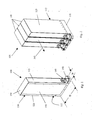
- Figure 1 depicts an example embodiment of a single dispenser 100
- Figure 2 depicts an example embodiment of three side-by-side dispensers 100 as a combination unit 105
- Dispenser 100 includes a housing 110 having a front panel 115, a back panel 117, a left panel 120, a right panel 125, a top panel 130, and a base 135.
- the left panel 120 includes a door 140 that can be opened and closed, and the top panel 130 can be opened and closed, for stocking a new stack of cutlery utensils inside the dispenser 100.
- a dispensing handle 145 and a dispensing tray 150 are disposed at the front of the dispenser 100 toward the bottom of the front panel 115 for delivering a dispensed cutlery to a user, which will be discussed in more detail below.
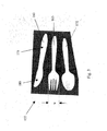
- Example cutlery utensils 155 are depicted in Figure 3 , such as a knife 160, a fork 165 and a spoon 170, which in an embodiment are made from a plastic suitable for the purposes disclosed herein.
- Each piece of cutlery 155 includes a handle portion 175 and a utility portion 180.
- each dispenser 100 may be formed as an upper unit 112, where a sliding door type runner arrangement is disposed between the upper unit 112 and the base 135 of each dispenser 100 to allow the upper unit 112 of each dispenser 100 to slide forward (see arrow 345 in Figure 2 ) to permit restocking of utensils 155 in each dispenser 100 individually via hinged side door 140 or hinged top panel 130.
- Figures 4 and 5 depict similar dispensers 100 but with different dispensing trays.
- the dispensing tray is similar to that depicted in Figures 1 and 2 , and is herein referred to by reference numeral 150.
- an alternative dispensing tray is depicted, which is herein referred to by reference numeral 152.
- Figures 4 and 5 also better illustrate the door 140 (door removed in Figure 4 ) and openable top panel 130.
- a piece of cutlery 155 is dispensed to the dispensing tray 150, 152 with its handle portion 175 being presented ahead of its utility portion 180 to an end user, best seen by referring to Figure 6 .
- dispenser 100 includes a storage area 200 for storing a stack of cutlery utensils 155 for one-at-a-time dispensing, a first zone 185 where the next-in-line utensil 155 is disposed ready to be dispensed, a second zone 190 for receiving the utensil 155 during dispensing, and a third zone 195 for delivering the dispensed utensil 155 to a user.
- the third zone 195 may herein alternatively be referred to as the dispensing tray 150, 152.
- each of the first zone 185, the second zone 190 and the third zone 195 are cooperatively adapted and configured to maintain, and present to the user, one end of the utensil 155 ahead of an opposing end of the utensil 155 during a dispensing operation, and are cooperatively adapted and configured to maintain a major axis of the utensil 155 substantially parallel with a same plane, such as the y-z plane depicted in Figure 7 , during a dispensing operation, where the length of the utensil 155 defines the direction of the major axis of the utensil 155, and where the length of the utensil 155 extends from the front panel 115 to the back panel 117 parallel to the
- the second zone 190 is offset from the first zone 185 in a first direction (negative-x-direction for example), and the third zone 195 is offset from the second zone 190 in a second direction (positive-z-direction for example) orthogonal to the first direction.
- a ramp 205 located at the second zone 190 serves to receive and direct a dispensed utensil 155 toward the third zone 195 under the influence of gravity. In this manner, a next-in-line utensil 155 to be dispensed travels in succession from the first zone 185 in the negative-x-direction toward the second zone 190, and then toward the third zone 195 in the positive-z-direction during a dispensing operation.
- the x-y-z coordinate axes depicted in Figure 7 is for discussion purposes only, and is not intended to be limiting in any way.
- a dispensing mechanism 210 is actuated from the front of the dispenser 100 for dispensing a next-in-line utensil 155 when actuated, which is best seen by now referring to Figure 8 .
- the dispensing mechanism 210 includes a driving member 215 (handle 145 having a slide plate 220 for example) operably coupled to a driven member 225 (crank arm 230 coupled to a crank 235 for example), which in turn is operably disposed to dispense a next-in-line utensil 155 upon actuation of the driving member 215 by sliding the handle 145 in the negative-y-direction.
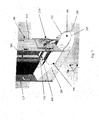
- the slide plate 220 of the handle 145 (depicted in Figure 8 ) includes a cam surface 240, depicted in Figure 9 as a slot, and the crank arm 230 of the driven member 225 includes a cam follower 245, depicted in Figures 9 and 11 as a pin, disposed in operable engagement with the slot 240.
- the pin 245 engages the slot 240.
- cam surface 240 and cam follower 245 as a means for actuating the dispensing mechanism 210
- the scope of the invention is not so limited, and also encompasses other means for actuating the dispensing mechanism 210, such as by a rack and pinion gear arrangement, a linkage arrangement, or an intermediate drive spring arrangement, for example.
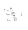
- the crank 235 includes at least one dispensing finger 250, 252 proximate the next-in-line utensil 155 that is disposed upon a platform 255 in the first zone 185.
- interaction between the cam surface (slot) 240 and the cam follower (pin) 245 causes counter-clockwise rotation of the crank 235 (as viewed from the perspective of Figure 9 ) and dispensing engagement of the at least one finger 250, 252 with the next-in-line utensil 155.
- Crank 235 is pivotally attached to the housing 110 by any means suitable for the purposes disclosed herein.
- an extension spring 260 is anchored between the crank arm 230 of the driven member 225 and the housing 110, which biases the crank 235 in a clockwise direction (as viewed from the perspective of Figure 9 ), which in turn biases the driving member 215 in the positive-y-direction via the cam surface (slot) 240 and cam follower (pin) 245 interaction.
- the driving member 215 can be said to be biased in the positive-y-direction toward a first position, a rest position, and to be actuatable in the negative-y-direction toward a second position to dispense the next-in-line utensil.
- the driven member 225 When the driving member 215 is disposed at its rest position, the driven member 225 is disposed at its respective rest position, and when the driving member 215 is disposed at the second position, the spring 260 biases both the driven member 225 and the driving member 215 toward their respective rest positions.
- extension spring 260 as a biasing means
- the invention is not limited to only the use of an extension spring, but may alternatively employ any biasing means suitable for the purposes disclosed herein, such as a torsion spring, a compression spring, a cantilevered spring, or a self-resetting dashpot, for example. Any and all biasing means suitable for the purposes disclosed herein are considered within the scope of the invention when used for the purposes disclosed herein.
- the dispensing tray 150, 152 at the third zone 195 may have more than one configuration.
- One configuration such as tray 150 for example, has an end wall 265 with an opening 270 therethrough for receiving the handle portion 175 of a dispensed utensil 155 therein during a dispensing operation.
- Another configuration such as tray 152 for example, has a closed end wall 280 for stopping the movement of utensil 155 during a dispensing operation.
- dispensing tray 150 has a necked-down side-wall profile 275 to promote transport of the handle portion 175 of utensil 155 into opening 270 during a dispensing operation.
- dispensing tray 152 has a curved profile 285 to end wall 280 to promote transport of the end of handle portion 175 of utensil 155 close to a user.
- the two tray configurations 150, 152 depicted in Figures 6 and 7 are presented in a non-limiting manner as illustrative example embodiments only. As such, other configurations for trays 150, 152 and end walls 265, 280 that meet the spirit of the purposes disclosed herein are considered within the scope of the claimed invention.
- necked-down side-wall profile 275 of dispensing tray 150 may be angled with straight lines, or contoured with curved lines, and curved profile 285 of dispensing tray 152 may have uniform curvature or non-uniform curvature, or may be angled with straight lines.
- an embodiment of the dispensing tray 152 includes a floor 290 with a pocket 295 disposed therein, which is so configured and dimensioned as to allow a user's fingers to extract a dispensed utensil 155 from the tray 152 without touching a surface of the tray floor 290 supporting the dispensed utensil 155, thereby further improving the hygiene of the cutlery dispensing system. While only one pocket 295 is depicted in Figure 13 , it will be appreciated that the scope of the invention is not so limited and also includes a floor 290 having more than one pocket 295 separated by ribs (sections of the floor between adjacent pockets) for example.
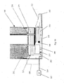
- FIG. 14 another embodiment of the invention includes a dispenser 102 having a driving member 217 with a motor 300 in operable engagement with the driven member 225 via a gear set 305.
- a microprocessor driven controller 310 is responsive to a proximity sensor 320, such as an infrared sensor responsive to the presence of a user's hand for example, for actuating the motor 300 to dispense a next-in-line utensil 155 via rotation of crank 235 and movement of fingers 250, 252 in the manner described above.
- Power for the dispenser 102 may be provided by a power line 320 connected to a source of mains AC power 325, or alternatively connected to a DC battery 330.
- a grounding path may be provided in order to discharge buildup of static electricity.
- a power/communication bus 335 may be employed to provide signal connection and communication between the various control and drive components of dispenser 102 via the several signal lines illustrated therebetween in Figure 14 .
- signal connection and communication may be provided by individual connections between the various control and drive components, thereby removing the need for a separate bus, depending on manufacturing considerations and preferences. For example, individually outsourced components with common connection configurations could be plugged into a common bus at a separate assembly facility, thereby standardizing and streamlining manufacturing processes.
- an infrared sensor as a proximity sensor 320
- the scope of the invention is not limited to only infrared sensors, and also encompasses the use of other proximity sensors suitable for the purpose disclosed herein, such as a capacitive sensor, or a manually operated switch, for example.
- proximity sensor 320 is oriented sensing outward so as to sense the presence of a user's hand requesting a utensil, which is referred to as on-demand dispensing or operating in an on-demand mode. In another embodiment, proximity sensor 320 is oriented sensing inward toward the dispensing tray 152 so as to sense the absence of a utensil 155 in the dispensing tray 152, which is referred to as missing-utensil dispensing or operating in a missing-utensil mode. In an embodiment, controller 310 is equipped with a switch 340 to enable an authorized operator of dispenser 102 to switch the setup between on-demand mode and missing-utensil mode as desired by the facility operators in which dispenser 102 is utilized.
- Switch 340 may be any kind of switch suitable for the purpose disclosed herein, such as a toggle switch, a rotary switch, or jumper wires, for example, and is not limited to only a two-position switch, but also encompasses a multi-position switch such as a three-pole switch for example, which would enable multiple dispensing modes to be activated (on-demand mode activated, missing-utensil mode activated, or both modes activated, for example).
- dispenser 100, 102 has a particular aspect ratio of width (W), along the x-direction, to depth (D), along the z-direction (with reference to Figures 1 and 7 ), that provides for a compact presence and reduced footprint on a counter top as compared to other utensil dispensers that dispense cutlery 155 sideways, that is, not with the handle portion 175 presented ahead of the utility portion 180 as described herein.
- width (W) of dispenser 100, 102 is primarily determined by the width of the first zone 185 plus the width of the second zone 190 utilized in the housing 110.
- the width (W) is equal to or less than three times the width (w) of a utensil 155 suitable for dispensing in dispenser 100, 102 (see width, w, in Figure 3 ).
- a knife 160, a fork 165 and a spoon 170 may have different overall widths (w).
- the ratio of W/w is determined by the largest utensil width (w), a fork for example, suitable for dispensing in dispenser 100, 102.
- the ratio of W/w is greater than one and equal to or less than seven.
- an embodiment of the invention may be embodied in the form of computer-implemented processes and apparatuses for practicing those processes.
- the present invention may also be embodied in the form of a computer program product having computer program code containing instructions embodied in tangible media, such as floppy diskettes, CD-ROMs, hard drives, USB (universal serial bus) drives, or any other computer readable storage medium, such as random access memory (RAM), read only memory (ROM), erasable programmable read only memory (EPROM), electrically erasable programmable read only memory (EEPROM), or flash memory, for example, wherein, when the computer program code is loaded into and executed by a computer/controller, the computer/controller becomes an apparatus for practicing the invention.
- RAM random access memory
- ROM read only memory
- EPROM erasable programmable read only memory
- EEPROM electrically erasable programmable read only memory
- flash memory for example, wherein, when the computer program code is loaded into and executed by a computer/controller,
- the present invention may also be embodied in the form of computer program code, for example, whether stored in a storage medium, loaded into and/or executed by a computer/controller, or transmitted over some transmission medium, such as over electrical wiring or cabling, through fiber optics, or via electromagnetic radiation, wherein when the computer program code is loaded into and executed by a computer/controller, the computer/controller becomes an apparatus for practicing the invention.
- the computer program code segments configure the microprocessor to create specific logic circuits.
- a technical effect of the executable instructions is to dispense cutlery utensils via an on-demand mode or a missing-utensil mode in an improved hygienic manner.
- a first embodiment of the invention includes a cutlery utensil dispenser having a housing that includes a first zone for holding a utensil to be dispensed, a second zone for receiving the utensil during dispensing, and a third zone for delivering the dispensed utensil to a user.
- the first, second and third zones are cooperatively configured and adapted to maintain, and present to the user, one end of the utensil ahead of an opposing end of the utensil during a dispensing operation.
- a second embodiment of the invention includes a cutlery utensil dispenser according to the first embodiment, wherein each of the first zone, the second zone and the third zone are adapted and configured to maintain a major axis of the utensil substantially parallel with a same plane, the second zone being offset from the first zone in a first direction, and the third zone being offset from the second zone in a second direction orthogonal to the first direction.
- a third embodiment of the invention includes a cutlery dispenser according to any of the first and second embodiments, wherein a next-in-line utensil to be dispensed passes in succession from the first zone to the second zone to the third zone during a dispensing operation.
- a fourth embodiment of the invention includes a cutlery dispenser according to any of the first through third embodiments, wherein the third zone is adapted and configured to present a handle portion of the utensil to the user ahead of a utility portion of the utensil.
- a fifth embodiment of the invention includes a cutlery dispenser according to any of the first through fourth embodiments, wherein the second zone includes a ramp configured and disposed to dispense the utensil toward the third zone under the influence of gravity.
- a sixth embodiment of the invention includes a cutlery dispenser according to any of the first through fifth embodiments, further including a dispensing mechanism having a driving member operably coupled to a driven member, the driven member being operably disposed to dispense a next-in-line utensil upon actuation of the driving member.
- a seventh embodiment of the invention includes a cutlery dispenser according to the sixth embodiment, wherein the driving member includes a manually actuatable handle, the driven member includes a crank having a crank arm coupled to the handle, and in response to actuation of the handle, the crank is actuated via the crank arm to dispense the next-in-line utensil.
- An eighth embodiment of the invention includes a cutlery dispenser according to the seventh embodiment, wherein the handle includes a cam surface, the crank arm includes a cam follower disposed in operable engagement with the cam surface, the crank includes at least one dispensing finger proximate the next-in-line utensil, and in response to translation actuation of the handle, interaction between the cam surface and the cam follower causes rotation of the crank and dispensing engagement of the at least one finger with the next-in-line utensil.
- a ninth embodiment of the invention includes a cutlery dispenser according to the eighth embodiment, wherein the cam surface includes a slot, and the cam follower includes a pin.
- a tenth embodiment of the invention includes a cutlery dispenser according to any of the sixth through ninth embodiments, wherein the driving member is biased toward a first position, a rest position, and is actuatable toward a second position to dispense the next-in-line utensil, and in response to the driving member being disposed at its rest position, the driven member is disposed at its respective rest position.
- An eleventh embodiment of the invention includes a cutlery dispenser according to the tenth embodiment, further including a spring disposed to bias the driving member toward its rest position, and in response to the driving member being disposed at the second position, the spring biases the driving member toward its rest position and in response thereto, the driving member biases the driven member to its respective rest position.
- a twelfth embodiment of the invention includes a cutlery dispenser according to the fourth embodiment, wherein the third zone includes a dispensing tray having an end wall with an opening therethrough for receiving the handle portion of the dispensed utensil therein.
- a thirteenth embodiment of the invention includes a cutlery dispenser according to the fourth embodiment, wherein the third zone includes a dispensing tray having a solid end wall for stopping the handle portion of the dispensed utensil.
- a fourteenth embodiment of the invention includes a cutlery dispenser according to the thirteenth embodiment, wherein the dispensing tray includes a pocket floor being so configured and dimensioned as to allow a user's fingers to extract a dispensed utensil from the tray without touching a surface of the tray floor supporting the dispensed utensil.
- a fifteenth embodiment of the invention includes a cutlery dispenser according to any of the sixth through eleventh embodiments, wherein the dispensing mechanism includes a motor in operable engagement with the driving member, and a switch for actuating the motor in response to a demand for a utensil.
- a sixteenth embodiment of the invention includes a cutlery dispenser according to the fifteenth embodiment, wherein the switch includes an infrared sensor.
- a seventeenth embodiment of the invention includes a cutlery dispenser according to any of the sixth through eleventh embodiments, wherein the dispensing mechanism includes a motor in operable engagement with the driving member, and a switch for actuating the motor in response to an absence of a utensil in the third zone.
- An eighteenth embodiment of the invention includes a cutlery dispenser according to the seventeenth embodiment, wherein the switch includes an infrared sensor.
- a nineteenth embodiment of the invention includes a cutlery dispenser according to any of the first through eighteenth embodiments, wherein the first zone and the second zone define a width of the housing that is equal to or less than three times the width of the utensil.
Landscapes
- Physics & Mathematics (AREA)
- General Physics & Mathematics (AREA)
- Table Equipment (AREA)
Description
- The present invention relates to a cutlery utensil dispenser according to the preamble of claim 1. A generic dispenser is for instance known from
EP 1719438 A1 . Said document discloses a cutlery dispensing mechanism in which the cutlery is dispensed in a sidewise direction. Further dispenser where cutlery is dispensed in a sidewise direction is known fromWO2008/058187 A2 andWO 01/68492 A1 WO 2004/028309 ,US 2004/0089670 A1 andUS 2149099 A1 . - The present disclosure relates generally to a cutlery utensil dispenser, and particularly to a compact cutlery utensil dispenser that presents the handle of the dispensed cutlery to a user.
- Eating facilities often provide cutlery utensils in dispensing bins, where all customers place their hands into the bins in order to retrieve a knife, fork, spoon or spork. While such arrangements provide for economical dispensing of cutlery utensils, as opposed to sets of utensils being separately wrapped in plastic sleeves, the open air bins are not very hygienic, and can spread hand-carried bacteria and the like to other utensils in the bin or potentially to another customer.
- In an attempt to address concerns relating to the dispensing of hygienic cutlery utensils, enclosed dispensers have been employed where a stack of cutlery utensils are placed in a utensil compartment and dispensed one at a time on command by operation of a dispensing lever. Such arrangements may be suitable for their intended purpose, but are also bulky and occupy valuable counter top space needed for other purposes. One remedy to such a deficiency may be to simply move the dispenser to a counter top in an area seeing less traffic. However, such a dispenser would defeat the purpose of being conveniently located. In view of these and other deficiencies, there is a need in the art for an improved cutlery utensil dispenser.
- This background information is provided to reveal information believed by the applicant to be of possible relevance to the present invention. No admission is necessarily intended, nor should be construed, that any of the preceding information constitutes prior art against the present invention.
- In view of the dispenser known from
EP1719438 A1 , it is an object of the present invention to provide an improved actuating mechanism. - The aforesaid problem is solved with a cutlery utensil dispenser defined in claim 1. Further preferred embodiments are defined in the dependent claims.
- An embodiment of the invention includes a cutlery utensil dispenser having a housing that includes a first zone for holding a utensil to be dispensed, a second zone for receiving the utensil during dispensing, and a third zone for delivering the dispensed utensil to a user. The first, second and third zones are cooperatively configured and adapted to maintain, and present to the user, one end of the utensil ahead of an opposing end of the utensil during a dispensing operation.
- Referring to the exemplary drawings wherein like elements are numbered alike in the accompanying Figures:
-
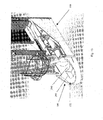
Figure 1 depicts in left side isometric view an example single dispenser in accordance with an embodiment of the invention; -
Figure 2 depicts in right side isometric view an example three-gang dispenser in accordance with an embodiment of the invention; -
Figure 3 depicts in plan view example cutlery utensils for use in accordance with an embodiment of the invention; -
Figures 4 and 5 depict in left side isometric view example dispensers in accordance with an embodiment of the invention; -
Figure 6 depicts in left side isometric view a portion of an example dispenser in accordance with an embodiment of the invention; -
Figure 7 depicts in left side isometric view portions of an example dispenser in accordance with an embodiment of the invention; -
Figure 8 depicts in right side isometric view portion of an example dispenser in accordance with an embodiment of the invention; -
Figure 9 depicts in front view portions of an example dispenser showing portions of the operating mechanism in accordance with an embodiment of the invention; -
Figure 10 depicts in bottom isometric view portions of an example dispenser showing portions of the operating mechanism in accordance with an embodiment of the invention; -
Figure 11 depicts in left side isometric view portions of an example dispenser showing portions of the operating mechanism in accordance with an embodiment of the invention; -
Figure 12 depicts in isometric view a crank for use in a dispenser in accordance with an embodiment of the invention; -
Figure 13 depicts in right side isometric view the dispenser ofFigure 8 having an alternative dispensing tray in accordance with an embodiment of the invention; and -
Figure 14 depicts in left side view a motorized dispenser in accordance with an embodiment of the invention. - Although the following detailed description contains many specifics for the purposes of illustration, anyone of ordinary skill in the art will appreciate that many variations and alterations to the following details are within the scope of the invention. Accordingly, the following preferred embodiments of the invention are set forth without any loss of generality to, and without imposing limitations upon, the claimed invention.
- An embodiment of the invention, as shown and described by the various figures and accompanying text, provides a compact cutlery utensil dispenser that presents the handle of the dispensed cutlery to the user, thereby reducing the likelihood of the utility portion of the dispensed cutlery being touching by another person, which serves to improve the overall hygiene of the cutlery dispensing process. While embodiments described herein depict the dispensing of a knife as an example piece of cutlery, it will be appreciated that the disclosed invention is also applicable to other types of cutlery, such as a fork, spoon, or spork (combination of spoon and fork in one utensil), for example.
-
Figure 1 depicts an example embodiment of asingle dispenser 100, andFigure 2 depicts an example embodiment of three side-by-side dispensers 100 as acombination unit 105.Dispenser 100 includes ahousing 110 having afront panel 115, aback panel 117, aleft panel 120, aright panel 125, atop panel 130, and abase 135. In an embodiment, theleft panel 120 includes adoor 140 that can be opened and closed, and thetop panel 130 can be opened and closed, for stocking a new stack of cutlery utensils inside thedispenser 100. Adispensing handle 145 and a dispensingtray 150 are disposed at the front of thedispenser 100 toward the bottom of thefront panel 115 for delivering a dispensed cutlery to a user, which will be discussed in more detail below. Examplecutlery utensils 155 are depicted inFigure 3 , such as aknife 160, afork 165 and aspoon 170, which in an embodiment are made from a plastic suitable for the purposes disclosed herein. Each piece ofcutlery 155 includes ahandle portion 175 and autility portion 180. - In an embodiment where it is desirable to permanently secure
dispenser 100 to a support surface such as a cafeteria counter top, everything but thebase 135 of eachdispenser 100 may be formed as anupper unit 112, where a sliding door type runner arrangement is disposed between theupper unit 112 and thebase 135 of eachdispenser 100 to allow theupper unit 112 of eachdispenser 100 to slide forward (seearrow 345 inFigure 2 ) to permit restocking ofutensils 155 in eachdispenser 100 individually viahinged side door 140 or hingedtop panel 130. While an embodiment has been disclosed having anupper unit 112 capable of being slid forward from thebase 135 for restocking, it will be appreciated that the scope of the invention is not limited to only a forward sliding action, but also encompasses other means of accessing the interior ofdispenser 100, such as for example, by lifting theupper unit 112 off of thebase 135, rotating theupper unit 112 with respect to thebase 135 in any suitable direction about any suitable pivot axis, or by translating theupper unit 112 with respect to thebase 135 in any suitable direction, for the purpose of restocking. -
Figures 4 and 5 depictsimilar dispensers 100 but with different dispensing trays. InFigure 4 , the dispensing tray is similar to that depicted inFigures 1 and 2 , and is herein referred to byreference numeral 150. InFigure 5 , an alternative dispensing tray is depicted, which is herein referred to byreference numeral 152.Figures 4 and 5 also better illustrate the door 140 (door removed inFigure 4 ) andopenable top panel 130. By depressing thehandle 145 in a manner to be discussed below, a piece ofcutlery 155 is dispensed to the dispensingtray handle portion 175 being presented ahead of itsutility portion 180 to an end user, best seen by referring toFigure 6 . - Referring now to
Figure 7 ,dispenser 100 includes astorage area 200 for storing a stack ofcutlery utensils 155 for one-at-a-time dispensing, afirst zone 185 where the next-in-line utensil 155 is disposed ready to be dispensed, asecond zone 190 for receiving theutensil 155 during dispensing, and athird zone 195 for delivering the dispensedutensil 155 to a user. Thethird zone 195 may herein alternatively be referred to as the dispensingtray - As will be appreciated by the size and configuration of the
dispenser 100 disclosed herein, the stacking arrangement of a stack ofcutlery 155 in thehousing 110 of thedispenser 100, and the presentation of thehandle portion 175 of a dispensedutensil 155 to a user, each of thefirst zone 185, thesecond zone 190 and thethird zone 195 are cooperatively adapted and configured to maintain, and present to the user, one end of theutensil 155 ahead of an opposing end of theutensil 155 during a dispensing operation, and are cooperatively adapted and configured to maintain a major axis of theutensil 155 substantially parallel with a same plane, such as the y-z plane depicted inFigure 7 , during a dispensing operation, where the length of theutensil 155 defines the direction of the major axis of theutensil 155, and where the length of theutensil 155 extends from thefront panel 115 to theback panel 117 parallel to the z-axis for example (seen by referring to the orientation ofutensil 155 infirst zone 185 inFigure 7 ). - As illustrated, the
second zone 190 is offset from thefirst zone 185 in a first direction (negative-x-direction for example), and thethird zone 195 is offset from thesecond zone 190 in a second direction (positive-z-direction for example) orthogonal to the first direction. Aramp 205 located at thesecond zone 190 serves to receive and direct a dispensedutensil 155 toward thethird zone 195 under the influence of gravity. In this manner, a next-in-line utensil 155 to be dispensed travels in succession from thefirst zone 185 in the negative-x-direction toward thesecond zone 190, and then toward thethird zone 195 in the positive-z-direction during a dispensing operation. The x-y-z coordinate axes depicted inFigure 7 is for discussion purposes only, and is not intended to be limiting in any way. - A
dispensing mechanism 210 is actuated from the front of thedispenser 100 for dispensing a next-in-line utensil 155 when actuated, which is best seen by now referring toFigure 8 . In an embodiment, thedispensing mechanism 210 includes a driving member 215 (handle 145 having aslide plate 220 for example) operably coupled to a driven member 225 (crank arm 230 coupled to acrank 235 for example), which in turn is operably disposed to dispense a next-in-line utensil 155 upon actuation of the drivingmember 215 by sliding thehandle 145 in the negative-y-direction. - Referring now to
Figure 9 , theslide plate 220 of the handle 145 (depicted inFigure 8 ) includes acam surface 240, depicted inFigure 9 as a slot, and thecrank arm 230 of the drivenmember 225 includes acam follower 245, depicted inFigures 9 and11 as a pin, disposed in operable engagement with theslot 240. In the embodiment depicted, thepin 245 engages theslot 240. While an embodiment has been disclosed having acam surface 240 andcam follower 245 as a means for actuating thedispensing mechanism 210, it will be appreciated that the scope of the invention is not so limited, and also encompasses other means for actuating thedispensing mechanism 210, such as by a rack and pinion gear arrangement, a linkage arrangement, or an intermediate drive spring arrangement, for example. - Referring to
Figures 8-12 collectively, thecrank 235 includes at least one dispensingfinger line utensil 155 that is disposed upon aplatform 255 in thefirst zone 185. In response to translation actuation of thehandle 145 in the negative-y-direction, interaction between the cam surface (slot) 240 and the cam follower (pin) 245 causes counter-clockwise rotation of the crank 235 (as viewed from the perspective ofFigure 9 ) and dispensing engagement of the at least onefinger line utensil 155.Crank 235 is pivotally attached to thehousing 110 by any means suitable for the purposes disclosed herein. - With reference primarily to
Figure 9 , an extension spring 260 is anchored between thecrank arm 230 of the drivenmember 225 and thehousing 110, which biases thecrank 235 in a clockwise direction (as viewed from the perspective ofFigure 9 ), which in turn biases the drivingmember 215 in the positive-y-direction via the cam surface (slot) 240 and cam follower (pin) 245 interaction. As such, the drivingmember 215 can be said to be biased in the positive-y-direction toward a first position, a rest position, and to be actuatable in the negative-y-direction toward a second position to dispense the next-in-line utensil. When the drivingmember 215 is disposed at its rest position, the drivenmember 225 is disposed at its respective rest position, and when the drivingmember 215 is disposed at the second position, the spring 260 biases both the drivenmember 225 and the drivingmember 215 toward their respective rest positions. - While embodiments depicted herein utilize an extension spring 260 as a biasing means, it will be appreciated that the invention is not limited to only the use of an extension spring, but may alternatively employ any biasing means suitable for the purposes disclosed herein, such as a torsion spring, a compression spring, a cantilevered spring, or a self-resetting dashpot, for example. Any and all biasing means suitable for the purposes disclosed herein are considered within the scope of the invention when used for the purposes disclosed herein.
- As discussed above and with reference now to
Figures 6 and7 , the dispensingtray third zone 195 may have more than one configuration. One configuration, such astray 150 for example, has anend wall 265 with anopening 270 therethrough for receiving thehandle portion 175 of a dispensedutensil 155 therein during a dispensing operation. Another configuration, such astray 152 for example, has aclosed end wall 280 for stopping the movement ofutensil 155 during a dispensing operation. In the embodiment depicted inFigure 6 , dispensingtray 150 has a necked-down side-wall profile 275 to promote transport of thehandle portion 175 ofutensil 155 intoopening 270 during a dispensing operation. In the embodiment depicted inFigure 7 , dispensingtray 152 has acurved profile 285 to endwall 280 to promote transport of the end ofhandle portion 175 ofutensil 155 close to a user. The twotray configurations Figures 6 and7 are presented in a non-limiting manner as illustrative example embodiments only. As such, other configurations fortrays walls wall profile 275 of dispensingtray 150 may be angled with straight lines, or contoured with curved lines, andcurved profile 285 of dispensingtray 152 may have uniform curvature or non-uniform curvature, or may be angled with straight lines. - Referring now to
Figure 13 , an embodiment of the dispensingtray 152 includes afloor 290 with apocket 295 disposed therein, which is so configured and dimensioned as to allow a user's fingers to extract a dispensedutensil 155 from thetray 152 without touching a surface of thetray floor 290 supporting the dispensedutensil 155, thereby further improving the hygiene of the cutlery dispensing system. While only onepocket 295 is depicted inFigure 13 , it will be appreciated that the scope of the invention is not so limited and also includes afloor 290 having more than onepocket 295 separated by ribs (sections of the floor between adjacent pockets) for example. - Referring now to
Figure 14 , another embodiment of the invention includes adispenser 102 having a drivingmember 217 with amotor 300 in operable engagement with the drivenmember 225 via agear set 305. In an embodiment, a microprocessor drivencontroller 310 is responsive to aproximity sensor 320, such as an infrared sensor responsive to the presence of a user's hand for example, for actuating themotor 300 to dispense a next-in-line utensil 155 via rotation of crank 235 and movement offingers dispenser 102 may be provided by apower line 320 connected to a source ofmains AC power 325, or alternatively connected to aDC battery 330. In an embodiment employing aDC battery 330, a grounding path may be provided in order to discharge buildup of static electricity. A power/communication bus 335 may be employed to provide signal connection and communication between the various control and drive components ofdispenser 102 via the several signal lines illustrated therebetween inFigure 14 . Alternatively, signal connection and communication may be provided by individual connections between the various control and drive components, thereby removing the need for a separate bus, depending on manufacturing considerations and preferences. For example, individually outsourced components with common connection configurations could be plugged into a common bus at a separate assembly facility, thereby standardizing and streamlining manufacturing processes. While an embodiment has been disclosed having an infrared sensor as aproximity sensor 320, it will be appreciated that the scope of the invention is not limited to only infrared sensors, and also encompasses the use of other proximity sensors suitable for the purpose disclosed herein, such as a capacitive sensor, or a manually operated switch, for example. - Comparing the manually driven
dispenser 100 ofFigures 1-13 with the motor drivendispenser 102 ofFigure 14 , it will be appreciated that all of the foregoing description of operation is applicable to themanual dispenser 100 and the motor drivendispenser 102 alike with the exception of the means for actuating a dispensing operation. - In an embodiment,
proximity sensor 320 is oriented sensing outward so as to sense the presence of a user's hand requesting a utensil, which is referred to as on-demand dispensing or operating in an on-demand mode. In another embodiment,proximity sensor 320 is oriented sensing inward toward the dispensingtray 152 so as to sense the absence of autensil 155 in the dispensingtray 152, which is referred to as missing-utensil dispensing or operating in a missing-utensil mode. In an embodiment,controller 310 is equipped with aswitch 340 to enable an authorized operator ofdispenser 102 to switch the setup between on-demand mode and missing-utensil mode as desired by the facility operators in which dispenser 102 is utilized.Switch 340 may be any kind of switch suitable for the purpose disclosed herein, such as a toggle switch, a rotary switch, or jumper wires, for example, and is not limited to only a two-position switch, but also encompasses a multi-position switch such as a three-pole switch for example, which would enable multiple dispensing modes to be activated (on-demand mode activated, missing-utensil mode activated, or both modes activated, for example). - In illustrated in the various figures,
dispenser Figures 1 and7 ), that provides for a compact presence and reduced footprint on a counter top as compared to other utensil dispensers that dispensecutlery 155 sideways, that is, not with thehandle portion 175 presented ahead of theutility portion 180 as described herein. From the foregoing description, it will be appreciated that the width (W) ofdispenser first zone 185 plus the width of thesecond zone 190 utilized in thehousing 110. In an embodiment, the width (W) is equal to or less than three times the width (w) of autensil 155 suitable for dispensing indispenser 100, 102 (see width, w, inFigure 3 ). As can be seen by reference toFigure 3 , aknife 160, afork 165 and aspoon 170, may have different overall widths (w). Thus, the ratio of W/w is determined by the largest utensil width (w), a fork for example, suitable for dispensing indispenser - In view of
dispenser 102 having acontroller 310, it will be appreciated that an embodiment of the invention may be embodied in the form of computer-implemented processes and apparatuses for practicing those processes. The present invention may also be embodied in the form of a computer program product having computer program code containing instructions embodied in tangible media, such as floppy diskettes, CD-ROMs, hard drives, USB (universal serial bus) drives, or any other computer readable storage medium, such as random access memory (RAM), read only memory (ROM), erasable programmable read only memory (EPROM), electrically erasable programmable read only memory (EEPROM), or flash memory, for example, wherein, when the computer program code is loaded into and executed by a computer/controller, the computer/controller becomes an apparatus for practicing the invention. The present invention may also be embodied in the form of computer program code, for example, whether stored in a storage medium, loaded into and/or executed by a computer/controller, or transmitted over some transmission medium, such as over electrical wiring or cabling, through fiber optics, or via electromagnetic radiation, wherein when the computer program code is loaded into and executed by a computer/controller, the computer/controller becomes an apparatus for practicing the invention. When implemented on a general-purpose microprocessor, the computer program code segments configure the microprocessor to create specific logic circuits. A technical effect of the executable instructions is to dispense cutlery utensils via an on-demand mode or a missing-utensil mode in an improved hygienic manner. - The particular and innovative arrangement of components according to the invention therefore affords numerous not insignificant technical advantages in addition to an entirely novel and attractive visual appearance.
- In view of the foregoing, it will be appreciated that at least nineteen embodiments of the invention in various combinations fall within the ambit of the disclosed invention, and are summarized below. It will also be appreciated that other embodiments of the invention involving other combinations not specifically summarized below may also fall within the ambit of the disclosed invention.
- A first embodiment of the invention includes a cutlery utensil dispenser having a housing that includes a first zone for holding a utensil to be dispensed, a second zone for receiving the utensil during dispensing, and a third zone for delivering the dispensed utensil to a user. The first, second and third zones are cooperatively configured and adapted to maintain, and present to the user, one end of the utensil ahead of an opposing end of the utensil during a dispensing operation.
- A second embodiment of the invention includes a cutlery utensil dispenser according to the first embodiment, wherein each of the first zone, the second zone and the third zone are adapted and configured to maintain a major axis of the utensil substantially parallel with a same plane, the second zone being offset from the first zone in a first direction, and the third zone being offset from the second zone in a second direction orthogonal to the first direction.
- A third embodiment of the invention includes a cutlery dispenser according to any of the first and second embodiments, wherein a next-in-line utensil to be dispensed passes in succession from the first zone to the second zone to the third zone during a dispensing operation.
- A fourth embodiment of the invention includes a cutlery dispenser according to any of the first through third embodiments, wherein the third zone is adapted and configured to present a handle portion of the utensil to the user ahead of a utility portion of the utensil.
- A fifth embodiment of the invention includes a cutlery dispenser according to any of the first through fourth embodiments, wherein the second zone includes a ramp configured and disposed to dispense the utensil toward the third zone under the influence of gravity.
- A sixth embodiment of the invention includes a cutlery dispenser according to any of the first through fifth embodiments, further including a dispensing mechanism having a driving member operably coupled to a driven member, the driven member being operably disposed to dispense a next-in-line utensil upon actuation of the driving member.
- A seventh embodiment of the invention includes a cutlery dispenser according to the sixth embodiment, wherein the driving member includes a manually actuatable handle, the driven member includes a crank having a crank arm coupled to the handle, and in response to actuation of the handle, the crank is actuated via the crank arm to dispense the next-in-line utensil.
- An eighth embodiment of the invention includes a cutlery dispenser according to the seventh embodiment, wherein the handle includes a cam surface, the crank arm includes a cam follower disposed in operable engagement with the cam surface, the crank includes at least one dispensing finger proximate the next-in-line utensil, and in response to translation actuation of the handle, interaction between the cam surface and the cam follower causes rotation of the crank and dispensing engagement of the at least one finger with the next-in-line utensil.
- A ninth embodiment of the invention includes a cutlery dispenser according to the eighth embodiment, wherein the cam surface includes a slot, and the cam follower includes a pin.
- A tenth embodiment of the invention includes a cutlery dispenser according to any of the sixth through ninth embodiments, wherein the driving member is biased toward a first position, a rest position, and is actuatable toward a second position to dispense the next-in-line utensil, and in response to the driving member being disposed at its rest position, the driven member is disposed at its respective rest position.
- An eleventh embodiment of the invention includes a cutlery dispenser according to the tenth embodiment, further including a spring disposed to bias the driving member toward its rest position, and in response to the driving member being disposed at the second position, the spring biases the driving member toward its rest position and in response thereto, the driving member biases the driven member to its respective rest position.
- A twelfth embodiment of the invention includes a cutlery dispenser according to the fourth embodiment, wherein the third zone includes a dispensing tray having an end wall with an opening therethrough for receiving the handle portion of the dispensed utensil therein.
- A thirteenth embodiment of the invention includes a cutlery dispenser according to the fourth embodiment, wherein the third zone includes a dispensing tray having a solid end wall for stopping the handle portion of the dispensed utensil.
- A fourteenth embodiment of the invention includes a cutlery dispenser according to the thirteenth embodiment, wherein the dispensing tray includes a pocket floor being so configured and dimensioned as to allow a user's fingers to extract a dispensed utensil from the tray without touching a surface of the tray floor supporting the dispensed utensil.
- A fifteenth embodiment of the invention includes a cutlery dispenser according to any of the sixth through eleventh embodiments, wherein the dispensing mechanism includes a motor in operable engagement with the driving member, and a switch for actuating the motor in response to a demand for a utensil.
- A sixteenth embodiment of the invention includes a cutlery dispenser according to the fifteenth embodiment, wherein the switch includes an infrared sensor.
- A seventeenth embodiment of the invention includes a cutlery dispenser according to any of the sixth through eleventh embodiments, wherein the dispensing mechanism includes a motor in operable engagement with the driving member, and a switch for actuating the motor in response to an absence of a utensil in the third zone.
- An eighteenth embodiment of the invention includes a cutlery dispenser according to the seventeenth embodiment, wherein the switch includes an infrared sensor.
- A nineteenth embodiment of the invention includes a cutlery dispenser according to any of the first through eighteenth embodiments, wherein the first zone and the second zone define a width of the housing that is equal to or less than three times the width of the utensil.
- While the invention has been described with reference to exemplary embodiments, it will be understood by those skilled in the art that various changes may be made and equivalents may be substituted for elements thereof without departing from the scope of the claims. Therefore, it is intended that the invention not be limited to the particular embodiment disclosed as the best or only mode contemplated for carrying out this invention, but that the invention will include all embodiments falling within the scope of the appended claims. Also, in the drawings and the description, there have been disclosed exemplary embodiments of the invention and, although specific terms may have been employed, they are unless otherwise stated used in a generic and descriptive sense only and not for purposes of limitation, the scope of the invention therefore not being so limited. Moreover, the use of the terms first, second, etc. do not denote any order or importance, but rather the terms first, second, etc. are used to distinguish one element from another. Furthermore, the use of the terms a, an, etc. do not denote a limitation of quantity, but rather denote the presence of at least one of the referenced item.
Claims (17)
- A cutlery utensil dispenser (100), comprising:a housing (110) comprisinga first zone (185) for holding a utensil (155) to be dispensed,a second zone (190) for receiving the utensil during dispensing,a third zone (195) for delivering the dispensed utensil to a user;and a dispensing mechanism comprising a driving member (215) operably coupled to a driven member (225);wherein the first, second and third zones being cooperatively configured and adapted to maintain, and present to the user, one end (175) of the utensil ahead of an opposing end (180) of the utensil during a dispensing operation;wherein the driven member (215) being operably disposed to dispense a next-in-line utensil upon actuation of the driving member (215);wherein the driving member (215) comprises a manually actuatable handle (145); the driven member comprises a crank (235) comprising a crank arm (230) coupled to the handle (145); andwherein in response to actuation of the handle (145), the crank (235) is actuated via the crank arm (230) to dispense the next-in-line utensil
characterized in thatthe handle (145) comprises a cam surface (240);the crank arm (230) comprises a cam follower (245) disposed in operable engagement with the cam surface (240);the crank (235) comprises at least one dispensing finger (250, 252) proximate the next-in-line utensil; andin response to translation actuation of the handle (145), interaction between the cam surface (240) and the cam follower (245) causes rotation of the crank (235) and dispensing engagement of the at least one finger with the next-in-line utensil. - The cutlery dispenser of Claim 1, wherein;
each of the first zone (185), the second zone (190) and the third zone (195) are adapted and configured to maintain a longitudinal axis of the utensil substantially parallel with a y-z plane in relation to a set of orthogonal x-y-z axes;
the third zone (195) being offset from the second zone (190) in a second direction defined by a positive-z direction orthogonal to the first direction,
and the second zone (190) being offset from the first zone (185) in a first direction defined by a negative-x direction. - The cutlery dispenser of Claims 1 or 2, wherein:a next-in-line utensil to be dispensed passes in succession from the first zone (185) to the second zone (190) to the third zone (195) during a dispensing operation.
- The dispenser of one of the preceding claims, wherein the third zone (195) is adapted and configured to present a handle portion (175) of the utensil to the user ahead of a utility portion (180) of the utensil.
- The dispenser of one of the preceding claims, wherein the second zone (190) comprises a ramp configured and disposed to dispense the utensil toward the third zone (195) under the influence of gravity.
- The dispenser of one of the preceding claims, wherein:the cam surface comprises a slot; andthe cam follower comprises a pin.
- The dispenser of of one of the preceding claims, wherein:the driving member (215) is biased toward a first position, a rest position, and is actuatable toward a second position to dispense the next-in-line utensil; andin response to the driving member (215) being disposed at its rest position, the driven member (225) is disposed at its respective rest position.
- The dispenser of Claim 8, further comprising:a spring (260) disposed to bias the driving member (215) toward its rest position; andin response to the driving member being disposed at the second position, the spring (260) biases the driving member toward its rest position and in response thereto, the driving member biases the driven member (225) to its respective rest position.
- The dispenser of Claim 4, wherein:the third zone (195) comprises a dispensing tray (150) comprising an end wall (265) with an opening (270) therethrough for receiving the handle portion of the dispensed utensil therein.
- The dispenser of Claim 4, wherein:the third zone (195) comprises a dispensing tray (152) comprising a solid end wall (280) for stopping the handle portion of the dispensed utensil.
- The dispenser of Claim 10, wherein:the dispensing tray comprises a pocket floor being so configured and dimensioned as to allow a user's fingers to extract a dispensed utensil from the tray without touching a surface of the tray floor supporting the dispensed utensil.
- The dispenser of Claim 1, wherein:the dispensing mechanism comprises a motor (300) in operable engagement with the driving member (215); anda switch (340) for actuating the motor in response to an absence of a utensil in the third zone (195).
- The dispenser of Claim 12, wherein:the switch (340) comprises an infrared sensor (320).
- The cutlery dispenser of one of the preceding claims, wherein:the first zone (185) and the second zone (190) define a width of the housing that is equal to or less than three times the width of the utensil.
- The cutlery dispenser of Claim 1, wherein:the third zone (195) comprises a dispensing tray (150, 152) comprising at least one of a side-wall profile or an end-wall profile configured to present the one end of the utensil to the user ahead of the opposing end, configured to maintain the one end oriented for presentation to the user, and configured to maintain the major axis of the utensil substantially parallel with the y-z plane.
- The cutlery dispenser of Claim 4, wherein:the third zone (195) comprises a dispensing tray (150, 152) comprising at least one of a side-wall profile or an end-wall profile configured to present the handle portion (175) of the utensil to the user ahead of the utility portion (180), configured to maintain the handle portion oriented for presentation to the user, and configured to maintain the major axis of the utensil substantially parallel with the y-z plane.
- The dispenser of Claim 16, wherein:the dispensing tray (150) comprises an end wall (265) with an opening (270) therethrough for receiving the handle portion of the dispensed utensil therein.
Applications Claiming Priority (1)
| Application Number | Priority Date | Filing Date | Title |
|---|---|---|---|
| US31556110P | 2010-03-19 | 2010-03-19 |
Publications (2)
| Publication Number | Publication Date |
|---|---|
| EP2366313A1 EP2366313A1 (en) | 2011-09-21 |
| EP2366313B1 true EP2366313B1 (en) | 2015-12-16 |
Family
ID=43825316
Family Applications (1)
| Application Number | Title | Priority Date | Filing Date |
|---|---|---|---|
| EP11158661.6A Not-in-force EP2366313B1 (en) | 2010-03-19 | 2011-03-17 | Cutlery utensil dispenser |
Country Status (3)
| Country | Link |
|---|---|
| US (1) | US9295344B2 (en) |
| EP (1) | EP2366313B1 (en) |
| ES (1) | ES2559184T3 (en) |
Families Citing this family (39)
| Publication number | Priority date | Publication date | Assignee | Title |
|---|---|---|---|---|
| US8210364B2 (en) | 2005-05-05 | 2012-07-03 | Dixie Consumer Products Llc | Dispenser for disposable cutlery and components therefor |
| US9237815B2 (en) | 2006-11-07 | 2016-01-19 | Dixie Consumer Products Llc | Cutlery dispenser and method of dispensing cutlery |
| AU2007316386A1 (en) * | 2006-11-07 | 2008-05-15 | Dixie Consumer Products Llc | Cutlery dispenser and method of dispensing cutlery |
| US8701932B2 (en) * | 2008-10-08 | 2014-04-22 | Dixie Consumer Products Llc | Cutlery dispenser trays |
| US8360273B2 (en) * | 2008-10-08 | 2013-01-29 | Dixie Consumer Products Llc | Cutlery utensil dispenser |
| US9295344B2 (en) * | 2010-03-19 | 2016-03-29 | Dixie Consumer Products Llc | Cutlery utensil dispenser |
| MX2012014401A (en) | 2010-06-08 | 2013-02-27 | Dixie Consumer Products Llc | SYSTEM AND METHOD FOR HOLDING OR MAINTAINING COVER BOARD. |
| US11083316B1 (en) | 2010-07-07 | 2021-08-10 | Waddington North America, Inc. | Recyclable and dispensable cutlery utensil |
| US8839522B2 (en) | 2010-08-12 | 2014-09-23 | Dixie Consumer Products Llc | Interlocking cutlery and related methods |
| MX2013001725A (en) | 2010-08-24 | 2013-10-28 | Dixie Consumer Products Llc | Removable strip for packaging cutlery and related methods. |
| CN103249332B (en) | 2010-12-10 | 2016-11-16 | 迪克西消费产品有限公司 | Dispensing mechanism for appliance dispenser and related method |
| US10898010B2 (en) | 2010-12-10 | 2021-01-26 | Gpcp Ip Holdings Llc | Screw drive for dispensing cutlery and related methods |
| MX353821B (en) | 2010-12-14 | 2018-01-31 | Gpcp Ip Holdings Llc | Belt drive for dispensing cutlery and related methods. |
| US9439518B2 (en) | 2011-08-19 | 2016-09-13 | Dixie Consumer Products Llc | Cutlery dispenser |
| US9049948B2 (en) | 2012-01-27 | 2015-06-09 | Us Foods, Inc. | Utensil dispenser |
| US9266646B2 (en) | 2012-09-07 | 2016-02-23 | Dixie Consumer Products Llc | Cutlery utensil dispensing package |
| US9943176B2 (en) | 2013-07-25 | 2018-04-17 | Gpcp Ip Holdings Llc | Cutlery dispenser and related methods |
| CA2919251C (en) | 2013-07-25 | 2022-01-04 | Dixie Consumer Products Llc | Cutlery dispenser and related methods |
| CN105636879A (en) * | 2013-08-08 | 2016-06-01 | 迪克西消费产品有限公司 | Front loading cutlery dispenser |
| US9332861B2 (en) | 2013-08-19 | 2016-05-10 | Dixie Consumer Products Llc | Cutlery dispenser and methods of use |
| MX2016013374A (en) | 2014-04-11 | 2017-05-02 | Dixie Consumer Products Llc | Forward advancing cutlery dispenser. |
| CN103960919B (en) * | 2014-04-21 | 2017-02-08 | 宁波家联塑料科技有限公司 | Automatic distributing box for disposable tableware |
| US9931174B2 (en) * | 2014-06-27 | 2018-04-03 | Camilo Machado | Glove dispenser |
| US10624470B2 (en) * | 2016-02-10 | 2020-04-21 | Jade Group International Llc | Band for loading cutlery |
| WO2017176918A1 (en) | 2016-04-05 | 2017-10-12 | Waddington North America, Inc. | Stacked cutlery system and method |
| WO2018006062A1 (en) | 2016-06-30 | 2018-01-04 | Jade Group International Llc | Cutlery dispenser |
| CN110325079B (en) | 2017-05-22 | 2021-03-23 | R·F·哈伯德 | Vessel dispenser system |
| US10413089B2 (en) * | 2017-12-21 | 2019-09-17 | Recycline, Inc. | Cutlery dispenser |
| US10881221B2 (en) * | 2018-01-24 | 2021-01-05 | Gpcp Ip Holdings Llc | Utensil dispensers with stack gauge |
| US10779661B2 (en) * | 2018-01-24 | 2020-09-22 | Gpcp Ip Holdings Llc | Utensil dispensers with glide mechanism for loading |
| US10631665B2 (en) | 2018-01-24 | 2020-04-28 | Gpcp Ip Holdings Llc | Cutlery dispensing assemblies and methods |
| US10842293B2 (en) * | 2018-01-24 | 2020-11-24 | Gpcp Ip Holdings Llc | Utensil dispensers having improved prime mechanism |
| US11147393B2 (en) * | 2018-01-24 | 2021-10-19 | Gpcp Ip Holdings Llc | Utensil dispenser with rail system |
| US10881220B2 (en) | 2018-01-24 | 2021-01-05 | Gpcp Ip Holdings Llc | Utensil dispensers with interlock mechanism |
| AU2019342602A1 (en) | 2018-09-21 | 2021-04-15 | Gpcp Ip Holdings Llc | Dispenser for disposable utensils |
| ES3031277T3 (en) | 2019-03-26 | 2025-07-07 | Waddington North America Inc | Cutlery dispensing system and method |
| USD920052S1 (en) * | 2019-08-30 | 2021-05-25 | Kolor Magnetic (Shenzhen) Co., Ltd. | Utensil dispenser |
| CN112607183B (en) * | 2020-12-14 | 2022-07-22 | 富岭科技股份有限公司 | Automatic throwing device for tableware |
| US11620868B2 (en) * | 2021-07-22 | 2023-04-04 | Trinity Axis Inc. | Techniques to dispense an item and release a jammed item from a dispensing system |
Family Cites Families (324)
| Publication number | Priority date | Publication date | Assignee | Title |
|---|---|---|---|---|
| US592105A (en) | 1897-10-19 | Amos barnes | ||
| US46832A (en) * | 1865-03-14 | thobpe | ||
| US716058A (en) | 1901-10-28 | 1902-12-16 | Thaddeus R Laing | Coin-controlled vending apparatus. |
| US703718A (en) | 1902-04-25 | 1902-07-01 | Frederick A Cammann | Placket-fastener. |
| US925485A (en) | 1908-08-28 | 1909-06-22 | Francis E Lafler | Match-box. |
| US999837A (en) | 1910-06-17 | 1911-08-08 | Standard Vending Company | Coin-controlled vending-machine. |
| US1053387A (en) * | 1912-01-09 | 1913-02-18 | Harry Snyder | Combination-tableware. |
| US1259927A (en) * | 1912-12-02 | 1918-03-19 | Us Envelope Co | Vending-calinet for collapsible drinking-cups or the like. |
| US1146447A (en) | 1914-05-08 | 1915-07-13 | Harold W C Prommel | Sanitary toothpick-dispenser. |
| US1182793A (en) | 1915-02-27 | 1916-05-09 | Wm Filene S Sons Company | Vending-machine. |
| US1261835A (en) * | 1916-12-11 | 1918-04-09 | Louis L Martin | Dome-fastener. |
| US1353109A (en) | 1919-06-27 | 1920-09-14 | Carr Fastener Co Ltd | Cuff-link |
| US1355583A (en) | 1919-10-11 | 1920-10-12 | Solace Comfort Service Corp | Vending-machine |
| US1482071A (en) * | 1922-03-06 | 1924-01-29 | Lee F Duff | Dispensing stand |
| US1504098A (en) | 1922-11-27 | 1924-08-05 | Hardy L Cathey | Pencil-dispensing machine |
| US1497585A (en) | 1923-04-17 | 1924-06-10 | John H Barlow | Cast-off for garters |
| US1547151A (en) | 1923-06-15 | 1925-07-21 | John F Watling | Coin-controlled vending machine |
| US1546077A (en) | 1923-12-14 | 1925-07-14 | Cooperative Vending Machine Co | Vending machine |
| US1560938A (en) | 1924-03-08 | 1925-11-10 | John T Lund | Ingot carrier |
| US1675510A (en) * | 1924-04-08 | 1928-07-03 | John R Nolan | Vending machine |
| US1635386A (en) | 1925-02-17 | 1927-07-12 | Pierson Edward | Clasp |
| FR613105A (en) | 1925-11-07 | 1926-11-09 | Dispensing device for cigarettes and other objects | |
| US1577302A (en) * | 1926-01-02 | 1926-03-16 | William N Jenkins | Vending machine |
| US1767634A (en) | 1928-02-06 | 1930-06-24 | Weiss George | Vending machine |
| GB327172A (en) | 1928-12-27 | 1930-03-27 | Dearsley George | Improvements in or relating to packing machinery |
| US1821377A (en) | 1931-03-26 | 1931-09-01 | Hyland L Cusick | Key-holder |
| US2078984A (en) * | 1932-01-21 | 1937-05-04 | Ice Cream Dispensing Corp | Package dispensing apparatus |
| US1936057A (en) | 1932-07-25 | 1933-11-21 | American Buckle Company | Combination slide loop |
| US2053828A (en) | 1934-11-09 | 1936-09-08 | Harper Percy Stephen | Coin-freed machine |
| GB456653A (en) | 1935-04-12 | 1936-11-12 | Dagmar Jenkin | Improvements in and relating to hose clasps |
| US2052505A (en) | 1936-04-04 | 1936-08-25 | Vetrosky Joseph | Kitchen utensil |
| US2110189A (en) * | 1936-04-16 | 1938-03-08 | William A Zeidler | Device for dispensing table implements |
| US2149098A (en) * | 1936-07-06 | 1939-02-28 | Sani Self Server Corp | Dispensing apparatus for knives and like articles |
| US2149099A (en) * | 1937-04-07 | 1939-02-28 | Sani Self Server Corp | Dispensing apparatus |
| US2160374A (en) | 1937-08-25 | 1939-05-30 | Scovill Manufacturing Co | Self-piercing stud assembly |
| US2223347A (en) | 1938-01-26 | 1940-12-03 | Waldes Kohinoor Inc | Interlocking fastener slider |
| US2141684A (en) * | 1938-04-05 | 1938-12-27 | Joseph A Diemer | Dispensing device |
| US2188573A (en) * | 1938-04-09 | 1940-01-30 | Longo Salvatore | Dispensing |
| US2184029A (en) | 1939-03-16 | 1939-12-19 | Continental Can Co | Means for supporting and feeding can ends or the like |
| US2207528A (en) | 1939-06-28 | 1940-07-09 | Carl A Witt | Sanitary toothpick dispenser |
| US2246852A (en) | 1939-10-30 | 1941-06-24 | Raymond B Kale | Snap fastener |
| US2421782A (en) | 1939-12-28 | 1947-06-10 | William J Gibbs | Dispenser for tableware |
| US2268873A (en) * | 1940-02-10 | 1942-01-06 | Oval Wood Dish Corp | Article dispensing device |
| US2260596A (en) | 1940-05-16 | 1941-10-28 | L A Young Spring & Wire Corp | Spring assembly and upholstery supporting mat therefor |
| US2268596A (en) * | 1940-05-18 | 1942-01-06 | Jerum Henry | Dispensing apparatus |
| US2239196A (en) * | 1940-07-01 | 1941-04-22 | Lunvik Rasmus | Vending and display device |
| US2340561A (en) * | 1941-08-27 | 1944-02-01 | Renfro Randolph Howard | Spoon dispenser |
| US2328486A (en) | 1942-10-27 | 1943-08-31 | Waterbury Buckle Company | Stud-plate unit for hose supporters and the like |
| US2433736A (en) | 1943-09-16 | 1947-12-30 | Dixie Cup Co | Dispensing apparatus |
| US2497718A (en) * | 1945-01-10 | 1950-02-14 | Westinghouse Electric Corp | Dispensing apparatus |
| US2427321A (en) | 1945-01-22 | 1947-09-09 | Reliable Sheet Metal Engineeri | Vending machine |
| US2472051A (en) * | 1946-11-15 | 1949-05-31 | Gillette Safety Razor Co | Blade-dispensing container |
| US2571668A (en) | 1947-07-12 | 1951-10-16 | Interborough News Company | Coin-controlled vending machine |
| US2646874A (en) | 1947-08-08 | 1953-07-28 | Gillette Co | Blade dispensing magazine |
| US2526136A (en) | 1947-08-22 | 1950-10-17 | Holzknecht Felix | Spring biased safety catch for separable fasteners |
| US2503741A (en) | 1948-02-21 | 1950-04-11 | Johnson Andrew | Ammunition dispensing device |
| US2635025A (en) * | 1949-10-28 | 1953-04-14 | Badger Vending Machines Co | Dispensing device |
| US2671555A (en) * | 1949-12-15 | 1954-03-09 | Gillette Co | Blade dispenser with used blade compartment |
| US2577344A (en) | 1950-01-10 | 1951-12-04 | Ramona D Masure | Narcotic dispenser |
| US2651093A (en) | 1950-02-03 | 1953-09-08 | Us Rubber Co | Snap fastener |
| US2692691A (en) | 1950-04-15 | 1954-10-26 | Harriss | Nested article dispenser |
| US2624093A (en) | 1951-09-10 | 1953-01-06 | Walter I Hatch | Garter clasp |
| US2695125A (en) | 1952-05-06 | 1954-11-23 | Alexander H Kerr And Company I | Cap feeding and jar capping apparatus |
| US2806634A (en) | 1954-04-05 | 1957-09-17 | John G Baumgartner | Brush dispenser |
| US2752678A (en) | 1954-12-24 | 1956-07-03 | Arthur R Welch | Molded spoon construction |
| BE544076A (en) | 1955-01-04 | |||
| US2868344A (en) * | 1955-01-10 | 1959-01-13 | Wendell H Shields | Vending machine |
| US2800013A (en) | 1955-05-19 | 1957-07-23 | Cesar George | Handle connection for tuck pointing tools and the like |
| US2870505A (en) | 1955-06-14 | 1959-01-27 | Hawie Mfg Co | Hose or the like supporter |
| US2946481A (en) | 1955-09-01 | 1960-07-26 | American Can Co | Convertible cup dispensing mechanism |
| US2965262A (en) | 1955-09-06 | 1960-12-20 | Rowe Mfg Co Inc | Gravity feed package merchandising machine |
| US2889076A (en) | 1955-10-03 | 1959-06-02 | Robert J Van Schie | Dispensing container for razor blades |
| US2924357A (en) * | 1955-10-18 | 1960-02-09 | Stapling Machines Co | Slat feeder |
| US2843909A (en) | 1955-11-14 | 1958-07-22 | Eilertsen Adolph | Garter clasp with interlockable double tongue |
| US2877490A (en) * | 1956-02-27 | 1959-03-17 | Bryant Electric Co | Joined article |
| US2954948A (en) | 1956-04-10 | 1960-10-04 | Francis M Johnson | Chaff dispensing system |
| US2845679A (en) | 1956-05-10 | 1958-08-05 | Sydney N Baruch | Garment supporters |
| US2877926A (en) * | 1956-09-26 | 1959-03-17 | Pfizer & Co C | Article dispensing apparatus |
| US2880907A (en) * | 1957-03-06 | 1959-04-07 | Artez F Mainers | Article dispenser |
| US2911127A (en) * | 1957-09-05 | 1959-11-03 | Driss | Machine for dispensing spoons or like articles |
| US2946431A (en) | 1957-12-02 | 1960-07-26 | Gillette Co | Blade dispenser |
| US3083879A (en) * | 1958-03-24 | 1963-04-02 | Clarence B Coleman | Dispensing bin |
| US2953170A (en) | 1958-07-29 | 1960-09-20 | Leon D Bush | Feeding spoon |
| US3116152A (en) | 1959-01-22 | 1963-12-31 | Elmer L Smith | Baby food container and spoon combined |
| US3037257A (en) | 1959-03-13 | 1962-06-05 | Girodet Henri Marcel | Garter buckle |
| US3146908A (en) | 1960-03-29 | 1964-09-01 | Seeburg Corp | Vending machine having a plurality of dispensing compartments |
| US3052006A (en) | 1960-05-18 | 1962-09-04 | Sobel Metal Products Inc | Garter clasp |
| US3095114A (en) | 1960-09-14 | 1963-06-25 | Rock Ola Mfg Corp | Packet ejector with optional latch |
| US3100842A (en) | 1961-06-15 | 1963-08-13 | Gerald Leon Ritter | Tooth brush holder and sterilizer |
| US3114475A (en) | 1961-07-27 | 1963-12-17 | Newsomatic Corp | Vending machine |
| US3163327A (en) | 1962-07-09 | 1964-12-29 | Fisher & Ludlow Ltd | Coin vending machine |
| US3132765A (en) * | 1962-07-20 | 1964-05-12 | Florendo Alex | Silverware dispenser |
| US3180489A (en) | 1963-11-29 | 1965-04-27 | Fmc Corp | Seal assembly |
| US3263860A (en) | 1964-07-07 | 1966-08-02 | Ct Mint Co | Article dispenser including a reciprocating ejector |
| US3279652A (en) | 1965-01-27 | 1966-10-18 | Willvonseder Ernest | Cup dispenser having a plurality of simultaneously acting circumposed oscillating cup ejectors |
| US3300087A (en) * | 1965-05-04 | 1967-01-24 | Difco Lab Inc | Article dispensing magazine and a dispenser with removable magazines |
| GB1088654A (en) | 1965-05-07 | 1967-10-25 | Stephen Arthur Jones | Disposable tongs |
| US3310271A (en) * | 1965-10-15 | 1967-03-21 | Leonard H King | Apertured display board and hardware therefor |
| US3313452A (en) * | 1965-10-15 | 1967-04-11 | Katz Jacob | Dispensing device having a pivoted article delivery member |
| US3338471A (en) | 1965-10-22 | 1967-08-29 | Rapistan Inc | Separately controlled plural article discharge means |
| US3435491A (en) * | 1966-05-09 | 1969-04-01 | United Carr Inc | Hook and snap garment fastener |
| GB1142289A (en) | 1966-05-17 | 1969-02-05 | Urban Akesson Rydin | Improvements in or relating to a fastening device |
| US3371821A (en) * | 1966-05-25 | 1968-03-05 | Frederick J. Abood Jr. | Dispensing apparatus |
| US3334784A (en) | 1966-06-06 | 1967-08-08 | Baker Perkins Ltd | Rotary article dispenser with predetermined count control |
| US3426941A (en) * | 1966-06-14 | 1969-02-11 | Hoe & Co R | Adjustable vertical feeder means for stacked articles |
| US3383018A (en) | 1966-07-15 | 1968-05-14 | American Can Co | Dispensing container and overcap |
| US3408708A (en) | 1967-09-01 | 1968-11-05 | Hawie Mfg Company | Detachable garter grips |
| US3472421A (en) | 1967-10-18 | 1969-10-14 | Albert H Baller | Dispenser having an ejector for dispensing articles one by one |
| US3402441A (en) | 1967-11-02 | 1968-09-24 | Beltx Corp | Clasp and apparatus for molding same |
| US3499538A (en) * | 1967-12-13 | 1970-03-10 | David S Sherard | Hot dog holder |
| US3558006A (en) * | 1968-11-18 | 1971-01-26 | Benjamin Redmond | Butter pat dispenser |
| US3654396A (en) * | 1969-10-24 | 1972-04-04 | Nicolaas Biezeveld | Telephone screening system |
| US3587922A (en) | 1969-11-05 | 1971-06-28 | Biagio Oriti | Automatic cigarette box |
| US3851762A (en) | 1969-11-12 | 1974-12-03 | Distribu U Mat Inc | Packaging assembly |
| US3710535A (en) * | 1970-06-08 | 1973-01-16 | Container Corp | Apparatus and method for forming article carriers |
| US3680736A (en) | 1970-08-05 | 1972-08-01 | Hans Viessmann | Rotary valve dispenser for tablets |
| DE7033238U (en) | 1970-09-07 | 1970-11-26 | Theysohn Friedrich Fa | PLASTIC DINING TOOLS. |
| US3741410A (en) | 1971-03-24 | 1973-06-26 | Ekco Prod Inc | Separator |
| US3747803A (en) * | 1971-12-23 | 1973-07-24 | Procter & Gamble | Dispenser for groups of nested articles |
| US3786959A (en) * | 1972-04-05 | 1974-01-22 | K Greb | Paper clip dispenser |
| US3861563A (en) * | 1973-04-12 | 1975-01-21 | Levelator Corp | Self-leveling dispenser with article separator |
| US3932978A (en) * | 1973-06-15 | 1976-01-20 | Phillips Petroleum Company | Worm-type dispenser for rimmed containers |
| US3972118A (en) | 1973-10-29 | 1976-08-03 | Wilton Richard | Culinary articles and apparatus for retrieving and/or sorting the same |
| NL7414099A (en) | 1973-11-24 | 1975-05-27 | Kronseder Hermann | PROCEDURE FOR PACKAGING LABELS AND UNIT OF PACKAGING OBTAINED BY THAT PROCESS. |
| US3862702A (en) * | 1974-01-21 | 1975-01-28 | American Can Co | Self-adjusting cup dispenser and method |
| US3897886A (en) | 1974-06-14 | 1975-08-05 | Kenneth Winston Franklin | Delivery mechanism for packaging machine |
| NL7509802A (en) | 1975-08-18 | 1977-02-22 | Claasen Antonius Bernardus | METHOD OF PACKAGING A DOSING SPOON, INSTALLATION FOR THE PERFORMANCE OF THIS METHOD AND DOSING SPOON SET UP FOR USE IN THIS METHOD AND DEVICE, TOGETHER WITH A HOLDER MACHINE. |
| US4048915A (en) | 1976-04-07 | 1977-09-20 | Condes Corporation | Method and apparatus for denesting cartons |
| US4043203A (en) | 1976-06-23 | 1977-08-23 | Dart Industries Inc. | Spoon holder and measuring spoon set |
| US4146123A (en) * | 1977-07-28 | 1979-03-27 | Champion International Corporation | Stick aligning and conveying method and apparatus |
| US4134519A (en) * | 1977-10-21 | 1979-01-16 | Burton Barnett | Dispenser for elongate thin flexible articles |
| US4180180A (en) | 1978-01-16 | 1979-12-25 | International Paper Company | Apparatus and method for automatically dispensing flexible containers |
| US4120662A (en) | 1978-01-18 | 1978-10-17 | Cortex Research Corporation | Specimen sampling apparatus |
| US4271999A (en) | 1979-08-24 | 1981-06-09 | Ambico Inc. | Guitar strap connector |
| US4308974A (en) * | 1980-02-29 | 1982-01-05 | Jones Linda M | Tampon dispener |
| US4317284A (en) | 1980-03-21 | 1982-03-02 | Prindle William A | Flatware eating utensils |
| DE3151268C2 (en) | 1981-12-24 | 1985-06-13 | Bellaplast Gmbh, 6200 Wiesbaden | Cutlery |
| US4489854A (en) | 1982-07-26 | 1984-12-25 | Traex Corporation | Dispensing unit for elongated articles |
| JPS59123732U (en) * | 1983-02-09 | 1984-08-20 | 不二精器株式会社 | Rotating damper with directionality |
| US4524512A (en) | 1983-04-25 | 1985-06-25 | O Tray Corporation | Nestable, stackable cutlery |
| USD284442S (en) | 1983-09-06 | 1986-07-01 | Space Lab (H.K.) Enterprises Limited | Combined knife, fork, and spoon set |
| JPS6079032U (en) | 1983-11-07 | 1985-06-01 | 株式会社ニフコ | oil damper |
| US4601386A (en) | 1983-11-15 | 1986-07-22 | Flamino Antonello | Device for moving objects |
| US4570536A (en) * | 1984-03-02 | 1986-02-18 | Dodd Robert N | Electrically actuated can crusher |
| US4571773A (en) * | 1984-06-08 | 1986-02-25 | Nifco Inc. | Damper for braking rotation |
| JPS6124850A (en) | 1984-07-16 | 1986-02-03 | Nifco Inc | One way damper |
| US4610087A (en) | 1984-12-24 | 1986-09-09 | State Of New Mexico | Eating utensil for correctional institutions |
| JPS61192937A (en) | 1985-02-21 | 1986-08-27 | Nifco Inc | Rotary damper |
| ES286032Y (en) | 1985-04-15 | 1986-06-01 | Jofemar,S.A. | UNIT AND AUTOMATIC PRODUCT DISPENSER DEVICE |
| US4707251A (en) | 1985-06-20 | 1987-11-17 | Golden Aluminum Company | Container scanning and accounting device |
| US4662536A (en) * | 1985-12-06 | 1987-05-05 | Powers Ernest G | Paper filter dispenser |
| US4666060A (en) * | 1986-02-14 | 1987-05-19 | Bouldin & Lawson, Inc. | Pot dispensing apparatus |
| EP0257109A1 (en) | 1986-08-14 | 1988-03-02 | Fissler Gmbh | Set of cutlery |
| USD305709S (en) * | 1987-02-24 | 1990-01-30 | Blignaut James C | Combined key storage stand and carrier |
| US4961684A (en) | 1987-05-04 | 1990-10-09 | Mobil Oil Corp. | Method for denesting and feeding cartons to a conveyor |
| ES1005215Y (en) | 1987-07-01 | 1989-05-01 | Gil Buj Elena M Del M D | CHILDREN'S FOOD TOOLING |
| US4789064A (en) | 1987-09-24 | 1988-12-06 | Paul Segal | Retainer clip for utensils |
| US4896792A (en) * | 1987-09-28 | 1990-01-30 | Michel Marchand | Automatic dispensing device for products and central warehouse or store constructed with such devices |
| US4835864A (en) | 1988-02-22 | 1989-06-06 | Tang Hua H | Combination fork/spoon utensil |
| IT1220297B (en) * | 1988-02-25 | 1990-06-15 | Gd Spa | CANDY SELECTOR DEVICE |
| USD318600S (en) | 1988-05-10 | 1991-07-30 | Dart Industries Inc. | Combined knife, fork and spoon set |
| AT390593B (en) * | 1988-06-22 | 1990-05-25 | Hinterreiter Ignaz | TABLET DISPENSER |
| US4915578A (en) * | 1988-07-25 | 1990-04-10 | Total Tote, Inc. | Bin unstacking machine |
| US4973037A (en) | 1988-12-28 | 1990-11-27 | Pitney Bowes Inc. | Front end feeder for mail handling machine |
| IT1227855B (en) | 1989-01-16 | 1991-05-10 | Carnisio Umberto G | IMPROVED EQUIPMENT FOR THE AUTOMATIC DISTRIBUTION OF CONES AND SIMILAR, INTENDED TO CONTAIN ICE CREAM. |
| US4950120A (en) | 1989-02-27 | 1990-08-21 | Burndy Corporation | Apparatus and method for feeding card edge connectors and connector magazines |
| US4995154A (en) * | 1989-08-16 | 1991-02-26 | Coleman Outdoor Products, Inc. | Nesting flatware set |
| US4963072A (en) | 1989-08-24 | 1990-10-16 | Curt G. Joa, Inc. | Feeder for shape unstable articles |
| US5479708A (en) | 1989-10-16 | 1996-01-02 | Thomas; Martha M. | Utensil holder for infants |
| US5176494A (en) * | 1989-12-14 | 1993-01-05 | Nigrelli Systems, Inc. | Stacked article destacking and feeding system |
| US5064093A (en) | 1990-04-16 | 1991-11-12 | W. A. Lane, Inc. | Product cup denester |
| JP2884267B2 (en) | 1991-03-11 | 1999-04-19 | 株式会社ニフコ | Rotary damper |
| US5131586A (en) | 1991-04-18 | 1992-07-21 | Akiva Buchberg | Pleated packaging wrapper and method of wrapping objects using the same |
| US5161268A (en) | 1991-05-29 | 1992-11-10 | Hollywood Bed & Spring Mfg. Co. | Interlocking joint assembly for joining bed frames |
| US5564594A (en) | 1991-07-01 | 1996-10-15 | Monfredo; Andre | Automatic hot food dispenser using one or more microwave ovens |
| US5127546A (en) | 1991-08-08 | 1992-07-07 | Chen Ming Ho | Storage bin structure for an automatic vending machine |
| FR2681582B1 (en) | 1991-09-24 | 1994-12-23 | Akiva Buchberg | PACKAGING MADE FROM A THIN PLEATED SHEET AND A SEMI-RIGID CONFORMABLE SHEET TO CONTAIN SOLID BULK PRODUCTS. |
| DE4139938A1 (en) | 1991-12-04 | 1993-06-09 | Heinz-Peter 5650 Solingen De Knoop | Cutlery with handle, such as knife, fork, spoon - has straight or triple-curved handle, with finger recesses, and projection acting as stand in transition between handle and blade. |
| US5211267A (en) * | 1992-02-24 | 1993-05-18 | Prince Corporation | Temperature compensated rotary damper |
| US5191997A (en) * | 1992-06-03 | 1993-03-09 | Mechtronics Corporation | Carousel-type gravity feed film dispenser and film cassette therefor |
| US5249705A (en) | 1992-08-12 | 1993-10-05 | Paul A. Wiebel | Coupon dispenser |
| USD342648S (en) | 1992-08-27 | 1993-12-28 | Dart Industries Inc. | Eating utensil |
| US5509522A (en) * | 1992-10-28 | 1996-04-23 | Laidlaw; Ronald W. | Quick release hopper and improved cylindrical dispensing member for individual cigarette vending machine |
| DE4244484C2 (en) | 1992-12-30 | 2003-04-17 | Itw Ateco Gmbh | rotary damper |
| USD351085S (en) | 1993-03-22 | 1994-10-04 | George Schmidt | Stacking plastic buffet ware |
| US5413317A (en) * | 1993-04-22 | 1995-05-09 | Prince Corporation | Damping device |
| USD362160S (en) | 1993-07-02 | 1995-09-12 | Arrow Plastic Manufacturing Co. | Interlocking utensil set |
| US5469688A (en) | 1993-07-26 | 1995-11-28 | Michael D. Dunbar | Method for wrapping silverware in a napkin |
| SE509769C2 (en) * | 1993-09-03 | 1999-03-08 | Itw Ateco Gmbh | rotational dampers |
| US5327650A (en) | 1993-10-14 | 1994-07-12 | Rojas Gilbert R | Knife, fork and spoon combination |
| DE9316566U1 (en) * | 1993-10-29 | 1994-01-27 | De Ster N.V., Hoogstraten | Containers from parts of a disposable cutlery |
| JP3304188B2 (en) | 1994-02-23 | 2002-07-22 | 株式会社ニフコ | One-way rotary damper |
| IL108973A (en) | 1994-03-14 | 1997-11-20 | Yaakov Greenvurcel | Non-soiling cutlery and a method for its production |
| US5518149A (en) * | 1994-07-28 | 1996-05-21 | Gross-Given Manufacturing Company | Cup dispenser for vending machines |
| JP3514833B2 (en) | 1994-08-05 | 2004-03-31 | 大日本印刷株式会社 | Product display container |
| US5586685A (en) | 1994-09-27 | 1996-12-24 | Dorner Mfg. Corp. | Apparatus for dispensing articles |
| DE9420646U1 (en) * | 1994-12-23 | 1995-02-16 | Itw-Ateco Gmbh, 22844 Norderstedt | Rotary damper |
| DE29503014U1 (en) | 1995-02-23 | 1996-03-28 | Natec Reich, Summer GmbH & Co KG, 88178 Heimenkirch | Line joiner with 90 degree rotating device |
| FR2731758B1 (en) | 1995-03-16 | 1997-06-13 | Itw De France | ROTATION RETARDER AND USE THEREOF |
| US5542508A (en) | 1995-06-26 | 1996-08-06 | Illinois Tool Works Inc. | Fluid free damper |
| US6115921A (en) | 1995-08-04 | 2000-09-12 | Safe Food Systems, Inc. | Attachable and removable handle for food serving utensils |
| US5845403A (en) | 1995-09-13 | 1998-12-08 | Nivin; Eli | Nestable dual-end eating utensil |
| JP3194888B2 (en) | 1996-10-22 | 2001-08-06 | 株式会社湯山製作所 | Continuous plastic ampule separating device |
| US5762211A (en) | 1997-01-15 | 1998-06-09 | Ensign; Lance | Article organization and display system |
| IT1297194B1 (en) | 1997-01-30 | 1999-08-03 | Magistris Giovanni De | DISTRIBUTION DEVICE FOR DISPOSABLE FOOD BUCKETS |
| IT1292842B1 (en) | 1997-04-08 | 1999-02-11 | Azionaria Costruzioni Acma Spa | PLANT FOR PACKAGING PRODUCTS. |
| USD420887S (en) | 1997-05-30 | 2000-02-22 | Kuo-Chang Chen | Handle grip |
| US6134790A (en) | 1997-07-01 | 2000-10-24 | Play It Safe, Inc. | Utensil for children |
| US5853092A (en) | 1997-08-28 | 1998-12-29 | Goodman; Gregory L. | Self-adapting tool rack |
| US5933918A (en) | 1997-09-08 | 1999-08-10 | Dart Industries Inc. | Handle with interchangeable kitchen implements |
| US5921408A (en) | 1997-11-04 | 1999-07-13 | Fort James Corporation | Cutlery dispenser |
| US6085916A (en) | 1998-03-27 | 2000-07-11 | Seven Continents Enterprises Incorporated | Demountable hanger bar |
| US6071523A (en) | 1998-06-03 | 2000-06-06 | Taro Pharmaceuticals Industries, Ltd. | Spill resistant pharmaceutical compositions in semi-solid form |
| US6202891B1 (en) * | 1998-10-23 | 2001-03-20 | Microbrush, Corporation | Dispenser for liquid applicator |
| US6023913A (en) * | 1998-11-09 | 2000-02-15 | Reginald M. Mudd | Apparatus and method for wrapping silverware within a napkin |
| US7090455B2 (en) | 1998-11-13 | 2006-08-15 | Pneutools, Incorporated | Stacked assembly of roofing caps |
| USD422431S (en) * | 1998-11-19 | 2000-04-11 | Jerry Edwin Goins | Novelty board |
| DE19906369C1 (en) | 1999-01-19 | 2000-02-24 | Hekuma Herbst Maschinenbau Gmb | Fully automatic pressure injection molding of plastic parts, adds one of many possible types of ultimately functionless fastenings solely assisting assembly for packing and transport |
| EP1022107A1 (en) | 1999-01-19 | 2000-07-26 | HEKUMA Herbst Maschinenbau GmbH | Method and apparatus for manufacturing plastic articles |
| US6378729B1 (en) * | 1999-03-04 | 2002-04-30 | Kabushiki Kaisha Yuyama Seisakusho | Ampule storage container for dispensing ampules at a constant rate |
| US6047830A (en) * | 1999-05-14 | 2000-04-11 | Chang; Yuan Fu | Retainer for receiving knives and cutting boards |
| US6289889B1 (en) | 1999-07-12 | 2001-09-18 | Tda Research, Inc. | Self-heating flexible package |
| IT1307782B1 (en) | 1999-07-16 | 2001-11-19 | Stefano Casebasse | DISPENSER DISPENSER OF PALETTE (OR SPOONS) TO LOSE FROZEN AND OTHER, WITH CONVENTION FOR THE SLIDING EXTRACTION OF THE |
| IT1307781B1 (en) | 1999-07-16 | 2001-11-19 | Stefano Casebasse | A PACKAGE FOR A PLURALITY OF ICE CREAM PALETTE AND MORE, MANIPULABLE TO PROVIDE PALETTE DISPENSERS. |
| DE60006420T2 (en) * | 1999-08-13 | 2004-09-09 | Siemens Ag | AUTOMATIC CONTAINER TREATMENT SYSTEM FOR A SORTER |
| US6226845B1 (en) | 1999-09-27 | 2001-05-08 | Matthew L. Fink | Buckle clip |
| US6250498B1 (en) * | 1999-10-26 | 2001-06-26 | Scott Lovejoy | Spoon dispenser |
| US6415465B1 (en) | 2000-02-02 | 2002-07-09 | Lawrence M. Harrow | Bed frame with unique connector and method |
| US6412398B1 (en) | 2000-03-08 | 2002-07-02 | Trucook, Llc | Temperature sensing utensil with detachable head |
| US6336568B1 (en) | 2000-03-15 | 2002-01-08 | Terence Tucker | Cutlery utensil dispenser |
| US6298960B1 (en) | 2000-05-30 | 2001-10-09 | Illinois Tool Works Inc. | Small viscous precision damper |
| JP4092452B2 (en) | 2000-06-05 | 2008-05-28 | 旭精工株式会社 | Box-shaped automatic discharge device |
| DE10196765B4 (en) * | 2000-10-26 | 2013-03-28 | Piolax Inc. | rotary damper |
| US20020135102A1 (en) * | 2001-02-12 | 2002-09-26 | Forbes Alan H. | Injection-molded, mineral-filled articles and processes for making the same |
| US20020112445A1 (en) | 2001-02-16 | 2002-08-22 | Benny Scaduto | Device for automatically wrapping eating utensils in a napkin |
| USD458070S1 (en) | 2001-06-20 | 2002-06-04 | Ames True Temper, Inc. | Tool hanger |
| GB0116175D0 (en) * | 2001-07-02 | 2001-08-22 | Ishida Europ Mfg Ltd | Reorientation |
| DE20111599U1 (en) | 2001-07-11 | 2001-09-13 | Leica Microsystems Nussloch GmbH, 69226 Nußloch | Dispenser for thin knives, especially for thin replacement microtome knives |
| US6786359B1 (en) | 2001-09-28 | 2004-09-07 | Roy D. Schroeder | Dispenser |
| US6626633B2 (en) | 2001-12-28 | 2003-09-30 | Awi Licensing Company | Apparatus for feeding a panel from a stack |
| FR2835581B1 (en) | 2002-02-04 | 2005-07-01 | Itw Fastex France | ROTATING RETARDER DEVICE AND USE THEREOF |
| DE10219379A1 (en) | 2002-04-30 | 2003-11-20 | Streetvending Ag | Device for the automatic delivery of a product |
| US6880211B2 (en) | 2002-06-13 | 2005-04-19 | 3M Innovative Properties Company | Macro closure device for disposable articles |
| US20050155186A1 (en) | 2002-06-20 | 2005-07-21 | Robbins Industries, Inc. | Kitchen implement and handle |
| EP1540605A4 (en) | 2002-08-08 | 2006-06-07 | Vendo Co | Self-learning depth logic for multi-depth vendor control |
| US6972033B2 (en) | 2002-08-26 | 2005-12-06 | Advanced Medical Optics, Inc. | Accommodating intraocular lens assembly with multi-functional capsular bag ring |
| US6837028B1 (en) | 2002-09-03 | 2005-01-04 | Mario L. Miano | Automated flatware and napkin assembling apparatus |
| US20040045860A1 (en) * | 2002-09-05 | 2004-03-11 | Edgerly Randall L. | Packages of stacked, individually wrapped, flat disposable utensils, and methods of forming such packages |
| JP4181831B2 (en) * | 2002-09-09 | 2008-11-19 | 株式会社ニフコ | damper |
| US6786357B2 (en) | 2002-09-19 | 2004-09-07 | Oxalight L.L.C. | Vending machine for chemiluminescent novelty items |
| WO2004028309A1 (en) | 2002-09-26 | 2004-04-08 | Antoni Zielinski | Method of disposable cutlery dispensing, stack of cutlery and dispenser therefor |
| US6749074B1 (en) | 2002-10-15 | 2004-06-15 | Budd R. Brothers | Sports equipment storage device |
| US6832694B2 (en) * | 2002-11-07 | 2004-12-21 | Fort James Corporation | Dispenser for cutlery utensils |
| US6840420B1 (en) | 2002-12-31 | 2005-01-11 | Alfred R. Hudson | Device for holding a badge and an identification card |
| USD492549S1 (en) | 2003-01-07 | 2004-07-06 | Robert Welch Designs Limited | Cutlery set |
| USD493337S1 (en) | 2003-01-07 | 2004-07-27 | Robert Welch Designs Limited | Fork and spoon |
| US7076932B2 (en) * | 2003-01-21 | 2006-07-18 | Richard Howard Rubin | Apparatus and method for wrapping |
| US7520247B2 (en) * | 2003-02-04 | 2009-04-21 | Jerry D. Rutledge | Animal food and treat dispenser |
| US6832698B1 (en) | 2003-03-19 | 2004-12-21 | Jeffrey Dybul | Container lid dispenser |
| US20040237311A1 (en) | 2003-05-27 | 2004-12-02 | Kirk Brown | Soft serve beverage utensil |
| US6895672B2 (en) * | 2003-08-15 | 2005-05-24 | Terry J. Conforti | Kitchen utensil |
| ITMI20030410U1 (en) | 2003-09-11 | 2005-03-12 | Sud Service S R L | PLASTIC MAIL |
| GB0322610D0 (en) | 2003-09-26 | 2003-10-29 | Royal College Of Art | Cutlery set assembly |
| US20050082307A1 (en) * | 2003-10-21 | 2005-04-21 | Terence Tucker | Cutlery dispenser system |
| CA2544321C (en) | 2003-11-11 | 2009-10-06 | Graphic Packaging International, Inc. | Nestable container with uniform stacking features |
| US20060000190A1 (en) * | 2003-11-24 | 2006-01-05 | Behnke Janica S | Apparatus and method for packaging sheet material |
| CN2673224Y (en) | 2004-01-16 | 2005-01-26 | 李清茂 | Dinnerware |
| EP1725453A4 (en) | 2004-01-26 | 2008-06-18 | Convenience Entpr Inc | Food service set assembly system |
| US7237700B2 (en) | 2004-04-09 | 2007-07-03 | Bozdar Bulovic | Hangers for clothing and other items |
| US20050252057A1 (en) | 2004-05-12 | 2005-11-17 | Payam Lavi | Printed content medium |
| US7013568B2 (en) * | 2004-06-18 | 2006-03-21 | Creative Bath Products, Inc. | Snap-together eating utensil assembly |
| USD533034S1 (en) | 2004-08-11 | 2006-12-05 | Adina Wasserman | Eating utensil |
| US7111369B2 (en) | 2004-08-30 | 2006-09-26 | Yik Cheong Metal Products Fty. Ltd. | Spring clip |
| US20060053638A1 (en) * | 2004-09-10 | 2006-03-16 | Carla Sumner-Trivisani | Clip-on utensils and methods of use therefor |
| US7503464B2 (en) | 2005-04-05 | 2009-03-17 | Mccain Paul R | Combination a food plate having detachable, re-attachable eating utensils |
| US8210364B2 (en) * | 2005-05-05 | 2012-07-03 | Dixie Consumer Products Llc | Dispenser for disposable cutlery and components therefor |
| US8152004B2 (en) | 2005-05-05 | 2012-04-10 | Dixie Consumer Products Llc | Dispenser for disposable cutlery and components therefor |
| USD536222S1 (en) * | 2005-06-08 | 2007-02-06 | Dart Industries, Inc. | Knife, fork and spoons set |
| FR2889507A1 (en) | 2005-08-08 | 2007-02-09 | Yves Almodovar | Stirrer dispensing device for use in e.g. restaurant, has holding unit holding stirrers stacked in storage unit, and withdrawal unit with blade articulated from active position to withdrawal position to push one stirrer via outlet space |
| US20070035943A1 (en) * | 2005-08-09 | 2007-02-15 | Chih-Hung Wang | Shining utensil assembly for use in bar and kitchen |
| DE202005013647U1 (en) | 2005-08-29 | 2006-06-08 | FiLiGrande, Fischer & Linne GbR (vertretungsberechtigter Gesellschafter: Herr Hans-Peter Fischer, 38448 Wolfsburg) | cutlery |
| PL206270B1 (en) | 2005-10-28 | 2010-07-30 | Zieliński Antoni Przedsiębiorstwo Produkcyjno Handlowe Zelan Zpchrzieliński Antoni Przedsiębiorstwo Produkcyjno Handlowe Zelan Zpchr | Disposable cutlery |
| US7516831B2 (en) * | 2005-11-14 | 2009-04-14 | Kil Jae Chang | Coin-operated item vending and game apparatus housing with foreign object removal-enabling means |
| US20070131705A1 (en) | 2005-12-09 | 2007-06-14 | Behravesh Casey B | Object dispenser |
| US7210279B1 (en) * | 2005-12-14 | 2007-05-01 | Ahmed Ibrahim A | Device for wrapping a napkin about silverware and associated method |
| CN2865478Y (en) | 2005-12-24 | 2007-02-07 | 燕山大学 | automatic spoon machine |
| BRMU8600456Y1 (en) | 2006-03-15 | 2015-01-06 | Solle Cutelaria Ltda Di | CONSTRUCTIVE PROVISION APPLIED TO THE CUTTING ASSEMBLY |
| US20070250391A1 (en) | 2006-04-05 | 2007-10-25 | Prade Hendrik D | Merchandising system and method for food and non-food items for a meal kit |
| CH696456A5 (en) | 2006-05-02 | 2007-06-29 | Fostag Holding Ag | Stackable cutlery. |
| USD564819S1 (en) * | 2006-05-15 | 2008-03-25 | Fosburg Gary L | Universal air tool storage rack |
| NL1031862C2 (en) | 2006-05-23 | 2007-11-26 | Dishposables Internat B V | Plastic set of eating and drinking aids e.g. for use during picnic, has connection pieces for breakably intercoupling spoon, fork and knife with plate |
| US7322172B2 (en) * | 2006-05-24 | 2008-01-29 | Wrapmaster, Inc. | Utensil wrapping apparatus and method |
| JP4513103B2 (en) | 2006-06-02 | 2010-07-28 | 優子 江野沢 | Holder for eating utensils |
| ITRE20060068A1 (en) | 2006-06-05 | 2007-12-06 | Ducale Macchine Da Caffe | ¿AUTOMATIC CUTLERY SERVICE SYSTEM ¿ |
| AU2007316386A1 (en) * | 2006-11-07 | 2008-05-15 | Dixie Consumer Products Llc | Cutlery dispenser and method of dispensing cutlery |
| US20080128445A1 (en) | 2006-12-05 | 2008-06-05 | Hsi Ping Huang | Dispenser having advertisement counting effect |
| US7731899B2 (en) | 2007-02-08 | 2010-06-08 | Biokit, S.A. | Apparatus and methods for dispensing sample holders |
| US7669256B2 (en) * | 2007-03-16 | 2010-03-02 | Lawrence Harrow | Support frame for a bed and locking mechanism therefor |
| GB0717581D0 (en) | 2007-09-10 | 2007-10-17 | Pitman Raymond D | Fastening |
| US20090194557A1 (en) | 2008-01-30 | 2009-08-06 | Van Deursen Gary E | Blade dispenser |
| US7878563B2 (en) | 2008-05-06 | 2011-02-01 | Brown Innovation Group, Inc. | Combination chopstick utensil |
| US8360273B2 (en) * | 2008-10-08 | 2013-01-29 | Dixie Consumer Products Llc | Cutlery utensil dispenser |
| US8701932B2 (en) | 2008-10-08 | 2014-04-22 | Dixie Consumer Products Llc | Cutlery dispenser trays |
| US7819234B2 (en) | 2008-10-31 | 2010-10-26 | Herzog Kenneth J | Bottle orienting device |
| USD591104S1 (en) * | 2008-11-13 | 2009-04-28 | Dixie Consumer Products Llc | Cutlery utensil |
| US20100147869A1 (en) | 2008-12-12 | 2010-06-17 | The Stanley Works | Blade dispenser |
| US8070013B2 (en) * | 2009-01-06 | 2011-12-06 | Dixie Consumer Products Llc | Cutlery utensil dispensing apparatus and method |
| KR100932374B1 (en) | 2009-04-30 | 2009-12-16 | 조선양 | Multifunctional food holder |
| CL2009001597A1 (en) | 2009-07-15 | 2009-11-06 | Simplo S A | Set of feeding utensils configured from a rigid laminar surface, which evidences its previous use, through the intentional detachment of its parts, which comprises three or more everyday and recognizable utensils, located jointly and substantially in a single plane . |
| US9295344B2 (en) * | 2010-03-19 | 2016-03-29 | Dixie Consumer Products Llc | Cutlery utensil dispenser |
| AU2011246922B2 (en) | 2010-04-26 | 2015-05-14 | Saga Coffee S.P.A. | A stirrer or spoon dispenser for beverage dispensing machines |
| MX2012014401A (en) | 2010-06-08 | 2013-02-27 | Dixie Consumer Products Llc | SYSTEM AND METHOD FOR HOLDING OR MAINTAINING COVER BOARD. |
| US8272533B1 (en) | 2010-07-07 | 2012-09-25 | D Amelia Anthony | No touch utensil dispenser |
| US8839522B2 (en) | 2010-08-12 | 2014-09-23 | Dixie Consumer Products Llc | Interlocking cutlery and related methods |
| MX2013001725A (en) | 2010-08-24 | 2013-10-28 | Dixie Consumer Products Llc | Removable strip for packaging cutlery and related methods. |
| CN103249332B (en) | 2010-12-10 | 2016-11-16 | 迪克西消费产品有限公司 | Dispensing mechanism for appliance dispenser and related method |
| US10898010B2 (en) | 2010-12-10 | 2021-01-26 | Gpcp Ip Holdings Llc | Screw drive for dispensing cutlery and related methods |
| MX353821B (en) | 2010-12-14 | 2018-01-31 | Gpcp Ip Holdings Llc | Belt drive for dispensing cutlery and related methods. |
| US9439518B2 (en) | 2011-08-19 | 2016-09-13 | Dixie Consumer Products Llc | Cutlery dispenser |
| US8844798B2 (en) | 2011-11-30 | 2014-09-30 | Mcneil-Ppc, Inc. | Dual reclosable dispenser carton |
| US20130152406A1 (en) | 2011-12-20 | 2013-06-20 | Gadsden Coffee Company, Inc. | Disposable stackable forks |
| US9049948B2 (en) | 2012-01-27 | 2015-06-09 | Us Foods, Inc. | Utensil dispenser |
| US9266646B2 (en) * | 2012-09-07 | 2016-02-23 | Dixie Consumer Products Llc | Cutlery utensil dispensing package |
| WO2014124294A2 (en) | 2013-02-07 | 2014-08-14 | San Jamar, Inc. | Napkin dispenser |
-
2011
- 2011-03-15 US US13/047,921 patent/US9295344B2/en active Active
- 2011-03-17 ES ES11158661.6T patent/ES2559184T3/en active Active
- 2011-03-17 EP EP11158661.6A patent/EP2366313B1/en not_active Not-in-force
Also Published As
| Publication number | Publication date |
|---|---|
| EP2366313A1 (en) | 2011-09-21 |
| US9295344B2 (en) | 2016-03-29 |
| ES2559184T3 (en) | 2016-02-10 |
| US20110226797A1 (en) | 2011-09-22 |
Similar Documents
| Publication | Publication Date | Title |
|---|---|---|
| US9295344B2 (en) | Cutlery utensil dispenser | |
| CN101557737B (en) | Cutlery dispenser and method of dispensing cutlery | |
| US9237815B2 (en) | Cutlery dispenser and method of dispensing cutlery | |
| US4762250A (en) | Vending machine | |
| CA2749033C (en) | Cutlery utensil dispensing apparatus and method | |
| AU2002367720B2 (en) | Machine and methods for vending articles | |
| US6336568B1 (en) | Cutlery utensil dispenser | |
| US5335818A (en) | Cold drink vending mechanism | |
| EP2365769A1 (en) | Cutlery utensil dispenser | |
| WO2012078261A1 (en) | Screw drive for dispensing cutlery and related methods | |
| WO2014053196A1 (en) | An automatic machine for production and dispensing of soft ice-cream. | |
| KR200483539Y1 (en) | Vending-machine integrated type table | |
| JP7365114B2 (en) | Delivery mechanism of goods vending machine | |
| KR101360006B1 (en) | Compact automatic vending maschin | |
| US7325700B1 (en) | Dispenser apparatus and packaging to inhibit propagation of hand-borne pathogens | |
| KR101335482B1 (en) | Vending machine drive assembly | |
| US2439475A (en) | Article gauging dispensing device | |
| US3193070A (en) | Automatic shop towel dispenser | |
| KR102789136B1 (en) | Liquor vending machine | |
| KR20210082989A (en) | Unmanned vending machine with improved safety and convenience when discharging. | |
| JP4419314B2 (en) | Vending machine product dispensing device | |
| JP2004073557A (en) | Rice bin | |
| WO2016134756A1 (en) | Point of sale vending machine | |
| US20180315270A1 (en) | Vending Machine | |
| HK1138162A (en) | Cutlery dispenser and method of dispensing cutlery |
Legal Events
| Date | Code | Title | Description |
|---|---|---|---|
| PUAI | Public reference made under article 153(3) epc to a published international application that has entered the european phase |
Free format text: ORIGINAL CODE: 0009012 |
|
| AK | Designated contracting states |
Kind code of ref document: A1 Designated state(s): AL AT BE BG CH CY CZ DE DK EE ES FI FR GB GR HR HU IE IS IT LI LT LU LV MC MK MT NL NO PL PT RO RS SE SI SK SM TR |
|
| AX | Request for extension of the european patent |
Extension state: BA ME |
|
| 17P | Request for examination filed |
Effective date: 20120321 |
|
| 17Q | First examination report despatched |
Effective date: 20121012 |
|
| GRAP | Despatch of communication of intention to grant a patent |
Free format text: ORIGINAL CODE: EPIDOSNIGR1 |
|
| INTG | Intention to grant announced |
Effective date: 20150612 |
|
| GRAS | Grant fee paid |
Free format text: ORIGINAL CODE: EPIDOSNIGR3 |
|
| GRAA | (expected) grant |
Free format text: ORIGINAL CODE: 0009210 |
|
| AK | Designated contracting states |
Kind code of ref document: B1 Designated state(s): AL AT BE BG CH CY CZ DE DK EE ES FI FR GB GR HR HU IE IS IT LI LT LU LV MC MK MT NL NO PL PT RO RS SE SI SK SM TR |
|
| REG | Reference to a national code |
Ref country code: GB Ref legal event code: FG4D |
|
| REG | Reference to a national code |
Ref country code: CH Ref legal event code: EP |
|
| REG | Reference to a national code |
Ref country code: IE Ref legal event code: FG4D |
|
| REG | Reference to a national code |
Ref country code: AT Ref legal event code: REF Ref document number: 765092 Country of ref document: AT Kind code of ref document: T Effective date: 20160115 |
|
| REG | Reference to a national code |
Ref country code: DE Ref legal event code: R096 Ref document number: 602011021969 Country of ref document: DE |
|
| REG | Reference to a national code |
Ref country code: FR Ref legal event code: PLFP Year of fee payment: 6 |
|
| REG | Reference to a national code |
Ref country code: ES Ref legal event code: FG2A Ref document number: 2559184 Country of ref document: ES Kind code of ref document: T3 Effective date: 20160210 |
|
| REG | Reference to a national code |
Ref country code: NL Ref legal event code: FP |
|
| REG | Reference to a national code |
Ref country code: LT Ref legal event code: MG4D |
|
| PG25 | Lapsed in a contracting state [announced via postgrant information from national office to epo] |
Ref country code: LT Free format text: LAPSE BECAUSE OF FAILURE TO SUBMIT A TRANSLATION OF THE DESCRIPTION OR TO PAY THE FEE WITHIN THE PRESCRIBED TIME-LIMIT Effective date: 20151216 Ref country code: NO Free format text: LAPSE BECAUSE OF FAILURE TO SUBMIT A TRANSLATION OF THE DESCRIPTION OR TO PAY THE FEE WITHIN THE PRESCRIBED TIME-LIMIT Effective date: 20160316 Ref country code: HR Free format text: LAPSE BECAUSE OF FAILURE TO SUBMIT A TRANSLATION OF THE DESCRIPTION OR TO PAY THE FEE WITHIN THE PRESCRIBED TIME-LIMIT Effective date: 20151216 |
|
| REG | Reference to a national code |
Ref country code: AT Ref legal event code: MK05 Ref document number: 765092 Country of ref document: AT Kind code of ref document: T Effective date: 20151216 |
|
| PG25 | Lapsed in a contracting state [announced via postgrant information from national office to epo] |
Ref country code: SE Free format text: LAPSE BECAUSE OF FAILURE TO SUBMIT A TRANSLATION OF THE DESCRIPTION OR TO PAY THE FEE WITHIN THE PRESCRIBED TIME-LIMIT Effective date: 20151216 Ref country code: LV Free format text: LAPSE BECAUSE OF FAILURE TO SUBMIT A TRANSLATION OF THE DESCRIPTION OR TO PAY THE FEE WITHIN THE PRESCRIBED TIME-LIMIT Effective date: 20151216 Ref country code: FI Free format text: LAPSE BECAUSE OF FAILURE TO SUBMIT A TRANSLATION OF THE DESCRIPTION OR TO PAY THE FEE WITHIN THE PRESCRIBED TIME-LIMIT Effective date: 20151216 Ref country code: GR Free format text: LAPSE BECAUSE OF FAILURE TO SUBMIT A TRANSLATION OF THE DESCRIPTION OR TO PAY THE FEE WITHIN THE PRESCRIBED TIME-LIMIT Effective date: 20160317 Ref country code: RS Free format text: LAPSE BECAUSE OF FAILURE TO SUBMIT A TRANSLATION OF THE DESCRIPTION OR TO PAY THE FEE WITHIN THE PRESCRIBED TIME-LIMIT Effective date: 20151216 |
|
| PG25 | Lapsed in a contracting state [announced via postgrant information from national office to epo] |
Ref country code: CZ Free format text: LAPSE BECAUSE OF FAILURE TO SUBMIT A TRANSLATION OF THE DESCRIPTION OR TO PAY THE FEE WITHIN THE PRESCRIBED TIME-LIMIT Effective date: 20151216 |
|
| PG25 | Lapsed in a contracting state [announced via postgrant information from national office to epo] |
Ref country code: IS Free format text: LAPSE BECAUSE OF FAILURE TO SUBMIT A TRANSLATION OF THE DESCRIPTION OR TO PAY THE FEE WITHIN THE PRESCRIBED TIME-LIMIT Effective date: 20160416 Ref country code: RO Free format text: LAPSE BECAUSE OF FAILURE TO SUBMIT A TRANSLATION OF THE DESCRIPTION OR TO PAY THE FEE WITHIN THE PRESCRIBED TIME-LIMIT Effective date: 20151216 Ref country code: PT Free format text: LAPSE BECAUSE OF FAILURE TO SUBMIT A TRANSLATION OF THE DESCRIPTION OR TO PAY THE FEE WITHIN THE PRESCRIBED TIME-LIMIT Effective date: 20160418 Ref country code: AT Free format text: LAPSE BECAUSE OF FAILURE TO SUBMIT A TRANSLATION OF THE DESCRIPTION OR TO PAY THE FEE WITHIN THE PRESCRIBED TIME-LIMIT Effective date: 20151216 Ref country code: BE Free format text: LAPSE BECAUSE OF NON-PAYMENT OF DUE FEES Effective date: 20160331 Ref country code: SK Free format text: LAPSE BECAUSE OF FAILURE TO SUBMIT A TRANSLATION OF THE DESCRIPTION OR TO PAY THE FEE WITHIN THE PRESCRIBED TIME-LIMIT Effective date: 20151216 Ref country code: EE Free format text: LAPSE BECAUSE OF FAILURE TO SUBMIT A TRANSLATION OF THE DESCRIPTION OR TO PAY THE FEE WITHIN THE PRESCRIBED TIME-LIMIT Effective date: 20151216 Ref country code: SM Free format text: LAPSE BECAUSE OF FAILURE TO SUBMIT A TRANSLATION OF THE DESCRIPTION OR TO PAY THE FEE WITHIN THE PRESCRIBED TIME-LIMIT Effective date: 20151216 |
|
| REG | Reference to a national code |
Ref country code: DE Ref legal event code: R097 Ref document number: 602011021969 Country of ref document: DE |
|
| PLBE | No opposition filed within time limit |
Free format text: ORIGINAL CODE: 0009261 |
|
| STAA | Information on the status of an ep patent application or granted ep patent |
Free format text: STATUS: NO OPPOSITION FILED WITHIN TIME LIMIT |
|
| PG25 | Lapsed in a contracting state [announced via postgrant information from national office to epo] |
Ref country code: LU Free format text: LAPSE BECAUSE OF FAILURE TO SUBMIT A TRANSLATION OF THE DESCRIPTION OR TO PAY THE FEE WITHIN THE PRESCRIBED TIME-LIMIT Effective date: 20160317 Ref country code: DK Free format text: LAPSE BECAUSE OF FAILURE TO SUBMIT A TRANSLATION OF THE DESCRIPTION OR TO PAY THE FEE WITHIN THE PRESCRIBED TIME-LIMIT Effective date: 20151216 Ref country code: PL Free format text: LAPSE BECAUSE OF FAILURE TO SUBMIT A TRANSLATION OF THE DESCRIPTION OR TO PAY THE FEE WITHIN THE PRESCRIBED TIME-LIMIT Effective date: 20151216 Ref country code: MC Free format text: LAPSE BECAUSE OF FAILURE TO SUBMIT A TRANSLATION OF THE DESCRIPTION OR TO PAY THE FEE WITHIN THE PRESCRIBED TIME-LIMIT Effective date: 20151216 |
|
| REG | Reference to a national code |
Ref country code: CH Ref legal event code: PL |
|
| 26N | No opposition filed |
Effective date: 20160919 |
|
| REG | Reference to a national code |
Ref country code: IE Ref legal event code: MM4A |
|
| PG25 | Lapsed in a contracting state [announced via postgrant information from national office to epo] |
Ref country code: BE Free format text: LAPSE BECAUSE OF FAILURE TO SUBMIT A TRANSLATION OF THE DESCRIPTION OR TO PAY THE FEE WITHIN THE PRESCRIBED TIME-LIMIT Effective date: 20151216 |
|
| PG25 | Lapsed in a contracting state [announced via postgrant information from national office to epo] |
Ref country code: IE Free format text: LAPSE BECAUSE OF NON-PAYMENT OF DUE FEES Effective date: 20160317 Ref country code: LI Free format text: LAPSE BECAUSE OF NON-PAYMENT OF DUE FEES Effective date: 20160331 Ref country code: CH Free format text: LAPSE BECAUSE OF NON-PAYMENT OF DUE FEES Effective date: 20160331 |
|
| REG | Reference to a national code |
Ref country code: FR Ref legal event code: PLFP Year of fee payment: 7 |
|
| PG25 | Lapsed in a contracting state [announced via postgrant information from national office to epo] |
Ref country code: SI Free format text: LAPSE BECAUSE OF FAILURE TO SUBMIT A TRANSLATION OF THE DESCRIPTION OR TO PAY THE FEE WITHIN THE PRESCRIBED TIME-LIMIT Effective date: 20151216 |
|
| PG25 | Lapsed in a contracting state [announced via postgrant information from national office to epo] |
Ref country code: MT Free format text: LAPSE BECAUSE OF FAILURE TO SUBMIT A TRANSLATION OF THE DESCRIPTION OR TO PAY THE FEE WITHIN THE PRESCRIBED TIME-LIMIT Effective date: 20151216 |
|
| REG | Reference to a national code |
Ref country code: FR Ref legal event code: PLFP Year of fee payment: 8 |
|
| REG | Reference to a national code |
Ref country code: NL Ref legal event code: PD Owner name: GPCP IP HOLDINGS LLC; US Free format text: DETAILS ASSIGNMENT: CHANGE OF OWNER(S), ASSIGNMENT; FORMER OWNER NAME: DIXIE CONSUMER PRODUCTS LLC Effective date: 20180123 |
|
| REG | Reference to a national code |
Ref country code: ES Ref legal event code: PC2A Owner name: GPCP IP HOLDINGS LLC Effective date: 20180417 |
|
| REG | Reference to a national code |
Ref country code: GB Ref legal event code: 732E Free format text: REGISTERED BETWEEN 20180503 AND 20180509 |
|
| PG25 | Lapsed in a contracting state [announced via postgrant information from national office to epo] |
Ref country code: CY Free format text: LAPSE BECAUSE OF FAILURE TO SUBMIT A TRANSLATION OF THE DESCRIPTION OR TO PAY THE FEE WITHIN THE PRESCRIBED TIME-LIMIT Effective date: 20151216 Ref country code: HU Free format text: LAPSE BECAUSE OF FAILURE TO SUBMIT A TRANSLATION OF THE DESCRIPTION OR TO PAY THE FEE WITHIN THE PRESCRIBED TIME-LIMIT; INVALID AB INITIO Effective date: 20110317 |
|
| PG25 | Lapsed in a contracting state [announced via postgrant information from national office to epo] |
Ref country code: MT Free format text: LAPSE BECAUSE OF FAILURE TO SUBMIT A TRANSLATION OF THE DESCRIPTION OR TO PAY THE FEE WITHIN THE PRESCRIBED TIME-LIMIT Effective date: 20160331 Ref country code: TR Free format text: LAPSE BECAUSE OF FAILURE TO SUBMIT A TRANSLATION OF THE DESCRIPTION OR TO PAY THE FEE WITHIN THE PRESCRIBED TIME-LIMIT Effective date: 20151216 Ref country code: MK Free format text: LAPSE BECAUSE OF FAILURE TO SUBMIT A TRANSLATION OF THE DESCRIPTION OR TO PAY THE FEE WITHIN THE PRESCRIBED TIME-LIMIT Effective date: 20151216 |
|
| REG | Reference to a national code |
Ref country code: DE Ref legal event code: R082 Ref document number: 602011021969 Country of ref document: DE Representative=s name: VALIPAT, BE Ref country code: DE Ref legal event code: R082 Ref document number: 602011021969 Country of ref document: DE Representative=s name: VALIPAT/PATENTS.EU S.A., BE Ref country code: DE Ref legal event code: R081 Ref document number: 602011021969 Country of ref document: DE Owner name: GPCP IP HOLDINGS LLC, ATLANTA, US Free format text: FORMER OWNER: DIXIE CONSUMER PRODUCTS LLC, ATLANTA, GEORGIA, US |
|
| REG | Reference to a national code |
Ref country code: FR Ref legal event code: TP Owner name: GPCP IP HOLDINGS LLC, US Effective date: 20180621 |
|
| PG25 | Lapsed in a contracting state [announced via postgrant information from national office to epo] |
Ref country code: BG Free format text: LAPSE BECAUSE OF FAILURE TO SUBMIT A TRANSLATION OF THE DESCRIPTION OR TO PAY THE FEE WITHIN THE PRESCRIBED TIME-LIMIT Effective date: 20151216 |
|
| PG25 | Lapsed in a contracting state [announced via postgrant information from national office to epo] |
Ref country code: AL Free format text: LAPSE BECAUSE OF FAILURE TO SUBMIT A TRANSLATION OF THE DESCRIPTION OR TO PAY THE FEE WITHIN THE PRESCRIBED TIME-LIMIT Effective date: 20151216 |
|
| PGFP | Annual fee paid to national office [announced via postgrant information from national office to epo] |
Ref country code: GB Payment date: 20220127 Year of fee payment: 12 |
|
| PGFP | Annual fee paid to national office [announced via postgrant information from national office to epo] |
Ref country code: NL Payment date: 20220215 Year of fee payment: 12 Ref country code: IT Payment date: 20220210 Year of fee payment: 12 Ref country code: FR Payment date: 20220118 Year of fee payment: 12 |
|
| PGFP | Annual fee paid to national office [announced via postgrant information from national office to epo] |
Ref country code: ES Payment date: 20220404 Year of fee payment: 12 |
|
| P01 | Opt-out of the competence of the unified patent court (upc) registered |
Effective date: 20230528 |
|
| REG | Reference to a national code |
Ref country code: NL Ref legal event code: MM Effective date: 20230401 |
|
| GBPC | Gb: european patent ceased through non-payment of renewal fee |
Effective date: 20230317 |
|
| PG25 | Lapsed in a contracting state [announced via postgrant information from national office to epo] |
Ref country code: NL Free format text: LAPSE BECAUSE OF NON-PAYMENT OF DUE FEES Effective date: 20230401 |
|
| PG25 | Lapsed in a contracting state [announced via postgrant information from national office to epo] |
Ref country code: GB Free format text: LAPSE BECAUSE OF NON-PAYMENT OF DUE FEES Effective date: 20230317 |
|
| PG25 | Lapsed in a contracting state [announced via postgrant information from national office to epo] |
Ref country code: GB Free format text: LAPSE BECAUSE OF NON-PAYMENT OF DUE FEES Effective date: 20230317 Ref country code: FR Free format text: LAPSE BECAUSE OF NON-PAYMENT OF DUE FEES Effective date: 20230331 |
|
| PG25 | Lapsed in a contracting state [announced via postgrant information from national office to epo] |
Ref country code: IT Free format text: LAPSE BECAUSE OF NON-PAYMENT OF DUE FEES Effective date: 20230317 |
|
| PGFP | Annual fee paid to national office [announced via postgrant information from national office to epo] |
Ref country code: DE Payment date: 20231229 Year of fee payment: 14 |
|
| REG | Reference to a national code |
Ref country code: ES Ref legal event code: FD2A Effective date: 20240507 |
|
| PG25 | Lapsed in a contracting state [announced via postgrant information from national office to epo] |
Ref country code: ES Free format text: LAPSE BECAUSE OF NON-PAYMENT OF DUE FEES Effective date: 20230318 |
|
| PG25 | Lapsed in a contracting state [announced via postgrant information from national office to epo] |
Ref country code: ES Free format text: LAPSE BECAUSE OF NON-PAYMENT OF DUE FEES Effective date: 20230318 |
|
| REG | Reference to a national code |
Ref country code: DE Ref legal event code: R119 Ref document number: 602011021969 Country of ref document: DE |
|
| PG25 | Lapsed in a contracting state [announced via postgrant information from national office to epo] |
Ref country code: DE Free format text: LAPSE BECAUSE OF NON-PAYMENT OF DUE FEES Effective date: 20251001 |