EP2366176B1 - Système de guidage d itinéraire - Google Patents
Système de guidage d itinéraire Download PDFInfo
- Publication number
- EP2366176B1 EP2366176B1 EP09795690.8A EP09795690A EP2366176B1 EP 2366176 B1 EP2366176 B1 EP 2366176B1 EP 09795690 A EP09795690 A EP 09795690A EP 2366176 B1 EP2366176 B1 EP 2366176B1
- Authority
- EP
- European Patent Office
- Prior art keywords
- node
- nodes
- information
- light
- adjacent
- Prior art date
- Legal status (The legal status is an assumption and is not a legal conclusion. Google has not performed a legal analysis and makes no representation as to the accuracy of the status listed.)
- Not-in-force
Links
Images


Classifications
-
- G—PHYSICS
- G08—SIGNALLING
- G08B—SIGNALLING OR CALLING SYSTEMS; ORDER TELEGRAPHS; ALARM SYSTEMS
- G08B7/00—Signalling systems according to more than one of groups G08B3/00 - G08B6/00; Personal calling systems according to more than one of groups G08B3/00 - G08B6/00
- G08B7/06—Signalling systems according to more than one of groups G08B3/00 - G08B6/00; Personal calling systems according to more than one of groups G08B3/00 - G08B6/00 using electric transmission, e.g. involving audible and visible signalling through the use of sound and light sources
- G08B7/066—Signalling systems according to more than one of groups G08B3/00 - G08B6/00; Personal calling systems according to more than one of groups G08B3/00 - G08B6/00 using electric transmission, e.g. involving audible and visible signalling through the use of sound and light sources guiding along a path, e.g. evacuation path lighting strip
Definitions
- This invention relates to a route guidance system for guiding occupants of an enclosed space, such as a building and in particular to an intelligent route guidance and effective evacuation system for guiding occupants to a safe exit in an emergency.
- a route guidance system according to the preamble of claim 1 is disclosed in US 2007/194922 A1 .
- the present invention has therefore been developed with a view to mitigating the above mentioned problems.
- the present invention is directed to a route guidance system according to claim 1. Preferred embodiments are claimed in the dependent claims.
- a route guidance system for guiding occupants of an enclosed space to a location, such as an exit, said system comprising a network of interconnected nodes located at spaced locations throughout said enclosed space, at least some of said nodes being adapted to convey route guidance instruction to said occupants, each node comprising a control unit and a communication means enabling the control unit to communicate with the control unit of at least one adjacent node for passing information and/or instructions between adjacent nodes.
- control unit of each node is programmed to control the operation of the node as a function of information and/or instructions received from one or more adjacent nodes and/or sensors and to communicate information and/or instructions to one or more further nodes in response to said information and/or instructions received.
- control unit comprises a digital data processing unit or microcontroller.
- said communication means comprises a wireless communication means.
- Each node is provided with a unique identifier, such as a numeric identifier or address. Said unique identifier is communicated to other nodes along with information/instructions to enable identification of each node of the system.
- leader node One of the nodes is designated as a leader node, the leader node is adapted to determine the operation of all remaining nodes.
- the nodes Are designated in a hierarchy of succession such that, if the existing leader node becomes disabled or dahaged, another node according to the hierarchy of succession is designated as the new leader node.
- Said route guidance instruction may be provided to the occupants by audible and/or visual display means.
- At least some of said nodes are provided with illumination means controllable by the control means to provide information and/or directional guidance, or simply illumination, to the occupants of the enclosed space.
- One or more of said nodes may be provided with illumination means for guiding occupants to an exit and/or warning occupants that an adjacent exit is not useable.
- One or more of the nodes may comprise at least one light source and focusing means operable to focus the light into a beam projecting from the node.
- one or more of the nodes includes means for projecting information, in use, within the beam(s) of light projecting from therefrom.
- the focusing means is operable to focus light from the at least one light source into a pair of beams, each beam projecting from outlets in a body of the node.
- Said at least one light source may comprise a projector, arranged to project information onto, in use, a surface adjacent the device.
- At least one of said nodes is provided with a user interface to permit control and/or programming of the route guidance network.
- At least one of said nodes comprises a display located on a body of the node.
- Such display may display the status of some or all of the nodes of the system for monitoring the operation of the system.
- Such display may be combined with a user interface for providing manual control over the system.
- One of more of the nodes may be provided with, or be associated, with one or more sensors for sensing environmental conditions, the control unit of such one or more nodes providing information to adjacent nodes based upon input from said one or more sensors.
- Said one or more sensors may comprise one or more of a heat sensor and/or a smoke sensor and/or an auditory sensor and/or a light sensor, the light sensor operable to generate a signal on detection of a reduced light level.
- One or more of the nodes may be provided with a proximity sensor, enabling the node to determine crowding in the surrounding region and/or determining the movement of people in the region of the node.
- Said proximity sensor may be adapted to detect and recognise a unique identifier tag, such as an RFID tag, associated with a person or object adjacent the node, such that the node can identify the presence of said tagged person or object adjacent said node.
- a unique identifier tag such as an RFID tag
- Such arrangement may enable the network of nodes to monitor the location of said tagged person or object within said enclosed space.
- Such tagged person or object may comprise an emergency worker, such as a fire fighter, enabling the system to monitor the location of such tagged person within the enclosed space.
- the identifier tag may also provide information concerning the status or health of a person to which the tag is atached, said information being received by the node to enable the condition of a tagged person to be determined by the system.
- a route guidance and evacuation system in accordance with an embodiment of the present invention is fundamentally a network of individual nodes. Each individual node on its own may represent a novel device for alerting evacuees from a smoke-filled building.
- the real innovation in this system is the way these individual components interact to provide a coordinated and intelligent route guidance network for implementing a strategy for safe and efficient evacuation of an enclosed space.
- Each individual node in the system is provided with a control unit and a communication means enabling the control unit of the node to communicate with adjacent nodes, each node having a unique address so that it can be identified by other nodes in the system.
- Each node may also be provided with means for providing route guidance advice/warnings to occupants of the building, means for sensing environmental parameters from the node's surroundings, means for displaying information to users and/or means for receiving external control commands, as will be described below in more detail.
- Individual nodes of the network may use light in a variety of ways to convey instructions about how best to escape the danger zone and how to avoid areas of congestion or other hazard in the process.
- These various implementations include projected images and messages onto floor areas, focussed light beams of red or green, illuminated panels, icons or strips at floor or waist height where they will be of most value to an escapee in a dark and smoke filled building, as will be described below in more detail.
- route guidance and evacuation system An important aspect of the route guidance and evacuation system according to the present invention is that its intelligence to convey these instructions is distributed rather than centralised. This means that if part of the network is destroyed by the very cataclysmic event that triggers the evacuation, the remainder of the network is able to continue to operate and even accommodate the damage.
- the control unit of each node comprises a data processing device that can be programmed to communicate with the rest of the system and control operation of the node and/or adjacent or other nodes to achieve an overall route guidance or escape strategy.
- An advantage of the system may be the provision of wireless connectivity between the nodes of the network in order to minimise the likelihood of partial disruption.
- the system irrespective of the connection technology, the system provides for uniquely addressable nodes so that the navigation strategy may be correctly tailored to the circumstances that prevail during the fire event.
- the intelligence with which the system is endowed is an embodiment of established rules for building evacuation that are followed by fire officers world-wide, such rules bring programmed into the control unit of each node. These rules respond to the individual building layout therefore when the route guidance and evacuation system is commissioned it must be programmed with key infrastructure information. Nevertheless even at the time of the fire it is possible for a fire officer on site to manually over-ride the automatic navigation instructions if necessary.
- the route guidance and evacuation system may comprise part of a primary fire alert system or may be a fully non-invasive adjunct to the primary fire alarm system providing enhanced escape information.
- the system may have application completely out with that of providing escape instruction. Even when there is no fire to escape from the route guidance and evacuation system may be used to display advertising, provide night-lighting, or simply provide an interesting route guide for visitors. Accordingly its very familiarity should enhance its effectiveness in the event of a fire with its cosmic circumstances - in that those in need of escape instruction will be acquainted with following its guidance which would not always be the case with conventional primary fire alert beacons.
- the system is non-invasive in that it should not obscure or detract from the primary fire alarm alerts, nor should it make any electrical connection with the existing fire alarm system so that there is no risk that it might in any way impede the function of the primary fire alarm.
- the system operation is based on a set of fire-industry established rules for directing escape traffic governed by the infrastructure of the building in question.
- This intelligence is programmed into each and every node of the network so that in the event of any partial disruption there is zero risk that the remaining network is left without operational control.
- each node would then be capable of assuming control of the escape strategy, to avoid any conflicts only one node will be designated 'leader' at any time and the order of succession in the event of the 'leader' becoming disabled will be strictly programmed.
- the system will be programmed and controlled in such a way as to achieve the following minimum set of objectives:
- Each sub-system may be equipped as nodes on the network.
- Each sub-system will become a node of the network by having a unique digital address and by being enabled to communicate with its neighbouring nodes either by a hard-wired connection or, more preferably, by a wireless connection.
- the route guidance and evacuation system may stand alone if necessary. However, it may function more effectively if it is integrated with an existing fire alarm system. In order to eliminate any risk of interfering with the existing fire alarm system (which is the primary alarm system) the system may use only one input from the fire alarm system - namely an alarm/no-alarm signal.
- this signal will be available as an output line that can be connected in a "volt-free" connection into the system.
- volt-free means in this context that the system draws negligible current from the signal line and puts no voltage onto the signal line).
- this signal is not available as a predefined output line then the system may take its input by an acoustic coupling to the fire alarm audible siren by means of an acoustic sensor tuned to the specific sound of the Fire Alarm bell.
- This option allows for easy retro-fit into buildings with existing fire alarm technology and ensures that the system does not interfere in any way with the existing approved system.
- the system may receive electronic signals directly from the existing fire alarm panel and can therefore offer more intelligent triggering. This option is best suited to new-build installations and requires formal coordination with the fire-alarm supplier.
- Figure 9 illustrates a model corridor installation of the main nodes of the system - namely Door Finder nodes 30 adjacent each door way, Path Finder nodes 20 in the floor of the corridor, and Exit Finder nodes 10 at spaced locations on the walls of the corridor (or in the floor in the case of floor mounted display devices).
- the route guidance and evacuation system is a network of distributed intelligence that shares full knowledge of the most suitable escape route with all nodes simultaneously by communication between the control units of the nodes of the system.
- a Door Finder node 30 determines that the best escape route does not lie on the far side of the door then it presents a red cross of light beams across the doorway.
- a Door Finder node 30 determines that the best escape route lies through the associated doorway, then it presents parallel green beams of light along the doorposts, as shown in Figure 11 .
- the Exit Finder nodes 10 may be adapted to project horizontal green beams out either side to a distance of 10m to provide navigation cues. They also provide projected images onto the floor, providing fully programmable, full colour images which can be updated dynamically as situations change. The projected images can offer specific, up to date navigational information to avoid confusion.
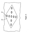
- the Path Finder nodes comprise simple floor tiles (or alternatively sections of skirting board) with a versatile array of LEDs capable of indicating direction in any orientation or of indicating danger or warning by a red "X”.
- Path Finder nodes One important feature of the Path Finder nodes is that the LEDs may be arranged so that they the node can provide a different image depending on the user perspective. This means that an evacuee who is walking towards danger may see a red "X" from any given floor tile whereas an evacuee who is walking away from that danger towards the first evacuee will see a green arrow from the same tile or node.
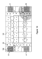
- Figure 10 shows how these three components guide escapees past an unsuitable exit leading ultimately to the suitable exit door, as illustrated in Figure 11 , and then providing warning not to proceed any further down the corridor because it only leads to a cul-de-sac (see Figure 11 )
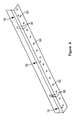
- Stair Finder nodes affixed to the edges of the steps or provided as stair rods, is that they offers not merely navigational assistance, but can also provide important visual cues of the stair edges (or corridor edges) to assist people in the dangerous passage down a stairwell in poor visibility.
- an Exit Finder node 10 can provide warning of a stairway and advice of location.
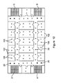
- Figures 12 to 13 comprise highly stylised floor plans illustrating how the system functions as a distributed intelligent system.
- Each node is equipped with identical processing power embedded in an on-board microprocessor and capable of communicating with all other nodes using either wireless or cable protocols.
- Each node has a unique address and is routinely updated with the status of every other node on the network - so that effectively every node has the capability of being a master controller.
- Every other node has capability to deputise if necessary and a hierarchy of succession is embedded in the operating protocol.
- This provides for a disaster-proof protocol in that it is impossible for a disaster to disable the control of the exit navigation.
- the dark shaded dots 100 represent people who need to escape from the rooms 102 of a building. Initially there are no obstacles to any of the four optional stairways A,B,C,D so the navigational nodes of the system, in particular the floor mounted Path Finder nodes 20, each offer guidance simply to the nearest stairwell, as shown in Figure 13 .
- Information about hazards in the environment is provided by a variety of sensor nodes that monitor variables such as traffic, temperature, smoke, connectivity, visibility and other important variables.
- Each node may be provided with a reader for reading a a unique identifier tag associated with a person or object coming into the promximity of the node, whereby the system may provide information regarding the location of such tagged person or object within building or other space within which the nodes are located.
- identifier tag may comprise an RFID tag or similar passive or active transponder device.
- Such identifier tag may also be adapted to provide information on the status or health of a person to which the tag is attached.
- Emergency workers in particular fire fighters, may be provided with a unique identifier tag such that the location of each fire fighter within the building may be determined by the network or nodes and, optionally, the condition of each fire fighter may be determined, allowing injured fire fighters to be pin pointed and rescued from a building and also enabling the system to modify the evacuation strategy for guiding occupants from the building to clear areas where fire fighters require access and/or to guide fire fighters within the building or other enclosed space.
- the network protocol allows the designation of a hand-held or wall mounted human interface unit as the master controller for the network.
- a human interface node gives visibility of all network nodes, providing their status and the status of all environmental variables - and permits human intervention to alter the escape route if necessary.
- Such interface may also provide information regarding the location of persons, in particular tagged persons, within the building or enclosed space within which the system in installed.
Claims (15)
- Un système de guidage d'itinéraire destiné à guider des occupants d'un espace fermé vers un emplacement, tel qu'une sortie, ledit système comprenant un réseau de noeuds interconnectés (20) situés à des emplacements espacés dans l'ensemble dudit espace fermé, au moins certains desdits noeuds (20) étant adaptés de façon à acheminer une instruction de guidage d'itinéraire auxdits occupants, chaque noeud comprenant une unité de commande et un moyen de communication permettant à l'unité de commande de communiquer avec l'unité de commande d'au moins un noeud adjacent de façon à transmettre des informations et/ou des instructions entre des noeuds adjacents (20), où chaque noeud est muni d'un identifiant unique, tel qu'un identifiant numérique ou une adresse, ledit identifiant unique étant communiqué à d'autres noeuds (20) conjointement avec des informations/instructions destinées à permettre l'identification de chaque noeud du système, où l'un des noeuds (20) est désigné en tant que noeud principal, le noeud principal étant adapté de façon à déterminer le fonctionnement de tous les noeuds restants (20), caractérisé en ce que les noeuds (20) sont désignés dans une hiérarchie de succession de sorte que, si le noeud principal existant devient désactivé ou endommagé, un autre noeud conformément à la hiérarchie de succession est désigné comme étant le nouveau noeud principal.
- Un système selon la Revendication 1, où ladite unité de commande de chaque noeud est programmée de façon à commander le fonctionnement du noeud en tant que fonction d'informations et/ou d'instructions reçues d'un ou plusieurs noeuds adjacents (20) et/ou capteurs et à communiquer des informations et/ou instructions à un ou plusieurs autres noeuds (20) en réponse auxdites informations et/ou instructions reçues.
- Un système selon l'une quelconque des Revendications précédentes, où ladite unité de commande comprend une unité de traitement de données numériques ou un microcontrôleur.
- Un système selon l'une quelconque des Revendications précédentes, où ledit moyen de communication comprend un moyen de communication sans fil.
- Un système selon l'une quelconque des Revendications précédentes, où ladite instruction de guidage d'itinéraire peut être fournie aux occupants par un moyen d'affichage audible et/ou visuel et/ou où au moins certains desdits noeuds (20) sont munis d'un moyen d'éclairage (22) pouvant être commandé par le moyen de commande de façon à fournir des informations et/ou un guidage directionnel, ou simplement un éclairage, aux occupants de l'espace fermé et/ou où un ou plusieurs desdits noeuds sont munis d'un moyen d'éclairage (22) destiné à guider les occupants vers une sortie et/ou à avertir les occupants qu'une sortie adjacente n'est pas utilisable.
- Un système selon l'une quelconque des Revendications précédentes, où un ou plusieurs des noeuds (20) comprennent au moins une source lumineuse et un moyen de focalisation conçu de façon à focaliser la lumière en un faisceau (14, 34, 36) projeté à partir du noeud.
- Un système selon la Revendication 6, où un ou plusieurs des noeuds comprennent un moyen de projection d'informations (16, 20), en utilisation, à l'intérieur du(des) faisceau(x) de lumière projetés à partir de celui-ci ou où le moyen de focalisation est conçu de façon à focaliser la lumière provenant de la au moins une source lumineuse en une paire de faisceaux, chaque faisceau étant projeté à partir de sorties dans un corps du noeud ou où ladite au moins une source lumineuse comprend un appareil de projection agencé de façon à projeter des informations (16, 20), en utilisation, sur une surface adjacente au dispositif.
- Un système selon l'une quelconque des Revendications précédentes, où au moins un desdits noeuds est muni d'une interface utilisateur destinée à permettre la commande et/ou la programmation du réseau de guidage d'itinéraire.
- Un système selon l'une quelconque des Revendications précédentes, où au moins un desdits noeuds comprend un écran (42) placé sur un corps du noeud.
- Un système selon la Revendication 9, où ledit écran (42) affiche l'état de certains ou de tous les noeuds (20) du système de façon à surveiller le fonctionnement du système et/ou où ledit écran (42) est combiné avec une interface utilisateur pour la fourniture d'une commande manuelle sur le système.
- Un système selon l'une quelconque des Revendications précédentes, où un ou plusieurs des noeuds (20) sont munis de ou associés à un ou plusieurs capteurs de façon à détecter des conditions environnementales, l'unité de commande desdits un ou plusieurs noeuds (20) fournissant des informations à des noeuds adjacents (20) en fonction d'une entrée provenant desdits un ou plusieurs capteurs.
- Un système selon la Revendication 11, où lesdits un ou plusieurs capteurs comprennent un ou plusieurs capteurs parmi un capteur thermique et/ou un capteur de fumée et/ou un capteur de sons et/ou un capteur de lumière, le capteur de lumière étant conçu de façon à générer un signal en cas de détection d'un niveau de lumière réduit.
- Un système selon l'une quelconque des Revendications précédentes, où un ou plusieurs des noeuds (20) sont munis d'un capteur de proximité, permettant au noeud de déterminer une concentration de foule dans la zone voisine et/ou de déterminer le déplacement de personnes dans la zone du noeud.
- Un système selon la Revendication 13, où ledit capteur de proximité est adapté de façon à détecter et reconnaître une étiquette d'identifiant unique, telle qu'une étiquette RFID, associée à une personne ou un objet adjacent au noeud, de sorte que le noeud puisse identifier la présence de ladite personne ou dudit objet étiqueté adjacent audit noeud.
- Un système selon la Revendication 14, où ladite étiquette d'identifiant unique peut également fournir des informations concernant l'état ou la santé d'une personne à laquelle l'étiquette est fixée, lesdites informations étant reçues par le noeud de façon à permettre de déterminer la condition d'une personne étiquetée par le système.
Applications Claiming Priority (2)
| Application Number | Priority Date | Filing Date | Title |
|---|---|---|---|
| GBGB0820606.2A GB0820606D0 (en) | 2008-11-11 | 2008-11-11 | Route guidance and evacuation system |
| PCT/EP2009/008013 WO2010054794A2 (fr) | 2008-11-11 | 2009-11-10 | Système de guidage d’itinéraire |
Publications (2)
| Publication Number | Publication Date |
|---|---|
| EP2366176A2 EP2366176A2 (fr) | 2011-09-21 |
| EP2366176B1 true EP2366176B1 (fr) | 2013-06-05 |
Family
ID=40139721
Family Applications (1)
| Application Number | Title | Priority Date | Filing Date |
|---|---|---|---|
| EP09795690.8A Not-in-force EP2366176B1 (fr) | 2008-11-11 | 2009-11-10 | Système de guidage d itinéraire |
Country Status (5)
| Country | Link |
|---|---|
| US (1) | US20110267179A1 (fr) |
| EP (1) | EP2366176B1 (fr) |
| CA (1) | CA2743233A1 (fr) |
| GB (1) | GB0820606D0 (fr) |
| WO (1) | WO2010054794A2 (fr) |
Cited By (2)
| Publication number | Priority date | Publication date | Assignee | Title |
|---|---|---|---|---|
| CN108922086A (zh) * | 2018-06-29 | 2018-11-30 | 贵州省仁怀市西科电脑科技有限公司 | 安防报警与引导方法 |
| CN108961628A (zh) * | 2018-06-29 | 2018-12-07 | 贵州省仁怀市西科电脑科技有限公司 | 安防报警与引导系统 |
Families Citing this family (34)
| Publication number | Priority date | Publication date | Assignee | Title |
|---|---|---|---|---|
| TWI407285B (zh) * | 2010-06-15 | 2013-09-01 | Hong Hsi Ko | 基於路徑導向的發光地磚指引系統及其方法 |
| US20130282280A1 (en) * | 2010-06-29 | 2013-10-24 | Lightstep Technologies Limited | Control module for a route guidance system |
| US9230419B2 (en) | 2010-07-27 | 2016-01-05 | Rite-Hite Holding Corporation | Methods and apparatus to detect and warn proximate entities of interest |
| CN106251525A (zh) * | 2010-11-19 | 2016-12-21 | 株式会社尼康 | 系统以及电子设备 |
| EP2643825B1 (fr) | 2010-11-22 | 2016-01-27 | Lumenox Limited | Affichage d'aide en cas d'urgence |
| US20130116922A1 (en) * | 2011-11-08 | 2013-05-09 | Hon Hai Precision Industry Co., Ltd. | Emergency guiding system, server and portable device using augmented reality |
| EP2597423A1 (fr) * | 2011-11-22 | 2013-05-29 | Astrium GmbH | Système de navigation et de location intérieur et procédé de location d'une unité mobile |
| KR101950998B1 (ko) * | 2012-01-03 | 2019-02-21 | 삼성전자주식회사 | 엔에프씨 태그를 이용한 서비스 제공 시스템 및 방법 |
| US9261368B2 (en) * | 2012-06-20 | 2016-02-16 | Here Global B.V. | Method and apparatus for using a device flashlight as feedback for guidance purposes |
| WO2014121329A1 (fr) * | 2013-02-06 | 2014-08-14 | University Of Technology, Sydney | Système mis en œuvre par ordinateur pour influencer une foule |
| WO2014153027A1 (fr) * | 2013-03-19 | 2014-09-25 | Michael Simmons | Indicateur de guidage et système d'aide à la sortie |
| US9959717B2 (en) * | 2013-05-17 | 2018-05-01 | Networked Emergency Systems Inc. | Security and first-responder emergency lighting system |
| AU2014339811B2 (en) | 2013-10-25 | 2019-05-09 | Jean Bennett | Apparatus and methods for testing visual function and functional vision at varying luminance levels |
| JP5781144B2 (ja) * | 2013-12-11 | 2015-09-16 | 株式会社ティーエヌケー | 誘導システム |
| JP6708122B2 (ja) * | 2014-06-30 | 2020-06-10 | 日本電気株式会社 | 誘導処理装置及び誘導方法 |
| CN105233436A (zh) * | 2015-09-01 | 2016-01-13 | 中国十七冶集团有限公司 | 一种安全疏散装置及使用方法 |
| KR20170130234A (ko) | 2016-05-18 | 2017-11-28 | 삼성전자주식회사 | 실내 네비게이션을 제공하는 전자장치 및 이의 방법 |
| US10802665B2 (en) | 2016-10-05 | 2020-10-13 | Motorola Solutions, Inc. | System and method for projecting graphical objects |
| US10600112B2 (en) | 2016-10-11 | 2020-03-24 | Walmart Apollo, Llc | Systems and methods for directing a user to a location of interest |
| US10026278B1 (en) | 2017-01-17 | 2018-07-17 | International Business Machines Corporation | Optimal evacuation plans in emergency situations |
| WO2018170226A1 (fr) | 2017-03-15 | 2018-09-20 | Carrier Corporation | Système et procédé de détection d'incendie et de vérification de panneaux de guidage vers le chemin de retraite en conséquence |
| JP7142819B2 (ja) * | 2017-08-21 | 2022-09-28 | ホーチキ株式会社 | カードリーダー |
| CN108091089B (zh) * | 2017-12-27 | 2021-05-25 | 余姚市立鑫电子有限公司 | 应急照明和疏散指示检测系统及方法 |
| US10679480B2 (en) * | 2018-03-22 | 2020-06-09 | Paul L. Eckert | Event indicator system |
| JP6917969B2 (ja) * | 2018-11-09 | 2021-08-11 | 能美防災株式会社 | 防災システム |
| US10553085B1 (en) | 2019-01-25 | 2020-02-04 | Lghorizon, Llc | Home emergency guidance and advisement system |
| DE202019001159U1 (de) * | 2019-03-12 | 2019-04-04 | Blue Star Gmbh | Treppensystemvorrichtung |
| US11514764B2 (en) * | 2019-11-21 | 2022-11-29 | Alarm.Com Incorporated | Smartlock system for improved fire safety |
| CN111341047B (zh) * | 2020-02-14 | 2022-04-15 | Oppo(重庆)智能科技有限公司 | 意外事件处理方法及相关设备 |
| US11915571B2 (en) * | 2020-06-02 | 2024-02-27 | Joshua UPDIKE | Systems and methods for dynamically monitoring distancing using a spatial monitoring platform |
| US11043095B1 (en) | 2020-06-16 | 2021-06-22 | Lghorizon, Llc | Predictive building emergency guidance and advisement system |
| US10991216B1 (en) * | 2020-12-04 | 2021-04-27 | Khaled Alali | Auditory and visual guidance system for emergency evacuation |
| US11583770B2 (en) | 2021-03-01 | 2023-02-21 | Lghorizon, Llc | Systems and methods for machine learning-based emergency egress and advisement |
| US11626002B2 (en) | 2021-07-15 | 2023-04-11 | Lghorizon, Llc | Building security and emergency detection and advisement system |
Family Cites Families (11)
| Publication number | Priority date | Publication date | Assignee | Title |
|---|---|---|---|---|
| US4737764A (en) * | 1986-05-30 | 1988-04-12 | Collins & Aikman Corporation | Modular floor covering units with built-in lighting |
| US6237266B1 (en) * | 1997-07-11 | 2001-05-29 | Daniel J. Tassey | Evacuation route having photoluminescent indicators |
| US6150943A (en) * | 1999-07-14 | 2000-11-21 | American Xtal Technology, Inc. | Laser director for fire evacuation path |
| WO2001004853A1 (fr) * | 1999-07-14 | 2001-01-18 | Lyte Optronics, Inc | Systeme laser de flechage du trajet de sortie en cas d'incendie |
| GB2370675B (en) * | 2000-11-15 | 2003-04-30 | Maurice Bligh | Colour-coded evacuation signalling system |
| DE10246033B4 (de) * | 2002-10-02 | 2006-02-23 | Novar Gmbh | Fluchtleitsystem |
| US20050212677A1 (en) * | 2004-02-13 | 2005-09-29 | Byrne James T | Method and apparatus for providing information regarding an emergency |
| JP4009606B2 (ja) * | 2004-03-22 | 2007-11-21 | 明司 的場 | 救助システム |
| CA2569800A1 (fr) * | 2004-06-08 | 2005-12-22 | Kieran Patterson | Eclairage de securite |
| US20070194922A1 (en) * | 2006-02-17 | 2007-08-23 | Lear Corporation | Safe warn building system and method |
| NO327587B1 (no) | 2007-11-02 | 2009-08-31 | Magne Ege Dahl | Anordning og system for identifisering, adgang, lokalisering og orientering i bygninger, skip og andre konstruksjoner |
-
2008
- 2008-11-11 GB GBGB0820606.2A patent/GB0820606D0/en not_active Ceased
-
2009
- 2009-11-10 EP EP09795690.8A patent/EP2366176B1/fr not_active Not-in-force
- 2009-11-10 CA CA2743233A patent/CA2743233A1/fr not_active Abandoned
- 2009-11-10 WO PCT/EP2009/008013 patent/WO2010054794A2/fr active Application Filing
- 2009-11-10 US US13/128,450 patent/US20110267179A1/en not_active Abandoned
Cited By (4)
| Publication number | Priority date | Publication date | Assignee | Title |
|---|---|---|---|---|
| CN108922086A (zh) * | 2018-06-29 | 2018-11-30 | 贵州省仁怀市西科电脑科技有限公司 | 安防报警与引导方法 |
| CN108961628A (zh) * | 2018-06-29 | 2018-12-07 | 贵州省仁怀市西科电脑科技有限公司 | 安防报警与引导系统 |
| CN108961628B (zh) * | 2018-06-29 | 2020-01-17 | 贵州省仁怀市西科电脑科技有限公司 | 安防报警与引导系统 |
| CN108922086B (zh) * | 2018-06-29 | 2020-01-17 | 贵州省仁怀市西科电脑科技有限公司 | 安防报警与引导方法 |
Also Published As
| Publication number | Publication date |
|---|---|
| WO2010054794A3 (fr) | 2010-08-05 |
| US20110267179A1 (en) | 2011-11-03 |
| WO2010054794A2 (fr) | 2010-05-20 |
| CA2743233A1 (fr) | 2010-05-20 |
| GB0820606D0 (en) | 2008-12-17 |
| EP2366176A2 (fr) | 2011-09-21 |
Similar Documents
| Publication | Publication Date | Title |
|---|---|---|
| EP2366176B1 (fr) | Système de guidage d itinéraire | |
| US7619538B1 (en) | Programmable, directing evacuation systems: apparatus and method | |
| US7026947B2 (en) | Building emergency path finding systems and method | |
| US6646545B2 (en) | Color-coded evacuation signaling system | |
| US8970354B2 (en) | Electronic guides, incident response methods, incident response systems, and incident monitoring methods | |
| RU2544737C2 (ru) | Устройство для эвакуации и указатель пути эвакуации для него | |
| US7940010B2 (en) | Emergency lighting | |
| KR101771579B1 (ko) | 통합형 센서모듈을 이용한 상시 환경제어 및 재난대응 관제시스템 | |
| ES2198939T3 (es) | Detector de incendios y sistema de alarma de incendios. | |
| US20070152808A1 (en) | Intelligent directional fire alarm system | |
| CN106355827B (zh) | 具有外显式即时救灾警示系统的装置及其使用方法 | |
| KR100729632B1 (ko) | 열연기 탈출체험시스템 | |
| KR101018583B1 (ko) | 지능형 소방 방재 시스템 | |
| CN110081399B (zh) | 一种智慧路灯系统及智慧路灯 | |
| US9685051B2 (en) | Evacuation assistance apparatus | |
| Bukowski et al. | Egress concepts and design approaches | |
| KR20190128321A (ko) | 레이저를 이용한 대피 기능을 갖는 스마트 비상등 시스템 | |
| WO2009017628A2 (fr) | Système, appareil et procédé de guidage progressif, programmable | |
| KR100945857B1 (ko) | 멀티 소방 피난 유도장치 | |
| EP0361973A2 (fr) | Voie illuminée de sortie de secours en cas d'incendie | |
| RU2760114C1 (ru) | Система эвакуации и навигации в зданиях | |
| KR20210006277A (ko) | 화재 조기 감지 및 안전 대피 유도 시스템과 그 방법 | |
| Wong et al. | A Review of Dynamic Directional Exit Signage: Challenges & Perspectives | |
| KR20230123335A (ko) | 지능형 피난안내도 | |
| Lyons | Emergency Lighting: For Industrial, Commercial and Residential Premises |
Legal Events
| Date | Code | Title | Description |
|---|---|---|---|
| TPAC | Observations filed by third parties |
Free format text: ORIGINAL CODE: EPIDOSNTIPA |
|
| PUAI | Public reference made under article 153(3) epc to a published international application that has entered the european phase |
Free format text: ORIGINAL CODE: 0009012 |
|
| 17P | Request for examination filed |
Effective date: 20110614 |
|
| AK | Designated contracting states |
Kind code of ref document: A2 Designated state(s): AT BE BG CH CY CZ DE DK EE ES FI FR GB GR HR HU IE IS IT LI LT LU LV MC MK MT NL NO PL PT RO SE SI SK SM TR |
|
| DAX | Request for extension of the european patent (deleted) | ||
| GRAP | Despatch of communication of intention to grant a patent |
Free format text: ORIGINAL CODE: EPIDOSNIGR1 |
|
| GRAS | Grant fee paid |
Free format text: ORIGINAL CODE: EPIDOSNIGR3 |
|
| GRAA | (expected) grant |
Free format text: ORIGINAL CODE: 0009210 |
|
| AK | Designated contracting states |
Kind code of ref document: B1 Designated state(s): AT BE BG CH CY CZ DE DK EE ES FI FR GB GR HR HU IE IS IT LI LT LU LV MC MK MT NL NO PL PT RO SE SI SK SM TR |
|
| REG | Reference to a national code |
Ref country code: GB Ref legal event code: FG4D |
|
| REG | Reference to a national code |
Ref country code: CH Ref legal event code: EP |
|
| REG | Reference to a national code |
Ref country code: AT Ref legal event code: REF Ref document number: 616049 Country of ref document: AT Kind code of ref document: T Effective date: 20130615 |
|
| REG | Reference to a national code |
Ref country code: IE Ref legal event code: FG4D |
|
| REG | Reference to a national code |
Ref country code: DE Ref legal event code: R096 Ref document number: 602009016298 Country of ref document: DE Effective date: 20130801 |
|
| REG | Reference to a national code |
Ref country code: AT Ref legal event code: MK05 Ref document number: 616049 Country of ref document: AT Kind code of ref document: T Effective date: 20130605 |
|
| PG25 | Lapsed in a contracting state [announced via postgrant information from national office to epo] |
Ref country code: AT Free format text: LAPSE BECAUSE OF FAILURE TO SUBMIT A TRANSLATION OF THE DESCRIPTION OR TO PAY THE FEE WITHIN THE PRESCRIBED TIME-LIMIT Effective date: 20130605 Ref country code: ES Free format text: LAPSE BECAUSE OF FAILURE TO SUBMIT A TRANSLATION OF THE DESCRIPTION OR TO PAY THE FEE WITHIN THE PRESCRIBED TIME-LIMIT Effective date: 20130916 Ref country code: SE Free format text: LAPSE BECAUSE OF FAILURE TO SUBMIT A TRANSLATION OF THE DESCRIPTION OR TO PAY THE FEE WITHIN THE PRESCRIBED TIME-LIMIT Effective date: 20130605 Ref country code: NO Free format text: LAPSE BECAUSE OF FAILURE TO SUBMIT A TRANSLATION OF THE DESCRIPTION OR TO PAY THE FEE WITHIN THE PRESCRIBED TIME-LIMIT Effective date: 20130905 Ref country code: SI Free format text: LAPSE BECAUSE OF FAILURE TO SUBMIT A TRANSLATION OF THE DESCRIPTION OR TO PAY THE FEE WITHIN THE PRESCRIBED TIME-LIMIT Effective date: 20130605 Ref country code: GR Free format text: LAPSE BECAUSE OF FAILURE TO SUBMIT A TRANSLATION OF THE DESCRIPTION OR TO PAY THE FEE WITHIN THE PRESCRIBED TIME-LIMIT Effective date: 20130906 Ref country code: LT Free format text: LAPSE BECAUSE OF FAILURE TO SUBMIT A TRANSLATION OF THE DESCRIPTION OR TO PAY THE FEE WITHIN THE PRESCRIBED TIME-LIMIT Effective date: 20130605 |
|
| REG | Reference to a national code |
Ref country code: NL Ref legal event code: VDEP Effective date: 20130605 |
|
| REG | Reference to a national code |
Ref country code: LT Ref legal event code: MG4D |
|
| PG25 | Lapsed in a contracting state [announced via postgrant information from national office to epo] |
Ref country code: BG Free format text: LAPSE BECAUSE OF FAILURE TO SUBMIT A TRANSLATION OF THE DESCRIPTION OR TO PAY THE FEE WITHIN THE PRESCRIBED TIME-LIMIT Effective date: 20130905 Ref country code: PL Free format text: LAPSE BECAUSE OF FAILURE TO SUBMIT A TRANSLATION OF THE DESCRIPTION OR TO PAY THE FEE WITHIN THE PRESCRIBED TIME-LIMIT Effective date: 20130605 Ref country code: HR Free format text: LAPSE BECAUSE OF FAILURE TO SUBMIT A TRANSLATION OF THE DESCRIPTION OR TO PAY THE FEE WITHIN THE PRESCRIBED TIME-LIMIT Effective date: 20130605 |
|
| PG25 | Lapsed in a contracting state [announced via postgrant information from national office to epo] |
Ref country code: LV Free format text: LAPSE BECAUSE OF FAILURE TO SUBMIT A TRANSLATION OF THE DESCRIPTION OR TO PAY THE FEE WITHIN THE PRESCRIBED TIME-LIMIT Effective date: 20130605 |
|
| PG25 | Lapsed in a contracting state [announced via postgrant information from national office to epo] |
Ref country code: IS Free format text: LAPSE BECAUSE OF FAILURE TO SUBMIT A TRANSLATION OF THE DESCRIPTION OR TO PAY THE FEE WITHIN THE PRESCRIBED TIME-LIMIT Effective date: 20131005 Ref country code: BE Free format text: LAPSE BECAUSE OF FAILURE TO SUBMIT A TRANSLATION OF THE DESCRIPTION OR TO PAY THE FEE WITHIN THE PRESCRIBED TIME-LIMIT Effective date: 20130605 Ref country code: EE Free format text: LAPSE BECAUSE OF FAILURE TO SUBMIT A TRANSLATION OF THE DESCRIPTION OR TO PAY THE FEE WITHIN THE PRESCRIBED TIME-LIMIT Effective date: 20130605 Ref country code: PT Free format text: LAPSE BECAUSE OF FAILURE TO SUBMIT A TRANSLATION OF THE DESCRIPTION OR TO PAY THE FEE WITHIN THE PRESCRIBED TIME-LIMIT Effective date: 20131007 Ref country code: CZ Free format text: LAPSE BECAUSE OF FAILURE TO SUBMIT A TRANSLATION OF THE DESCRIPTION OR TO PAY THE FEE WITHIN THE PRESCRIBED TIME-LIMIT Effective date: 20130605 Ref country code: SK Free format text: LAPSE BECAUSE OF FAILURE TO SUBMIT A TRANSLATION OF THE DESCRIPTION OR TO PAY THE FEE WITHIN THE PRESCRIBED TIME-LIMIT Effective date: 20130605 |
|
| PG25 | Lapsed in a contracting state [announced via postgrant information from national office to epo] |
Ref country code: NL Free format text: LAPSE BECAUSE OF FAILURE TO SUBMIT A TRANSLATION OF THE DESCRIPTION OR TO PAY THE FEE WITHIN THE PRESCRIBED TIME-LIMIT Effective date: 20130605 Ref country code: RO Free format text: LAPSE BECAUSE OF FAILURE TO SUBMIT A TRANSLATION OF THE DESCRIPTION OR TO PAY THE FEE WITHIN THE PRESCRIBED TIME-LIMIT Effective date: 20130605 |
|
| PLBE | No opposition filed within time limit |
Free format text: ORIGINAL CODE: 0009261 |
|
| STAA | Information on the status of an ep patent application or granted ep patent |
Free format text: STATUS: NO OPPOSITION FILED WITHIN TIME LIMIT |
|
| PG25 | Lapsed in a contracting state [announced via postgrant information from national office to epo] |
Ref country code: DK Free format text: LAPSE BECAUSE OF FAILURE TO SUBMIT A TRANSLATION OF THE DESCRIPTION OR TO PAY THE FEE WITHIN THE PRESCRIBED TIME-LIMIT Effective date: 20130605 |
|
| 26N | No opposition filed |
Effective date: 20140306 |
|
| PG25 | Lapsed in a contracting state [announced via postgrant information from national office to epo] |
Ref country code: IT Free format text: LAPSE BECAUSE OF FAILURE TO SUBMIT A TRANSLATION OF THE DESCRIPTION OR TO PAY THE FEE WITHIN THE PRESCRIBED TIME-LIMIT Effective date: 20130605 |
|
| REG | Reference to a national code |
Ref country code: DE Ref legal event code: R097 Ref document number: 602009016298 Country of ref document: DE Effective date: 20140306 |
|
| REG | Reference to a national code |
Ref country code: CH Ref legal event code: PL |
|
| PG25 | Lapsed in a contracting state [announced via postgrant information from national office to epo] |
Ref country code: CH Free format text: LAPSE BECAUSE OF NON-PAYMENT OF DUE FEES Effective date: 20131130 Ref country code: MC Free format text: LAPSE BECAUSE OF FAILURE TO SUBMIT A TRANSLATION OF THE DESCRIPTION OR TO PAY THE FEE WITHIN THE PRESCRIBED TIME-LIMIT Effective date: 20130605 Ref country code: LI Free format text: LAPSE BECAUSE OF NON-PAYMENT OF DUE FEES Effective date: 20131130 |
|
| REG | Reference to a national code |
Ref country code: IE Ref legal event code: MM4A |
|
| PG25 | Lapsed in a contracting state [announced via postgrant information from national office to epo] |
Ref country code: IE Free format text: LAPSE BECAUSE OF NON-PAYMENT OF DUE FEES Effective date: 20131110 |
|
| REG | Reference to a national code |
Ref country code: DE Ref legal event code: R082 Ref document number: 602009016298 Country of ref document: DE Representative=s name: PATENTANWAELTE WALLACH, KOCH & PARTNER, DE |
|
| REG | Reference to a national code |
Ref country code: DE Ref legal event code: R082 Ref document number: 602009016298 Country of ref document: DE Representative=s name: PATENTANWAELTE WALLACH, KOCH & PARTNER, DE Effective date: 20150417 Ref country code: DE Ref legal event code: R081 Ref document number: 602009016298 Country of ref document: DE Owner name: BARRON MCCANN HOLDINGS 2 LIMITED, GB Free format text: FORMER OWNER: PATTERSON, KIERAN, LURGAN, GB Effective date: 20150417 Ref country code: DE Ref legal event code: R081 Ref document number: 602009016298 Country of ref document: DE Owner name: LIGHTSTEP INNOVATIONS LIMITED, GB Free format text: FORMER OWNER: PATTERSON, KIERAN, LURGAN, GB Effective date: 20150417 Ref country code: DE Ref legal event code: R082 Ref document number: 602009016298 Country of ref document: DE Representative=s name: PATENTANWAELTE WALLACH, KOCH, DR. HAIBACH, FEL, DE Effective date: 20150417 |
|
| PG25 | Lapsed in a contracting state [announced via postgrant information from national office to epo] |
Ref country code: SM Free format text: LAPSE BECAUSE OF FAILURE TO SUBMIT A TRANSLATION OF THE DESCRIPTION OR TO PAY THE FEE WITHIN THE PRESCRIBED TIME-LIMIT Effective date: 20130605 |
|
| PG25 | Lapsed in a contracting state [announced via postgrant information from national office to epo] |
Ref country code: CY Free format text: LAPSE BECAUSE OF FAILURE TO SUBMIT A TRANSLATION OF THE DESCRIPTION OR TO PAY THE FEE WITHIN THE PRESCRIBED TIME-LIMIT Effective date: 20130605 |
|
| PG25 | Lapsed in a contracting state [announced via postgrant information from national office to epo] |
Ref country code: LU Free format text: LAPSE BECAUSE OF NON-PAYMENT OF DUE FEES Effective date: 20131110 Ref country code: HU Free format text: LAPSE BECAUSE OF FAILURE TO SUBMIT A TRANSLATION OF THE DESCRIPTION OR TO PAY THE FEE WITHIN THE PRESCRIBED TIME-LIMIT; INVALID AB INITIO Effective date: 20091110 Ref country code: MK Free format text: LAPSE BECAUSE OF FAILURE TO SUBMIT A TRANSLATION OF THE DESCRIPTION OR TO PAY THE FEE WITHIN THE PRESCRIBED TIME-LIMIT Effective date: 20130605 |
|
| PG25 | Lapsed in a contracting state [announced via postgrant information from national office to epo] |
Ref country code: MT Free format text: LAPSE BECAUSE OF FAILURE TO SUBMIT A TRANSLATION OF THE DESCRIPTION OR TO PAY THE FEE WITHIN THE PRESCRIBED TIME-LIMIT Effective date: 20130605 |
|
| REG | Reference to a national code |
Ref country code: FR Ref legal event code: PLFP Year of fee payment: 7 |
|
| PGFP | Annual fee paid to national office [announced via postgrant information from national office to epo] |
Ref country code: DE Payment date: 20151119 Year of fee payment: 7 Ref country code: FI Payment date: 20151111 Year of fee payment: 7 Ref country code: GB Payment date: 20151104 Year of fee payment: 7 Ref country code: TR Payment date: 20151105 Year of fee payment: 7 |
|
| PGFP | Annual fee paid to national office [announced via postgrant information from national office to epo] |
Ref country code: FR Payment date: 20151119 Year of fee payment: 7 |
|
| REG | Reference to a national code |
Ref country code: DE Ref legal event code: R119 Ref document number: 602009016298 Country of ref document: DE |
|
| GBPC | Gb: european patent ceased through non-payment of renewal fee |
Effective date: 20161110 |
|
| PG25 | Lapsed in a contracting state [announced via postgrant information from national office to epo] |
Ref country code: FI Free format text: LAPSE BECAUSE OF NON-PAYMENT OF DUE FEES Effective date: 20161110 |
|
| REG | Reference to a national code |
Ref country code: FR Ref legal event code: ST Effective date: 20170731 |
|
| PG25 | Lapsed in a contracting state [announced via postgrant information from national office to epo] |
Ref country code: FR Free format text: LAPSE BECAUSE OF NON-PAYMENT OF DUE FEES Effective date: 20161130 |
|
| PG25 | Lapsed in a contracting state [announced via postgrant information from national office to epo] |
Ref country code: DE Free format text: LAPSE BECAUSE OF NON-PAYMENT OF DUE FEES Effective date: 20170601 Ref country code: GB Free format text: LAPSE BECAUSE OF NON-PAYMENT OF DUE FEES Effective date: 20161110 |
|
| PG25 | Lapsed in a contracting state [announced via postgrant information from national office to epo] |
Ref country code: TR Free format text: LAPSE BECAUSE OF NON-PAYMENT OF DUE FEES Effective date: 20161110 |