EP2366121B1 - System und verfahren zur ballbesitzerkennung mit hilfe passiver felderzeugung - Google Patents
System und verfahren zur ballbesitzerkennung mit hilfe passiver felderzeugung Download PDFInfo
- Publication number
- EP2366121B1 EP2366121B1 EP09806079A EP09806079A EP2366121B1 EP 2366121 B1 EP2366121 B1 EP 2366121B1 EP 09806079 A EP09806079 A EP 09806079A EP 09806079 A EP09806079 A EP 09806079A EP 2366121 B1 EP2366121 B1 EP 2366121B1
- Authority
- EP
- European Patent Office
- Prior art keywords
- magnetic field
- ball
- detecting
- permanent magnet
- detection
- Prior art date
- Legal status (The legal status is an assumption and is not a legal conclusion. Google has not performed a legal analysis and makes no representation as to the accuracy of the status listed.)
- Not-in-force
Links
Images


Classifications
-
- G—PHYSICS
- G01—MEASURING; TESTING
- G01V—GEOPHYSICS; GRAVITATIONAL MEASUREMENTS; DETECTING MASSES OR OBJECTS; TAGS
- G01V3/00—Electric or magnetic prospecting or detecting; Measuring magnetic field characteristics of the earth, e.g. declination, deviation
- G01V3/08—Electric or magnetic prospecting or detecting; Measuring magnetic field characteristics of the earth, e.g. declination, deviation operating with magnetic or electric fields produced or modified by objects or geological structures or by detecting devices
- G01V3/081—Electric or magnetic prospecting or detecting; Measuring magnetic field characteristics of the earth, e.g. declination, deviation operating with magnetic or electric fields produced or modified by objects or geological structures or by detecting devices the magnetic field is produced by the objects or geological structures
-
- A—HUMAN NECESSITIES
- A63—SPORTS; GAMES; AMUSEMENTS
- A63B—APPARATUS FOR PHYSICAL TRAINING, GYMNASTICS, SWIMMING, CLIMBING, OR FENCING; BALL GAMES; TRAINING EQUIPMENT
- A63B24/00—Electric or electronic controls for exercising apparatus of preceding groups; Controlling or monitoring of exercises, sportive games, training or athletic performances
- A63B24/0021—Tracking a path or terminating locations
-
- A—HUMAN NECESSITIES
- A63—SPORTS; GAMES; AMUSEMENTS
- A63B—APPARATUS FOR PHYSICAL TRAINING, GYMNASTICS, SWIMMING, CLIMBING, OR FENCING; BALL GAMES; TRAINING EQUIPMENT
- A63B43/00—Balls with special arrangements
-
- A—HUMAN NECESSITIES
- A63—SPORTS; GAMES; AMUSEMENTS
- A63B—APPARATUS FOR PHYSICAL TRAINING, GYMNASTICS, SWIMMING, CLIMBING, OR FENCING; BALL GAMES; TRAINING EQUIPMENT
- A63B24/00—Electric or electronic controls for exercising apparatus of preceding groups; Controlling or monitoring of exercises, sportive games, training or athletic performances
- A63B24/0021—Tracking a path or terminating locations
- A63B2024/0028—Tracking the path of an object, e.g. a ball inside a soccer pitch
-
- A—HUMAN NECESSITIES
- A63—SPORTS; GAMES; AMUSEMENTS
- A63B—APPARATUS FOR PHYSICAL TRAINING, GYMNASTICS, SWIMMING, CLIMBING, OR FENCING; BALL GAMES; TRAINING EQUIPMENT
- A63B24/00—Electric or electronic controls for exercising apparatus of preceding groups; Controlling or monitoring of exercises, sportive games, training or athletic performances
- A63B24/0021—Tracking a path or terminating locations
- A63B2024/0056—Tracking a path or terminating locations for statistical or strategic analysis
-
- A—HUMAN NECESSITIES
- A63—SPORTS; GAMES; AMUSEMENTS
- A63B—APPARATUS FOR PHYSICAL TRAINING, GYMNASTICS, SWIMMING, CLIMBING, OR FENCING; BALL GAMES; TRAINING EQUIPMENT
- A63B2209/00—Characteristics of used materials
- A63B2209/08—Characteristics of used materials magnetic
-
- A—HUMAN NECESSITIES
- A63—SPORTS; GAMES; AMUSEMENTS
- A63B—APPARATUS FOR PHYSICAL TRAINING, GYMNASTICS, SWIMMING, CLIMBING, OR FENCING; BALL GAMES; TRAINING EQUIPMENT
- A63B2220/00—Measuring of physical parameters relating to sporting activity
- A63B2220/10—Positions
- A63B2220/13—Relative positions
-
- A—HUMAN NECESSITIES
- A63—SPORTS; GAMES; AMUSEMENTS
- A63B—APPARATUS FOR PHYSICAL TRAINING, GYMNASTICS, SWIMMING, CLIMBING, OR FENCING; BALL GAMES; TRAINING EQUIPMENT
- A63B2220/00—Measuring of physical parameters relating to sporting activity
- A63B2220/80—Special sensors, transducers or devices therefor
- A63B2220/83—Special sensors, transducers or devices therefor characterised by the position of the sensor
- A63B2220/836—Sensors arranged on the body of the user
-
- A—HUMAN NECESSITIES
- A63—SPORTS; GAMES; AMUSEMENTS
- A63B—APPARATUS FOR PHYSICAL TRAINING, GYMNASTICS, SWIMMING, CLIMBING, OR FENCING; BALL GAMES; TRAINING EQUIPMENT
- A63B2225/00—Miscellaneous features of sport apparatus, devices or equipment
- A63B2225/50—Wireless data transmission, e.g. by radio transmitters or telemetry
-
- A—HUMAN NECESSITIES
- A63—SPORTS; GAMES; AMUSEMENTS
- A63B—APPARATUS FOR PHYSICAL TRAINING, GYMNASTICS, SWIMMING, CLIMBING, OR FENCING; BALL GAMES; TRAINING EQUIPMENT
- A63B2243/00—Specific ball sports not provided for in A63B2102/00 - A63B2102/38
- A63B2243/0025—Football
Definitions
- the present invention generally relates to detecting and providing player-related information in ball sports, and more particularly to detecting and providing information regarding a player's possession of the ball.
- the WO 01/37945 A2 describes the tracking of gaming devices with detectable signatures. Further prior art are from the DE 20 2004 006680 U1 , from the WO 2008/043450 A1 and from the US 2006/178235 A1 known.
- the present invention remedy.
- the present invention is based on the recognition that it is possible and advantageous to generate a magnetic field in the game device, for example the ball, by one or more permanent magnets.
- the player himself must thereby carry only a small device, preferably housed in the shoe or shin guards of the player wear.
- This device includes a magnetic field sensor for detecting the magnetic field of the one or more permanent magnets.
- the signals of the magnetic field sensor are evaluated by a control unit to detect whether the device, and thus the foot of the player, in close proximity to the ball located. If the control unit detects such a ball possession event, this information is output together with a time stamp.
- the information can also The storage process is either continuously repeated as long as the magnetic field of the permanent magnet is detected, or the event is stored with a start and an end timestamp.
- control unit can transmit the detection of the magnetic field of the permanent magnet via a corresponding radio module to a central detection unit.
- a timely evaluation of possession of all players is possible. This benefits the viewers, who can access such information and statistics during the match, while saving is possible only during break times or after the end of the game.
- FIG. 1 shows a schematic representation of a system and a device for detecting a magnetic field and a game ball according to an embodiment of the present invention.
- the system includes the game ball 100, which is equipped with at least one permanent magnet.
- FIG. 1 shows a first permanent magnet 110A, which is preferably mounted in the middle of the ball. This can be done via a clamping with threads or springs. In another embodiment, the permanent magnet 110A is held in its central position by a soft foam that fills the interior of the ball.
- two or more permanent magnets are integrated or mounted in the ball wall. This can be accomplished, for example, during the manufacture of an inner shell or inner shell of the playing ball.
- the present invention is not limited to these mounting methods nor to the described and shown number of permanent magnets.
- the permanent magnets in the game ball are used to generate a magnetic field with a preferably predetermined range.
- the selected range can be determined, for example, by the size or the material of the permanent magnet.
- both the determination of direct possession of the ball, d. H. allow a contact between the football shoe and ball, as well as a determination by several football boots in the vicinity of the game ball, so as to allow conclusions about the so-called ball possession of individual players.
- the range of the permanent magnets allows devices of several players, for example trying to gain possession of the ball, to detect the distance to the ball.
- permanent magnets are particularly cost-effective for the entire system.
- a ball does not require its own power supply, as is the case with magnetic field generators.
- a permanent magnet is cheaper and easier to mount in the ball as solutions that include electronic circuits.
- the FIG. 1 further shows a device 130 for detecting possession of the ball or proximity to a ball.
- the device 130 is shown in FIG FIG. 1 shown to be in the immediate region of influence of the magnetic field 120 of one of the permanent magnets.
- the device 130 may determine possession of the ball.
- the device 130 compare the measured magnetic field strength with a threshold and recognize when exceeding the threshold, a permanent magnet or possession of the ball.
- this threshold value can be set such that a range of up to 25 cm around the ball is interpreted as possession of the ball.
- the FIG. 2 shows the above-mentioned device 130 in more detail. It contains the magnetic field sensor 210, which generates a sensor signal as a function of the measured magnetic field strength.
- the device 130 may also be equipped with two or more magnetic field sensors.
- the magnetic field sensor 122 preferably includes a magnetoresistive element or a Hall element. If the magnetic field strength is measured with magnetoresistive sensors as magnetic field-dependent resistors, these can be switched to a bridge. The output signal of the bridge can be amplified by a differential amplifier. The output voltage is a direct measure of the field strength of the measured magnetic field. In order to obtain an evaluable signal at every possible axis of rotation of the game ball, two or three sensors offset by 90 degrees each can be used.
- the field strength can be measured with Hall sensors.
- Hall sensors generate a voltage proportional to the field strength.
- This voltage can be amplified by means of a differential amplifier.
- the output voltage is a direct measure of the field strength of the magnetic field.
- the evaluation of this voltage can be done either discretely via an analog circuit or with the aid of a control unit 220, for example a microcontroller.
- two or three sensors offset by 90 degrees can be used.
- the control unit 220 which is coupled to the magnetic field sensor for detecting an output signal, further processes the signal.
- the controller 220 compares the received signal of the magnetic field sensor 210 with a threshold to determine if a permanent magnet is in close proximity to the magnetic field sensor 210.
- the device 130 may also include a memory unit 225 in one embodiment of the present invention.
- This memory 225 allows the control unit 220 to store events, such as exceeding a threshold by the magnetic field sensor signal.
- the FIG. 2 also shows an output module 230, which allows the output of the detected events.
- the output unit 230 is provided by a transmitting unit.
- the transmission unit is designed so that it can transmit data to a central detection unit.
- This central detection unit may, for example, be located at the edge of the field or at another location from which signals from transmitting units can be received from the entire playing field. Thus, transmission of information generated by the control unit is possible at any time during the game.
- the events detected by the control unit 220 are stored but transmitted by means of a transmission unit 230 to the central detection unit after the end of the game or in a pause.
- the transmission power of the transmitting unit can be reduced.
- the dispensing module 230 is formed by a wired interface. This is for example coupled to a connector 240, wherein the connection of a central detection unit is made possible via a cable. By connecting the device 130 to the central detection unit, the contents of the memory can be read out, whereby the entire course of the game can be determined with regard to possession or proximity of a player to the ball.
- the device 130 further includes a power source 250.
- the power source 250 is a battery according to an embodiment of the present invention.
- the device 130 is supplied, for example, via a lithium battery.
- the capacity of the battery is designed so that the functionality of the electronics is ensured in the device 130 over a certain number of several hundred or a thousand hours of operation.
- the energy source 250 may be provided as a replaceable unit that can be replaced by the user without much effort.
- FIG. 3 is a flowchart for explaining a method of detecting a possession of the ball or a close proximity between the soccer shoe and the ball 100.
- FIG. 12 is a flowchart for explaining a method of detecting a possession of the ball or a close proximity between the soccer shoe and the ball 100.
- the system 130 is preferably attached to a garment of a player.
- the system 130 may be integrated into a soccer shoe or attached to a shin guards.
- the magnetic field sensor 210 may detect a magnetic field, step 310.
- a detection signal from the sensor 210 is forwarded to the control unit 220.
- the control unit 220 measures the magnetic field strength in step 320, which can be tapped in the form of sensor signals of the magnetic field sensor 210.
- the device 130 has thus entered the sphere of influence of the permanent magnet in the game ball. For example, a player has approached the ball and tried to gain possession of the ball.
- control unit 220 recognizes in step 330 the permanent magnet or the magnetic field of the permanent magnet.
- the procedures of FIGS. 4A to 4C Figure 3 shows three embodiments of step 330. These three methods can also be used to determine how close the player has come to the ball.
- the controller 220 stores information about the aforementioned ball approach event in step 340.
- This information may include, for example, the magnetic field strength of the permanent magnet in the ball.
- a time stamp can be generated in a step 333 if the control unit 220 recognizes a permanent magnet. This timestamp can be stored together with the information regarding a detection event. If information concerning possession of the ball is provided with such a time stamp, it can be evaluated, for example, whether a ball passing was successfully carried out. For example, in an evaluation, it can be determined that the next temporal event was triggered by another player who belongs to the same team as the player who triggered the first event. Thus, the ball transfer within a team was successful.
- the results of two systems 130 can be evaluated so that a player of an opposing team came into possession of the ball.
- the timestamp generated in step 333 may be stored together with the event in step 340.
- the event is not stored yet, but continued with the detection of the magnetic field and the measurement of the magnetic field strength.
- an optional time measurement 336 which measures the duration of an event. In other words, as long as a permanent magnet is detected in step 330, the time measurement is continued until a change is detected in step 330. Subsequently, the event can be stored together with the duration. For example, the information relating to the event is provided with a start time and an end time and then stored.
- the stored data is output to the central evaluation unit in step 350.
- This output can be transmitted, for example via a transmitting unit to a corresponding receiver, which is coupled to the evaluation unit. This allows, for example, a player to bring his shoe close to the receiver in a pause or after completion of the game, whereby the transmission of the transmitting unit can be triggered.
- the transmission is carried out by means of a cable, for which purpose the device 130 is connected via the interface 240 and a cable to the central evaluation unit.
- This embodiment allows for a more energy efficient and thus smaller embodiment than if the device 130 included a stand-alone transmitter unit.
- the events are not stored, but are transmitted to the central evaluation unit immediately after the timestamp is generated in step 333, step 335.
- This embodiment allows a simpler design because the system 130 does not require memory 225. In either case, once the data has been transmitted in step 335 or output in step 350, detection of the magnetic field begins again in step 310.
- FIG. 4A shows a method for detecting a permanent magnet when it is in close proximity to the device 130.
- This method is suitable, for example for the determination of possession of the ball, as distances of up to 25 cm between the ball and the football boot can be determined by suitable parameters.
- the magnetic field strength is compared with a threshold value.
- the magnetic field strength was, as in FIG. 3 shown in step 320 by means of the magnetic field sensor 210.
- the threshold value may be preset, for example, such that exceeding the threshold value corresponds to a distance from the ball of less than 25 cm.
- a permanent magnet is detected by the fact that the measured magnetic field strength exceeds the threshold value.
- This information is processed by the control unit 220 accordingly. For example, this event may be assigned a particular identification number, which may either be transmitted directly to a central registration unit or stored in the memory 225.
- the detection of a permanent magnet is determined taking into account the earth's magnetic field.
- the earth's magnetic field is detected and the magnitude of the earth's magnetic field is measured. This step can be done, for example, when a player enters the field. Usually, the Earth's magnetic field is equally strong throughout the field.
- the device 130 may also be provided, for example, with an input key, whereby a player can trigger the detection of the earth's magnetic field. In any case, it is necessary that the player does not stay near a ball with permanent magnets.
- step 440 it is then determined whether the strength of the earth's magnetic field has changed. Since this excludes natural causes, such a change must have been caused by a magnet. Thus, by comparing the magnetic field strength measured in step 320 with the magnetic field strength of the earth, the controller 220 may determine whether the player is near the ball but not as close to the ball as in relation to FIG. 4A described.
- the procedure off FIG. 4B is suitable, for example, for distance measurements up to 50 cm from the ball.
- This distinction between the detection of a permanent magnet in the immediate area (see FIG. 4A ) and in a slightly wider area (see FIG. 4B ) is suitable, for example, for evaluating a ball acceptance between two players of opposing teams. In such game situations, it is often the case that several players are in the immediate vicinity of the ball. Which soccer shoe has been on the ball at what time can thus be advantageously evaluated.
- the proximity to a permanent magnet can also be detected as follows.
- the control unit 220 determines that the magnetic field sensor 210 has detected an alternating magnetic field.
- At least one capacitor can be provided in the magnetic field sensor 210 for this purpose. This makes it possible for the measuring outputs of the magnetic field sensor to be decoupled via the at least one capacitor such that only alternating fields are transmitted to the amplifiers. Due to the increased amplification factor even weaker alternating fields can be detected. Subsequently, the alternating magnetic field is amplified, step 460, to allow an evaluation.
- the control device 220 now determines in step 470 that the alternating magnetic field of a permanent magnet is in the immediate vicinity. Since in most ball sports the ball moves rolling or rotating, the ball 100 equipped with the permanent magnets 110 always emits an alternating magnetic field. This alternating field can be well recognized due to the gain.
- the procedure according to FIG. 4C is suitable for example for distances between player and ball of up to one meter. As mentioned above, such events may be used to advantage in determining whether an approaching player has successfully taken the ball from an opponent. Such an event may be provided with a corresponding identification number by the control unit 220. Thus, the evaluation of the information is easier if, depending on the method of FIGS. 4A to 4C different identification numbers are used.
- an evaluation of the ball possession information makes it possible to obtain detailed information about the players participating in the game mode. This allows an analysis of each player by evaluating the total time in which a player is in possession. This data is on the one hand interesting for hobby players and on the other hand for coaches of professional players of interest.
Landscapes
- Engineering & Computer Science (AREA)
- Remote Sensing (AREA)
- Life Sciences & Earth Sciences (AREA)
- General Health & Medical Sciences (AREA)
- Physical Education & Sports Medicine (AREA)
- Physics & Mathematics (AREA)
- Health & Medical Sciences (AREA)
- Environmental & Geological Engineering (AREA)
- Electromagnetism (AREA)
- Geology (AREA)
- General Life Sciences & Earth Sciences (AREA)
- General Physics & Mathematics (AREA)
- Geophysics (AREA)
- Geophysics And Detection Of Objects (AREA)
- Pivots And Pivotal Connections (AREA)
- Measuring Magnetic Variables (AREA)
Description
- Die vorliegende Erfindung bezieht sich im Allgemeinen auf das Erfassen und Bereitstellen von spielerbezogenen Informationen bei Ballsportarten und im Speziellen auf das Erfassen und Bereitstellen von Information bezüglich des Ballbesitzes eines Spielers.
- Die
WO 01/37945 A2 DE 20 2004 006680 U1 , aus derWO 2008/043450 A1 und aus derUS 2006/178235 A1 bekannt. - Es besteht in zunehmendem Maße ein Interesse daran, bei Ballsportarten, wie zum Beispiel dem Fußballspiel, die Interaktion der teilnehmenden Personen mit dem Spielgerät sowie weiterer Kenngrößen zu studieren. Eine objektive Auswertung dieser Informationen liegt im Interesse der am Spiel beteiligten Personen sowie der Zuschauer.
- Bei einem Fußballspiel ist es unter anderem interessant, wie oft und wie lange eine Mannschaft oder ein einzelner Spieler im Ballbesitz war. Hierzu bedarf es einer technischen Vorrichtung, um festzustellen, ob sich der Ball innerhalb eines bestimmten Radius um einen Spieler befindet. Jedoch ist es im Allgemeinen nicht wünschenswert, den Spielbetrieb durch gegebenenfalls störende technische Maßnahmen negativ zu beeinflussen.
- Bei bestehenden Systemen wurde versucht, durch eine Feldstärkemessung eines Funksenders im Ball diese Informationen zu gewinnen. Jedoch haben Funkwellen den Nachteil, dass die Reichweite aufgrund von Reflexionen und Antennencharakteristiken nur sehr ungenau gemessen werden kann. Somit ist eine eindeutige Ballbesitzerkennung nur schwer möglich, wenn zum Beispiel mehrere Spieler gegnerischer Mannschaften auf engem Raum um den Ball kämpfen.
- Hier leistet die vorliegende Erfindung Abhilfe. Die vorliegende Erfindung baut auf der Erkenntnis auf, dass es möglich und vorteilhaft ist, ein Magnetfeld in dem Spielgerät, zum Beispiel dem Ball, durch einen oder mehrere Dauermagnete zu erzeugen. Der Spieler selbst muss dadurch nur eine kleine Vorrichtung tragen, bevorzugt im Schuh oder Schienbeinschützer des Spieler untergebracht, tragen. Diese Vorrichtung enthält einen Magnetfeldsensor zur Erfassung des Magnetfeldes des einen oder der mehreren Dauermagnete.
- Die Signale des Magnetfeldsensors werden von einer Steuereinheit ausgewertet, um zu erkennen, ob sich die Vorrichtung, und somit der Fuß des Spielers, in unmittelbarer Nähe zum Ball befindet. Wenn die Steuereinheit ein solches Ballbesitzereignis erkennt, wird diese Information zusammen mit einem Zeitstempel ausgegeben. Die Informationen können auch gespeichert werden, wobei der Speichervorgang entweder kontinuierlich wiederholt wird, solange das Magnetfeld des Dauermagneten erkannt wird, oder das Ereignis wird mit einem Anfangs- und einem Endzeitstempel abgespeichert.
- Alternativ kann die Steuereinheit über ein entsprechendes Funkmodul das Erkennen des Magnetfeldes des Dauermagneten zu einer zentralen Erfassungseinheit übermitteln. Somit ist eine zeitnahe Auswertung des Ballbesitzes aller Spieler möglich. Dies kommt den Zuschauern zugute, die schon während des Spiels auf solche Informationen und Statistiken zurückgreifen können, während bei einer Speicherung dies erst in Pausenzeiten oder nach Ende des Spiels möglich ist.
- Bevorzugte Ausführungsbeispiele der vorliegenden Erfindung werden nachfolgend Bezug nehmend auf die beiliegenden Zeichnungen näher erläutert. Es zeigen:
- Fig. 1
- eine schematische Darstellung eines Systems gemäß einer Ausführungsform der vorliegenden Erfindung;
- Fig. 2
- eine schematische Darstellung einer spielerseitigen Vorrichtung gemäß einer Ausführungsform der vorliegenden Erfindung;
- Fig. 3
- ein Flussdiagramm zur Erläuterung des Verfahrens zum Erfassen von Ballbesitzinformationen gemäß einer Ausführungsform der vorliegenden Erfindung;
- Fig. 4A
- ein Verfahren zum Erkennen eines Dauermagneten gemäß einer Ausführungsform der vorliegenden Erfindung;
- Fig. 4B
- ein Verfahren zum Erkennen eines Dauermagneten gemäß einer anderen Ausführungsform der vorliegenden Erfindung; und
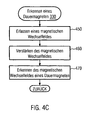
- Fig. 4C
- ein Verfahren zum Erkennen eines Dauermagneten gemäß einer weiteren Ausführungsform der vorliegenden Erfindung.
- Zur Verdeutlichung der Erfindung werden nun die beigefügten Zeichnungen näher erläutert. Die folgende Beschreibung der Zeichnungen geht dabei von Ausführungsformen der Erfindung aus, jedoch ist die vorliegende Erfindung nicht auf die einzelnen Ausführungsformen beschränkt. Insbesondere ist die vorliegende Erfindung im Detail für das Fußballspiel erläutert, ist aber in ihrer Anwendung nicht auf diese spezielle Ballsportart beschränkt.
-
Figur 1 zeigt eine schematische Darstellung eines Systems und einer Vorrichtung zur Erfassung eines Magnetfeldes und einem Spielball gemäß einer Ausführungsform der vorliegenden Erfindung. Das System umfasst den Spielball 100, der mit mindestens einem Dauermagneten ausgestattet ist.Figur 1 zeigt einen ersten Dauermagneten 110A, der vorzugsweise in der Spielballmitte angebracht ist. Dies kann über eine Einspannung mit Fäden oder Federn bewerkstelligt werden. In einer anderen Ausführungsform wird der Dauermagnet 110A durch einen Weichschaum, der das Innere des Balles ausfüllt, an seiner zentralen Position gehalten. - In einer alternativen Ausführungsform werden zwei oder mehr Dauermagneten in der Ballwand integriert oder befestigt. Dies kann zum Beispiel während des Herstellens einer Innenschale oder inneren Hülle des Spielballes bewerkstelligt werden. Die vorliegende Erfindung ist aber weder auf diese Anbringungsmethoden noch auf die beschriebene und gezeigte Anzahl von Dauermagneten beschränkt.
- Die Dauermagnete in dem Spielball dienen zum Erzeugen eines Magnetfeldes mit einer vorzugsweise vorbestimmten Reichweite. Die gewählte Reichweite kann zum Beispiel durch die Größe oder das Material des Dauermagneten bestimmt werden. Damit lässt sich sowohl die Bestimmung von direktem Ballbesitz, d. h. einem Kontakt zwischen Fußballschuh und Spielball, als auch eine Bestimmung durch mehrere Fußballschuhe in der Nähe des Spielballes ermöglichen, um so Rückschlüsse auf den so genannten Ballbesitz einzelner Spieler zu erlauben. Durch die Reichweite der Dauermagneten können Vorrichtungen mehrerer Spieler, die zum Beispiel versuchen, in Ballbesitz zu gelangen, die Distanz zu dem Ball erfassen.
- Des Weiteren ist der Einsatz von Dauermagneten besonders Kostengünstig für das gesamte System. Beispielsweise benötigt ein solcher Ball keine eigene Stromversorgung, wie es bei Magnetfeldgeneratoren der Fall ist. Zudem ist ein Dauermagnet günstiger und einfacher im Ball anzubringen als Lösungen, die elektronische Schaltkreise umfassen.
- Die
Figur 1 zeigt des Weiteren eine Vorrichtung 130 zur Erfassung des Ballbesitzes oder der Nähe zu einem Ball. Die Vorrichtung 130 ist inFigur 1 so dargestellt, dass sie sich im unmittelbaren Einflussbereich des Magnetfeldes 120 eines der Dauermagneten befindet. Durch die Zunahme der Magnetfeldstärke mit der Annäherung der Vorrichtung 130 an den Ball 100 kann die Vorrichtung 130 einen Ballbesitz ermitteln. Zum Beispiel kann die Vorrichtung 130, wie weiter unten näher erläutert, die gemessene Magnetfeldstärke mit einem Schwellenwert vergleichen und bei Überschreitung des Schwellenwertes einen Dauermagneten bzw. Ballbesitz erkennen. Gemäß einer Ausführungsform kann je nach Stärke des Dauermagneten dieser Schwellenwert so gesetzt werden, dass ein Bereich von bis zu 25 cm um den Ball als Ballbesitz interpretiert wird. - Die
Figur 2 zeigt die oben erwähnte Vorrichtung 130 detaillierter. Sie enthält den Magnetfeldsensor 210, der ein Sensorsignal in Abhängigkeit der gemessenen Magnetfeldstärke erzeugt. In einer weiteren Ausführungsform kann die Vorrichtung 130 auch mit zwei oder mehr Magnetfeldsensoren ausgestattet sein. In einer Ausführungsform der vorliegenden Erfindung enthält der Magnetfeldsensor 122 vorzugsweise ein magnetoresistives Element oder ein Hall-Element. Wird die Magnetfeldstärke mit magnetoresistiven Sensoren als magnetfeldabhängige Widerstände gemessen, können diese zu einer Brücke geschaltet werden. Das Ausgangssignal der Brücke kann mit einem Differenz-Verstärker verstärkt werden. Die Ausgangsspannung ist ein direktes Maß für die Feldstärke des gemessenen Magnetfeldes. Um bei jeder möglichen Rotationsachse des Spielballs ein auswertbares Signal zu erhalten, können zwei oder drei um jeweils 90 Grad versetzte Sensoren verwendet werden. - Alternativ kann die Feldstärke mit Hall-Sensoren gemessen werden. Hall-Sensoren erzeugen proportional zur Feldstärke eine Spannung. Diese Spannung kann mit Hilfe eines Differenz-Verstärkers verstärkt werden. Die Ausgangsspannung ist ein direktes Maß für die Feldstärke des Magnetfelds. Die Auswertung dieser Spannung kann entweder diskret über eine analoge Schaltung oder mit Hilfe einer Steuereinheit 220, beispielsweise einem Mikrocontroller, erfolgen. Um bei jeder möglichen Rotationsachse des Spielballs ein auswertbares Signal zu erhalten, können zwei oder drei um 90 Grad versetzte Sensoren verwendet werden.
- Die Steuereinheit 220, die mit dem Magnetfeldsensor zur Erfassung eines Ausgangssignals gekoppelt ist, verarbeitet das Signal weiter. In einer Ausführungsform der vorliegenden Erfindung vergleicht die Steuereinheit 220 das empfangene Signal des Magnetfeldsensors 210 mit einem Schwellenwert, um zu ermitteln, ob sich ein Dauermagnet in unmittelbarer Nähe zu dem Magnetfeldsensor 210 befindet. Diese und weitere Ausführungsformen werden unten in Bezug auf
Figuren 3 und4 näher erläutert. - Die Vorrichtung 130 kann in einer Ausführungsform der vorliegenden Erfindung auch eine Speichereinheit 225 enthalten. Dieser Speicher 225 ermöglicht es der Steuereinheit 220, Ereignisse, wie zum Beispiel das Überschreiten eines Schwellenwertes durch das Magnetfeldsensorsignal, zu speichern.
- Die
Figur 2 zeigt ebenso ein Ausgabemodul 230, was die Ausgabe der ermittelten Ereignisse ermöglicht. In einer Ausführungsform der vorliegenden Erfindung wird die Ausgabeeinheit 230 durch eine Sendeeinheit bereitgestellt. Die Sendeeinheit ist so ausgebildet, dass sie Daten zu einer zentralen Erfassungseinheit übermitteln kann. Diese zentrale Erfassungseinheit kann zum Beispiel am Spielfeldrand angeordnet sein oder an einem anderen Ort, von welchem aus Signale von Sendeeinheiten von dem gesamten Spielfeld aus empfangen werden können. Somit ist eine Übertragung von Informationen, die von der Steuereinheit erzeugt werden zu jeder Zeit während des Spiels möglich. - Alternativ werden die Ereignisse, die durch die Steuereinheit 220 erfasst werden, gespeichert, aber mittels einer Sendeeinheit 230 an die zentrale Erfassungseinheit nach Ende des Spiels oder in einer Pause übertragen. Somit kann die Sendeleistung der Sendeeinheit reduziert werden.
- In einer weiteren Ausführungsform wird das Ausgabemodul 230 durch eine kabelgebundene Schnittstelle ausgebildet. Diese ist zum Beispiel mit einer Steckverbindung 240 gekoppelt, wobei das Anschließen einer zentralen Erfassungseinheit über ein Kabel ermöglicht wird. Durch das Anschließen der Vorrichtung 130 an die zentral Erfassungseinheit kann der Inhalt des Speichers ausgelesen werden, wodurch der gesamte Spielverlauf in Hinblick auf Ballbesitz oder Nähe eines Spielers zum Spielball ermitteln werden kann.
- Die Vorrichtung 130 enthält ferner eine Energiequelle 250. Die Energiequelle 250 ist gemäß einem Ausführungsbeispiel der vorliegenden Erfindung eine Batterie. Dabei wird die Vorrichtung 130 beispielsweise über eine Lithiumbatterie versorgt. Die Kapazität der Batterie ist dabei so ausgelegt, dass die Funktionalität der Elektronik in der Vorrichtung 130 über eine bestimmte Anzahl von mehreren hundert oder tausend Betriebsstunden sichergestellt ist. Vorzugsweise kann die Energiequelle 250 als austauschbare Einheit vorgesehen sein, die ohne größeren Aufwand vom Anwender ausgewechselt werden kann.
-
Figur 3 zeigt ein Flussdiagramm zur Erläuterung eines Verfahrens zur Erfassung eines Ballbesitzes oder einer unmittelbaren Nähe zwischen Fußballschuh und Spielball 100. - Das System 130 wird bevorzugt an einem Kleidungsstück eines Spielers angebracht. Zum Beispiel kann das System 130 in einem Fußballschuh integriert sein oder an einem Schienbeinschoner befestigt werden. Nähert sich der Spieler, und somit das System 130, dem Ball, kann der Magnetfeldsensor 210 ein Magnetfeld erfassen, Schritt 310. Es wird ein Erfassungssignal von dem Sensor 210 an die Steuereinheit 220 weitergegeben. Durch das Erfassen des Magnetfeldes misst die Steuereinheit 220 in Schritt 320 die Magnetfeldstärke, die in Form von Sensorsignalen des Magnetfeldsensors 210 abgegriffen werden können. Die Vorrichtung 130 ist somit in den Einflussbereich des Dauermagneten im Spielball gelangt. Zum Beispiel hat sich ein Spieler dem Ball angenähert und versucht, in Ballbesitz zu gelangen.
- Als Weiteres erkennt die Steuereinheit 220 in Schritt 330 den Dauermagneten bzw. das Magnetfeld des Dauermagneten. Die Verfahren der
Figuren 4A bis 4C zeigen drei Ausführungsformen des Schrittes 330. Diese drei Verfahren können auch verwendet werden, um festzustellen, wie nah der Spieler dem Ball gekommen ist. - In einer Ausführungsform der vorliegenden Erfindung speichert die Steuervorrichtung 220 in Schritt 340 Informationen zu dem oben genannten Ereignis der Ballannäherung. Diese Informationen können zum Beispiel die Magnetfeldstärke des Dauermagneten im Spielball umfassen.
- In einer weiteren Ausführungsform der vorliegenden Erfindung kann in einem Schritt 333 ein Zeitstempel generiert werden, wenn die Steuereinheit 220 einen Dauermagneten erkennt. Dieser Zeitstempel kann zusammen mit den Informationen bezüglich eines Erkennungsereignisses abgespeichert werden. Sind Informationen bezüglich des Ballbesitzes mit solch einem Zeitstempel versehen, kann zum Beispiel ausgewertet werden, ob eine Ballweitergabe erfolgreich ausgeführt wurde. Beispielsweise kann bei einer Auswertung festgestellt werden, dass das zeitlich nächste Ereignis durch einen anderen Spieler ausgelöst wurde, der zur gleichen Mannschaft gehört wie der Spieler, der das erste Ereignis auslöste. Somit ist die Ballübergabe innerhalb einer Mannschaft erfolgreich verlaufen.
- Ebenso können die Ergebnisse von zwei Systemen 130 dahingehend ausgewertet werden, dass ein Spieler einer gegnerischen Mannschaft in Ballbesitz gelangte. Dafür kann der in Schritt 333 generierte Zeitstempel zusammen mit dem Ereignis in Schritt 340 gespeichert werden.
- In einer anderen Ausführungsform wird das Ereignis noch nicht gespeichert, sondern mit der Erfassung des Magnetfeldes und der Messung der Magnetfeldstärke fortgefahren. Wie in
Figur 3 gezeigt, gibt es eine optionale Zeitmessung 336, die die Dauer eines Ereignisses misst. In anderen Worten, solange ein Dauermagnet in Schritt 330 erkannt wird, wird mit der Zeitmessung fortgefahren, bis eine Veränderung bei Schritt 330 festgestellt wird. Anschlie-βend kann das Ereignis zusammen mit der Dauer gespeichert werden. Beispielsweise wird die Information bezüglich des Ereignisses mit einer Anfangszeit und einer Endzeit versehen und anschließend gespeichert. - Wie oben erwähnt, gibt es mehrere Ausführungsformen, wie die Informationen bezüglich Ballbesitzereignissen an eine zentrale Auswertungseinheit übermittelt werden. In einer ersten Ausführungsform werden die gespeicherten Daten in Schritt 350 an die zentrale Auswertungseinheit ausgegeben. Diese Ausgabe kann zum Beispiel über eine Sendeeinheit an einen entsprechenden Empfänger, der mit der Auswertungseinheit gekoppelt ist, übermittelt werden. Dies ermöglicht zum Beispiel, dass ein Spieler in einer Pause oder nach Beendigung des Spiels seinen Schuh in die Nähe des Empfängers bringt, wodurch das Senden der Sendeeinheit ausgelöst werden kann.
- In einer weiteren Ausführungsform wird die Übertragung mittels eines Kabels durchgeführt, wozu die Vorrichtung 130 über die Schnittstelle 240 und einem Kabel an die zentrale Auswertungseinheit angeschlossen wird. Diese Ausführungsform ermöglicht eine energiesparendere und somit auch kleinere Ausführungsform, als wenn die Vorrichtung 130 eine eigenständige Sendeinheit beinhalten würde.
- In einer anderen Ausführungsform werden die Ereignisse nicht gespeichert, sondern sofort nach der Generierung des Zeitstempels in Schritt 333 an die zentrale Auswertungseinheit übertragen, Schritt 335. Diese Ausführungsform wiederum ermöglicht eine einfachere Bauart, weil das System 130 keinen Speicher 225 benötigt. In jedem Fall beginnt die Erfassung des Magnetfeldes in Schritt 310 wieder erneut, sobald die Daten in Schritt 335 übertragen oder in Schritt 350 ausgegeben wurden.
- Bezug nehmend auf die
Figuren 4A bis 4C werden nun verschiedene Ausführungsformen erläutert, wie die Nähe eines Dauermagneten erkannt werden kann. -
Figur 4A zeigt ein Verfahren zum Erkennen eines Dauermagneten, wenn dieser sich in unmittelbarer Nähe zu der Vorrichtung 130 befindet. Dieses Verfahren eignet sich zum Beispiel für die Bestimmung des Ballbesitzes, da durch geeignete Parameter Entfernungen bis 25 cm zwischen Spielball und Fußballschuh ermittelt werden können. In einem ersten Schritt 410 wird die Magnetfeldstärke mit einem Schwellenwert verglichen. Die Magnetfeldstärke wurde, wie inFigur 3 gezeigt, in Schritt 320 mithilfe des Magnetfeldsensors 210 gemessen. Je nach verwendetem Dauermagneten kann der Schwellenwert beispielsweise so voreingestellt sein, dass ein Überschreiten des Schwellenwertes einer Distanz zum Ball von weniger als 25 cm entspricht. In einem weiteren Schritt 420 wird ein Dauermagnet dadurch erkannt, dass die gemessene Magnetfeldstärke den Schwellenwert übersteigt. Diese Information wird durch die Steuereinheit 220 entsprechend verarbeitet. Zum Beispiel kann diesem Ereignis eine bestimmte Identifizierungsnummer zugeordnet werden, die entweder direkt an eine zentrale Erfassungseinheit übermittelt wird oder in dem Speicher 225 gespeichert wird. - Gemäß dem Verfahren der
Figur 4B wird das Erkennen eines Dauermagnets unter Berücksichtigung des Erdmagnetfeldes ermittelt. In Schritt 430 wird das Erdmagnetfeld erfasst und die Stärke des Erdmagnetfeldes gemessen. Dieser Schritt kann zum Beispiel erfolgen, wenn ein Spieler das Spielfeld betritt. Für gewöhnlich ist das Erdmagnetfeld auf dem gesamten Spielfeld gleich stark. Die Vorrichtung 130 kann zum Beispiel auch mit einer Eingabetaste ausgestattet sein, wodurch ein Spieler die Erfassung des Erdmagnetfeldes auslösen kann. Auf jeden Fall ist es notwendig, dass sich der Spieler nicht in der Nähe eines Balles mit Dauermagneten aufhält. - In Schritt 440 wird nun ermittelt, ob sich die Stärke des Erdmagnetfeldes verändert hat. Da hierfür natürliche Ursachen ausgeschlossen werden, muss eine solche Veränderung durch einen Magneten verursacht worden sein. Die Steuereinheit 220 kann somit durch Vergleichen der in Schritt 320 gemessenen Magnetfeldstärke mit der Erdmagnetfeldstärke feststellen, ob sich der Spieler in der Nähe des Balles befindet, aber nicht so nah am Ball ist, wie in Bezug auf
Figur 4A beschrieben. - Das Verfahren aus
Figur 4B eignet sich zum Beispiel für Distanzmessungen bis zu 50 cm vom Ball. Diese Unterscheidung zwischen dem Erkennen eines Dauermagneten im unmittelbaren Bereich (sieheFigur 4A ) und in einem etwas weiteren Bereich (sieheFigur 4B ) eignet sich zum Beispiel zum Auswerten einer Ballabnahme zwischen zwei Spielern gegnerischer Mannschaften. In solchen Spielsituationen ist es häufig der Fall, dass mehrere Spieler sich in unmittelbarer Nähe des Balles befinden. Welcher Fußballschuh sich zu welchem Zeitpunkt am Ball befunden hat, kann somit Vorteilhafterweise ausgewertet werden. Entsprechend einer weiteren Ausführungsform der vorliegenden Erfindung kann die Nähe zu einem Dauermagneten auch wie folgt detektiert werden. In Schritt 450 ermittelt die Steuereinheit 220, dass der Magnetfeldsensor 210 ein magnetisches Wechselfeld erfasst hat. Beispielsweise kann hierfür in dem Magnetfeldsensor 210 mindestens ein Kondensator vorgesehen werden. Dadurch ist es möglich, dass die Messausgänge des Magnetfeldsensors über den mindestens einen Kondensator so entkoppelt werden, dass nur Wechselfeldern zu den Verstärkern durchgelassen werden. Durch den vergrößerten Verstärkungsfaktor können auch schwächere Wechselfelder erkannt werden. Anschließend wird das magnetische Wechselfeld verstärkt, Schritt 460, um eine Auswertung zu ermöglichen. - Die Steuervorrichtung 220 ermittelt nun in Schritt 470, dass sich das magnetische Wechselfeld eines Dauermagneten in der näheren Umgebung befindet. Da sich in den meisten Ballsportarten der Ball rollend oder drehend fortbewegt, gibt der Ball 100, der mit den Dauermagneten 110 ausgestattet ist, immer ein magnetisches Wechselfeld ab. Dieses Wechselfeld kann aufgrund der Verstärkung gut erkannt werden. Das Verfahren nach
Figur 4C eignet sich zum Beispiel für Entfernungen zwischen Spieler und Ball von bis zu einem Meter. Wie oben erwähnt, können solche Ereignisse Vorteilhafterweise genutzt werden, um festzustellen, ob ein sich annähernder Spieler erfolgreich einem Gegner den Ball abgenommen hat. Ein solches Ereignis kann mit einer entsprechenden Identifikationsnummer durch die Steuereinheit 220 versehen werden. Damit ist die Auswertung der Informationen einfacher, wenn je nach Verfahren derFiguren 4A bis 4C verschiedene Identifikationsnummern verwendet werden. - Gemäß der vorliegenden Erfindung ist es über eine Auswertung der Ballbesitzinformation möglich, detaillierte Informationen über die am Spielbetrieb teilnehmenden Spieler zu gewinnen. Dies erlaubt eine Analyse der einzelnen Spieler durch die Auswertung der Gesamtzeiten, in denen sich ein Spieler in Ballbesitz befindet. Diese Daten sind einerseits für Hobbyspieler interessant sowie andererseits für Trainer von professionellen Spielern von Interesse.
Claims (15)
- Vorrichtung (130) zur Ballbesitzerkennung mit Mitteln zum Erfassen eines Magnetfeldes in einem Spielgerät (100) einer Ballsportart, wobei das Magnetfeld durch mindestens einen Dauermagneten (110) in dem Spielgerät erzeugt wird, wobei die Vorrichtung (130) einem Spieler der Ballsportart zugeordnet werden kann und die Mittel zur Magnetfelderfassung umfassen:einen Magnetfeldsensor (210); undeine Steuereinheit (220), die mit dem Magnetfeldsensor gekoppelt ist, um ein Sensorsignal von dem Magnetfeldsensor zu erhalten, und die eingerichtet ist zum Erkennen, ob das Sensorsignal durch das Magnetfeld des mindestens einen Dauermagneten in dem Spielgerät verursacht wurde, und zum Ausgeben von Informationen über das Erkennen.
- Vorrichtung gemäß Anspruch 1, wobei der Magnetfeldsensor das Magnetfeld des mindestens einen Dauermagneten erfasst und die Stärke des Magnetfeldes misst.
- Vorrichtung gemäß Anspruch 2, wobei der Magnetfeldsensor des Weiteren das Erdmagnetfeld erfasst und die Erdmagnetfeldstärke misst, und wobei die Steuereinheit das Magnetfeld des mindestens einen Dauermagneten aufgrund einer Veränderung der Erdmagnetfeldstärke durch den mindestens einen Dauermagneten erkennt.
- Vorrichtung gemäß Anspruch 2, wobei der Magnetfeldsensor ausgebildet ist, ein magnetisches Wechselfeld zu erfassen, das durch Rotation des mindestens einen Dauermagneten im Spielgerät erzeugt wird, und wobei die Steuereinheit eingerichtet ist, Informationen über das Erkennen des magnetischen Wechselfeldes auszugeben.
- Vorrichtung gemäß Anspruch 4, wobei der Magnetfeldsensor mindestens einen Messausgang umfasst, und wobei der mindestens eine Messausgang über mindestens einen Kondensator entkoppelt ist.
- Vorrichtung gemäß einem der Ansprüche 1 bis 5, wobei der Magnetfeldsensor mindestens einen Verstärker umfasst.
- Vorrichtung gemäß einem der Ansprüche 1 bis 6, wobei die Steuereinheit eingerichtet ist, das Erkennen des Magnetfeldes zusammen mit einem Zeitstempel, der zugehörig zu dem Zeitpunkt des Erkennens ist, auszugeben.
- Vorrichtung gemäß einem der Ansprüche 1 bis 7, wobei die Mittel zur Magnetfelderfassung des Weiteren umfassen:eine Speichereinheit (225);wobei die Steuereinheit des Weiteren eingerichtet ist, die ausgegebenen Informationen in der Speichereinheit zu speichern.
- Vorrichtung gemäß Anspruch 8, wobei die Vorrichtung eine Ausgabeeinheit (230) umfasst, die ein Auslesen der Speichereinheit ermöglicht.
- Vorrichtung gemäß einem der Ansprüche 1 bis 7, wobei die Mittel zur Magnetfelderfassung des Weiteren umfassen:eine Sendeeinheit;wobei die Steuereinheit des Weiteren eingerichtet ist, die ausgegebenen Informationen mittels der Sendeeinheit an eine zentrale Auswertungseinheit zu übermitteln.
- Vorrichtung gemäß Anspruch 9, wobei die Vorrichtung in oder an einem Kleidungsstück des Spielers angeordnet ist, das sich während der Ausübung der Ballsportart bevorzugt in der Nähe des Balls befindet.
- Verfahren zur Ballbesitzerkennung durch Erfassen eines Magnetfeldes in einem Spielgerät (100) einer Ballsportart, wobei das Magnetfeld durch mindestens einen Dauermagneten (110) in dem Spielgerät erzeugt wird, und wobei das Verfahren umfasst:Erfassen (310) eines Magnetfeldes;Messen (320) der Magnetfeldstärke des erfassten Magnetfeldes;Erkennen (330), ob das Magnetfeld durch den mindestens einen Dauermagneten in dem Spielgerät verursacht wurde; undAusgeben (350) von Informationen über das Erkennen.
- Verfahren gemäß Anspruch 12, wobei Erfassen und Messen umfasst:Erfassen des Magnetfeldes des mindestens einen Dauermagneten und Messen (320) der zugehörigen Magnetfeldstärke, wobei Erkennen das Vergleichen (410) der gemessenen Magnetfeldstärke mit einem Schwellenwert umfasst;Erfassen (430) des Erdmagnetfeldes und Messen (430) der Erdmagnetfeldstärke, wobei Erkennen das Erkennen (440) einer Veränderung der Erdmagnetfeldstärke umfasst; oderErfassen (450) eines magnetischen Wechselfeldes des mindestens einen Dauermagneten in dem Spielgerät und Messen der Stärke des magnetischen Wechselfeldes, wobei Erkennen das Erkennen (470) des magnetischen Wechselfeldes umfasst.
- Verfahren gemäß einem der Ansprüche 12 oder 13, des Weiteren umfassend:Speichern der ausgegebenen Informationen und/oder Übermitteln der ausgegebenen Informationen an eine zentrale Auswertungseinheit.
- Anordnung mit einem System (130) zur Ballbesitzerkennung, das eingerichtet ist zur Durchführung des Verfahrens gemäß einem der Ansprüche 12 bis 14, und mit einem Spielball, der mindestens einen Dauermagneten enthält.
Applications Claiming Priority (3)
| Application Number | Priority Date | Filing Date | Title |
|---|---|---|---|
| US12253608P | 2008-12-15 | 2008-12-15 | |
| DE102008062276A DE102008062276B3 (de) | 2008-12-15 | 2008-12-15 | System und Verfahren zur Ballbesitzerkennung mithilfe eines passiven Feldes |
| PCT/EP2009/008994 WO2010075963A2 (de) | 2008-12-15 | 2009-12-15 | System und verfahren zur ballbesitzerkennung mithilfe passiver felderzeugung |
Publications (2)
| Publication Number | Publication Date |
|---|---|
| EP2366121A2 EP2366121A2 (de) | 2011-09-21 |
| EP2366121B1 true EP2366121B1 (de) | 2012-09-19 |
Family
ID=42235306
Family Applications (1)
| Application Number | Title | Priority Date | Filing Date |
|---|---|---|---|
| EP09806079A Not-in-force EP2366121B1 (de) | 2008-12-15 | 2009-12-15 | System und verfahren zur ballbesitzerkennung mit hilfe passiver felderzeugung |
Country Status (5)
| Country | Link |
|---|---|
| US (1) | US20100201352A1 (de) |
| EP (1) | EP2366121B1 (de) |
| DE (1) | DE102008062276B3 (de) |
| ES (1) | ES2394392T3 (de) |
| WO (1) | WO2010075963A2 (de) |
Families Citing this family (32)
| Publication number | Priority date | Publication date | Assignee | Title |
|---|---|---|---|---|
| DE102007015493A1 (de) * | 2007-03-30 | 2008-10-02 | Cairos Technologies Ag | Bewegungsbereich für einen mobilen Gegenstand und Auswertungsvorrichtung zum Feststellen einer Position eines mobilen Gegenstands |
| US8702430B2 (en) | 2007-08-17 | 2014-04-22 | Adidas International Marketing B.V. | Sports electronic training system, and applications thereof |
| US8221290B2 (en) | 2007-08-17 | 2012-07-17 | Adidas International Marketing B.V. | Sports electronic training system with electronic gaming features, and applications thereof |
| US8360904B2 (en) | 2007-08-17 | 2013-01-29 | Adidas International Marketing Bv | Sports electronic training system with sport ball, and applications thereof |
| DE102007048818A1 (de) * | 2007-09-19 | 2009-04-02 | Cairos Technologies Ag | Automatische Positionsbestimmung eines Objektes, insbesondere eines Fußballs |
| US8450997B2 (en) * | 2009-04-28 | 2013-05-28 | Brown University | Electromagnetic position and orientation sensing system |
| US8839871B2 (en) | 2010-01-15 | 2014-09-23 | Halliburton Energy Services, Inc. | Well tools operable via thermal expansion resulting from reactive materials |
| CA2949476C (en) * | 2010-11-19 | 2020-06-16 | Isolynx, Llc | Associative object tracking systems and methods |
| US8474533B2 (en) | 2010-12-07 | 2013-07-02 | Halliburton Energy Services, Inc. | Gas generator for pressurizing downhole samples |
| US8757274B2 (en) | 2011-07-01 | 2014-06-24 | Halliburton Energy Services, Inc. | Well tool actuator and isolation valve for use in drilling operations |
| US20130048290A1 (en) * | 2011-08-29 | 2013-02-28 | Halliburton Energy Services, Inc. | Injection of fluid into selected ones of multiple zones with well tools selectively responsive to magnetic patterns |
| US9151138B2 (en) | 2011-08-29 | 2015-10-06 | Halliburton Energy Services, Inc. | Injection of fluid into selected ones of multiple zones with well tools selectively responsive to magnetic patterns |
| US9506324B2 (en) | 2012-04-05 | 2016-11-29 | Halliburton Energy Services, Inc. | Well tools selectively responsive to magnetic patterns |
| US9504414B2 (en) | 2012-04-13 | 2016-11-29 | Adidas Ag | Wearable athletic activity monitoring methods and systems |
| US9257054B2 (en) | 2012-04-13 | 2016-02-09 | Adidas Ag | Sport ball athletic activity monitoring methods and systems |
| US9737261B2 (en) | 2012-04-13 | 2017-08-22 | Adidas Ag | Wearable athletic activity monitoring systems |
| US10922383B2 (en) | 2012-04-13 | 2021-02-16 | Adidas Ag | Athletic activity monitoring methods and systems |
| US9169705B2 (en) | 2012-10-25 | 2015-10-27 | Halliburton Energy Services, Inc. | Pressure relief-assisted packer |
| US9587486B2 (en) | 2013-02-28 | 2017-03-07 | Halliburton Energy Services, Inc. | Method and apparatus for magnetic pulse signature actuation |
| US9587487B2 (en) | 2013-03-12 | 2017-03-07 | Halliburton Energy Services, Inc. | Wellbore servicing tools, systems and methods utilizing near-field communication |
| US9500464B2 (en) | 2013-03-12 | 2016-11-22 | Adidas Ag | Methods of determining performance information for individuals and sports objects |
| US9284817B2 (en) | 2013-03-14 | 2016-03-15 | Halliburton Energy Services, Inc. | Dual magnetic sensor actuation assembly |
| US20150075770A1 (en) | 2013-05-31 | 2015-03-19 | Michael Linley Fripp | Wireless activation of wellbore tools |
| US9752414B2 (en) | 2013-05-31 | 2017-09-05 | Halliburton Energy Services, Inc. | Wellbore servicing tools, systems and methods utilizing downhole wireless switches |
| US9482072B2 (en) | 2013-07-23 | 2016-11-01 | Halliburton Energy Services, Inc. | Selective electrical activation of downhole tools |
| MX375322B (es) | 2014-03-24 | 2025-03-06 | Halliburton Energy Services Inc | Herramientas de pozo que tienen protección magnética para sensor magnético. |
| US9849361B2 (en) | 2014-05-14 | 2017-12-26 | Adidas Ag | Sports ball athletic activity monitoring methods and systems |
| US10523053B2 (en) | 2014-05-23 | 2019-12-31 | Adidas Ag | Sport ball inductive charging methods and systems |
| US9710711B2 (en) | 2014-06-26 | 2017-07-18 | Adidas Ag | Athletic activity heads up display systems and methods |
| AU2014412711B2 (en) | 2014-11-25 | 2018-05-31 | Halliburton Energy Services, Inc. | Wireless activation of wellbore tools |
| US11562417B2 (en) | 2014-12-22 | 2023-01-24 | Adidas Ag | Retail store motion sensor systems and methods |
| WO2019166850A1 (en) * | 2018-02-27 | 2019-09-06 | Axiamo Gmbh | Ball detection for a ball game |
Citations (1)
| Publication number | Priority date | Publication date | Assignee | Title |
|---|---|---|---|---|
| DE102005017257A1 (de) * | 2005-04-14 | 2007-04-12 | Peter Lehnert | Ball und Vorrichtung zur Überwachung der Ballposition bei Ballspielen |
Family Cites Families (17)
| Publication number | Priority date | Publication date | Assignee | Title |
|---|---|---|---|---|
| US8280682B2 (en) * | 2000-12-15 | 2012-10-02 | Tvipr, Llc | Device for monitoring movement of shipped goods |
| WO2001037945A2 (en) * | 1999-11-24 | 2001-05-31 | David Sitrick | System for tracking playing device having detectable signature |
| US6597128B2 (en) * | 2001-10-03 | 2003-07-22 | Hubbell Incorporated | Remote discharge lamp ignition circuitry |
| US6963301B2 (en) * | 2002-08-19 | 2005-11-08 | G-Track Corporation | System and method for near-field electromagnetic ranging |
| DE202004006680U1 (de) * | 2004-04-27 | 2005-03-17 | Schroeder Heinrich | Vorrichtungen zur Erfassung und Bewertung von Ereignissen und Ergebnissen bei Fußball-Spielen ausserhalb der Spielregeln und zur Sicherheit |
| US20060178235A1 (en) * | 2005-02-05 | 2006-08-10 | Avaya Technology Corp. | Apparatus and method for determining participant contact with a sports object |
| DE102005036355A1 (de) * | 2005-07-29 | 2007-02-01 | Cairos Technologies Ag | Verfahren zur Erfassung der Kraft- und Bewegungsverhältnisse an einem Spielgerät |
| KR100735419B1 (ko) * | 2005-12-02 | 2007-07-04 | 삼성전자주식회사 | 발동작을 이용한 휴대기기 조작 시스템 및 방법 |
| US7795861B2 (en) * | 2006-05-02 | 2010-09-14 | Cairos Technologies Ag | Method and apparatus for controlling a movable object for localization within a positioning area |
| US7719469B2 (en) * | 2006-10-06 | 2010-05-18 | Cairos Technologies Ag | Device and method for position measurement by means of linear doppler shifts generated |
| DE102006047376B3 (de) * | 2006-10-06 | 2008-04-10 | Cairos Technologies Ag | Konzept zur Torentscheidung mittels Magnetfeldern |
| US8079925B2 (en) * | 2006-10-12 | 2011-12-20 | Cairos Technologies Ab | Concept for activating a game device |
| DE102007001820B3 (de) * | 2006-10-12 | 2008-01-24 | Cairos Technologies Ag | Konzept zur Erkennung eines Kontakts mit einem Spielgerät |
| EP2025372B1 (de) * | 2007-08-15 | 2013-03-27 | Catapult Innovations Pty Ltd | Ballverfolgung im Sport |
| JP2009049662A (ja) * | 2007-08-17 | 2009-03-05 | Toshiba Corp | 情報処理装置 |
| GB2462624A (en) * | 2008-08-14 | 2010-02-17 | Arthur Stewart Dunlop | Goal detection apparatus |
| US8172722B2 (en) * | 2008-12-05 | 2012-05-08 | Nike, Inc. | Athletic performance monitoring systems and methods in a team sports environment |
-
2008
- 2008-12-15 DE DE102008062276A patent/DE102008062276B3/de not_active Expired - Fee Related
-
2009
- 2009-12-15 EP EP09806079A patent/EP2366121B1/de not_active Not-in-force
- 2009-12-15 ES ES09806079T patent/ES2394392T3/es active Active
- 2009-12-15 US US12/638,793 patent/US20100201352A1/en not_active Abandoned
- 2009-12-15 WO PCT/EP2009/008994 patent/WO2010075963A2/de not_active Ceased
Patent Citations (1)
| Publication number | Priority date | Publication date | Assignee | Title |
|---|---|---|---|---|
| DE102005017257A1 (de) * | 2005-04-14 | 2007-04-12 | Peter Lehnert | Ball und Vorrichtung zur Überwachung der Ballposition bei Ballspielen |
Also Published As
| Publication number | Publication date |
|---|---|
| DE102008062276B3 (de) | 2010-09-09 |
| ES2394392T3 (es) | 2013-01-31 |
| WO2010075963A3 (de) | 2011-05-19 |
| US20100201352A1 (en) | 2010-08-12 |
| WO2010075963A2 (de) | 2010-07-08 |
| EP2366121A2 (de) | 2011-09-21 |
Similar Documents
| Publication | Publication Date | Title |
|---|---|---|
| DE102008062276B3 (de) | System und Verfahren zur Ballbesitzerkennung mithilfe eines passiven Feldes | |
| EP1984082B1 (de) | Konzept zur erkennung eines kontakts mit einem spielgerät | |
| EP2200723B1 (de) | Erfassen und bereitstellen von spielerinformationen mit spielerseitigem sensor | |
| EP1909925B1 (de) | Vorrichtung und Verfahren zum Messen einer auf ein bewegliches Spielgerät ausgeübten Schusskraft | |
| EP1646432B1 (de) | Messanordnung | |
| WO2010054848A1 (de) | Erfassen und bereitstellen von spielerinformationen mit mehrfachsensorik | |
| DE102005027668A1 (de) | Verfahren im Zusammenhang mit einem Armbandcomputer und ein Armbandcomputersystem | |
| WO2008043443A2 (de) | Vorrichtung und verfahren zur torentscheidung mittels magnetfelder | |
| WO2013029191A1 (de) | Vorrichtung zur erfassung von tennis-spieldaten | |
| EP1976601B1 (de) | Konzept zur aktivierung eines spielgeräts | |
| DE10029456A1 (de) | Verfahren zur Eichung eines Sensorsystems | |
| EP2310099A1 (de) | System und verfahren zur automatisierten analyse eines wettkampfverlaufes | |
| EP3908377B1 (de) | Verfahren und system zum golftraining | |
| DE102016105842B3 (de) | Druck- und Positionsmesssystem für manuell betätigbare Einrichtungen mit einem Handgriff | |
| DE20180368U1 (de) | Übungs- und Trainingseinrichtung | |
| DE102021112688B4 (de) | Vorrichtung und Verfahren zur Ermittlung der Eignung eines bestimmten Ansitzes für die Jagd auf Wildtiere am Tag der Jagd | |
| WO2014090263A1 (de) | Verfahren zur bestimmung des von einer person zurückgelegten weges | |
| EP1904192A1 (de) | Torlaufstange für den skisport | |
| DE102004034469A1 (de) | Sensorik zum Erkennen von Bewegungsabläufen und Feedbackanordnung | |
| DE102024112920A1 (de) | Überwachung eines Rückschlagsport-Spiels | |
| DE4327433A1 (de) | Sensorische Sport-Trefferfläche | |
| DE102015121854A1 (de) | Verfahren und System zum Livebestimmen eines Sportgeräts | |
| DE202007009802U1 (de) | Anordnung, umfassend ein Spielfeld und mindestens eine Spielfigur | |
| DE102012021998A1 (de) | Vorrichtung und Verfahren zur Darstellung der Güte einer Bewegung eines Sportgeräts und Sportgerät | |
| DE202012010726U1 (de) | Vorrichtung zur Darstellung der Güte einer Bewegung eines Sportgeräts und Sportgerät |
Legal Events
| Date | Code | Title | Description |
|---|---|---|---|
| PUAI | Public reference made under article 153(3) epc to a published international application that has entered the european phase |
Free format text: ORIGINAL CODE: 0009012 |
|
| 17P | Request for examination filed |
Effective date: 20110407 |
|
| AK | Designated contracting states |
Kind code of ref document: A2 Designated state(s): AT BE BG CH CY CZ DE DK EE ES FI FR GB GR HR HU IE IS IT LI LT LU LV MC MK MT NL NO PL PT RO SE SI SK SM TR |
|
| DAX | Request for extension of the european patent (deleted) | ||
| GRAP | Despatch of communication of intention to grant a patent |
Free format text: ORIGINAL CODE: EPIDOSNIGR1 |
|
| RIC1 | Information provided on ipc code assigned before grant |
Ipc: G01V 3/08 20060101AFI20120507BHEP Ipc: A63B 24/00 20060101ALI20120507BHEP Ipc: A63B 43/00 20060101ALI20120507BHEP |
|
| GRAS | Grant fee paid |
Free format text: ORIGINAL CODE: EPIDOSNIGR3 |
|
| GRAA | (expected) grant |
Free format text: ORIGINAL CODE: 0009210 |
|
| AK | Designated contracting states |
Kind code of ref document: B1 Designated state(s): AT BE BG CH CY CZ DE DK EE ES FI FR GB GR HR HU IE IS IT LI LT LU LV MC MK MT NL NO PL PT RO SE SI SK SM TR |
|
| REG | Reference to a national code |
Ref country code: GB Ref legal event code: FG4D Free format text: NOT ENGLISH |
|
| REG | Reference to a national code |
Ref country code: CH Ref legal event code: EP |
|
| REG | Reference to a national code |
Ref country code: IE Ref legal event code: FG4D Free format text: LANGUAGE OF EP DOCUMENT: GERMAN |
|
| REG | Reference to a national code |
Ref country code: AT Ref legal event code: REF Ref document number: 576288 Country of ref document: AT Kind code of ref document: T Effective date: 20121015 |
|
| REG | Reference to a national code |
Ref country code: DE Ref legal event code: R096 Ref document number: 502009004858 Country of ref document: DE Effective date: 20121115 |
|
| PG25 | Lapsed in a contracting state [announced via postgrant information from national office to epo] |
Ref country code: FI Free format text: LAPSE BECAUSE OF FAILURE TO SUBMIT A TRANSLATION OF THE DESCRIPTION OR TO PAY THE FEE WITHIN THE PRESCRIBED TIME-LIMIT Effective date: 20120919 Ref country code: NO Free format text: LAPSE BECAUSE OF FAILURE TO SUBMIT A TRANSLATION OF THE DESCRIPTION OR TO PAY THE FEE WITHIN THE PRESCRIBED TIME-LIMIT Effective date: 20121219 Ref country code: LT Free format text: LAPSE BECAUSE OF FAILURE TO SUBMIT A TRANSLATION OF THE DESCRIPTION OR TO PAY THE FEE WITHIN THE PRESCRIBED TIME-LIMIT Effective date: 20120919 Ref country code: HR Free format text: LAPSE BECAUSE OF FAILURE TO SUBMIT A TRANSLATION OF THE DESCRIPTION OR TO PAY THE FEE WITHIN THE PRESCRIBED TIME-LIMIT Effective date: 20120919 |
|
| REG | Reference to a national code |
Ref country code: ES Ref legal event code: FG2A Ref document number: 2394392 Country of ref document: ES Kind code of ref document: T3 Effective date: 20130131 |
|
| REG | Reference to a national code |
Ref country code: NL Ref legal event code: VDEP Effective date: 20120919 |
|
| REG | Reference to a national code |
Ref country code: LT Ref legal event code: MG4D Effective date: 20120919 |
|
| PG25 | Lapsed in a contracting state [announced via postgrant information from national office to epo] |
Ref country code: SI Free format text: LAPSE BECAUSE OF FAILURE TO SUBMIT A TRANSLATION OF THE DESCRIPTION OR TO PAY THE FEE WITHIN THE PRESCRIBED TIME-LIMIT Effective date: 20120919 Ref country code: LV Free format text: LAPSE BECAUSE OF FAILURE TO SUBMIT A TRANSLATION OF THE DESCRIPTION OR TO PAY THE FEE WITHIN THE PRESCRIBED TIME-LIMIT Effective date: 20120919 Ref country code: SE Free format text: LAPSE BECAUSE OF FAILURE TO SUBMIT A TRANSLATION OF THE DESCRIPTION OR TO PAY THE FEE WITHIN THE PRESCRIBED TIME-LIMIT Effective date: 20120919 Ref country code: GR Free format text: LAPSE BECAUSE OF FAILURE TO SUBMIT A TRANSLATION OF THE DESCRIPTION OR TO PAY THE FEE WITHIN THE PRESCRIBED TIME-LIMIT Effective date: 20121220 |
|
| PGFP | Annual fee paid to national office [announced via postgrant information from national office to epo] |
Ref country code: IT Payment date: 20121231 Year of fee payment: 4 |
|
| PG25 | Lapsed in a contracting state [announced via postgrant information from national office to epo] |
Ref country code: RO Free format text: LAPSE BECAUSE OF FAILURE TO SUBMIT A TRANSLATION OF THE DESCRIPTION OR TO PAY THE FEE WITHIN THE PRESCRIBED TIME-LIMIT Effective date: 20120919 Ref country code: NL Free format text: LAPSE BECAUSE OF FAILURE TO SUBMIT A TRANSLATION OF THE DESCRIPTION OR TO PAY THE FEE WITHIN THE PRESCRIBED TIME-LIMIT Effective date: 20120919 Ref country code: CZ Free format text: LAPSE BECAUSE OF FAILURE TO SUBMIT A TRANSLATION OF THE DESCRIPTION OR TO PAY THE FEE WITHIN THE PRESCRIBED TIME-LIMIT Effective date: 20120919 Ref country code: IS Free format text: LAPSE BECAUSE OF FAILURE TO SUBMIT A TRANSLATION OF THE DESCRIPTION OR TO PAY THE FEE WITHIN THE PRESCRIBED TIME-LIMIT Effective date: 20130119 Ref country code: EE Free format text: LAPSE BECAUSE OF FAILURE TO SUBMIT A TRANSLATION OF THE DESCRIPTION OR TO PAY THE FEE WITHIN THE PRESCRIBED TIME-LIMIT Effective date: 20120919 |
|
| PGFP | Annual fee paid to national office [announced via postgrant information from national office to epo] |
Ref country code: FR Payment date: 20130117 Year of fee payment: 4 Ref country code: ES Payment date: 20121226 Year of fee payment: 4 |
|
| PG25 | Lapsed in a contracting state [announced via postgrant information from national office to epo] |
Ref country code: PL Free format text: LAPSE BECAUSE OF FAILURE TO SUBMIT A TRANSLATION OF THE DESCRIPTION OR TO PAY THE FEE WITHIN THE PRESCRIBED TIME-LIMIT Effective date: 20120919 Ref country code: PT Free format text: LAPSE BECAUSE OF FAILURE TO SUBMIT A TRANSLATION OF THE DESCRIPTION OR TO PAY THE FEE WITHIN THE PRESCRIBED TIME-LIMIT Effective date: 20130121 Ref country code: SK Free format text: LAPSE BECAUSE OF FAILURE TO SUBMIT A TRANSLATION OF THE DESCRIPTION OR TO PAY THE FEE WITHIN THE PRESCRIBED TIME-LIMIT Effective date: 20120919 |
|
| BERE | Be: lapsed |
Owner name: CAIROS TECHNOLOGIES A.G. Effective date: 20121231 |
|
| PLBE | No opposition filed within time limit |
Free format text: ORIGINAL CODE: 0009261 |
|
| STAA | Information on the status of an ep patent application or granted ep patent |
Free format text: STATUS: NO OPPOSITION FILED WITHIN TIME LIMIT |
|
| PG25 | Lapsed in a contracting state [announced via postgrant information from national office to epo] |
Ref country code: MC Free format text: LAPSE BECAUSE OF NON-PAYMENT OF DUE FEES Effective date: 20121231 Ref country code: BG Free format text: LAPSE BECAUSE OF FAILURE TO SUBMIT A TRANSLATION OF THE DESCRIPTION OR TO PAY THE FEE WITHIN THE PRESCRIBED TIME-LIMIT Effective date: 20121219 Ref country code: DK Free format text: LAPSE BECAUSE OF FAILURE TO SUBMIT A TRANSLATION OF THE DESCRIPTION OR TO PAY THE FEE WITHIN THE PRESCRIBED TIME-LIMIT Effective date: 20120919 |
|
| 26N | No opposition filed |
Effective date: 20130620 |
|
| REG | Reference to a national code |
Ref country code: IE Ref legal event code: MM4A |
|
| PG25 | Lapsed in a contracting state [announced via postgrant information from national office to epo] |
Ref country code: BE Free format text: LAPSE BECAUSE OF NON-PAYMENT OF DUE FEES Effective date: 20121231 |
|
| REG | Reference to a national code |
Ref country code: DE Ref legal event code: R097 Ref document number: 502009004858 Country of ref document: DE Effective date: 20130620 |
|
| PG25 | Lapsed in a contracting state [announced via postgrant information from national office to epo] |
Ref country code: IE Free format text: LAPSE BECAUSE OF NON-PAYMENT OF DUE FEES Effective date: 20121215 |
|
| PG25 | Lapsed in a contracting state [announced via postgrant information from national office to epo] |
Ref country code: CY Free format text: LAPSE BECAUSE OF FAILURE TO SUBMIT A TRANSLATION OF THE DESCRIPTION OR TO PAY THE FEE WITHIN THE PRESCRIBED TIME-LIMIT Effective date: 20120919 Ref country code: MT Free format text: LAPSE BECAUSE OF FAILURE TO SUBMIT A TRANSLATION OF THE DESCRIPTION OR TO PAY THE FEE WITHIN THE PRESCRIBED TIME-LIMIT Effective date: 20120919 |
|
| PG25 | Lapsed in a contracting state [announced via postgrant information from national office to epo] |
Ref country code: TR Free format text: LAPSE BECAUSE OF FAILURE TO SUBMIT A TRANSLATION OF THE DESCRIPTION OR TO PAY THE FEE WITHIN THE PRESCRIBED TIME-LIMIT Effective date: 20120919 |
|
| PG25 | Lapsed in a contracting state [announced via postgrant information from national office to epo] |
Ref country code: LU Free format text: LAPSE BECAUSE OF NON-PAYMENT OF DUE FEES Effective date: 20121215 Ref country code: SM Free format text: LAPSE BECAUSE OF FAILURE TO SUBMIT A TRANSLATION OF THE DESCRIPTION OR TO PAY THE FEE WITHIN THE PRESCRIBED TIME-LIMIT Effective date: 20120919 |
|
| REG | Reference to a national code |
Ref country code: DE Ref legal event code: R119 Ref document number: 502009004858 Country of ref document: DE |
|
| PG25 | Lapsed in a contracting state [announced via postgrant information from national office to epo] |
Ref country code: HU Free format text: LAPSE BECAUSE OF FAILURE TO SUBMIT A TRANSLATION OF THE DESCRIPTION OR TO PAY THE FEE WITHIN THE PRESCRIBED TIME-LIMIT Effective date: 20091215 |
|
| REG | Reference to a national code |
Ref country code: CH Ref legal event code: PL |
|
| GBPC | Gb: european patent ceased through non-payment of renewal fee |
Effective date: 20131215 |
|
| PGFP | Annual fee paid to national office [announced via postgrant information from national office to epo] |
Ref country code: DE Payment date: 20121221 Year of fee payment: 4 |
|
| REG | Reference to a national code |
Ref country code: DE Ref legal event code: R119 Ref document number: 502009004858 Country of ref document: DE Effective date: 20140701 |
|
| REG | Reference to a national code |
Ref country code: FR Ref legal event code: ST Effective date: 20140829 |
|
| PG25 | Lapsed in a contracting state [announced via postgrant information from national office to epo] |
Ref country code: LI Free format text: LAPSE BECAUSE OF NON-PAYMENT OF DUE FEES Effective date: 20131231 Ref country code: DE Free format text: LAPSE BECAUSE OF NON-PAYMENT OF DUE FEES Effective date: 20140701 Ref country code: CH Free format text: LAPSE BECAUSE OF NON-PAYMENT OF DUE FEES Effective date: 20131231 |
|
| PG25 | Lapsed in a contracting state [announced via postgrant information from national office to epo] |
Ref country code: FR Free format text: LAPSE BECAUSE OF NON-PAYMENT OF DUE FEES Effective date: 20131231 Ref country code: GB Free format text: LAPSE BECAUSE OF NON-PAYMENT OF DUE FEES Effective date: 20131215 |
|
| REG | Reference to a national code |
Ref country code: ES Ref legal event code: FD2A Effective date: 20150526 |
|
| PG25 | Lapsed in a contracting state [announced via postgrant information from national office to epo] |
Ref country code: ES Free format text: LAPSE BECAUSE OF NON-PAYMENT OF DUE FEES Effective date: 20131216 Ref country code: MK Free format text: LAPSE BECAUSE OF FAILURE TO SUBMIT A TRANSLATION OF THE DESCRIPTION OR TO PAY THE FEE WITHIN THE PRESCRIBED TIME-LIMIT Effective date: 20120919 |
|
| PG25 | Lapsed in a contracting state [announced via postgrant information from national office to epo] |
Ref country code: IT Free format text: LAPSE BECAUSE OF NON-PAYMENT OF DUE FEES Effective date: 20131231 |
|
| REG | Reference to a national code |
Ref country code: AT Ref legal event code: MM01 Ref document number: 576288 Country of ref document: AT Kind code of ref document: T Effective date: 20141215 |
|
| PG25 | Lapsed in a contracting state [announced via postgrant information from national office to epo] |
Ref country code: AT Free format text: LAPSE BECAUSE OF NON-PAYMENT OF DUE FEES Effective date: 20141215 |
|
| PG25 | Lapsed in a contracting state [announced via postgrant information from national office to epo] |
Ref country code: IT Free format text: LAPSE BECAUSE OF NON-PAYMENT OF DUE FEES Effective date: 20131215 |