EP2366098B1 - Method and apparatus for measuring a fluid parameter in a vibrating meter - Google Patents
Method and apparatus for measuring a fluid parameter in a vibrating meter Download PDFInfo
- Publication number
- EP2366098B1 EP2366098B1 EP08876450.1A EP08876450A EP2366098B1 EP 2366098 B1 EP2366098 B1 EP 2366098B1 EP 08876450 A EP08876450 A EP 08876450A EP 2366098 B1 EP2366098 B1 EP 2366098B1
- Authority
- EP
- European Patent Office
- Prior art keywords
- sound
- velocity
- flow meter
- fluid
- density measurement
- Prior art date
- Legal status (The legal status is an assumption and is not a legal conclusion. Google has not performed a legal analysis and makes no representation as to the accuracy of the status listed.)
- Active
Links
Images


Classifications
-
- G—PHYSICS
- G01—MEASURING; TESTING
- G01F—MEASURING VOLUME, VOLUME FLOW, MASS FLOW OR LIQUID LEVEL; METERING BY VOLUME
- G01F1/00—Measuring the volume flow or mass flow of fluid or fluent solid material wherein the fluid passes through a meter in a continuous flow
- G01F1/76—Devices for measuring mass flow of a fluid or a fluent solid material
- G01F1/78—Direct mass flowmeters
- G01F1/80—Direct mass flowmeters operating by measuring pressure, force, momentum, or frequency of a fluid flow to which a rotational movement has been imparted
- G01F1/84—Coriolis or gyroscopic mass flowmeters
- G01F1/8409—Coriolis or gyroscopic mass flowmeters constructional details
- G01F1/8436—Coriolis or gyroscopic mass flowmeters constructional details signal processing
-
- G—PHYSICS
- G01—MEASURING; TESTING
- G01F—MEASURING VOLUME, VOLUME FLOW, MASS FLOW OR LIQUID LEVEL; METERING BY VOLUME
- G01F1/00—Measuring the volume flow or mass flow of fluid or fluent solid material wherein the fluid passes through a meter in a continuous flow
- G01F1/76—Devices for measuring mass flow of a fluid or a fluent solid material
- G01F1/78—Direct mass flowmeters
- G01F1/80—Direct mass flowmeters operating by measuring pressure, force, momentum, or frequency of a fluid flow to which a rotational movement has been imparted
- G01F1/84—Coriolis or gyroscopic mass flowmeters
- G01F1/845—Coriolis or gyroscopic mass flowmeters arrangements of measuring means, e.g., of measuring conduits
- G01F1/8468—Coriolis or gyroscopic mass flowmeters arrangements of measuring means, e.g., of measuring conduits vibrating measuring conduits
- G01F1/8472—Coriolis or gyroscopic mass flowmeters arrangements of measuring means, e.g., of measuring conduits vibrating measuring conduits having curved measuring conduits, i.e. whereby the measuring conduits' curved center line lies within a plane
- G01F1/8477—Coriolis or gyroscopic mass flowmeters arrangements of measuring means, e.g., of measuring conduits vibrating measuring conduits having curved measuring conduits, i.e. whereby the measuring conduits' curved center line lies within a plane with multiple measuring conduits
-
- G—PHYSICS
- G01—MEASURING; TESTING
- G01N—INVESTIGATING OR ANALYSING MATERIALS BY DETERMINING THEIR CHEMICAL OR PHYSICAL PROPERTIES
- G01N11/00—Investigating flow properties of materials, e.g. viscosity, plasticity; Analysing materials by determining flow properties
- G01N11/10—Investigating flow properties of materials, e.g. viscosity, plasticity; Analysing materials by determining flow properties by moving a body within the material
- G01N11/16—Investigating flow properties of materials, e.g. viscosity, plasticity; Analysing materials by determining flow properties by moving a body within the material by measuring damping effect upon oscillatory body
-
- G—PHYSICS
- G01—MEASURING; TESTING
- G01N—INVESTIGATING OR ANALYSING MATERIALS BY DETERMINING THEIR CHEMICAL OR PHYSICAL PROPERTIES
- G01N9/00—Investigating density or specific gravity of materials; Analysing materials by determining density or specific gravity
-
- G—PHYSICS
- G01—MEASURING; TESTING
- G01N—INVESTIGATING OR ANALYSING MATERIALS BY DETERMINING THEIR CHEMICAL OR PHYSICAL PROPERTIES
- G01N9/00—Investigating density or specific gravity of materials; Analysing materials by determining density or specific gravity
- G01N9/002—Investigating density or specific gravity of materials; Analysing materials by determining density or specific gravity using variation of the resonant frequency of an element vibrating in contact with the material submitted to analysis
Definitions
- the present invention relates to a flow meter, and more particularly, to a method and apparatus for measuring a fluid parameter in a vibrating flow meter.
- Flow meters are used to measure the mass flow rate, density, and other characteristics of flowing materials.
- the flowing material may comprise a liquid, gas, solids suspended in liquids or gas, or any combination thereof.
- Vibrating conduit sensors such as Coriolis mass flow meters and vibrating densitometers typically operate by detecting motion of a vibrating conduit that contains a flowing material. Properties associated with the material in the conduit, such as mass flow, density and the like, can be determined by processing measurement signals received from motion transducers associated with the conduit.
- the vibration modes of the vibrating material-filled system generally are affected by the combined mass, stiffness, and damping characteristics of the containing conduit and the material contained therein.
- a typical Coriolis mass flow meter includes one or more conduits that are connected inline in a pipeline or other transport system and convey material, e.g., fluids, slurries and the like, in the system.
- Each conduit may be viewed as having a set of natural vibration modes, including for example, simple bending, torsional, radial, and coupled modes.
- a conduit is excited in one or more vibration modes as a material flows through the conduit, and motion of the conduit is measured at points spaced along the conduit. Excitation is typically provided by an actuator, e.g., an electromechanical device, such as a voice coil-type driver, that perturbs the conduit in a periodic fashion.
- Mass flow rate may be determined by measuring time delay or phase differences between motions at the transducer locations. Density of the flow material can be determined from a frequency of a vibrational response of the flow meter. Two such transducers (or pick-off sensors) are typically employed in order to measure a vibrational response of the flow conduit or conduits and are typically located at positions upstream and downstream of the actuator. The two pick-off sensors are generally connected to electronic instrumentation by cabling, such as by two independent pairs of wires. The instrumentation receives signals from the two pick-off sensors and processes the signals in order to derive flow measurements.
- a method for calculating a velocity of sound of a fluid flowing through at least a first vibratory flow meter comprises:
- the method comprises:
- the steps of vibrating the first flow meter and the at least second flow meter comprises:
- the method comprises:
- the method comprises calculating a density error based on the calculated velocity of sound; and/or calculating a mass flow error based on the calculated velocity of sound.
- a vibratory flow meter for calculating a velocity of sound of a flowing fluid, comprising a meter assembly including vibratory sensors and meter electronics coupled to the vibratory sensors, the meter electronics being configured to:
- a vibratory flow meter system for calculating a velocity of sound of a flowing fluid, comprising a first flow meter and at least a second flow meter and a processing system coupled to the first flow meter and the at least second flow meter, wherein the processing system is configured to:
- the vibratory flow meter system being configured to:
- the meter electronics or the processing system being configured to calculate a density error based on the calculated velocity of sound; and/or calculate a mass flow error based on the calculated velocity of sound.
- the first fluid property is based on a first frequency component of the vibrational response and the at least second fluid property is based on at least a second frequency component of the vibrational response.
- FIGS. 1 - 8 and the following description depict specific examples to teach those skilled in the art how to make and use the best mode of the invention. For the purpose of teaching inventive principles, some conventional aspects have been simplified or omitted. Those skilled in the art will appreciate variations from these examples that fall within the scope of the invention. Those skilled in the art will appreciate that the features described below can be combined in various ways to form multiple variations of the invention. As a result, the invention is not limited to the specific examples described below, but only by the claims and their equivalents.
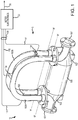
- FIG. 1 shows a vibrating meter 5 comprising a flow meter assembly 10 and meter electronics 20.
- the meter electronics 20 is connected to the meter assembly 10 via leads 100 and is configured to provide measurements of one or more of a density, mass flow rate, volume flow rate, totalized mass flow, temperature, velocity of sound, viscosity, phase composition, and other information over a communication path 26.
- the present invention can be used in any type of Coriolis flow meter regardless of the number of drivers, pick-off sensors, flow conduits, or the operating mode of vibration.
- the flow meter 5 may alternatively comprise a vibratory flow meter that lacks the mass flow measurement capabilities of a Coriolis flow meter, such as a vibratory densitometer.
- the flow meter assembly 10 includes a pair of flanges 101 and 101', manifolds 102, 102', vibratory sensors including a driver 104 and pick-off sensors 105, 105', and flow conduits 103A and 103B.
- the driver 104 and pick-off sensors 105 and 105' are connected to the flow conduits 103A and 103B.
- the flanges 101 and 101' are affixed to the manifolds 102 and 102'.
- the manifolds 102 and 102' can be affixed to opposite ends of a spacer 106.
- the spacer 106 maintains the spacing between the manifolds 102 and 102' in order to prevent undesired vibrations in the flow conduits 103A and 103B.
- the flow material When the flow meter assembly 10 is inserted into a conduit system (not shown) which carries the flow material being measured, the flow material enters the flow meter assembly 10 through the flange 101, passes through the inlet manifold 102 where the total amount of flow material is directed to enter the flow conduits 103A and 103B, flows through the flow conduits 103A and 103B and back into the outlet manifold 102', where it exits the meter assembly 10 through the flange 101'.
- the flow conduits 103A and 103B are selected and appropriately mounted to the inlet manifold 102 and to the outlet manifold 102' so as to have substantially the same mass distribution, moments of inertia, and elastic modules about the bending axes W-W and W'-W' respectively.
- the flow conduits 103A and 103B extend outwardly from the manifolds 102 and 102' in an essentially parallel fashion.
- the flow conduits 103A and 103B are driven by the driver 104 in opposite directions about the respective bending axes W and W' and at what is termed the first out of phase bending mode of the flow meter 5.
- the driver 104 may comprise one of many well known arrangements, such as a magnet mounted to the flow conduit 103A and an opposing coil mounted to the flow conduit 103B. An alternating current is passed through the opposing coil to cause both conduits to oscillate. A suitable drive signal is applied by the meter electronics 20 to the driver 104 via the lead 110.
- the meter electronics 20 can generate a drive signal at a predetermined frequency.
- the meter electronics 20 can generate a drive signal at varying frequencies, including generating multiple superimposed frequencies.
- the meter electronics 20 receives sensor signals on the leads 111 and 111', respectively.
- the meter electronics 20 produces a drive signal on the lead 110 which causes the driver 104 to oscillate the flow conduits 103A and 103B.
- the meter electronics 20 processes the left and right velocity signals from the pick-off sensors 105 and 105' in order to compute a mass flow rate. In some embodiments, the meter electronics 20 can process signals received from the driver 104 to compute a mass flow rate.
- the communication path 26 provides an input and an output means that allows the meter electronics 20 to interface with an operator or with other electronics systems.
- FIG. 1 is provided merely as an example of the operation of a Coriolis flow meter and is not intended to limit the teaching of the present invention.
- low frequency vibratory flow meters can accurately measure density where the negative effects from the velocity of sound are not excessive. Therefore densities obtained from low frequency vibratory flow meters, as is generally known in the art, can typically be assumed to comprise accurate values.
- high frequency meters are available that accurately measure a frequency of vibration of the meter but are encumbered by additional errors caused by velocity of sound effects on density measurements. These two characteristics are advantageously employed to accurately and reliably determine densities and other flow characteristics.
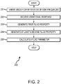
- FIG. 2 shows a flowchart 200 of a method for calculating a fluid parameter of a fluid according to an embodiment of the invention.
- the fluid parameter may comprise, but is not limited to, a velocity of sound, a mass flow rate, or a density.
- the discussion below often refers to the fluid parameter as comprising a velocity of sound. It should be appreciated that this is merely one example and the present invention is not limited to the specific embodiments discussed.
- a flow meter assembly of a vibratory flow meter is vibrated. Only a single vibratory flow meter is needed for this embodiment of the invention.
- the flow meter assembly may be vibrated at one or more frequencies.
- the flow meter assembly is vibrated at a single drive frequency.
- the single drive frequency can generate a vibrational response including the first frequency component and at least a second frequency component, as the vibration of the meter assembly at the single drive frequency can induce multiple frequency response components.
- noise created by flow through the flow meter will generally create vibration in the flow meter assembly at at least a second frequency.
- the at least second frequency will generally be a frequency different than the drive frequency.
- This at least second frequency component of the vibrational response will generally be much smaller in amplitude than the first frequency component.
- the at least second frequency component can be amplified and processed.
- the first vibrational frequency response and the at least second vibrational frequency response can subsequently be processed in the steps below.
- the flow meter assembly of the single flow meter is vibrated at a first drive frequency and is also vibrated at an at least second drive frequency.
- the at least second drive frequency is different than the first drive frequency.
- the first drive frequency comprises a low frequency and the at least second drive frequency comprises a higher drive frequency.
- the single vibratory flow meter may need to be calibrated for both the first drive frequency and the at least second drive frequency.
- the single vibratory flow meter may be calibrated using both air and water, for example.
- the first and second drive frequencies generate a vibrational response comprising a first frequency component and at least a second frequency component. It should be appreciated that the more drive frequencies utilized, the more vibrational responses obtained. Therefore, in some embodiments, more than two drive frequencies are utilized to increase the accuracy of the calculated fluid parameter.
- the flow meter assembly is vibrated at the first drive frequency and then at the at least second drive frequency.
- the flow meter may be simultaneously vibrated at both the first drive frequency and the at least second drive frequency. This can be accomplished if the drive signal comprises a composite of the two or more frequencies, for example.
- a vibrational response of the flow meter includes at least two component frequencies.
- the single vibratory flow meter produces a vibrational response.
- the vibrational response comprises a first frequency component and at least a second frequency component.
- the vibrational response may comprise only a single frequency component. The vibrational response can subsequently be processed in the steps below.
- the vibrational response is received from the single vibratory flow meter.
- the vibrational response may be received from the pick-off sensors 105A, 105B, or alternatively from the driver 104.
- the vibrational response can include the first frequency component and the at least second frequency component.
- the at least second frequency component comprises a different frequency than the first frequency component.
- the at least second frequency component can comprise a higher frequency than the first frequency component.
- the vibrational response can be processed to obtain the first frequency component and the at least second frequency component.
- the processing can comprise separating the vibrational response into the first frequency component and the at least second frequency component.
- the processing can comprise separating the vibrational response into the first frequency component and the at least second frequency component, such as through the use of band-pass filters, for example.
- a first fluid property is generated.
- the first fluid property may comprise a density, a mass flow rate, a volume flow rate, a viscosity, etc. This list is not exhaustive and those skilled in the art will readily recognize additional fluid properties that may be generated. The discussion below refers to the first fluid property as comprising a density measurement solely for the purpose of clarity and should in no way limit the scope of the invention.
- the first density measurement is generated using a first frequency derived from the first frequency component.
- the first density measurement is generated from a stored or a known density value.
- the first density measurement is assumed to comprise the actual density of the flowing material.
- the term "actual" density is meant to mean the density that would be obtained if there were no velocity of sound errors. Therefore, although the term actual density is used, the calculated actual density may still contain errors caused by other variables and therefore could vary from the true density.
- the assumption that the first density measurement comprises the actual density is generally accurate when the first frequency comprises a frequency low enough that the velocity of sound effects that create errors in the density measurements are relatively small and therefore have little, if any, impact. However, in certain applications this may not be a realistic assumption. Therefore, the first density measurement may be compared to an expected density stored or obtained from a lookup table, for example and discarded if the difference between the first density measurement and an expected density measurement exceeds a threshold value.
- the threshold value may be a stored value or may be input from a user/operator. Alternatively, the threshold value may be based on the user/operator's desire for an accurate measurement.
- the expected density may be a stored value or may be input from a user/operator. Alternatively, the expected density may be based on previous measurements.
- the first density measurement may be generated from the stored or known value. In other words, the first density measurement does not need to be generated from the first frequency component.
- the at least second fluid property may comprise a density, a mass flow rate, a volume flow rate, a viscosity, etc. This list is not exhaustive and those skilled in the art will readily recognize additional fluid properties that may be generated.
- the at least second fluid property may comprise the same fluid property as the first fluid property or may comprise a different fluid property.
- the at least second fluid property is described below as comprising a density measurement solely for the purpose of clarity and should in no way limit the scope of the invention.
- the at least second density measurement is generated using an at least second frequency of the at least second frequency component. As discussed above, according to an embodiment of the invention, the at least second frequency is a different frequency than the first frequency.
- the first density measurement and the at least second density measurement will differ. This may be true for example, when the first density measurement comprises the actual density and the second density measurement is obtained at a higher frequency where the density measurement contains errors due to velocity of sound effects.
- the fluid parameter may comprise, for example, a velocity of sound, a density, or a mass flow rate. It should be appreciated that the models provided below are merely examples and those skilled in the art will readily recognize various additional models that are capable of measuring additional fluid parameters.
- various fluid parameters may be determined.
- the specific number of fluid parameters determined may depend, for example, on the number of vibrational frequencies utilized. In the matrix provided, each frequency that the flow meter is vibrated at can provide another equation.
- other fluid parameters may be determined simply by vibrating the flow meter at more frequencies or using other mathematical models. For example, in some embodiments, such as when the fluid comprises a gas, the density measurements may not provide adequate resolution. However, mass flow measurements may provide adequate resolution. Therefore, rather than utilizing a density measurement, a mass flow measurement may be utilized based on equation (2).
- the fluid parameter of the flowing material is determined based on the first density measurement and the at least second density measurement.
- the fluid parameter can comprise a velocity of sound, for example.
- the discussion below often refers to the fluid parameter as comprising the velocity of sound solely as an example. Therefore, the present invention should not be limited to velocity of sound calculations.
- equation (5) can be used on its own to solve for the velocity of sound of the flowing material.
- the first density measurement is generated based on a known or stored density measurement. Therefore, the first density measurement does not need to be generated based on the first frequency component of the vibrational response.
- the first density measurement may be input by a user/operator or retrieved from a memory or the like. Everything in equation (5) except for the velocity of sound can be measured using the first frequency component and the at least second frequency component as discussed above.
- the velocity of sound for the flowing material can be calculated based on the first density measurement, obtained from the first frequency, and the at least second density measurement, obtained from the at least second frequency.
- a calculation of the velocity of sound can be generated using a single vibratory flow meter without requiring external measuring devices as in the prior art.
- more than one flow meter may be used as discussed below.
- equation (5) can be used whenever desired, it provides the most accurate calculation when the difference between the first density measurement and the actual density of the fluid is within a threshold value. As discussed above, this is a reasonable assumption if the velocity of sound effects does not create a substantial error in the density obtained at the first frequency.
- equation (5) is merely one example model equation and other models are contemplated and are within the scope of the invention. Therefore, other fluid parameters may be calculated.
- the first density measurement comprises the actual fluid density. Therefore, according to an embodiment of the invention, if the difference between the first density measurement and the actual density exceeds a threshold value, two equations can be used to solve for a fluid parameter.
- the fluid parameter may comprise the actual fluid density.
- the fluid parameter may comprise the velocity of sound.
- the fluid parameter may comprise the actual mass flow rate. It should be understood that the term "actual" mass flow rate is meant to mean the mass flow rate that would be obtained without velocity of sound effects.
- equations (6) and (7) may be used in combination when the first density measurement is not believed to be the actual density or in situations where the actual density is unknown. This may be determined for example if the difference between the first density measurement and the expected density measurement exceeds a threshold difference, for example. This may also be true if the vibrating meter is considered to be a high frequency meter where the velocity of sound effect on the density readings produces excessive errors even at the first frequency.
- the calculated velocity of sound can be used to compensate for velocity of sound effects in higher frequency meters.
- this calculated velocity of sound can be utilized in higher frequency meters to compensate for density or mass flow rate errors due to the velocity of sound effects using equations (1) and (2), for example.
- either the actual fluid density may need to be known or both equations (6) and (7) may need to be utilized.
- This provides two equations for two unknowns (velocity of sound for the fluid and the actual density measurement). Therefore, the velocity of sound effects in a high frequency meter may now be compensated using the method according to the present invention.
- the present invention is not limited to equations (6) and (7), but rather, persons skilled in the art will readily recognize other similar equations that may be used to calculate other fluid parameters using a first density measurement and at least a second density measurement.
- the calculated velocity of sound may be utilized for a variety of purposes. According to one embodiment of the invention, the calculated velocity of sound may be utilized in conjunction with equations (1) and (2), for example to calculate an error in future density and mass flow measurements. This is especially useful in embodiments where the flow meter is operated at a drive frequency high enough to cause errors in the density and mass flow rate measurements due to velocity of sound effects.
- the present invention has been described in conjunction with a vibratory meter. Although the discussion above has been primarily directed towards a Coriolis flow meter, it should be understood that in many embodiments, the invention can be utilized with other vibratory meters that do not include the capabilities of a Coriolis flow meter.
- the vibratory meter may comprise a vibrating densitometer, for example.
- mass and/or volume flow rates may be desired. Therefore, there may be situations where a Coriolis mass flow meter is implemented but the mass flow rate capabilities are only used on occasion.
- the present invention can calculate a mass flow rate as well. This is especially accurate for compressible fluids, such as gases.
- the present invention can be utilized for a number of purposes once the velocity of sound for the fluid has been determined.
- two variables that are often difficult to determine are the specific heat ratio of the gas, k, and the individual gas constant of the components, R.
- the temperature is a known variable. Therefore, once the velocity of sound is determined, the remaining variables can be easily calculated.
- These two equations can often be used separately or in combination once the velocity of sound is known to determine any number of properties of the system, such as for example the mixture molecular weight, the efficiency of a compressor, measurement correction, etc.
- the particular examples should not in any way limit the scope of the invention, but are provided solely to aid in the understanding of the utility of the present invention and provide examples of how the calculated velocity of sound may be utilized.
- the velocity of sound of the fluid in the vibratory meter can be monitored for changes.
- a change in the velocity of sound for the fluid may be indicative of a number of conditions.
- a calculated velocity of sound for the fluid may be compared to a previously calculated velocity of sound. The comparison may be used as a diagnostic for determining a change in fluid composition, for example. In other embodiments, the comparison may be used to determine a change in fluid phase, for example.
- a change in fluid phase for example, entrained gas in a fluid
- the amount of entrained gas may need to be above a certain threshold amount.
- the particular threshold value may depend on the conditions and fluids monitored.
- the present applicant has determined that a much lower level of entrained gas can be detected by monitoring changes in the velocity of sound for the fluid.
- the velocity of sound for a liquid is greater than the velocity of sound for a gas of the same composition.
- the velocity of sound of a mixed phase is generally lower than either of the pure phases.
- the velocity of sound drops dramatically when the fluid comprises one phase with small amounts of an entrained second phase, for example a liquid with small amounts of entrained gas, or alternatively, a liquid or gas with entrained solids, or a gas with entrained liquid droplets.
- the velocity of sound for the fluid can be determined according to one of the methods outlined in the present application and compared to an expected velocity of sound.
- a user/operator may determine an error.
- the error may comprise determining that the fluid composition and/or fluid phase has changed, for example.
- the expected velocity of sound may be based on a previously calculated velocity of sound or it may be obtained from a lookup table, a value stored in a memory, a user/operator input, etc.
- the comparison as described above compares a first calculated velocity of sound to at least a second velocity of sound
- the comparison may be made between a calculated velocity of sound for the fluid and an expected velocity of sound. Therefore, only one calculation needs to be made in order to perform the diagnostic discussed above.
- A is the flow tube area. Because the density is also known, the mass flow rate can also be calculated as is generally known in the art.
- the present invention allows a mass and/or volume flow rate to be calculated using a vibrating densitometer based on a calculated velocity of sound of the fluid.
- the present invention requires generating first and at least second density measurements.
- the first and at least second density measurements can be based on first and at least a second frequency response.
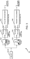
- FIG. 3 shows circuitry 300 for generating a first frequency and at least a second frequency according to an embodiment of the invention.
- This embodiment is used with a single vibratory flow meter and therefore, the circuitry 300 is coupled to a single pick-off 105, 105' of the vibratory flow meter 5.
- the circuitry 300 can comprise a portion of the meter electronics 20. Alternatively, the circuitry 300 can comprise a portion of a processing system 707 (see FIG. 7 and accompanying discussion).
- the circuitry 300 includes filters 302A and 302B, Hilbert transforms 304A and 304B, and analysis blocks 306A and 306B.
- the filter 302A filters out the first frequency component (i.e., a "low mode" in some embodiments) from the pick-off sensors 105, 105' while the filter 302B filters out the at least second frequency component (i.e., a high frequency mode in some embodiments).
- the filters 302A and 302B therefore create two separate processing branches. More than two processing branches can be configured if desired, such as if more than two vibrational frequencies are employed.
- the filtering can comprise band-pass filtering centered around the expected fundamental frequency of the flow meter.
- the filtering can include filtering to remove noise and unwanted signals.
- other conditioning operations can be performed, such as amplification, buffering, etc. If the sensor signals comprise analog signals, this block can further comprise any manner of sampling, digitization, and decimation that are performed in order to produce digital sensor signals.
- the mode filters 302A and 302B comprise digital Finite Impulse Response (FIR) polyphase decimation filters.
- FIR Finite Impulse Response
- the filters can be implemented in a processing device or processing routine of the meter electronics 20 or the processing system 707. These filters provide an optimal method for filtering and decimating the pick-off sensor signal, with the filtering and decimating being performed at the same chronological time and at the same decimation rate.
- the filters 302A and 302B can comprise Infinite Impulse Response (IIR) filters or other suitable digital filters or filter processes.
- IIR Infinite Impulse Response
- the Hilbert transform 304A phase shifts the first frequency component by about ninety degrees and the Hilbert transform 304B phase shifts the at least second frequency component by about ninety degrees.
- the phase shifting operation generates I and Q components (i.e., in-phase and quadrature components) of the respective frequency components.
- I and Q components i.e., in-phase and quadrature components
- the 90 degree phase shift can be performed by any manner of phase shift mechanism or operation.
- the I and Q components are received and processed by the analysis blocks 306A and 306B.
- the processing produces the first frequency f A and at least a second frequency f B .
- the first frequency f A and the at least second frequency f B can be used to generate the first density and the at least second density.
- the frequency according to an embodiment of the invention is advantageously computed from the 90 degree phase shift.
- the frequency in one embodiment uses the 90 degree phase shift and the corresponding sensor signal from which the 90 degree phase shift is derived ( i.e., from the I and Q components).
- the frequency thus derived is obtained without the need for any independent frequency reference signal.
- the frequency is obtained from the single 90 degree phase shift in an operation that is very fast.
- the resulting frequency has a high degree of accuracy.
- FIG. 4 shows details of a portion of the Hilbert transform blocks 304A and 304B according to an embodiment of the invention.
- the Hilbert transform blocks 304A and 304B each include a delay block 411 in parallel with a filter block 412.
- the delay block 411 introduces sampling delays.
- the delay block 411 therefore selects digital signal samples that are chronologically later in time than the digital signal samples that are filtered in parallel by the filter block 412.
- the filter block 412 performs a 90 degree phase shift on the inputted digital signal sample.
- the Hilbert transform blocks 304A and 304B produced 90 degree phase-shifted versions of the pick-off signals, i.e., they produce a quadrature (Q) component of the original, in-phase (I) signal.
- the output of the Hilbert transform blocks 304A and 304B therefore provides the new quadrature (Q) components PO Q and PO Q for the first and the at least second vibrational responses, along with the original, in-phase (I) signal components for the first and the at least second vibrational responses.
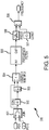
- FIG. 5 is a block diagram of the analysis block 306A or 306B according to an embodiment of the invention.
- the analysis block 306A or 306B receives a signal from a single pick-off (PO) signal.
- PO pick-off
- the analysis block 306A or 306B in the embodiment shown includes a join block 501, a complex conjugate block 502, a sampling block 503, a complex multiplication block 504, a filter block 505, a phase angle block 506, a constant block 507, and a division block 508.
- the join block 501 receives both the in-phase (I) and quadrature (Q) components of a particular vibrational response and passes them on.
- the conjugate block 502 performs a complex conjugate on the vibrational response and forms a negative of the imaginary signal.
- the delay block 503 introduces a sampling delay into the analysis block 306A or 306B and therefore selects a digital signal sample that is chronologically older in time. This older digital signal sample is multiplied with the current digital signal in the complex multiplication block 504.
- the complex multiplication block 504 multiplies the PO signal and the PO conjugate signal, implementing equation (20) below.
- the filter block 505 implements a digital filter, such as the FIR filter previously discussed.
- the filter block 505 can comprise a polyphase decimation filter that is used to remove harmonic content from the in-phase (I) quadrature (Q) components of the sensor signal, as well as to decimate the signal.
- the filter coefficients can be chosen to provide decimation of the inputted signal, such as decimation by a factor of 10, for example.
- the phase angle block 506 determines a phase angle from the in-phase (I) and quadrature (Q) components of the PO signal.
- the phase angle block 506 implements a portion of equation (16) below.
- the constant block 507 supplies a factor comprising a sample rate F s divided by two pi, as shown in equation 18.
- the division block 508 performs the division operation of equation 18.
- ⁇ t ⁇ ⁇ t ⁇ 1 tan ⁇ 1 sin ⁇ t ⁇ ⁇ t ⁇ 1 cos ⁇ t ⁇ ⁇ t ⁇ 1 which is the radian frequency of the vibrational response.
- f PO ⁇ t ⁇ ⁇ t ⁇ 1 ⁇ Fs 2 ⁇ where "Fs" is the rate of the Hilbert transform block 304A or 304B.
- FIG. 6 shows the circuitry 300 for generating a first frequency and at least a second frequency according to an embodiment of the invention. Components in common with other embodiments share reference numbers. This embodiment differs from the previous embodiment 300 by further including an averaging filter 609.
- This embodiment likewise receives a vibrational response from the single pick-off sensor 105, 105'.
- the single vibratory flow meter in this embodiment may be vibrated at only a single frequency, wherein noise in the flow meter generates a second vibrational response, as previously discussed.
- the circuitry 300 therefore takes advantage of noise in the flow system. Since small amounts of flow noise will stimulate sensor modes, a self-induced higher vibrational response mode will be detectable even if no drive signal is provided. This means only one drive signal is required.
- the averaging filter 609 can average out the at least second frequency in order to improve the frequency determination and reduce noise and errors in the result.
- FIG. 7 shows a vibratory flow meter system 700 according to another embodiment of the invention.
- the vibratory flow meter system 700 includes a first flow meter 5A and at least a second flow meter 5B.
- the flow meters 5A and 5B are connected in a conduit 711.
- the flow meters 5A and 5B both measure the flowing material flowing in the conduit 711.
- the processing system 707 is coupled to the first flow meter 5A and the at least second flow meter 5B.
- the processing system 707 receives a first vibrational response from the first flow meter 5A and receives at least a second vibrational response from the at least second flow meter 5B.
- the processing system 707 can determine a first density, at least a second density, and a velocity of sound for the flowing material as previously discussed and as discussed below with FIG. 8 .
- FIG. 8 is a flowchart 800 of a method for determining a fluid parameter of a fluid according to an embodiment of the invention.
- a first vibratory flow meter and at least a second vibratory flow meter are vibrated.
- the first vibratory flow meter is vibrated at a first frequency and generates a first vibrational response.
- the at least second vibratory flow meter is vibrated at an at least second frequency and generates an at least second vibrational response.
- Two or more vibratory flow meters are employed according to this embodiment of the invention. It should be understood that more than two vibratory flow meters can be included and more than two vibrational responses can be received. Multiple vibrational responses can be employed and may further refine the fluid parameter calculations.
- the first vibrational response and the at least second vibrational response are received from the first vibratory flow meter and the at least second vibratory flow meter.
- the at least second vibrational response comprises a different frequency than the first vibrational response, as previously discussed.
- step 803 a first fluid property is generated, as previously discussed.
- step 804 at least a second fluid property is generated, as previously discussed.
- a fluid parameter of the flowing fluid is calculated based on the first fluid property and the at least second fluid property, as previously discussed.
- the above described invention allows a user/operator of a vibratory meter to calculate various fluid parameters.
- the calculation can be performed based on a vibrational response.
- the vibrational response may include at least a first and at least a second frequency component.
- the first and at least second frequency component may be a result of vibrating the flow meter at multiple frequencies.
- the first and at least second frequency component may be a result of vibrating the flow meter at a single frequency. Therefore, the present invention does not require the use of separate acoustic meters to measure the velocity of sound as required in the prior art.
- the present invention can calculate a velocity of sound with only a single flow meter.
- the calculated velocity of sound may be used in a number of different ways as discussed above. It should be appreciated that the implementations discussed above are merely examples to emphasize the utility of the present invention and in no way should it limit the scope of the present invention. Rather, the present invention's applicability is much greater than the limited examples discussed above.
Landscapes
- Physics & Mathematics (AREA)
- General Physics & Mathematics (AREA)
- Fluid Mechanics (AREA)
- Biochemistry (AREA)
- Health & Medical Sciences (AREA)
- Life Sciences & Earth Sciences (AREA)
- Chemical & Material Sciences (AREA)
- Analytical Chemistry (AREA)
- General Health & Medical Sciences (AREA)
- Immunology (AREA)
- Pathology (AREA)
- Signal Processing (AREA)
- Engineering & Computer Science (AREA)
- Measuring Volume Flow (AREA)
Applications Claiming Priority (1)
| Application Number | Priority Date | Filing Date | Title |
|---|---|---|---|
| PCT/US2008/083387 WO2010056244A1 (en) | 2008-11-13 | 2008-11-13 | Method and apparatus for measuring a fluid parameter in a vibrating meter |
Publications (2)
| Publication Number | Publication Date |
|---|---|
| EP2366098A1 EP2366098A1 (en) | 2011-09-21 |
| EP2366098B1 true EP2366098B1 (en) | 2020-12-30 |
Family
ID=40626761
Family Applications (1)
| Application Number | Title | Priority Date | Filing Date |
|---|---|---|---|
| EP08876450.1A Active EP2366098B1 (en) | 2008-11-13 | 2008-11-13 | Method and apparatus for measuring a fluid parameter in a vibrating meter |
Country Status (12)
| Country | Link |
|---|---|
| US (1) | US10466087B2 (enExample) |
| EP (1) | EP2366098B1 (enExample) |
| JP (1) | JP2012508377A (enExample) |
| KR (3) | KR20110079919A (enExample) |
| CN (1) | CN102216739B (enExample) |
| AR (1) | AR074091A1 (enExample) |
| AU (1) | AU2008363999B2 (enExample) |
| BR (1) | BRPI0823229B1 (enExample) |
| CA (1) | CA2743507C (enExample) |
| MX (1) | MX2011004353A (enExample) |
| RU (1) | RU2502962C2 (enExample) |
| WO (1) | WO2010056244A1 (enExample) |
Families Citing this family (27)
| Publication number | Priority date | Publication date | Assignee | Title |
|---|---|---|---|---|
| FR2974902B1 (fr) * | 2011-05-04 | 2014-08-22 | Univ Orleans | Procede de mesure de la viscosite d'un fluide et viscosimetre |
| EP2629066A1 (en) * | 2012-02-18 | 2013-08-21 | ABB Technology AG | Coriolis mass flow meter and signal processing method for a Coriolis mass flow meter |
| AU2012373249C1 (en) * | 2012-03-13 | 2015-07-23 | Micro Motion, Inc. | Indirect mass flow sensor |
| EP2922838B1 (en) * | 2012-10-22 | 2018-03-14 | Concert Pharmaceuticals Inc. | Solid forms of {s-3-(4-amino-1-oxo-isoindolin-2-yl)(piperidine-3,4,4,5,5-d5)-2,6-dione} . |
| KR20160003038A (ko) * | 2013-04-26 | 2016-01-08 | 마이크로 모우션, 인코포레이티드 | 진동 센서 및 진동 센서의 진동을 변동시키는 방법 |
| KR102035859B1 (ko) * | 2014-05-28 | 2019-10-25 | 주식회사 펨토바이오메드 | 점도 측정 방법 |
| CA2960119C (en) * | 2014-09-04 | 2021-08-24 | Micro Motion, Inc. | Differential flowmeter tool |
| KR101939102B1 (ko) * | 2014-09-18 | 2019-01-17 | 마이크로 모우션, 인코포레이티드 | 디퍼렌셜 밀도를 결정하기 위한 방법 및 장치 |
| CN107636427B (zh) * | 2015-03-04 | 2021-04-02 | 高准公司 | 流量计量器测量置信度确定装置和方法 |
| DE102015112737A1 (de) * | 2015-08-03 | 2017-02-09 | Endress + Hauser Flowtec Ag | Verfahren zum Ermitteln eines physikalischen Parameters eines Gases |
| DE102015122661A1 (de) | 2015-12-23 | 2017-06-29 | Endress + Hauser Flowtec Ag | Verfahren zum Ermitteln eines physikalischen Parameters einer mit Gas beladenen Flüssigkeit |
| US10591334B2 (en) | 2016-02-26 | 2020-03-17 | Micro Motion, Inc. | Limiting a drive signal |
| CN108700904B (zh) | 2016-02-26 | 2020-12-11 | 高准公司 | 限制由两个或更多个仪表组件汲取的电流 |
| US11221247B2 (en) | 2016-02-26 | 2022-01-11 | Micro Motion, Inc. | Communicating with two or more hosts |
| CN108700444A (zh) * | 2016-02-26 | 2018-10-23 | 高准公司 | 用于两个或更多仪表配件的仪表电子器件 |
| RU2693911C1 (ru) | 2016-02-26 | 2019-07-05 | Майкро Моушн, Инк. | Обмен данными с двумя или более подчиненными устройствами |
| KR20200014411A (ko) * | 2017-06-14 | 2020-02-10 | 마이크로 모우션, 인코포레이티드 | 진동 유량계의 노치 필터 |
| RU2661541C1 (ru) * | 2017-08-02 | 2018-07-17 | Общество с ограниченной ответственностью "Метрологический центр Контрольно-измерительные технологии" (ООО "МЦ КИТ") | Способ определения массы жидкой и парогазовой фракций в резервуаре технологического объекта |
| US20200182675A1 (en) * | 2017-08-08 | 2020-06-11 | Micro Motion, Inc. | Flowmeter false totalizing elimination devices and methods |
| US10598531B2 (en) * | 2018-04-23 | 2020-03-24 | General Electric Company | Coriolis flow meter with multiple actuators arranged on a flow tube and driven in different planes |
| US12449290B2 (en) * | 2018-12-26 | 2025-10-21 | Texas Instruments Incorporated | Dynamic temperature calibration of ultrasonic transducers |
| DE102019117101A1 (de) | 2019-06-25 | 2020-12-31 | Endress+Hauser Flowtec Ag | Verfahren zum Ermitteln eines physikalischen Parameters einer beladenen Flüssigkeit |
| EP4051992A1 (en) * | 2019-11-01 | 2022-09-07 | Micro Motion, Inc. | Enhanced supercritical fluid measurement with vibratory sensors |
| CN111119849A (zh) * | 2020-03-06 | 2020-05-08 | 中国石油大学(华东) | 基于多频科氏原理的井口计量装置 |
| KR102840490B1 (ko) * | 2020-07-08 | 2025-07-30 | 마이크로 모우션, 인코포레이티드 | 진동계 q를 계산하기 위한 방법 및 장치 |
| MX2023014091A (es) * | 2021-06-28 | 2023-12-11 | Micro Motion Inc | Medicion de fluidos no ideal por flujometro de coriolis y metodos relacionados. |
| CN114019496B (zh) * | 2022-01-05 | 2022-03-08 | 北京邮电大学 | 一种管道内液体流速非接触测量方法及装置 |
Family Cites Families (14)
| Publication number | Priority date | Publication date | Assignee | Title |
|---|---|---|---|---|
| US4262523A (en) * | 1977-12-09 | 1981-04-21 | The Solartron Electronic Group Limited | Measurement of fluid density |
| US5661232A (en) * | 1996-03-06 | 1997-08-26 | Micro Motion, Inc. | Coriolis viscometer using parallel connected Coriolis mass flowmeters |
| US5734112A (en) | 1996-08-14 | 1998-03-31 | Micro Motion, Inc. | Method and apparatus for measuring pressure in a coriolis mass flowmeter |
| EP1090274B1 (en) | 1998-06-26 | 2017-03-15 | Weatherford Technology Holdings, LLC | Fluid parameter measurement in pipes using acoustic pressures |
| US6412355B1 (en) | 1999-05-20 | 2002-07-02 | Endress + Hauser Flowtec Ag | Coriolis-type flow meter and method for measuring the mass flow rate of a gaseous or vaporous fluid |
| JP3245144B2 (ja) * | 1999-05-20 | 2002-01-07 | エンドレス ウント ハウザー フローテック アクチエンゲゼルシャフト | ガス状又は蒸気状の流体の質量流量を測定する方法 |
| US6502466B1 (en) * | 1999-06-29 | 2003-01-07 | Direct Measurement Corporation | System and method for fluid compressibility compensation in a Coriolis mass flow meter |
| US7032432B2 (en) * | 2002-01-23 | 2006-04-25 | Cidra Corporation | Apparatus and method for measuring parameters of a mixture having liquid droplets suspended in a vapor flowing in a pipe |
| US7299705B2 (en) | 2003-07-15 | 2007-11-27 | Cidra Corporation | Apparatus and method for augmenting a Coriolis meter |
| KR101484074B1 (ko) * | 2005-03-29 | 2015-01-19 | 마이크로 모우션, 인코포레이티드 | 유체의 특성을 결정하기 위한 방법 및 코리올리 유량계 |
| WO2007074055A1 (en) * | 2005-12-27 | 2007-07-05 | Endress+Hauser Flowtec Ag | In-line measuring devices and method for compensating measurement errors in in-line measuring devices |
| DE102007061690A1 (de) | 2006-12-21 | 2008-06-26 | Abb Ag | Verfahren zum Betrieb eines Messgerätes vom Vibrationstyp sowie Messgerät von Vibrationstyp selbst |
| BRPI0721881B1 (pt) * | 2007-07-30 | 2018-12-26 | Micro Motion Inc | medidor de fluxo vibratório, sistema de medidor de fluxo vibratório, e método para medir características de fluxo de um fluxo trifásico |
| MX2010003305A (es) * | 2007-10-08 | 2010-04-21 | Micro Motion Inc | Un dispositivo de flujo y metodo para operar un dispositivo de flujo. |
-
2008
- 2008-11-13 KR KR1020117013553A patent/KR20110079919A/ko not_active Ceased
- 2008-11-13 KR KR1020147017769A patent/KR101609818B1/ko active Active
- 2008-11-13 BR BRPI0823229A patent/BRPI0823229B1/pt active IP Right Grant
- 2008-11-13 US US13/124,192 patent/US10466087B2/en active Active
- 2008-11-13 JP JP2011535550A patent/JP2012508377A/ja active Pending
- 2008-11-13 KR KR1020137011631A patent/KR20130055704A/ko not_active Ceased
- 2008-11-13 MX MX2011004353A patent/MX2011004353A/es active IP Right Grant
- 2008-11-13 WO PCT/US2008/083387 patent/WO2010056244A1/en not_active Ceased
- 2008-11-13 CN CN200880131965.7A patent/CN102216739B/zh active Active
- 2008-11-13 AU AU2008363999A patent/AU2008363999B2/en active Active
- 2008-11-13 RU RU2011123896/28A patent/RU2502962C2/ru active
- 2008-11-13 EP EP08876450.1A patent/EP2366098B1/en active Active
- 2008-11-13 CA CA2743507A patent/CA2743507C/en active Active
-
2009
- 2009-11-06 AR ARP090104298A patent/AR074091A1/es active IP Right Grant
Non-Patent Citations (1)
| Title |
|---|
| None * |
Also Published As
| Publication number | Publication date |
|---|---|
| CA2743507A1 (en) | 2010-05-20 |
| EP2366098A1 (en) | 2011-09-21 |
| WO2010056244A1 (en) | 2010-05-20 |
| RU2011123896A (ru) | 2012-12-20 |
| KR20110079919A (ko) | 2011-07-11 |
| RU2502962C2 (ru) | 2013-12-27 |
| CA2743507C (en) | 2018-05-01 |
| AR074091A1 (es) | 2010-12-22 |
| HK1162660A1 (zh) | 2012-08-31 |
| BRPI0823229B1 (pt) | 2019-01-22 |
| US10466087B2 (en) | 2019-11-05 |
| AU2008363999B2 (en) | 2013-02-07 |
| KR20130055704A (ko) | 2013-05-28 |
| CN102216739A (zh) | 2011-10-12 |
| AU2008363999A1 (en) | 2010-05-20 |
| MX2011004353A (es) | 2011-05-24 |
| US20110264385A1 (en) | 2011-10-27 |
| JP2012508377A (ja) | 2012-04-05 |
| KR101609818B1 (ko) | 2016-04-20 |
| KR20140093743A (ko) | 2014-07-28 |
| BRPI0823229A2 (pt) | 2015-06-16 |
| CN102216739B (zh) | 2016-08-24 |
Similar Documents
| Publication | Publication Date | Title |
|---|---|---|
| EP2366098B1 (en) | Method and apparatus for measuring a fluid parameter in a vibrating meter | |
| EP2179254B1 (en) | Flow meter system and method for measuring flow characteristics of a three phase flow | |
| AU2006304333B2 (en) | Meter electronics and methods for determining a phase difference between a first sensor signal and a second sensor signal of a flow meter | |
| AU2006251657A1 (en) | Meter electronics and methods for rapidly determining a mass fraction of a multi-phase from a coriolis flow meter signal | |
| CA2608843C (en) | Meter electronics and methods for determining void fraction of gas | |
| JP6080880B2 (ja) | 振動計にて流体パラメータを測定する方法及び装置 | |
| HK1162660B (en) | Method and apparatus for measuring a fluid parameter in a vibrating meter | |
| HK1145707B (en) | Flow meter system and method for measuring flow characteristics of a three phase flow | |
| HK1124113B (en) | Meter electronics and methods for rapidly determining a mass fraction of a multi-phase from a coriolis flow meter signal |
Legal Events
| Date | Code | Title | Description |
|---|---|---|---|
| PUAI | Public reference made under article 153(3) epc to a published international application that has entered the european phase |
Free format text: ORIGINAL CODE: 0009012 |
|
| 17P | Request for examination filed |
Effective date: 20110612 |
|
| AK | Designated contracting states |
Kind code of ref document: A1 Designated state(s): AT BE BG CH CY CZ DE DK EE ES FI FR GB GR HR HU IE IS IT LI LT LU LV MC MT NL NO PL PT RO SE SI SK TR |
|
| DAX | Request for extension of the european patent (deleted) | ||
| STAA | Information on the status of an ep patent application or granted ep patent |
Free format text: STATUS: EXAMINATION IS IN PROGRESS |
|
| 17Q | First examination report despatched |
Effective date: 20170330 |
|
| GRAP | Despatch of communication of intention to grant a patent |
Free format text: ORIGINAL CODE: EPIDOSNIGR1 |
|
| STAA | Information on the status of an ep patent application or granted ep patent |
Free format text: STATUS: GRANT OF PATENT IS INTENDED |
|
| INTG | Intention to grant announced |
Effective date: 20200318 |
|
| GRAJ | Information related to disapproval of communication of intention to grant by the applicant or resumption of examination proceedings by the epo deleted |
Free format text: ORIGINAL CODE: EPIDOSDIGR1 |
|
| STAA | Information on the status of an ep patent application or granted ep patent |
Free format text: STATUS: EXAMINATION IS IN PROGRESS |
|
| GRAP | Despatch of communication of intention to grant a patent |
Free format text: ORIGINAL CODE: EPIDOSNIGR1 |
|
| STAA | Information on the status of an ep patent application or granted ep patent |
Free format text: STATUS: GRANT OF PATENT IS INTENDED |
|
| INTC | Intention to grant announced (deleted) | ||
| GRAS | Grant fee paid |
Free format text: ORIGINAL CODE: EPIDOSNIGR3 |
|
| INTG | Intention to grant announced |
Effective date: 20201021 |
|
| GRAA | (expected) grant |
Free format text: ORIGINAL CODE: 0009210 |
|
| STAA | Information on the status of an ep patent application or granted ep patent |
Free format text: STATUS: THE PATENT HAS BEEN GRANTED |
|
| AK | Designated contracting states |
Kind code of ref document: B1 Designated state(s): AT BE BG CH CY CZ DE DK EE ES FI FR GB GR HR HU IE IS IT LI LT LU LV MC MT NL NO PL PT RO SE SI SK TR |
|
| REG | Reference to a national code |
Ref country code: GB Ref legal event code: FG4D |
|
| REG | Reference to a national code |
Ref country code: AT Ref legal event code: REF Ref document number: 1350380 Country of ref document: AT Kind code of ref document: T Effective date: 20210115 |
|
| REG | Reference to a national code |
Ref country code: DE Ref legal event code: R096 Ref document number: 602008063622 Country of ref document: DE |
|
| REG | Reference to a national code |
Ref country code: IE Ref legal event code: FG4D |
|
| REG | Reference to a national code |
Ref country code: CH Ref legal event code: NV Representative=s name: VOSSIUS AND PARTNER PATENTANWAELTE RECHTSANWAE, CH |
|
| REG | Reference to a national code |
Ref country code: NL Ref legal event code: FP |
|
| PG25 | Lapsed in a contracting state [announced via postgrant information from national office to epo] |
Ref country code: NO Free format text: LAPSE BECAUSE OF FAILURE TO SUBMIT A TRANSLATION OF THE DESCRIPTION OR TO PAY THE FEE WITHIN THE PRESCRIBED TIME-LIMIT Effective date: 20210330 Ref country code: FI Free format text: LAPSE BECAUSE OF FAILURE TO SUBMIT A TRANSLATION OF THE DESCRIPTION OR TO PAY THE FEE WITHIN THE PRESCRIBED TIME-LIMIT Effective date: 20201230 Ref country code: GR Free format text: LAPSE BECAUSE OF FAILURE TO SUBMIT A TRANSLATION OF THE DESCRIPTION OR TO PAY THE FEE WITHIN THE PRESCRIBED TIME-LIMIT Effective date: 20210331 |
|
| REG | Reference to a national code |
Ref country code: AT Ref legal event code: MK05 Ref document number: 1350380 Country of ref document: AT Kind code of ref document: T Effective date: 20201230 |
|
| PG25 | Lapsed in a contracting state [announced via postgrant information from national office to epo] |
Ref country code: BG Free format text: LAPSE BECAUSE OF FAILURE TO SUBMIT A TRANSLATION OF THE DESCRIPTION OR TO PAY THE FEE WITHIN THE PRESCRIBED TIME-LIMIT Effective date: 20210330 Ref country code: LV Free format text: LAPSE BECAUSE OF FAILURE TO SUBMIT A TRANSLATION OF THE DESCRIPTION OR TO PAY THE FEE WITHIN THE PRESCRIBED TIME-LIMIT Effective date: 20201230 Ref country code: SE Free format text: LAPSE BECAUSE OF FAILURE TO SUBMIT A TRANSLATION OF THE DESCRIPTION OR TO PAY THE FEE WITHIN THE PRESCRIBED TIME-LIMIT Effective date: 20201230 |
|
| PG25 | Lapsed in a contracting state [announced via postgrant information from national office to epo] |
Ref country code: HR Free format text: LAPSE BECAUSE OF FAILURE TO SUBMIT A TRANSLATION OF THE DESCRIPTION OR TO PAY THE FEE WITHIN THE PRESCRIBED TIME-LIMIT Effective date: 20201230 |
|
| REG | Reference to a national code |
Ref country code: LT Ref legal event code: MG9D |
|
| PG25 | Lapsed in a contracting state [announced via postgrant information from national office to epo] |
Ref country code: LT Free format text: LAPSE BECAUSE OF FAILURE TO SUBMIT A TRANSLATION OF THE DESCRIPTION OR TO PAY THE FEE WITHIN THE PRESCRIBED TIME-LIMIT Effective date: 20201230 Ref country code: RO Free format text: LAPSE BECAUSE OF FAILURE TO SUBMIT A TRANSLATION OF THE DESCRIPTION OR TO PAY THE FEE WITHIN THE PRESCRIBED TIME-LIMIT Effective date: 20201230 Ref country code: PT Free format text: LAPSE BECAUSE OF FAILURE TO SUBMIT A TRANSLATION OF THE DESCRIPTION OR TO PAY THE FEE WITHIN THE PRESCRIBED TIME-LIMIT Effective date: 20210430 Ref country code: SK Free format text: LAPSE BECAUSE OF FAILURE TO SUBMIT A TRANSLATION OF THE DESCRIPTION OR TO PAY THE FEE WITHIN THE PRESCRIBED TIME-LIMIT Effective date: 20201230 Ref country code: EE Free format text: LAPSE BECAUSE OF FAILURE TO SUBMIT A TRANSLATION OF THE DESCRIPTION OR TO PAY THE FEE WITHIN THE PRESCRIBED TIME-LIMIT Effective date: 20201230 Ref country code: CZ Free format text: LAPSE BECAUSE OF FAILURE TO SUBMIT A TRANSLATION OF THE DESCRIPTION OR TO PAY THE FEE WITHIN THE PRESCRIBED TIME-LIMIT Effective date: 20201230 |
|
| PG25 | Lapsed in a contracting state [announced via postgrant information from national office to epo] |
Ref country code: PL Free format text: LAPSE BECAUSE OF FAILURE TO SUBMIT A TRANSLATION OF THE DESCRIPTION OR TO PAY THE FEE WITHIN THE PRESCRIBED TIME-LIMIT Effective date: 20201230 Ref country code: AT Free format text: LAPSE BECAUSE OF FAILURE TO SUBMIT A TRANSLATION OF THE DESCRIPTION OR TO PAY THE FEE WITHIN THE PRESCRIBED TIME-LIMIT Effective date: 20201230 |
|
| PG25 | Lapsed in a contracting state [announced via postgrant information from national office to epo] |
Ref country code: IS Free format text: LAPSE BECAUSE OF FAILURE TO SUBMIT A TRANSLATION OF THE DESCRIPTION OR TO PAY THE FEE WITHIN THE PRESCRIBED TIME-LIMIT Effective date: 20210430 |
|
| REG | Reference to a national code |
Ref country code: DE Ref legal event code: R097 Ref document number: 602008063622 Country of ref document: DE |
|
| PLBE | No opposition filed within time limit |
Free format text: ORIGINAL CODE: 0009261 |
|
| STAA | Information on the status of an ep patent application or granted ep patent |
Free format text: STATUS: NO OPPOSITION FILED WITHIN TIME LIMIT |
|
| PG25 | Lapsed in a contracting state [announced via postgrant information from national office to epo] |
Ref country code: DK Free format text: LAPSE BECAUSE OF FAILURE TO SUBMIT A TRANSLATION OF THE DESCRIPTION OR TO PAY THE FEE WITHIN THE PRESCRIBED TIME-LIMIT Effective date: 20201230 Ref country code: ES Free format text: LAPSE BECAUSE OF FAILURE TO SUBMIT A TRANSLATION OF THE DESCRIPTION OR TO PAY THE FEE WITHIN THE PRESCRIBED TIME-LIMIT Effective date: 20201230 |
|
| 26N | No opposition filed |
Effective date: 20211001 |
|
| PG25 | Lapsed in a contracting state [announced via postgrant information from national office to epo] |
Ref country code: SI Free format text: LAPSE BECAUSE OF FAILURE TO SUBMIT A TRANSLATION OF THE DESCRIPTION OR TO PAY THE FEE WITHIN THE PRESCRIBED TIME-LIMIT Effective date: 20201230 |
|
| PG25 | Lapsed in a contracting state [announced via postgrant information from national office to epo] |
Ref country code: IS Free format text: LAPSE BECAUSE OF FAILURE TO SUBMIT A TRANSLATION OF THE DESCRIPTION OR TO PAY THE FEE WITHIN THE PRESCRIBED TIME-LIMIT Effective date: 20210430 |
|
| PG25 | Lapsed in a contracting state [announced via postgrant information from national office to epo] |
Ref country code: MC Free format text: LAPSE BECAUSE OF FAILURE TO SUBMIT A TRANSLATION OF THE DESCRIPTION OR TO PAY THE FEE WITHIN THE PRESCRIBED TIME-LIMIT Effective date: 20201230 |
|
| PG25 | Lapsed in a contracting state [announced via postgrant information from national office to epo] |
Ref country code: LU Free format text: LAPSE BECAUSE OF NON-PAYMENT OF DUE FEES Effective date: 20211113 Ref country code: BE Free format text: LAPSE BECAUSE OF NON-PAYMENT OF DUE FEES Effective date: 20211130 |
|
| REG | Reference to a national code |
Ref country code: BE Ref legal event code: MM Effective date: 20211130 |
|
| PG25 | Lapsed in a contracting state [announced via postgrant information from national office to epo] |
Ref country code: IE Free format text: LAPSE BECAUSE OF NON-PAYMENT OF DUE FEES Effective date: 20211113 |
|
| PG25 | Lapsed in a contracting state [announced via postgrant information from national office to epo] |
Ref country code: HU Free format text: LAPSE BECAUSE OF FAILURE TO SUBMIT A TRANSLATION OF THE DESCRIPTION OR TO PAY THE FEE WITHIN THE PRESCRIBED TIME-LIMIT; INVALID AB INITIO Effective date: 20081113 Ref country code: CY Free format text: LAPSE BECAUSE OF FAILURE TO SUBMIT A TRANSLATION OF THE DESCRIPTION OR TO PAY THE FEE WITHIN THE PRESCRIBED TIME-LIMIT Effective date: 20201230 |
|
| P01 | Opt-out of the competence of the unified patent court (upc) registered |
Effective date: 20230524 |
|
| PG25 | Lapsed in a contracting state [announced via postgrant information from national office to epo] |
Ref country code: TR Free format text: LAPSE BECAUSE OF FAILURE TO SUBMIT A TRANSLATION OF THE DESCRIPTION OR TO PAY THE FEE WITHIN THE PRESCRIBED TIME-LIMIT Effective date: 20201230 |
|
| PG25 | Lapsed in a contracting state [announced via postgrant information from national office to epo] |
Ref country code: MT Free format text: LAPSE BECAUSE OF FAILURE TO SUBMIT A TRANSLATION OF THE DESCRIPTION OR TO PAY THE FEE WITHIN THE PRESCRIBED TIME-LIMIT Effective date: 20201230 |
|
| PGFP | Annual fee paid to national office [announced via postgrant information from national office to epo] |
Ref country code: NL Payment date: 20251022 Year of fee payment: 18 |
|
| REG | Reference to a national code |
Ref country code: CH Ref legal event code: U11 Free format text: ST27 STATUS EVENT CODE: U-0-0-U10-U11 (AS PROVIDED BY THE NATIONAL OFFICE) Effective date: 20251201 |
|
| PGFP | Annual fee paid to national office [announced via postgrant information from national office to epo] |
Ref country code: DE Payment date: 20251022 Year of fee payment: 18 |
|
| PGFP | Annual fee paid to national office [announced via postgrant information from national office to epo] |
Ref country code: GB Payment date: 20251022 Year of fee payment: 18 |
|
| PGFP | Annual fee paid to national office [announced via postgrant information from national office to epo] |
Ref country code: IT Payment date: 20251022 Year of fee payment: 18 |
|
| PGFP | Annual fee paid to national office [announced via postgrant information from national office to epo] |
Ref country code: FR Payment date: 20251022 Year of fee payment: 18 |
|
| PGFP | Annual fee paid to national office [announced via postgrant information from national office to epo] |
Ref country code: CH Payment date: 20251201 Year of fee payment: 18 |