EP2366079B1 - Plaque lumineuse - Google Patents
Plaque lumineuse Download PDFInfo
- Publication number
- EP2366079B1 EP2366079B1 EP09760941.6A EP09760941A EP2366079B1 EP 2366079 B1 EP2366079 B1 EP 2366079B1 EP 09760941 A EP09760941 A EP 09760941A EP 2366079 B1 EP2366079 B1 EP 2366079B1
- Authority
- EP
- European Patent Office
- Prior art keywords
- rigid support
- edge
- optical fibers
- complex according
- fabric
- Prior art date
- Legal status (The legal status is an assumption and is not a legal conclusion. Google has not performed a legal analysis and makes no representation as to the accuracy of the status listed.)
- Not-in-force
Links
Images

Classifications
-
- G—PHYSICS
- G09—EDUCATION; CRYPTOGRAPHY; DISPLAY; ADVERTISING; SEALS
- G09F—DISPLAYING; ADVERTISING; SIGNS; LABELS OR NAME-PLATES; SEALS
- G09F19/00—Advertising or display means not otherwise provided for
- G09F19/22—Advertising or display means on roads, walls or similar surfaces, e.g. illuminated
-
- D—TEXTILES; PAPER
- D03—WEAVING
- D03D—WOVEN FABRICS; METHODS OF WEAVING; LOOMS
- D03D15/00—Woven fabrics characterised by the material, structure or properties of the fibres, filaments, yarns, threads or other warp or weft elements used
- D03D15/50—Woven fabrics characterised by the material, structure or properties of the fibres, filaments, yarns, threads or other warp or weft elements used characterised by the properties of the yarns or threads
- D03D15/547—Woven fabrics characterised by the material, structure or properties of the fibres, filaments, yarns, threads or other warp or weft elements used characterised by the properties of the yarns or threads with optical functions other than colour, e.g. comprising light-emitting fibres
-
- E—FIXED CONSTRUCTIONS
- E04—BUILDING
- E04B—GENERAL BUILDING CONSTRUCTIONS; WALLS, e.g. PARTITIONS; ROOFS; FLOORS; CEILINGS; INSULATION OR OTHER PROTECTION OF BUILDINGS
- E04B2/00—Walls, e.g. partitions, for buildings; Wall construction with regard to insulation; Connections specially adapted to walls
- E04B2/74—Removable non-load-bearing partitions; Partitions with a free upper edge
- E04B2/7407—Removable non-load-bearing partitions; Partitions with a free upper edge assembled using frames with infill panels or coverings only; made-up of panels and a support structure incorporating posts
- E04B2/7416—Removable non-load-bearing partitions; Partitions with a free upper edge assembled using frames with infill panels or coverings only; made-up of panels and a support structure incorporating posts with free upper edge, e.g. for use as office space dividers
-
- G—PHYSICS
- G02—OPTICS
- G02B—OPTICAL ELEMENTS, SYSTEMS OR APPARATUS
- G02B6/00—Light guides; Structural details of arrangements comprising light guides and other optical elements, e.g. couplings
- G02B6/0001—Light guides; Structural details of arrangements comprising light guides and other optical elements, e.g. couplings specially adapted for lighting devices or systems
- G02B6/0005—Light guides; Structural details of arrangements comprising light guides and other optical elements, e.g. couplings specially adapted for lighting devices or systems the light guides being of the fibre type
- G02B6/001—Light guides; Structural details of arrangements comprising light guides and other optical elements, e.g. couplings specially adapted for lighting devices or systems the light guides being of the fibre type the light being emitted along at least a portion of the lateral surface of the fibre
-
- G—PHYSICS
- G09—EDUCATION; CRYPTOGRAPHY; DISPLAY; ADVERTISING; SEALS
- G09F—DISPLAYING; ADVERTISING; SIGNS; LABELS OR NAME-PLATES; SEALS
- G09F13/00—Illuminated signs; Luminous advertising
- G09F13/04—Signs, boards or panels, illuminated from behind the insignia
- G09F13/14—Arrangements of reflectors therein
-
- D—TEXTILES; PAPER
- D10—INDEXING SCHEME ASSOCIATED WITH SUBLASSES OF SECTION D, RELATING TO TEXTILES
- D10B—INDEXING SCHEME ASSOCIATED WITH SUBLASSES OF SECTION D, RELATING TO TEXTILES
- D10B2401/00—Physical properties
- D10B2401/20—Physical properties optical
-
- D—TEXTILES; PAPER
- D10—INDEXING SCHEME ASSOCIATED WITH SUBLASSES OF SECTION D, RELATING TO TEXTILES
- D10B—INDEXING SCHEME ASSOCIATED WITH SUBLASSES OF SECTION D, RELATING TO TEXTILES
- D10B2503/00—Domestic or personal
- D10B2503/04—Floor or wall coverings; Carpets
-
- E—FIXED CONSTRUCTIONS
- E04—BUILDING
- E04B—GENERAL BUILDING CONSTRUCTIONS; WALLS, e.g. PARTITIONS; ROOFS; FLOORS; CEILINGS; INSULATION OR OTHER PROTECTION OF BUILDINGS
- E04B2/00—Walls, e.g. partitions, for buildings; Wall construction with regard to insulation; Connections specially adapted to walls
- E04B2/74—Removable non-load-bearing partitions; Partitions with a free upper edge
- E04B2002/749—Partitions with screw-type jacks
-
- F—MECHANICAL ENGINEERING; LIGHTING; HEATING; WEAPONS; BLASTING
- F21—LIGHTING
- F21V—FUNCTIONAL FEATURES OR DETAILS OF LIGHTING DEVICES OR SYSTEMS THEREOF; STRUCTURAL COMBINATIONS OF LIGHTING DEVICES WITH OTHER ARTICLES, NOT OTHERWISE PROVIDED FOR
- F21V2200/00—Use of light guides, e.g. fibre optic devices, in lighting devices or systems
- F21V2200/10—Use of light guides, e.g. fibre optic devices, in lighting devices or systems of light guides of the optical fibres type
- F21V2200/15—Use of light guides, e.g. fibre optic devices, in lighting devices or systems of light guides of the optical fibres type the light being emitted along at least a portion of the outer surface of the guide
Definitions
- the present invention relates to a light plate. It relates more particularly to a rigid support, such as a facing plate, provided with lighting means that can be used to produce a vertical wall -in the case for example of a partition- or a horizontal wall -for example to a ceiling-.
- luminous fabric it is known to produce a fabric, called luminous fabric, to achieve an extended light source and distributed over an entire surface, unlike usual light sources which are either point (incandescent lamp, halogen lamp, LED, ...) or linear (neon tube, halogen lamp, ).
- a luminous fabric and its weaving method are disclosed in the document FR-2,859,737 .
- the technical problem at the origin of the present invention is to provide means for producing a wall incorporating at least one rigid support associated with a light fabric. It is a question of integrating a rigid support covered with a luminous fabric in a horizontal or vertical wall with the stresses existing in the field of the building.
- the present invention proposes, as in the document US2006 / 0087864 a complex comprising a rigid support coated with a luminous fabric, wherein the rigid support has a front face, a rear face opposite to the front face, a first edge and a second edge opposite the first, the light fabric covering at least partially the front face of the rigid support extending from the first edge to the second edge.
- the light fabric comprises optical fibers extending on the front face of the rigid support substantially perpendicular to the first edge and the second edge.
- the invention thus provides means for tensioning the light fabric on the rigid support.
- the clamping means used advantageously also protect the folded ends of the optical fibers.
- An advantageous variant of the invention provides that second ends of the optical fibers are folded around the second edge towards the rear face of the rigid support, and that clamping means are provided at the second edge and form a clamp which grips the parts. folded optical fibers and the second edge of the rigid support.
- the first and possibly also the second ends of the optical fibers are connected to a housing fixed on the rear face of the rigid support and inside which there are light sources.
- the clamping means comprise for example a base connecting two substantially parallel elastic arms.
- An alternative embodiment provides that the base and the two resilient arms form a profiled piece in one piece while another variant proposes that the distance between the two elastic arms is adjustable, and that corresponding adjustment means are integrated in the base.
- the luminous fabric is advantageously covered with a layer of a translucent material.
- the fabric is invisible until the corresponding light sources are turned on and becomes visible only when the light sources make the illuminating fabric illuminate.
- the invention advantageously provides that the clamping means also enclose the layer of translucent material.
- the rigid support is for example a plasterboard.
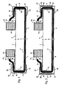
- the figure 1 is a side view of a light plate according to the present invention.
- This plate comprises a rigid support 2, a luminous fabric 4 and its accessories as well as means for mounting the luminous fabric 4 on the rigid support 2.
- the rigid support 2 is for example a facing plate of the type used for the production of walls, both horizontal walls - ceilings - vertical walls -cloisons-. This is for example a plasterboard such plates known as BA13 when it is a partition.
- This rigid support 2 has two large faces and four edges.
- a large face is called the front face 6, the other large face, opposite the front face 6, is called the rear face 8.
- the following description will mainly refer to a first edge 10 and a second edge 12 opposite the first edge 10.
- the light fabric 4 covers-at least partially-the front face 6 of the rigid support 2.
- the weft threads of the light fabric 4 are optical fibers 14. The latter protrude from the surface of the light fabric 4 so that each can be connected to a light source (not shown).
- the optical fibers could be warp threads of the light fabric.
- first ends of the optical fibers 14 are folded at 180 ° around the first edge 10 towards the rear face 8 of the rigid support 2 and are connected to light sources which are at the rear of the rigid support 2.
- the light sources are arranged in a defined housing inside a first housing 16. These are for example light-emitting diodes, also known as LEDs.
- the optical fibers 14 are connected by nut connectors 18 of a type known to those skilled in the art, to a plate, called lower plate 20, of the first housing 16.
- second ends of the optical fibers 14 are folded at 180 ° around the second edge 12 towards the rear face 8 of the rigid support 2 and are connected to light sources (not shown) such as LEDs arranged in a housing defined in FIG. The interior of a second housing 22.
- the optical fibers 14 are connected by nut connectors 18 to a plate, called the upper plate 24, of the housing 20.
- the first housing 16 is for example made using a profile and possibly a cover. It has, in a preferred embodiment shown in the drawings, an elongated parallelepipedal shape and extends parallel to the first edge 10 (and the second edge 12) of the rigid support 2.
- the second housing 22 is similar to the first housing 16.
- the first housing 16, as well as the second housing 22, are fixed on the rear face 8 of the rigid support 2
- This attachment can be made by any means and depends in particular on the material in which the rigid support is made. In the case of a rigid support formed by a plasterboard, it is possible, for example, to come and glue the housings onto the rear face 8 of the rigid support 2.
- the luminous fabric 4 is stretched on the front face 6 of the rigid support 2 and is held taut on this front face 6 by two clamps 26.
- Each clip 26 is in this first embodiment as an integral profiled piece having a U-shaped cross-section.
- a clip 26 has a base 28 and two legs 30.
- the base 28 is for example flat and extends facing the first edge 10 or the second edge 12 of the rigid support 2 over substantially the entire length of the corresponding edge.
- the branches 30 are connected to the base 28 so as to be able to move away from one another elastically.
- the free ends of the branches 30 are slightly folded towards the opposite branch 30 thus forming a clamp.
- the clamp 26 is configured so that when it is at rest the distance between the slightly folded free ends of the branches 30 is less than the thickness of the rigid support 2 increased by the thickness of the light fabric 4 and the optical fibers 14.
- a clamp 26 it is appropriate to spread its branches 30 which then pinch the light fabric 4 on the rigid support 2.
- the clip 26 comes to grip the corresponding edge of the rigid support 2 by tightening the fabric 4, on the rigid support 2.
- the clamp 26 also protects the 180 ° folded portion of the optical fibers 14.
- the figure 2 shows an alternative embodiment of a rigid support complex / light fabric according to the present invention.
- This complex has the same structure as that of the figure 1 .
- the clip 26 in one piece of the figure 1 is here replaced by a clip 26 'in two parts.
- the clamp 26 takes up the structure of the clamp 26 with a base and two branches 30'.
- Each of the branches 30 ' is intended to bear against one face of the rigid support 2 by pressing against this face the light fabric 4 or the optical fibers 14.
- a first leg 30 ' is provided with a male piece 32 while the other leg 30' is provided with a female part 34 in which the male piece 32 can slide.
- Snap-fastening means are for example provided to hold the male piece 32 in a given position ensuring a good tightening of the light fabric 4 on the front face 6 of the rigid support 2 with respect to the female piece 34.
- a complex formed of a rigid support 2 and a luminous fabric 4 and shown on the Figures 1 and 2 can be implemented as shown to achieve a ceiling.
- Such a complex can indeed come to rest on a structure made under a floor to receive siding, also called ceiling tiles. It suffices here to adapt the size of the rigid support 2 taking into account the clamps 26 or 26 'to the dimensions of the structure.
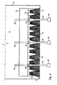
- the figure 3 shows how a complex shown on the figure 1 can also be adapted for the production of a vertical wall, for example in a partition.
- the following description is also valid for a complex such as that of the figure 2 and even other complexes incorporating a rigid support 2 and a luminous fabric 4, for example when the luminous fabric 4 is bonded to the rigid support 2.
- the figure 3 shows a complex according to the invention equipping a single face of the partition. It is also possible, in particular by adapting the housings containing the light sources, to provide a complex according to the invention on two sides of the same partition.
- the schematized partition uses profiles such as those known to those skilled in the art to make demountable partitions.
- Such partitions are for example partitions called bulkheads seal and marketed under the brand Clipper.
- the following description indicates how a face of such a partition can be rendered, at least partially, light using for example a complex shown on the drawing. figure 1 .
- such a partition comprises a low rail 36, a high rail not shown, vertical uprights not shown and rigid supports 2 which are for example gypsum board known as BA13.
- a rigid support 2 is covered on its front face 6 with a light fabric 4.
- the first housing 16 and the second housing 22 are each secured to an angle bracket 38.
- the latter comprises two wings: a first flange 40 covers the corresponding edge of the rigid support 2.
- the second flange 42 connects the casing corresponding to the corresponding first flange 40 and extends along the rear face of the rigid support 2.
- the first housing 16 is carried by feet 44.
- Each foot 44 has a threaded rod 46 passing through the first housing 16 and a support base 48.
- a nut 50 bearing on the lower plate 20 of the first housing 16 allows the feet 44 to carry the first housing 16.
- the latter being secured to its bracket 38, the first flange 40 carries the corresponding rigid support 2, the feet 44 thus carry the assembly formed by the rigid support 2 and the first housing 16 containing the light sources.
- the optical fibers 14 bypass the first edge 10, or lower edge of the rigid support 2, they pass outside the bracket 38 (and not between the bracket and the rigid support) .
- the assembly thus produced allows free mounting of the optical fibers 14 without coming to constrain them in particular by the weight of the support
- the clip 26 also protects the optical fibers 14, and more particularly the portion bent at 180 ° from the ends of the optical fibers 14.
- the feet 44 come to rest by their support base 48 inside the lower rail 36.
- a not shown transformer is also provided.
- the same transformer can be provided for the first housing 16 and the second housing 22. It is also possible to have a transformer for each of the housings. This transformer can, in this second case, be for example integrated in each of the housings. In both cases, the transformer (s) can be placed between the two rigid supports forming the partition shown. Each transformer must be supplied with electrical energy. This is for example achieved by a wire flowing in the low rail 36.
- first housing 16 and the second housing 22 are dimensioned so that they can each perform the function of spacer between the two rigid supports of the partition.
- the rigid support 2 not carrying light fabric then bears against the first housing 16 and against the second housing 22.
- the two rigid supports 2 are held in position on the one hand by the first housing 16 and the second housing 22 and on the other hand by the smooth of the partition.
- the embodiments shown in the drawings provide for light sources at each end of the optical fibers 14.
- the optical fibers of the light fabric 4 are fed with light at both ends. This makes it possible to have a substantially uniform distribution of light over the entire surface of the fabric by eliminating the attenuation that may appear at the ends of the optical fibers away from the light sources.
- the partition and especially the height covered by the luminous fabric 4, as well as in the case for example of ceiling tiles, it may be envisaged to have only one housing with light sources when this height is less. In this case, it is unnecessary to extend the optical fibers 14 on two opposite edges of the light fabric 4. On the side where the optical fibers 14 do not protrude, and therefore are not folded, the use of a clip 26, 26 'or the like is not necessarily necessary. Other fastening means can then be provided to fix the corresponding end of the light fabric 4 on the front face 6 of the rigid support 2. A clamp 26, 26 'or similar clamping means are provided only on the side where the fibers optics 14 are folded towards the rear of the rigid support 2.
- the luminous fabric 4 can form a large luminous surface distributed over the entire front face 6 of the rigid support. In some cases, however, only a portion of the luminous fabric will be illuminated when the light sources are on. Indeed, it may be envisaged to reveal light only on a part of the luminous fabric to represent a drawing, a logo, an indication, ... In the latter case, to make the pattern intended to be illuminated invisible when the light sources are extinguished, it is proposed to cover the light fabric 4 with a translucent layer. It may for example be a layer of a paper whose color corresponds for example to the color of the luminous fabric. It may also be a sheet of synthetic material made of a material diffusing light. Other materials may be envisaged such as a thin fabric.
- the use of such a system also makes it possible to have a removable assembly that makes it possible to carry out the maintenance of the components associated with the luminous fabric.
- the facings incorporating a light fabric can be disassembled in exactly the same way as the "simple" facings of the prior art that can be combined with complexes according to the present invention for the realization of a ceiling or a partition.
- the complex according to the invention makes it possible to protect the optical fibers where they are most fragile, that is to say in the zone where they are folded.
- the proposed assembly to achieve a partition avoids to constrain mechanically, especially by the weight of the facing made.
- the housings used to accommodate the light sources on the one hand, for the housing disposed at the bottom, to wear the corresponding rigid support and on the other hand to achieve the spacing with another rigid support forming the partition.
- a light fabric of a different type from that described above.
- the support for this fabric may also be different from a plasterboard. Any rigid support adapted to be integrated in the production of a partition, and such such for example a melamine panel, could also be suitable.
- clamping means are also given for illustrative and not limiting. Instead of having for example a profiled element extending substantially over the entire corresponding edge of the rigid support, it may be for example to consider having several small size clamping devices distributed along the edge of the rigid support to maintain the luminous fabric.
Landscapes
- Engineering & Computer Science (AREA)
- Physics & Mathematics (AREA)
- General Physics & Mathematics (AREA)
- Architecture (AREA)
- Theoretical Computer Science (AREA)
- Textile Engineering (AREA)
- Marketing (AREA)
- Optics & Photonics (AREA)
- Business, Economics & Management (AREA)
- Accounting & Taxation (AREA)
- Electromagnetism (AREA)
- Civil Engineering (AREA)
- Structural Engineering (AREA)
- Light Guides In General And Applications Therefor (AREA)
- Arrangement Of Elements, Cooling, Sealing, Or The Like Of Lighting Devices (AREA)
- Finishing Walls (AREA)
Applications Claiming Priority (2)
| Application Number | Priority Date | Filing Date | Title |
|---|---|---|---|
| FR0806452A FR2938628B1 (fr) | 2008-11-18 | 2008-11-18 | Plaque lumineuse |
| PCT/FR2009/001313 WO2010058095A1 (fr) | 2008-11-18 | 2009-11-17 | Plaque lumineuse |
Publications (2)
| Publication Number | Publication Date |
|---|---|
| EP2366079A1 EP2366079A1 (fr) | 2011-09-21 |
| EP2366079B1 true EP2366079B1 (fr) | 2013-10-30 |
Family
ID=40983364
Family Applications (1)
| Application Number | Title | Priority Date | Filing Date |
|---|---|---|---|
| EP09760941.6A Not-in-force EP2366079B1 (fr) | 2008-11-18 | 2009-11-17 | Plaque lumineuse |
Country Status (8)
| Country | Link |
|---|---|
| US (1) | US8534891B2 (da) |
| EP (1) | EP2366079B1 (da) |
| CA (1) | CA2743384C (da) |
| DK (1) | DK2366079T3 (da) |
| ES (1) | ES2444580T3 (da) |
| FR (1) | FR2938628B1 (da) |
| RU (1) | RU2507443C2 (da) |
| WO (1) | WO2010058095A1 (da) |
Families Citing this family (8)
| Publication number | Priority date | Publication date | Assignee | Title |
|---|---|---|---|---|
| US9012766B2 (en) | 2009-11-12 | 2015-04-21 | Silevo, Inc. | Aluminum grid as backside conductor on epitaxial silicon thin film solar cells |
| FR2981102A1 (fr) * | 2011-10-11 | 2013-04-12 | Jean Marc Scherrer | Dispositif de rehabilitation de panneau amovible de fausse paroi |
| FR2984368B1 (fr) * | 2011-12-16 | 2014-01-17 | Saint Gobain Placo | Structure eclairante ignifugee, son procede de fabrication et son utilisation |
| FR3009094B1 (fr) | 2013-07-29 | 2016-12-02 | Saint-Gobain Adfors | Systeme optomecanique d'injection de lumiere, coupleur optique dudit systeme, dispositif eclairant avec ledit systeme |
| JP2018500719A (ja) * | 2014-10-21 | 2018-01-11 | サン−ゴバン アドフォル | 統合型照明を有するパネル |
| US9761744B2 (en) | 2015-10-22 | 2017-09-12 | Tesla, Inc. | System and method for manufacturing photovoltaic structures with a metal seed layer |
| US20190137091A1 (en) * | 2017-11-08 | 2019-05-09 | Rubelli S.P.A. | Fabric panel illuminated with optical fiber |
| TWM662923U (zh) * | 2024-01-31 | 2024-11-11 | 陳國軍 | 外套和墊 |
Family Cites Families (24)
| Publication number | Priority date | Publication date | Assignee | Title |
|---|---|---|---|---|
| US3089211A (en) * | 1961-06-19 | 1963-05-14 | Walter L Perusse | Clip for securing an article to a table |
| US4234907A (en) * | 1979-01-29 | 1980-11-18 | Maurice Daniel | Light emitting fabric |
| US5021928A (en) * | 1982-09-29 | 1991-06-04 | Maurice Daniel | Flat panel illumination system |
| US4862659A (en) * | 1986-06-06 | 1989-09-05 | Haworth, Inc. | Wall panel with accessible interior channels for laying in of cables |
| US5005108A (en) * | 1989-02-10 | 1991-04-02 | Lumitex, Inc. | Thin panel illuminator |
| RU2050041C1 (ru) * | 1992-04-14 | 1995-12-10 | Рубен Акопович Полян | Способ изготовления электролюминесцентного источника света (варианты) |
| US5568964A (en) * | 1992-07-10 | 1996-10-29 | Lumitex, Inc. | Fiber optic light emitting panel assemblies and methods of making such panel assemblies |
| US5894686A (en) * | 1993-11-04 | 1999-04-20 | Lumitex, Inc. | Light distribution/information display systems |
| US6712481B2 (en) * | 1995-06-27 | 2004-03-30 | Solid State Opto Limited | Light emitting panel assemblies |
| US6361180B1 (en) * | 1997-02-25 | 2002-03-26 | Keiji Iimura | Light diffusing apparatus using light guide |
| GB9908259D0 (en) * | 1999-04-13 | 1999-06-02 | Wilkie Mark I | Fibre-optics |
| FI107085B (fi) * | 1999-05-28 | 2001-05-31 | Ics Intelligent Control System | Valopaneeli |
| FR2808473B1 (fr) * | 2000-05-02 | 2004-04-16 | Tni | Panneaux comportant au moins un maillage metallique, et leurs applications notamment en composites verres/maillage metallique pour la construction et l'ameublement |
| DE10206613A1 (de) * | 2002-02-15 | 2003-08-28 | Der Kluth Decke Und Licht Gmbh | Beleuchtungsvorrichtung mit Lichtleitern |
| DK200200406U3 (da) * | 2002-12-20 | 2004-03-26 | Tl Lyngsaa As | Stof/lærred med indvævede lysledere |
| US6874925B2 (en) * | 2003-03-06 | 2005-04-05 | Lumitex, Inc. | Fiber optic light panel assemblies and method of manufacture |
| FR2859737B1 (fr) | 2003-09-11 | 2006-08-18 | Cedric Brochier Soieries | Procede de fabrication d'un tissu a base de fibres optiques |
| US7305163B2 (en) * | 2004-08-17 | 2007-12-04 | Lumitex, Inc. | Fiber optic phototherapy devices including LED light sources |
| TW200613599A (en) * | 2004-10-26 | 2006-05-01 | Baycom Opto Electronics Technology Co Ltd | Illuminating textile device |
| FR2887996B1 (fr) | 2005-06-30 | 2007-08-17 | Prismaflex Internat Sa | Panneau de communication retroeclaire |
| US7466896B2 (en) * | 2005-10-26 | 2008-12-16 | The Hong Kong Polytechnic University | Photonic fabric display with controlled pattern, color, luminescence intensity, scattering intensity and light self-amplification |
| US20100046246A1 (en) | 2006-09-19 | 2010-02-25 | Eric Bihr | Illuminating textile web, conversion process, and luminous device comprising a plurality of illuminating regions |
| FR2907194B1 (fr) | 2006-10-13 | 2010-08-27 | Cedric Brochier Soieries | Complexe eclairant comportant une source lumineuse presentant une nappe de fibres optiques |
| FR2909159A1 (fr) * | 2006-11-24 | 2008-05-30 | Alstom Transport Sa | Composant d'eclairage |
-
2008
- 2008-11-18 FR FR0806452A patent/FR2938628B1/fr not_active Expired - Fee Related
-
2009
- 2009-11-17 EP EP09760941.6A patent/EP2366079B1/fr not_active Not-in-force
- 2009-11-17 US US13/129,548 patent/US8534891B2/en not_active Expired - Fee Related
- 2009-11-17 CA CA2743384A patent/CA2743384C/fr not_active Expired - Fee Related
- 2009-11-17 WO PCT/FR2009/001313 patent/WO2010058095A1/fr not_active Ceased
- 2009-11-17 DK DK09760941.6T patent/DK2366079T3/da active
- 2009-11-17 RU RU2011124907/07A patent/RU2507443C2/ru not_active IP Right Cessation
- 2009-11-17 ES ES09760941.6T patent/ES2444580T3/es active Active
Also Published As
| Publication number | Publication date |
|---|---|
| RU2507443C2 (ru) | 2014-02-20 |
| US20110280041A1 (en) | 2011-11-17 |
| ES2444580T3 (es) | 2014-02-25 |
| DK2366079T3 (da) | 2014-02-03 |
| WO2010058095A8 (fr) | 2011-06-16 |
| CA2743384A1 (fr) | 2010-05-27 |
| US8534891B2 (en) | 2013-09-17 |
| EP2366079A1 (fr) | 2011-09-21 |
| CA2743384C (fr) | 2016-11-15 |
| FR2938628A1 (fr) | 2010-05-21 |
| FR2938628B1 (fr) | 2011-01-21 |
| RU2011124907A (ru) | 2012-12-27 |
| WO2010058095A1 (fr) | 2010-05-27 |
Similar Documents
| Publication | Publication Date | Title |
|---|---|---|
| EP2366079B1 (fr) | Plaque lumineuse | |
| EP2659071B1 (fr) | Dispositif de fausse paroi a triple epaisseur | |
| FR2930319A1 (fr) | Applique lumineuse | |
| EP2766538B1 (fr) | Dispositif de réhabilitation de panneau amovible de fausse paroi | |
| EP2359057B1 (fr) | Cloison lumineuse | |
| EP3353357B1 (fr) | Systeme d'accrochage, par exemple pour des panneaux muraux | |
| CA2963187A1 (fr) | Panneau lumineux | |
| WO2005064097A1 (fr) | Fausses parois en toile tendue reunies par une lisse separateur inclinee | |
| EP3044390B1 (fr) | Systeme de fixation pour la réalisation de revêtements tendus | |
| FR3032734A1 (fr) | Nappe pour structure a toile tendue bordee par plusieurs harpons aux raccordements ameliores | |
| FR2843983A1 (fr) | Faux-plafond a extension laterale | |
| FR2989983A1 (fr) | Accessoire de recouvrement d'une tole, notamment d'une tole de bardage | |
| EP1303671B1 (fr) | Fausse paroi et notamment faux plafond constitue d'une toile tendue | |
| EP3344913B1 (fr) | Structure lumineuse comprenant un eclairage indirect | |
| FR2640659A1 (fr) | Panneau a structure composite, assemblable a d'autres panneaux | |
| EP3347539B1 (fr) | Cadre de dalle diffusant une lumière périphérique externe et dalle comprenant un tel cadre | |
| FR2984933A1 (fr) | Lisse pour cadre de fausse paroi notamment de faux plafond. | |
| FR2952089A1 (fr) | Nappe double etanche pour former un relief sur une fausse paroi | |
| FR2772884A1 (fr) | Panneau d'habillage adapte pour intercepter un flux de lumiere | |
| FR2665747A1 (fr) | Support de luminaire a encastrer dans les faux-plafonds ou faux murs. | |
| WO2019170967A2 (fr) | Procede de montage d'un revetement souple tendu sur un cadre de fixation et cadre de fixation pour la mise en œuvre dudit procede | |
| EP2058450B1 (fr) | Dispositif de tension d'une toile pour faux plafond | |
| FR2960042A1 (fr) | Dispositif pour presenter un objet dans l'espace et supporter une lampe. | |
| FR2500034A1 (fr) | Plafond decoratif |
Legal Events
| Date | Code | Title | Description |
|---|---|---|---|
| PUAI | Public reference made under article 153(3) epc to a published international application that has entered the european phase |
Free format text: ORIGINAL CODE: 0009012 |
|
| 17P | Request for examination filed |
Effective date: 20110617 |
|
| AK | Designated contracting states |
Kind code of ref document: A1 Designated state(s): AT BE BG CH CY CZ DE DK EE ES FI FR GB GR HR HU IE IS IT LI LT LU LV MC MK MT NL NO PL PT RO SE SI SK SM TR |
|
| RIN1 | Information on inventor provided before grant (corrected) |
Inventor name: RIVAUD, ANDRE Inventor name: BENKEMOUN, YVES Inventor name: PEREZ, SYLVIE Inventor name: TRUQUIN, PATRICK |
|
| DAX | Request for extension of the european patent (deleted) | ||
| GRAP | Despatch of communication of intention to grant a patent |
Free format text: ORIGINAL CODE: EPIDOSNIGR1 |
|
| GRAP | Despatch of communication of intention to grant a patent |
Free format text: ORIGINAL CODE: EPIDOSNIGR1 |
|
| INTG | Intention to grant announced |
Effective date: 20130705 |
|
| GRAS | Grant fee paid |
Free format text: ORIGINAL CODE: EPIDOSNIGR3 |
|
| GRAA | (expected) grant |
Free format text: ORIGINAL CODE: 0009210 |
|
| AK | Designated contracting states |
Kind code of ref document: B1 Designated state(s): AT BE BG CH CY CZ DE DK EE ES FI FR GB GR HR HU IE IS IT LI LT LU LV MC MK MT NL NO PL PT RO SE SI SK SM TR |
|
| REG | Reference to a national code |
Ref country code: GB Ref legal event code: FG4D Free format text: NOT ENGLISH |
|
| REG | Reference to a national code |
Ref country code: CH Ref legal event code: EP |
|
| REG | Reference to a national code |
Ref country code: AT Ref legal event code: REF Ref document number: 638597 Country of ref document: AT Kind code of ref document: T Effective date: 20131115 |
|
| REG | Reference to a national code |
Ref country code: IE Ref legal event code: FG4D Free format text: LANGUAGE OF EP DOCUMENT: FRENCH |
|
| REG | Reference to a national code |
Ref country code: DE Ref legal event code: R096 Ref document number: 602009019778 Country of ref document: DE Effective date: 20131224 |
|
| REG | Reference to a national code |
Ref country code: DK Ref legal event code: T3 Effective date: 20140130 |
|
| REG | Reference to a national code |
Ref country code: NL Ref legal event code: T3 |
|
| REG | Reference to a national code |
Ref country code: SE Ref legal event code: TRGR |
|
| REG | Reference to a national code |
Ref country code: ES Ref legal event code: FG2A Ref document number: 2444580 Country of ref document: ES Kind code of ref document: T3 Effective date: 20140225 |
|
| REG | Reference to a national code |
Ref country code: CH Ref legal event code: NV Representative=s name: KIRKER AND CIE S.A., CH |
|
| REG | Reference to a national code |
Ref country code: NO Ref legal event code: T2 Effective date: 20131030 |
|
| REG | Reference to a national code |
Ref country code: LT Ref legal event code: MG4D |
|
| PG25 | Lapsed in a contracting state [announced via postgrant information from national office to epo] |
Ref country code: HR Free format text: LAPSE BECAUSE OF FAILURE TO SUBMIT A TRANSLATION OF THE DESCRIPTION OR TO PAY THE FEE WITHIN THE PRESCRIBED TIME-LIMIT Effective date: 20131030 Ref country code: IS Free format text: LAPSE BECAUSE OF FAILURE TO SUBMIT A TRANSLATION OF THE DESCRIPTION OR TO PAY THE FEE WITHIN THE PRESCRIBED TIME-LIMIT Effective date: 20140228 Ref country code: LT Free format text: LAPSE BECAUSE OF FAILURE TO SUBMIT A TRANSLATION OF THE DESCRIPTION OR TO PAY THE FEE WITHIN THE PRESCRIBED TIME-LIMIT Effective date: 20131030 |
|
| PG25 | Lapsed in a contracting state [announced via postgrant information from national office to epo] |
Ref country code: LV Free format text: LAPSE BECAUSE OF FAILURE TO SUBMIT A TRANSLATION OF THE DESCRIPTION OR TO PAY THE FEE WITHIN THE PRESCRIBED TIME-LIMIT Effective date: 20131030 Ref country code: CY Free format text: LAPSE BECAUSE OF FAILURE TO SUBMIT A TRANSLATION OF THE DESCRIPTION OR TO PAY THE FEE WITHIN THE PRESCRIBED TIME-LIMIT Effective date: 20131030 |
|
| PG25 | Lapsed in a contracting state [announced via postgrant information from national office to epo] |
Ref country code: PT Free format text: LAPSE BECAUSE OF FAILURE TO SUBMIT A TRANSLATION OF THE DESCRIPTION OR TO PAY THE FEE WITHIN THE PRESCRIBED TIME-LIMIT Effective date: 20140228 |
|
| PG25 | Lapsed in a contracting state [announced via postgrant information from national office to epo] |
Ref country code: EE Free format text: LAPSE BECAUSE OF FAILURE TO SUBMIT A TRANSLATION OF THE DESCRIPTION OR TO PAY THE FEE WITHIN THE PRESCRIBED TIME-LIMIT Effective date: 20131030 |
|
| REG | Reference to a national code |
Ref country code: DE Ref legal event code: R097 Ref document number: 602009019778 Country of ref document: DE |
|
| PG25 | Lapsed in a contracting state [announced via postgrant information from national office to epo] |
Ref country code: CZ Free format text: LAPSE BECAUSE OF FAILURE TO SUBMIT A TRANSLATION OF THE DESCRIPTION OR TO PAY THE FEE WITHIN THE PRESCRIBED TIME-LIMIT Effective date: 20131030 Ref country code: PL Free format text: LAPSE BECAUSE OF FAILURE TO SUBMIT A TRANSLATION OF THE DESCRIPTION OR TO PAY THE FEE WITHIN THE PRESCRIBED TIME-LIMIT Effective date: 20131030 Ref country code: RO Free format text: LAPSE BECAUSE OF FAILURE TO SUBMIT A TRANSLATION OF THE DESCRIPTION OR TO PAY THE FEE WITHIN THE PRESCRIBED TIME-LIMIT Effective date: 20131030 Ref country code: SK Free format text: LAPSE BECAUSE OF FAILURE TO SUBMIT A TRANSLATION OF THE DESCRIPTION OR TO PAY THE FEE WITHIN THE PRESCRIBED TIME-LIMIT Effective date: 20131030 |
|
| PLBE | No opposition filed within time limit |
Free format text: ORIGINAL CODE: 0009261 |
|
| STAA | Information on the status of an ep patent application or granted ep patent |
Free format text: STATUS: NO OPPOSITION FILED WITHIN TIME LIMIT |
|
| 26N | No opposition filed |
Effective date: 20140731 |
|
| REG | Reference to a national code |
Ref country code: DE Ref legal event code: R097 Ref document number: 602009019778 Country of ref document: DE Effective date: 20140731 |
|
| PG25 | Lapsed in a contracting state [announced via postgrant information from national office to epo] |
Ref country code: SI Free format text: LAPSE BECAUSE OF FAILURE TO SUBMIT A TRANSLATION OF THE DESCRIPTION OR TO PAY THE FEE WITHIN THE PRESCRIBED TIME-LIMIT Effective date: 20131030 |
|
| PG25 | Lapsed in a contracting state [announced via postgrant information from national office to epo] |
Ref country code: SM Free format text: LAPSE BECAUSE OF FAILURE TO SUBMIT A TRANSLATION OF THE DESCRIPTION OR TO PAY THE FEE WITHIN THE PRESCRIBED TIME-LIMIT Effective date: 20131030 |
|
| PG25 | Lapsed in a contracting state [announced via postgrant information from national office to epo] |
Ref country code: TR Free format text: LAPSE BECAUSE OF FAILURE TO SUBMIT A TRANSLATION OF THE DESCRIPTION OR TO PAY THE FEE WITHIN THE PRESCRIBED TIME-LIMIT Effective date: 20131030 |
|
| PG25 | Lapsed in a contracting state [announced via postgrant information from national office to epo] |
Ref country code: HU Free format text: LAPSE BECAUSE OF FAILURE TO SUBMIT A TRANSLATION OF THE DESCRIPTION OR TO PAY THE FEE WITHIN THE PRESCRIBED TIME-LIMIT; INVALID AB INITIO Effective date: 20091117 Ref country code: MK Free format text: LAPSE BECAUSE OF FAILURE TO SUBMIT A TRANSLATION OF THE DESCRIPTION OR TO PAY THE FEE WITHIN THE PRESCRIBED TIME-LIMIT Effective date: 20131030 Ref country code: BG Free format text: LAPSE BECAUSE OF FAILURE TO SUBMIT A TRANSLATION OF THE DESCRIPTION OR TO PAY THE FEE WITHIN THE PRESCRIBED TIME-LIMIT Effective date: 20131030 |
|
| PG25 | Lapsed in a contracting state [announced via postgrant information from national office to epo] |
Ref country code: MT Free format text: LAPSE BECAUSE OF FAILURE TO SUBMIT A TRANSLATION OF THE DESCRIPTION OR TO PAY THE FEE WITHIN THE PRESCRIBED TIME-LIMIT Effective date: 20131030 Ref country code: GR Free format text: LAPSE BECAUSE OF NON-PAYMENT OF DUE FEES Effective date: 20131030 |
|
| REG | Reference to a national code |
Ref country code: FR Ref legal event code: PLFP Year of fee payment: 7 |
|
| PG25 | Lapsed in a contracting state [announced via postgrant information from national office to epo] |
Ref country code: GR Free format text: LAPSE BECAUSE OF FAILURE TO SUBMIT A TRANSLATION OF THE DESCRIPTION OR TO PAY THE FEE WITHIN THE PRESCRIBED TIME-LIMIT Effective date: 20140131 |
|
| REG | Reference to a national code |
Ref country code: FR Ref legal event code: PLFP Year of fee payment: 8 |
|
| REG | Reference to a national code |
Ref country code: FR Ref legal event code: PLFP Year of fee payment: 9 |
|
| REG | Reference to a national code |
Ref country code: FR Ref legal event code: PLFP Year of fee payment: 10 |
|
| PGFP | Annual fee paid to national office [announced via postgrant information from national office to epo] |
Ref country code: NL Payment date: 20181114 Year of fee payment: 10 Ref country code: LU Payment date: 20181113 Year of fee payment: 10 |
|
| PGFP | Annual fee paid to national office [announced via postgrant information from national office to epo] |
Ref country code: AT Payment date: 20181025 Year of fee payment: 10 Ref country code: DE Payment date: 20181106 Year of fee payment: 10 Ref country code: IE Payment date: 20181109 Year of fee payment: 10 Ref country code: SE Payment date: 20181113 Year of fee payment: 10 Ref country code: DK Payment date: 20181109 Year of fee payment: 10 Ref country code: NO Payment date: 20181108 Year of fee payment: 10 Ref country code: MC Payment date: 20181109 Year of fee payment: 10 Ref country code: FI Payment date: 20181109 Year of fee payment: 10 |
|
| PGFP | Annual fee paid to national office [announced via postgrant information from national office to epo] |
Ref country code: GB Payment date: 20181114 Year of fee payment: 10 Ref country code: ES Payment date: 20181203 Year of fee payment: 10 Ref country code: FR Payment date: 20181011 Year of fee payment: 10 Ref country code: BE Payment date: 20181015 Year of fee payment: 10 Ref country code: IT Payment date: 20181122 Year of fee payment: 10 Ref country code: CH Payment date: 20181115 Year of fee payment: 10 |
|
| REG | Reference to a national code |
Ref country code: DE Ref legal event code: R119 Ref document number: 602009019778 Country of ref document: DE |
|
| REG | Reference to a national code |
Ref country code: FI Ref legal event code: MAE |
|
| REG | Reference to a national code |
Ref country code: DK Ref legal event code: EBP Effective date: 20191130 Ref country code: NO Ref legal event code: MMEP |
|
| REG | Reference to a national code |
Ref country code: SE Ref legal event code: EUG Ref country code: CH Ref legal event code: PL |
|
| REG | Reference to a national code |
Ref country code: NL Ref legal event code: MM Effective date: 20191201 |
|
| PG25 | Lapsed in a contracting state [announced via postgrant information from national office to epo] |
Ref country code: MC Free format text: LAPSE BECAUSE OF NON-PAYMENT OF DUE FEES Effective date: 20191202 Ref country code: LI Free format text: LAPSE BECAUSE OF NON-PAYMENT OF DUE FEES Effective date: 20191130 Ref country code: FI Free format text: LAPSE BECAUSE OF NON-PAYMENT OF DUE FEES Effective date: 20191117 Ref country code: CH Free format text: LAPSE BECAUSE OF NON-PAYMENT OF DUE FEES Effective date: 20191130 Ref country code: LU Free format text: LAPSE BECAUSE OF NON-PAYMENT OF DUE FEES Effective date: 20191117 Ref country code: NO Free format text: LAPSE BECAUSE OF NON-PAYMENT OF DUE FEES Effective date: 20191130 |
|
| REG | Reference to a national code |
Ref country code: AT Ref legal event code: MM01 Ref document number: 638597 Country of ref document: AT Kind code of ref document: T Effective date: 20191117 |
|
| REG | Reference to a national code |
Ref country code: BE Ref legal event code: MM Effective date: 20191130 |
|
| PG25 | Lapsed in a contracting state [announced via postgrant information from national office to epo] |
Ref country code: SE Free format text: LAPSE BECAUSE OF NON-PAYMENT OF DUE FEES Effective date: 20191118 |
|
| GBPC | Gb: european patent ceased through non-payment of renewal fee |
Effective date: 20191117 |
|
| PG25 | Lapsed in a contracting state [announced via postgrant information from national office to epo] |
Ref country code: NL Free format text: LAPSE BECAUSE OF NON-PAYMENT OF DUE FEES Effective date: 20191201 |
|
| PG25 | Lapsed in a contracting state [announced via postgrant information from national office to epo] |
Ref country code: DK Free format text: LAPSE BECAUSE OF NON-PAYMENT OF DUE FEES Effective date: 20191130 Ref country code: GB Free format text: LAPSE BECAUSE OF NON-PAYMENT OF DUE FEES Effective date: 20191117 Ref country code: IT Free format text: LAPSE BECAUSE OF NON-PAYMENT OF DUE FEES Effective date: 20191117 Ref country code: IE Free format text: LAPSE BECAUSE OF NON-PAYMENT OF DUE FEES Effective date: 20191117 Ref country code: FR Free format text: LAPSE BECAUSE OF NON-PAYMENT OF DUE FEES Effective date: 20191130 Ref country code: DE Free format text: LAPSE BECAUSE OF NON-PAYMENT OF DUE FEES Effective date: 20200603 |
|
| PG25 | Lapsed in a contracting state [announced via postgrant information from national office to epo] |
Ref country code: AT Free format text: LAPSE BECAUSE OF NON-PAYMENT OF DUE FEES Effective date: 20191117 Ref country code: BE Free format text: LAPSE BECAUSE OF NON-PAYMENT OF DUE FEES Effective date: 20191130 |
|
| REG | Reference to a national code |
Ref country code: ES Ref legal event code: FD2A Effective date: 20210531 |
|
| PG25 | Lapsed in a contracting state [announced via postgrant information from national office to epo] |
Ref country code: ES Free format text: LAPSE BECAUSE OF NON-PAYMENT OF DUE FEES Effective date: 20191118 |