EP2365888B1 - Pressure booster and diecasting arrangement - Google Patents
Pressure booster and diecasting arrangement Download PDFInfo
- Publication number
- EP2365888B1 EP2365888B1 EP09795981A EP09795981A EP2365888B1 EP 2365888 B1 EP2365888 B1 EP 2365888B1 EP 09795981 A EP09795981 A EP 09795981A EP 09795981 A EP09795981 A EP 09795981A EP 2365888 B1 EP2365888 B1 EP 2365888B1
- Authority
- EP
- European Patent Office
- Prior art keywords
- pressure booster
- valve
- piston
- pressure
- valve seat
- Prior art date
- Legal status (The legal status is an assumption and is not a legal conclusion. Google has not performed a legal analysis and makes no representation as to the accuracy of the status listed.)
- Active
Links
- 238000004512 die casting Methods 0.000 title claims description 9
- 238000007789 sealing Methods 0.000 claims description 10
- 230000009471 action Effects 0.000 claims description 3
- 238000005266 casting Methods 0.000 description 16
- 230000000694 effects Effects 0.000 description 6
- 230000008901 benefit Effects 0.000 description 4
- 238000010276 construction Methods 0.000 description 3
- 230000000903 blocking effect Effects 0.000 description 2
- 230000002349 favourable effect Effects 0.000 description 2
- 239000012530 fluid Substances 0.000 description 2
- 238000003780 insertion Methods 0.000 description 2
- 230000037431 insertion Effects 0.000 description 2
- 238000009434 installation Methods 0.000 description 2
- 230000004888 barrier function Effects 0.000 description 1
- 230000000295 complement effect Effects 0.000 description 1
- 230000006835 compression Effects 0.000 description 1
- 238000007906 compression Methods 0.000 description 1
- 238000010586 diagram Methods 0.000 description 1
- 238000007599 discharging Methods 0.000 description 1
- 238000006073 displacement reaction Methods 0.000 description 1
- 230000010354 integration Effects 0.000 description 1
- 230000014759 maintenance of location Effects 0.000 description 1
- 238000004519 manufacturing process Methods 0.000 description 1
- 238000000034 method Methods 0.000 description 1
- 230000036316 preload Effects 0.000 description 1
- 230000008569 process Effects 0.000 description 1
- 230000004044 response Effects 0.000 description 1
- 238000004513 sizing Methods 0.000 description 1
- 239000007787 solid Substances 0.000 description 1
Images


Classifications
-
- B—PERFORMING OPERATIONS; TRANSPORTING
- B22—CASTING; POWDER METALLURGY
- B22D—CASTING OF METALS; CASTING OF OTHER SUBSTANCES BY THE SAME PROCESSES OR DEVICES
- B22D17/00—Pressure die casting or injection die casting, i.e. casting in which the metal is forced into a mould under high pressure
- B22D17/20—Accessories: Details
- B22D17/32—Controlling equipment
-
- B—PERFORMING OPERATIONS; TRANSPORTING
- B22—CASTING; POWDER METALLURGY
- B22D—CASTING OF METALS; CASTING OF OTHER SUBSTANCES BY THE SAME PROCESSES OR DEVICES
- B22D17/00—Pressure die casting or injection die casting, i.e. casting in which the metal is forced into a mould under high pressure
- B22D17/20—Accessories: Details
- B22D17/2015—Means for forcing the molten metal into the die
- B22D17/2069—Exerting after-pressure on the moulding material
-
- F—MECHANICAL ENGINEERING; LIGHTING; HEATING; WEAPONS; BLASTING
- F15—FLUID-PRESSURE ACTUATORS; HYDRAULICS OR PNEUMATICS IN GENERAL
- F15B—SYSTEMS ACTING BY MEANS OF FLUIDS IN GENERAL; FLUID-PRESSURE ACTUATORS, e.g. SERVOMOTORS; DETAILS OF FLUID-PRESSURE SYSTEMS, NOT OTHERWISE PROVIDED FOR
- F15B3/00—Intensifiers or fluid-pressure converters, e.g. pressure exchangers; Conveying pressure from one fluid system to another, without contact between the fluids
-
- F—MECHANICAL ENGINEERING; LIGHTING; HEATING; WEAPONS; BLASTING
- F15—FLUID-PRESSURE ACTUATORS; HYDRAULICS OR PNEUMATICS IN GENERAL
- F15B—SYSTEMS ACTING BY MEANS OF FLUIDS IN GENERAL; FLUID-PRESSURE ACTUATORS, e.g. SERVOMOTORS; DETAILS OF FLUID-PRESSURE SYSTEMS, NOT OTHERWISE PROVIDED FOR
- F15B2211/00—Circuits for servomotor systems
- F15B2211/20—Fluid pressure source, e.g. accumulator or variable axial piston pump
- F15B2211/21—Systems with pressure sources other than pumps, e.g. with a pyrotechnical charge
- F15B2211/214—Systems with pressure sources other than pumps, e.g. with a pyrotechnical charge the pressure sources being hydrotransformers
Definitions
- the invention relates to a pressure intensifier according to the preamble of claim 1, in particular a pressure booster in drive means for die casting machines. Furthermore, the invention relates to an arrangement for die casting with such a pressure booster and a working or casting cylinder.
- the pressure booster can also be used in drive devices for presses or other machines.
- Pressure intensifier with a pressure booster piston and a check valve integrated therein or with an external bypass check valve have long been known and in use. Such a check valve prevents the backflow of hydraulic medium from a high-pressure chamber of a consumer to the piston chamber of the pressure booster.
- a pressure booster with a built-in pressure intensifier piston check valve is for example from the DE 1 949 360 A known.
- the known solutions are characterized by a disabled flow cross-section and relatively high production costs.
- the spring preload usually used in the check valve is also at risk of failure.
- WO 2006/042508 is described a pilot operated, lockable check valve, which is not integrated into the pressure booster, but is designed as an external bypass device between the pressure booster and the casting cylinder.
- the Printer Overloader is characterized by a compact and at the same time simple construction. This solution is also favorable in terms of flow.
- the inventive check valve or check valve allows comparatively large flow cross-sections in the open position. The casting facilities can thus be operated more dynamically and efficiently.
- the mentioned pressure booster piston may preferably be configured as a stepped piston, which essentially consists of a piston part accommodated in a cylinder and a piston rod connected coaxially therein with a smaller diameter than the piston part.
- the cylinder is then closed in the region of the piston part facing end side and forms with this a "piston chamber" designated working space.
- the cylinder in the region of the piston rod before an annular working space. This working space is referred to below as the annulus of the pressure booster.
- the pressure booster piston may be formed on a front side facing the valve seat as a valve cone with a sealing surface. Together with a valve seat arranged on the corresponding sealing surface, a seat valve can be formed. The pressure booster piston can thus rest tightly against the valve seat in a closed position.
- valve seat is preferably limitedly displaceable from an initial position in the axial direction. This allows in a first step, a closing stroke of the pressure booster piston for closing the check valve or check valve, while in a further step in the effective Working stroke of the pressure booster piston, the valve seat is moved together with the pressure booster piston.
- valve seat has, for example, a conical sealing surface in the region of the end face facing the pressure booster piston, on which the preferably complementary valve cone of the pressure booster piston rests flat in the blocking position.
- valve seat In principle, it is possible to hold the valve seat in an initial position using mechanical spring means for generating a biasing force. However, it may be particularly advantageous if hydraulic means are provided, by means of which the valve seat can be hydraulically held in its initial position.
- the hydraulic means can advantageously produce a restoring force with which a displaced valve seat can automatically return to its original position. With the exception of the valve seat, no further moving mechanical components are required with this arrangement. The flow opening of the valve body can thus remain free of mechanical installations. As a result, the reliability and mechanical reliability, as well as the life of the pressure booster can be increased. Hydraulic positioning can additionally reduce the bounce of the valve seat when the pressure translator piston is hit hard against the valve seat.
- the valve seat can be equipped with an annular space which is connected without pressure to the tank. This annulus of the valve seat However, it can also be connected to a pressure source. The pressure effect in the annulus must keep the valve seat against the flow force of the main media flow in the basic position.
- the valve seat is configured such that the hydraulically effective surfaces on the valve seat, formed by, for example, an annular surface, leads to a force effect of the valve seat on a stroke stop facing the pressure booster piston.
- the valve seat may be designed so that a ratio of the annular surface of the pressure translator piston side facing the valve seat to the annular surface of the pressure booster piston side facing away from the valve seat, so that in the normal operating condition of the pressure booster, the valve seat in the direction of the pressure booster piston and / or in the Starting position is biased.
- the annular surfaces are dimensioned such that the resultant force from the pressure of the side facing the pressure booster piston side of the valve seat, and the corresponding annular surface is greater than the resultant force from the pressure of the pressure booster piston side facing the valve seat with the corresponding annular surface.
- valve seat and / or the pressure booster may have a limiting means which limits the stroke of the valve seat in the pressure booster.
- the limiting means may for example be an annular collar arranged on the outer wall of the valve seat, which cooperates with an annular groove of the pressure booster and thus limits the stroke of the valve seat in the pressure booster in a robust, simple and cost-effective construction.
- the pressure booster piston may have a preferably axial bore, via which a piston chamber with a battery directly or indirectly connected or connectable.
- This embodiment allows a particularly generous and therefore low-loss sizing of the holes, which supply the piston chamber of the pressure booster with hydraulic pressure. This allows a very dynamic response of the pressure booster piston.
- Such a pressure booster piston is easy to produce. Furthermore, a particularly safe operation and a favorable flow guidance are possible with this arrangement.
- the bore may be configured as a blind hole, wherein the bore extending in the axial direction, starting from the piston-chamber-side end of the pressure booster piston.
- the bore cross section can be comparatively large and, for example, reach between 25% and 50% of the rod cross section.
- the bore does not necessarily have to have a constant diameter over its entire length.
- the bore may also have, for example, a conical or a tapered by a different shape insertion section, which is arranged at the piston chamber side end and adjoins the direction of the piston rod in a bore portion with a constant diameter.
- the pressure booster piston may have at least one passage extending transversely with respect to the axial direction, in particular in the form of a bore.
- the passage bore may be inclined at a right angle or at any inclination angle to the longitudinal center axis.
- the at least one passage can be arranged in the region of the valve seat facing the end of the pressure booster piston. It is particularly advantageous if several, preferably uniformly distributed over the circumference passages are provided.
- the passages allow a connection of the bore with an inflow space of the check valve or check valve. These passage holes open directly into the inflow space of the check valve or check valve without affecting the sealing surface of the pressure booster piston.
- the triggering of the pressure booster piston from a starting position on the piston-side stop in a working position with a closed seat valve can be actuated by a switchable pressure booster Zuschaltventil the annulus of the pressure booster.
- the pressure booster can be designed so that a closing stroke of the pressure booster piston is executable to close the check valve or check valve.
- the closing stroke of the pressure booster piston forms the valve opening of the check valve or check valve.
- a movement within the closing stroke is understood to mean that the pressure booster piston moves in the direction of the working cylinder connected downstream of the pressure booster, but that due to the still open check valve, no additional pressure is generated in the piston chamber of the working cylinder.
- Another aspect of the invention relates to an arrangement for die casting with the previously described pressure booster.
- the arrangement further comprises a working cylinder, which is connected to the pressure increase in the piston chamber of the working cylinder with the working cylinder.
- Working cylinder, pressure booster piston and valve seat of the pressure booster can be aligned coaxially with each other.
- the annular space of the pressure booster can be connected via a connecting line with the annular space of the working cylinder such that the respective annular spaces can be acted upon by means of an annular space valve with a pressure bias.
- This has the advantage that both the working piston as well as the pressure booster can be influenced in its respective mode of action in a wide range of applications.
- the discharge pressure of the pressure booster i. the piston pressure in the working cylinder is lowered by the pressure at the annulus of the pressure booster.
- the force effect of the working cylinder is reduced by the pressure in the annular space of the working cylinder. If both influences interact together, the force effect of the working piston is much more pronounced, since the annular space pressure at the pressure booster also has a lowering effect on the piston pressure of the working cylinder.
- the arrangement may have as a hydraulic energy source a pressure accumulator.
- This accumulator can be connected via a line to the inflow space of the check valve or check valve.
- a further pressure medium source for example in the form of a hydraulic pump, a hydraulic medium or at most be removed.
- a connecting valve for controlling the annular space of the pressure booster is further arranged in the mentioned connection line.
- the connecting line between the Zuschaltventil and annulus valve can via a feed valve with the hydraulic energy source connected or connectable.
- the connecting line can be further connected or connectable between the connecting valve and annular space valve by means of a differential valve with the inflow space of the check valve or check valve.
- the annular space of the pressure booster, the annular space of the working cylinder and the inflow space of the check valve can be connected to each other via lines, that a return movement of the working piston, the valve seat and the pressure booster piston of the pressure booster via a valve assembly containing feed valve, Zuschaltventil and tank valve in a simple way and can be brought about.
- This refinement also has the advantage that the return movement of the working piston, of the valve seat and of the pressure booster piston can be brought about in a simple manner purely hydraulically via a valve arrangement containing an open feed valve, an open switch valve and a closed tank valve. Particularly commonly used actuating rods omitted, which are on the one hand default and reduce the flow of the check valve or check valve.
- Another aspect of the invention relates to a pressure booster for increasing the pressure in a piston chamber of a working cylinder, wherein a pressure booster piston together with a valve seat form a pressure booster.
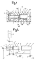
- FIG. 1 shows a designated pressure intensifier 1, which can be used to increase the pressure in a piston chamber of a (not shown here) working cylinder.
- a pressure booster can be installed, for example, in a die casting machine or a press.
- FIG. 1 Various lines are provided for integration into an arrangement for a die casting machine.
- FIG. 1 are the respective connections for supplying and discharging a hydraulic medium simplified indicated by dashes.
- approximately annular inflow space for example, two connections to the pressure medium supply can be seen.
- the individual interfaces and the connected components are in the following FIGS. 2 to 6 shown and explained.
- the printer translator 1 includes a pressure booster piston 4, which consists of a piston part and a coaxial thereto adjoining piston rod.
- the piston part has a larger diameter than the piston rod and defines on one end face the piston chamber designated 2.
- the annular space 3 of the printer translator On the other side of the piston part is the annular space 3 of the printer translator.
- a in the axial direction in the pressure translator housing slidably disposed valve seat 7 recognizable.
- This in FIG. 1 only schematically illustrated pressure booster housing may be composed of several cylinder sections.
- the locking or non-return valve which is integrated in the pressure intensifier and denoted by 6, is formed by the mutually movable pressure translating pistons 4 and valve seat 7.
- the pressure booster piston 4 and the valve seat 7 have sealing surfaces 25 and 26.
- the pressure booster piston 4 is formed at the valve seat 7 facing end side, apparently as a valve cone. This valve cone forms a seat valve together with the valve seat 7. In the closed position, the blocking or check valve brings about a blockage of the hydraulic fluid connection between the flow opening designated 8 and the inflow space 27 (cf. Fig. 4 and 6 ).
- the pressure booster piston has a bore 5 extending in the axial direction.
- this supply bore 5 has an approximately conical insertion section in the region of the piston chamber-side end face, to which a section with an approximately constant diameter adjoins.
- the bore 5 is designed as a blind hole; one or more through holes 21 arranged transversely to the axial direction serve for the hydraulic connection. These through bores 21 can be arranged at any desired angle to the axial direction, here by way of example 60 °. They connect the blind bore 5 in the pressure booster piston 4 with the inflow space 27 of the check valve 6.
- the valve seat 7 consisting of a single component has a smaller outer diameter on the side of the sealing surface 26 and a larger outer diameter on the side facing the outlet. These two different diameters form a hydraulically effective annular surface, which leads via a pressure difference to an axial force action in the direction of the basic position.
- this annular surface is connected to the tank. The acting on the remaining surfaces higher operating pressure then causes the return force on this area difference to keep the valve seat in the normal position.
- a shoulder 33 adjoining this annular surface serves to limit the stroke.
- FIG. 2 shows the printer translator 1 in an assembly for die casting.
- This arrangement has as a consumer via a working cylinder 12 in which a working piston 23 is slidably disposed.
- the arrangement has a hydraulic energy source 10, for example, an accumulator, which is connected via a line which is connected to the inflow space 27 of the check valve or check valve.
- the hydraulic energy source is connected to another working space of the arrangement.
- the line after an accumulator-Zuschaltventil 11 also open into the piston chamber 2 of the pressure booster 1.
- the hydraulic energy source 10 is connected via the accumulator-Zuschaltventil 11 and the check valve or check valve 6 with the working cylinder 12.
- the flow conditions in the accumulator-Zuschaltventil 11, the check valve or check valve 6 and the valve seat 7 thereby influence the maximum flow rate of the hydraulic medium.
- the pressure booster piston 4 is executed at the piston rod side end as a valve cone of the check valve or check valve 6.
- the valve seat 7 of the check valve 6 is axially displaceable, so that the pressure booster 1 together with the valve seat 7, the working pressure at the consumer, i. can increase in the cylinder 12.
- valve seat 7 Due to the previously mentioned hydraulic operative connection between the valve seat 7 and the connected via a hydraulic line to the tank T 1 annular surface for the surface difference at the valve seat keeps the valve seat 7 even at very high flow rate safely in the normal position.
- the flow opening 8 of the valve seat 7 can thereby remain free of mechanical installations, which increases the flow rate and the mechanical reliability of the construction.
- the hydraulic positioning additionally reduces the bounce of the valve seat during hard impact of the pressure booster piston 4 on the valve seat 7, since in contrast to the mechanical retention a defined force counteracts the bouncing of the valve seat 7.
- FIG. 2 In addition to the already mentioned tank T 1 are in FIG. 2 two further tanks (T, T 2 ) recognizable.
- the annular space 3 of the pressure booster is connected via a connecting line 18 with the annular space 22 of the working cylinder 12. This ensures that the respective annular spaces 3 and 22 are acted upon by means of an annular space valve 15 with a compressive bias.
- This pressure bias in the connection line 18 can be formed by means of a pressure divider by the hydraulic valves 15 and 17 or generated by a separate pressure relief or pressure reducing valve.
- a connection valve 13 for driving the annular space 3 is further arranged.
- the connecting line 18 between the Zuschaltventil 13 and annular space valve 15 is then connected via a feed valve 17 with a hydraulic power source P.
- the pressure feed can take place both from a second pressure accumulator or, in the extreme case, also from the accumulator 10 via the valves 11 and 16. This minimal variant is energetic but not optimal.
- a "differential valve" designated switching valve 16.
- the return of the working piston 23, the valve seat 7 and the pressure booster piston 4 is effected by pressure feed via a feed valve 17, with an open Zuschaltventil 13 and 14 open tank valve.
- the annulus valve 15 and the differential valve 16 must be closed.
- FIGS. 3 to 6 For a better understanding of the operation of the new pressure booster 1 show the FIGS. 3 to 6 the different sequences of a casting process.
- the basic pouring process is known per se to the person skilled in the art and has already been implemented in conventional casting arrangements for some time. Starting point is the in FIG. 2 illustrated basic position.
- both the pressure booster piston 4 By opening the valves 13, 14 and 17, both the pressure booster piston 4, the valve seat 7 and the casting piston 23 moved to the normal position. The remaining hydraulic valves remain closed.
- a first ancestor of the casting piston 23 takes place at a slow speed.
- the casting piston 23 moves after opening the valves 11 and 16 energy-saving with initially reduced casting force in the direction of a. All other valves remain closed during this ancestor phase.
- valves 11 and 15 By opening the valves 11 and 15, a fast ancestor of the casting piston then takes place with full casting force. All other valves are closed.
- the pressure booster piston 5 By opening the valve 13, the pressure booster piston 5 is set in motion.
- the check valve 6 is closed. This position is in FIG. 4 shown.
- the valve cone of the pressure booster piston 4 abuts on the valve seat 7.
- the conical sealing surface of the valve seat 7 is in the closed position, as is apparent, flat on also conical valve cone portion of the pressure booster piston 4, whereby an advantageous and practically leak-free barrier can be achieved.
- the valves 11 and 13 remain open in this step.
- the casting piston is moved further forward to release the casting from the solid mold half.
- the connection valve 13 of the pressure booster is closed.
- the pressure booster piston 4 stops.
- the valve seat 7 can move further forward in the a direction, which again creates a valve opening between the pressure booster piston 4 and the valve seat 7, i. the check valve 6 is now in an open position again.
Landscapes
- Engineering & Computer Science (AREA)
- Mechanical Engineering (AREA)
- Physics & Mathematics (AREA)
- Fluid Mechanics (AREA)
- General Engineering & Computer Science (AREA)
- Supply Devices, Intensifiers, Converters, And Telemotors (AREA)
- Braking Systems And Boosters (AREA)
- Fluid-Pressure Circuits (AREA)
- Fuel-Injection Apparatus (AREA)
- Details Of Reciprocating Pumps (AREA)
Description
Die Erfindung betrifft einen Druckübersetzer gemäss dem Oberbegriff von Anspruch 1, insbesondere einen Druckübersetzer in Antriebseinrichtungen für Druckgiessmaschinen. Weiter betrifft die Erfindung eine Anordnung zum Druckgiessen mit einem derartigen Druckübersetzer und einem Arbeits- oder Giesszylinder. Der Druckübersetzer kann aber auch in Antriebseinrichtungen für Pressen oder anderen Arbeitsmaschinen eingesetzt werden.The invention relates to a pressure intensifier according to the preamble of claim 1, in particular a pressure booster in drive means for die casting machines. Furthermore, the invention relates to an arrangement for die casting with such a pressure booster and a working or casting cylinder. The pressure booster can also be used in drive devices for presses or other machines.
Druckübersetzer mit einem Druckübersetzerkolben und einem darin integrierten Rückschlagventil oder mit einem externen Bypass-Rückschlagventil sind seit längerer Zeit bekannt und gebräuchlich. Ein solches Rückschlagventil verhindert den Rückfluss von Hydraulikmedium aus einem Hochdruckraum eines Verbrauchers zum Kolbenraum des Druckübersetzers. Ein Druckübersetzer mit einem in den Druckübersetzerkolben integrierten Rückschlagventil ist beispielsweise aus der
Die bekannten Lösungen sind gekennzeichnet durch einen behinderten Durchflussquerschnitt und relativ hohe Produktionskosten. Die im Rückschlagventil üblicherweise eingesetzte Federvorspannung ist zudem ausfallgefährdet.The known solutions are characterized by a disabled flow cross-section and relatively high production costs. The spring preload usually used in the check valve is also at risk of failure.
In der
Es ist daher eine Aufgabe der Erfindung, die Nachteile des Bekannten zu vermeiden und insbesondere einen Druckübersetzer zu schaffen, der einen einfachen und sicheren Betrieb ermöglicht.It is therefore an object of the invention to avoid the disadvantages of the known and in particular to provide a pressure booster, which allows easy and safe operation.
Diese Aufgabe wird erfindungsgemäss mit einem Druckübersetzer mit den Merkmalen des Patentanspruchs 1 gelöst.This object is achieved according to the invention with a pressure intensifier having the features of patent claim 1.
Dadurch, dass der Druckübersetzer einen Ventilsitz aufweist, der mit dem Druckübersetzerkolben in Wirkverbindung steht und so ein vorteilhaftes Rückschlagventil bildet, können mehrere Vorteile erreicht werden. Der Druckerüberbesetzer zeichnet sich durch eine kompakte und zugleich einfache Bauweise aus. Diese Lösung ist aber auch strömungstechnisch günstig. Das erfindungsgemässe Sperr- oder Rückschlagventil ermöglicht vergleichsweise grosse Strömungsquerschnitte in der Offenstellung. Die Giesseinrichtungen lässt sich dadurch dynamischer und leistungsfähiger betreiben.Characterized in that the pressure booster has a valve seat which is in operative connection with the pressure booster piston and so on forms advantageous check valve, several advantages can be achieved. The Printer Overloader is characterized by a compact and at the same time simple construction. This solution is also favorable in terms of flow. The inventive check valve or check valve allows comparatively large flow cross-sections in the open position. The casting facilities can thus be operated more dynamically and efficiently.
Der erwähnte Druckübersetzerkolben kann bevorzugt als Stufenkolben ausgestaltet sein, der im Wesentlichen aus einem in einem Zylinder aufgenommenen Kolbenteil und einer koaxial darin anschliessenden Kolbenstange mit einem geringeren Durchmesser als der Kolbenteil besteht. Der Zylinder ist dann im Bereich der dem Kolbenteil zugewandten Stirnseite verschlossen und bildet mit diesem einen als "Kolbenraum" bezeichneten Arbeitsraum. Dabei gibt der Zylinder im Bereich der Kolbenstange einen ringförmigen Arbeitsraum vor. Dieser Arbeitsraum wird nachfolgend als Ringraum des Druckübersetzers bezeichnet.The mentioned pressure booster piston may preferably be configured as a stepped piston, which essentially consists of a piston part accommodated in a cylinder and a piston rod connected coaxially therein with a smaller diameter than the piston part. The cylinder is then closed in the region of the piston part facing end side and forms with this a "piston chamber" designated working space. In this case, the cylinder in the region of the piston rod before an annular working space. This working space is referred to below as the annulus of the pressure booster.
In einer ersten Ausführungsform kann der Druckübersetzerkolben an einer dem Ventilsitz zugewandten Stirnseite als Ventilkegel mit einer Dichtfläche ausgebildet sein. Zusammen mit einer am Ventilsitz angeordneten korrespondierenden Dichtfläche kann ein Sitzventil gebildet werden. Der Druckübersetzerkolben kann somit in einer Schliessstellung am Ventilsitz dichtend anliegen.In a first embodiment, the pressure booster piston may be formed on a front side facing the valve seat as a valve cone with a sealing surface. Together with a valve seat arranged on the corresponding sealing surface, a seat valve can be formed. The pressure booster piston can thus rest tightly against the valve seat in a closed position.
Vorteilhaft kann es sein, wenn der Ventilsitz von einer Ausgangslage in axialer Richtung vorzugsweise begrenzt verschiebbar ist. Dies erlaubt in einem ersten Schritt einen Schliesshub des Druckübersetzerkolbens zum Schliessen des Sperr- oder Rückschlagventils, während in einem weiteren Schritt beim effektiven Arbeitshub des Druckübersetzerkolbens der Ventilsitz zusammen mit dem Druckübersetzerkolben verschoben wird.It may be advantageous if the valve seat is preferably limitedly displaceable from an initial position in the axial direction. This allows in a first step, a closing stroke of the pressure booster piston for closing the check valve or check valve, while in a further step in the effective Working stroke of the pressure booster piston, the valve seat is moved together with the pressure booster piston.
Wenn wie vorgängig erwähnt der Ventilsitz beispielsweise über eine konische Dichtfläche im Bereich der dem Druckübersetzerkolben zugewandten Stirnseite verfügt, auf welche der vorzugsweise komplementär ausgebildete Ventilkegel des Druckübersetzerkolbens in der Sperrstellung flächig aufliegt. Dadurch kann ein sicheres Schliessen des Sperr- oder Rückschlagventils sichergestellt werden.If, as previously mentioned, the valve seat has, for example, a conical sealing surface in the region of the end face facing the pressure booster piston, on which the preferably complementary valve cone of the pressure booster piston rests flat in the blocking position. As a result, a secure closure of the check valve or check valve can be ensured.
Grundsätzlich ist es möglich, den Ventilsitz unter Verwendung von mechanischen Federmitteln zum Erzeugen einer Vorspannkraft in einer Ausgangsposition zu halten. Besonders vorteilhaft kann es jedoch sein, wenn hydraulische Mittel vorgesehen sind, mit deren Hilfe der Ventilsitz hydraulisch in seiner Ausgangsposition gehalten werden kann.In principle, it is possible to hold the valve seat in an initial position using mechanical spring means for generating a biasing force. However, it may be particularly advantageous if hydraulic means are provided, by means of which the valve seat can be hydraulically held in its initial position.
Die hydraulischen Mittel können auf vorteilhafte Art und Weise eine Rückstellkraft erzeugen, mit welcher ein verschobener Ventilsitz automatisch wieder in seine Ausgangsposition zurückkehren kann. Mit dieser Anordnung sind mit Ausnahme des Ventilsitzes keine weiteren beweglichen mechanischen Bauteile nötig. Die Strömungsöffnung des Ventilkörpers kann somit frei von mechanischen Einbauten bleiben. Dadurch kann die Betriebssicherheit und die mechanische Zuverlässigkeit, sowie die Lebensdauer des Druckübersetzers erhöht werden. Durch eine hydraulische Positionierung kann zusätzlich die Prellneigung des Ventilsitzes beim harten Aufschlagen des Druckübersetzerkolbens auf den Ventilsitz reduziert werden.The hydraulic means can advantageously produce a restoring force with which a displaced valve seat can automatically return to its original position. With the exception of the valve seat, no further moving mechanical components are required with this arrangement. The flow opening of the valve body can thus remain free of mechanical installations. As a result, the reliability and mechanical reliability, as well as the life of the pressure booster can be increased. Hydraulic positioning can additionally reduce the bounce of the valve seat when the pressure translator piston is hit hard against the valve seat.
Der Ventilsitz kann mit einem Ringraum ausgestattet sein, welcher drucklos zu Tank verbunden ist. Dieser Ringraum des Ventilsitzes kann jedoch auch zu einer Druckquelle verbunden sein. Die Druckwirkung im Ringraum muss den Ventilsitz entgegen der Strömungskraft des Hauptmedienflusses in der Grundstellung halten.The valve seat can be equipped with an annular space which is connected without pressure to the tank. This annulus of the valve seat However, it can also be connected to a pressure source. The pressure effect in the annulus must keep the valve seat against the flow force of the main media flow in the basic position.
Vorteilhaft ist der Ventilsitz so ausgestaltet, dass die hydraulisch wirksamen Flächen am Ventilssitz, gebildet durch beispielsweise eine Ringfläche, zu einer Kraftwirkung des Ventilsitzes auf einen dem Druckübersetzerkolben zugewandten Hubanschlag führt. So kann beispielsweise der Ventilsitz so ausgestaltet sein, dass ein Verhältnis der Ringfläche der dem Druckübersetzerkolben zugewandten Seite des Ventilsitzes zur Ringfläche der dem Druckübersetzerkolben abgewandten Seite des Ventilsitzes aufweist, so dass im normalen Betriebszustand des Druckübersetzers der Ventilsitz in Richtung zum Druckübersetzerkolben und/oder in die Ausgangslage vorgespannt ist. Dabei sind die Ringflächen so bemessen, dass die resultierende Kraft aus dem Druck der dem Druckübersetzerkolben abgewandten Seite des Ventilsitzes, und der entsprechenden Ringfläche grösser ist als die resultierende Kraft aus dem Druck der dem Druckübersetzerkolben zugewandten Seite des Ventilsitzes mit der entsprechenden Ringfläche. Somit kann auf jedes weitere Element zur Vorspannung des Ventilsitzes verzichtet werden.Advantageously, the valve seat is configured such that the hydraulically effective surfaces on the valve seat, formed by, for example, an annular surface, leads to a force effect of the valve seat on a stroke stop facing the pressure booster piston. Thus, for example, the valve seat may be designed so that a ratio of the annular surface of the pressure translator piston side facing the valve seat to the annular surface of the pressure booster piston side facing away from the valve seat, so that in the normal operating condition of the pressure booster, the valve seat in the direction of the pressure booster piston and / or in the Starting position is biased. In this case, the annular surfaces are dimensioned such that the resultant force from the pressure of the side facing the pressure booster piston side of the valve seat, and the corresponding annular surface is greater than the resultant force from the pressure of the pressure booster piston side facing the valve seat with the corresponding annular surface. Thus, can be dispensed with any further element for biasing the valve seat.
Der Ventilsitz und/oder der Druckübersetzer können ein Begrenzungsmittel aufweist, welches den Hub des Ventilsitzes im Druckübersetzer begrenzt.The valve seat and / or the pressure booster may have a limiting means which limits the stroke of the valve seat in the pressure booster.
Das Begrenzungsmittel kann beispielsweise ein an der Aussenwand des Ventilsitzes angeordneter ringförmiger Kragen sein, welcher mit einer Ringnut des Druckübersetzer zusammenwirkt und so den Hub des Ventilsitzes im Druckübersetzer in einer robusten, einfachen und kostengünstigen Konstruktion begrenzt.The limiting means may for example be an annular collar arranged on the outer wall of the valve seat, which cooperates with an annular groove of the pressure booster and thus limits the stroke of the valve seat in the pressure booster in a robust, simple and cost-effective construction.
Der Druckübersetzerkolben kann eine vorzugsweise axiale Bohrung aufweisen, über welche ein Kolbenraum mit einem Akkumulator direkt oder indirekt verbunden oder verbindbar ist. Diese Ausführungsvariante erlaubt eine besonders grosszügige und damit verlustarme Dimensionierung der Bohrungen, welche den Kolbenraum des Druckübersetzers mit hydraulischem Druck versorgen. Dadurch wird ein sehr dynamisches Ansprechen des Druckübersetzerkolbens ermöglicht. Ein solcher Druckübersetzerkolben ist einfach herstellbar. Weiterhin sind mit dieser Anordnung eine besonders sichere Betriebsweise und eine günstige Strömungsführung möglich.The pressure booster piston may have a preferably axial bore, via which a piston chamber with a battery directly or indirectly connected or connectable. This embodiment allows a particularly generous and therefore low-loss sizing of the holes, which supply the piston chamber of the pressure booster with hydraulic pressure. This allows a very dynamic response of the pressure booster piston. Such a pressure booster piston is easy to produce. Furthermore, a particularly safe operation and a favorable flow guidance are possible with this arrangement.
Die Bohrung kann als Sackloch ausgestaltet sein, wobei die Bohrung ausgehend vom kolbenraumseitigen Ende des Druckübersetzerkolbens sich in axialer Richtung erstreckt. Der Bohrungsquerschnitt kann dabei vergleichsweise gross sein und beispielsweise zwischen 25% und 50% des Stangenquerschnitts erreichen. Die Bohrung muss nicht notwendigerweise über die gesamte Länge einen konstanten Durchmesser aufweisen. Die Bohrung kann auch einen beispielsweise konischen oder einen durch eine andere Formgebung sich verjüngenden Einführabschnitt aufweisen, der am kolbenraumseitigen Ende angeordnet ist und an dem in Richtung Kolbenstange ein Bohrabschnitt mit einem konstanten Durchmesser anschliesst.The bore may be configured as a blind hole, wherein the bore extending in the axial direction, starting from the piston-chamber-side end of the pressure booster piston. The bore cross section can be comparatively large and, for example, reach between 25% and 50% of the rod cross section. The bore does not necessarily have to have a constant diameter over its entire length. The bore may also have, for example, a conical or a tapered by a different shape insertion section, which is arranged at the piston chamber side end and adjoins the direction of the piston rod in a bore portion with a constant diameter.
Zum hydraulischen Verbinden des durch die Bohrung geschaffenen vorzugsweise zylindrischen Hohlraums mit dem Akkumulator und/oder mit dem Arbeitszylinder kann der Druckübersetzerkolben wenigstens einen in Bezug auf die axiale Richtung quer verlaufenden Durchlass, insbesondere in Form einer Bohrung aufweisen. Die Durchlassbohrung kann in einem rechten Winkel oder um einen beliebigen Neigungswinkel zur Längsmittelachse geneigt verlaufen. Der wenigstens eine Durchlass kann im Bereich des dem Ventilsitzes zugewandten Endes des Druckübersetzerkolbens angeordnet sein. Besonders vorteilhaft ist es, wenn mehrere, vorzugsweise gleichmässig über den Umfang verteilte Durchlasse vorgesehen sind. Die Durchlasse ermöglichen eine Verbindung der Bohrung mit einem Zuflussraum des Sperr- oder Rückschlagventils. Diese Durchlassbohrungen münden direkt in den Zuflussraum des Sperr- oder Rückschlagventils ohne die Dichtfläche des Druckübersetzerkolbens zu beeinträchtigen.For hydraulically connecting the preferably cylindrical cavity created by the bore to the accumulator and / or to the working cylinder, the pressure booster piston may have at least one passage extending transversely with respect to the axial direction, in particular in the form of a bore. The passage bore may be inclined at a right angle or at any inclination angle to the longitudinal center axis. The at least one passage can be arranged in the region of the valve seat facing the end of the pressure booster piston. It is particularly advantageous if several, preferably uniformly distributed over the circumference passages are provided. The passages allow a connection of the bore with an inflow space of the check valve or check valve. These passage holes open directly into the inflow space of the check valve or check valve without affecting the sealing surface of the pressure booster piston.
Die Auslösung des Druckübersetzerkolbens von einer Ausgangstellung am kolbenseitigen Anschlag in eine Arbeitsstellung mit geschlossenem Sitzventil kann durch ein schaltbares Druckübersetzer-Zuschaltventil am Ringraum des Druckübersetzers betätigbar sein.The triggering of the pressure booster piston from a starting position on the piston-side stop in a working position with a closed seat valve can be actuated by a switchable pressure booster Zuschaltventil the annulus of the pressure booster.
Der Druckübersetzer kann so ausgestaltet sein, dass zum Schliessen des Sperr- oder Rückschlagventils ein Schliesshub des Druckübersetzerkolbens ausführbar ist. Der Schliesshub des Druckübersetzerkolbens bildet die Ventilöffnung des Sperr- oder Rückschlagventils. Dabei wird unter einer Bewegung innerhalb des Schliesshubs verstanden, dass der Druckübersetzerkolben sich in Richtung des am Druckübersetzer nachgeschalteten Arbeitszylinders bewegt, dass jedoch aufgrund des noch offenen Sperr- oder Rückschlagventils noch kein zusätzlicher Druck im Kolbenraum des Arbeitszylinders erzeugt wird.The pressure booster can be designed so that a closing stroke of the pressure booster piston is executable to close the check valve or check valve. The closing stroke of the pressure booster piston forms the valve opening of the check valve or check valve. Here, a movement within the closing stroke is understood to mean that the pressure booster piston moves in the direction of the working cylinder connected downstream of the pressure booster, but that due to the still open check valve, no additional pressure is generated in the piston chamber of the working cylinder.
Ein weiterer Aspekt der Erfindung betrifft eine Anordnung zum Druckgiessen mit dem vorgängig beschriebenen Druckübersetzer. Die Anordnung weist weiter einen Arbeitszylinder auf, der zur Druckerhöhung im Kolbenraum des Arbeitszylinders mit dem Arbeitszylinder verbunden ist. Arbeitszylinder, Druckübersetzerkolben und Ventilsitz des Druckübersetzers können koaxial zueinander ausgerichtet sein.Another aspect of the invention relates to an arrangement for die casting with the previously described pressure booster. The arrangement further comprises a working cylinder, which is connected to the pressure increase in the piston chamber of the working cylinder with the working cylinder. Working cylinder, pressure booster piston and valve seat of the pressure booster can be aligned coaxially with each other.
Der Ringraum des Druckübersetzers kann derart über eine Verbindungsleitung mit dem Ringraum des Arbeitszylinders verbunden sein, dass die jeweiligen Ringräume mittels eines Ringraumventils mit einer Druckvorspannung beaufschlagbar sind. Dies hat den Vorteil, dass sowohl der Arbeitskolben wie auch der Druckübersetzer in seiner jeweiligen Wirkungsweise in einem weiten Anwendungsbereich beeinflussbar sind. Der Abgabedruck des Druckübersetzers, d.h. der Kolbendruck im Arbeitszylinder wird durch den Druck am Ringraum des Druckübersetzers gesenkt. Die Kraft-wirkung des Arbeitszylinders wird durch den Druck im Ringraum des Arbeitszylinders reduziert. Wenn beide Beeinflussungen zusammen wirken, ergibt sich eine weit stärkere Beeinflussung der Kraftwirkung des Arbeitskolbens, da der Ringraumdruck am Druckübersetzer auch senkend auf den Kolbendruck des Arbeitszylinders wirkt.The annular space of the pressure booster can be connected via a connecting line with the annular space of the working cylinder such that the respective annular spaces can be acted upon by means of an annular space valve with a pressure bias. This has the advantage that both the working piston as well as the pressure booster can be influenced in its respective mode of action in a wide range of applications. The discharge pressure of the pressure booster, i. the piston pressure in the working cylinder is lowered by the pressure at the annulus of the pressure booster. The force effect of the working cylinder is reduced by the pressure in the annular space of the working cylinder. If both influences interact together, the force effect of the working piston is much more pronounced, since the annular space pressure at the pressure booster also has a lowering effect on the piston pressure of the working cylinder.
Die Anordnung kann als hydraulische Energiequelle einen Druckakkumulator aufweisen. Dieser Akkumulator kann über eine Leitung an den Zuflussraum des Sperr- oder Rückschlagventils angeschlossen sein. Zusätzlich kann in den Zuflussraum des Sperr- oder Rückschlagventils über einen zweiten Anschluss mit einer weiteren Druckmittelquelle, beispielsweise in Form einer Hydraulikpumpe, ein Hydraulikmedium zu- oder allenfalls abgeführt werden. Diese Beschaltung ermöglicht es, bei einem relativ langsamen Bewegungsstart des Arbeitskolbens Hydraulikmedium von einer Hydraulikpumpe zu beziehen und dadurch ein sehr sanftes und sprungfreies Anfahren zu gewährleisten.The arrangement may have as a hydraulic energy source a pressure accumulator. This accumulator can be connected via a line to the inflow space of the check valve or check valve. In addition, in the inflow space of the check valve or check valve via a second connection with a further pressure medium source, for example in the form of a hydraulic pump, a hydraulic medium or at most be removed. This wiring makes it possible to obtain at a relatively slow start of movement of the working piston hydraulic fluid from a hydraulic pump, thereby ensuring a very smooth and jump-free start.
Für einen optimalen Ablauf des Giessprozesses kann es vorteilhaft sein, wenn in der erwähnten Verbindungsleitung weiter ein Zuschaltventil zum Ansteuern des Ringraums des Druckübersetzers angeordnet ist. Die Verbindungsleitung zwischen Zuschaltventil und Ringraumventil kann dabei über ein Einspeiseventil mit der hydraulischen Energiequelle verbunden oder verbindbar sein. Die Verbindungsleitung kann weiter zwischen Zuschaltventil und Ringraumventil mittels eines Differentialventils mit dem Zuflussraum des Sperr- oder Rückschlagventils verbunden oder verbindbar sein.For an optimal sequence of the casting process, it may be advantageous if a connecting valve for controlling the annular space of the pressure booster is further arranged in the mentioned connection line. The connecting line between the Zuschaltventil and annulus valve can via a feed valve with the hydraulic energy source connected or connectable. The connecting line can be further connected or connectable between the connecting valve and annular space valve by means of a differential valve with the inflow space of the check valve or check valve.
Der Ringraum des Druckübersetzers, der Ringraum des Arbeitszylinders und der Zuflussraum des Sperr- oder Rückschlagventils können derart miteinander über Leitungen verbunden sein, dass eine Rückbewegung des Arbeitskolbens, des Ventilsitzes und des Druckübersetzerkolbens des Druckübersetzers über eine Ventilanordnung enthaltend Einspeiseventil, Zuschaltventil und Tankventil auf einfache Art und Weise hervorgerufen werden kann. Diese Ausgestaltung hat weiter den Vorteil, dass über eine Ventilanordnung enthaltend ein offenes Einspeiseventil, ein offenes Zuschaltventil und ein geschlossenes Tankventil auf einfache Art und Weise rein hydraulisch die Rückbewegung des Arbeitskolbens, des Ventilsitzes und des Druckübersetzerkolbens hervorgerufen werden kann. Besonders üblicherweise eingesetzte Betätigungsstangen entfallen, welche einerseits ausfallgefärdet sind und den Durchfluss der Sperr- oder Rückschlagventils mindern.The annular space of the pressure booster, the annular space of the working cylinder and the inflow space of the check valve can be connected to each other via lines, that a return movement of the working piston, the valve seat and the pressure booster piston of the pressure booster via a valve assembly containing feed valve, Zuschaltventil and tank valve in a simple way and can be brought about. This refinement also has the advantage that the return movement of the working piston, of the valve seat and of the pressure booster piston can be brought about in a simple manner purely hydraulically via a valve arrangement containing an open feed valve, an open switch valve and a closed tank valve. Particularly commonly used actuating rods omitted, which are on the one hand default and reduce the flow of the check valve or check valve.
Ein weiterer Aspekt der Erfindung betrifft einen Druckübersetzer zur Druckerhöhung in einem Kolbenraum eines Arbeitszylinders, wobei ein Druckübersetzerkolben zusammen mit einem Ventilsitz einen Druckübersetzer bilden.Another aspect of the invention relates to a pressure booster for increasing the pressure in a piston chamber of a working cylinder, wherein a pressure booster piston together with a valve seat form a pressure booster.
Weitere Einzelmerkmale und Vorteile der Erfindung ergeben sich aus der nachfolgenden Beschreibung von Ausführungsbeispielen und aus den Zeichnungen. Es zeigen:
- Figur 1:
- eine vereinfachte Schnittdarstellung eines erfindungsgemässen Druckübersetzers,
- Figur 2:
- eine Prinzipdarstellung einer Anordnung zum Druckgiessen mit dem Druckübersetzer aus
Figur 1 in einer Grundstellung, - Figur 3:
- die
Anordnung gemäss Figur 2 nach einem ersten Arbeitsschritt in einem Giessprozess, - Figur 4:
- die Anordnung nach einem weiteren Arbeitsschritt mit dem Druckübersetzer in einer Schliessstellung zu Begin einer Nachdruckphase,
- Figur 5:
- die Anordnung während der Nachdruckphase mit zurückgelegtem Verdichtungshub, und
- Figur 6:
- die Anordnung in einem letzten Arbeitsschritt beim Ausstossen einer erstarrten Angusstablette.
- FIG. 1:
- a simplified sectional view of a pressure intensifier according to the invention,
- FIG. 2:
- a schematic diagram of an arrangement for die casting with the pressure booster from
FIG. 1 in a basic position, - FIG. 3:
- the arrangement according to
FIG. 2 after a first step in a casting process, - FIG. 4:
- the arrangement after a further working step with the pressure booster in a closed position at the beginning of a holding pressure phase,
- FIG. 5:
- the arrangement during the Nachdruckphase with zurückgestem Verdichtungshub, and
- FIG. 6:
- the arrangement in a final step in the ejection of a frozen Angußablette.
Zum Integrieren in eine Anordnung für eine Druckgiessmaschine sind verschiedene Leitungen vorgesehen. In
Der Druckerübersetzer 1 enthält einen Druckübersetzerkolben 4, der aus einem Kolbenteil und einer koaxial daran anschliessenden Kolbenstange besteht. Der Kolbenteil weist ersichtlicherweise einen grösseren Durchmesser als die Kolbenstange auf und definiert auf einer Stirnseite den mit 2 bezeichneten Kolbenraum. Auf der anderen Seite des Kolbenteils befindet sich der Ringraum 3 des Druckerübersetzers. Weiterhin ist in
Das im Drückübersetzer integrierte und mit 6 bezeichnete Sperr- oder Rückschlagventil wird durch die zueinander beweglichen Druckübersetzerkolben 4 und Ventilsitz 7 gebildet. Im vorliegenden Ausführungsbeispiel in Bezug auf die axiale Richtung etwa mittig befindet sich der Zuflussraum 27 des Sperr- oder Rückschlagventils 6. Wie aus
Der Druckübersetzerkolben weist eine in axialer Richtung verlaufende Bohrung 5 auf. Diese Versorgungsbohrung 5 weist ersichtlicherweise im Bereich der kolbenraumseitigen Stirnseite einen etwa konischen Einführabschnitt auf, an den ein Abschnitt mit einem etwa konstanten Durchmesser anschliesst. Die Bohrung 5 ist als Sackloch ausgestaltet; für die hydraulische Verbindung dienen eine oder mehrere quer zur Achsrichtung angeordnete Durchlassbohrungen 21. Diese Durchlassbohrungen 21 können in einem beliebigen Winkel zur Achsrichtung, hier beispielhaft 60°, angeordnet sein. Sie verbinden die Sackbohrung 5 im Druckübersetzerkolben 4 mit dem Zuflussraum 27 des Sperr- oder Rückschlagventils 6. Durch diese Ausgestaltung kann eine sehr hohe Durchflussleistung von der Energiequelle im Zuflussraum 27 zur Kolbenseite 2 des Druckübersetzerkolbens 4 gewährleistet werden, was wiederum eine hohe Dynamik des Druckübersetzers 1 ermöglicht.The pressure booster piston has a
Der aus einem einzigen Bauteil bestehende Ventilsitz 7 weist einen kleineren Aussendurchmesser auf Seite der Dichtfläche 26 und einen grösseren Aussendurchmesser auf der dem Auslass zugewandten Seite auf. Diese beiden unterschiedlichen Durchmesser bilden eine hydraulisch wirksame Ringfläche, welche über eine Druckdifferenz zu einer axialen Kraftwirkung in Richtung Grundstellung führt. Bevorzugt wird diese Ringfläche zu Tank verbunden. Der auf die restlichen Flächen wirkende höhere Betriebsdruck bewirkt dann über diese Flächendifferenz die Rückstellkraft, um den Ventilsitz in der Grundstellung zu halten. Eine an diese Ringfläche angrenzende Schulter 33 dient der Hubbegrenzung.The
Der Druckübersetzerkolben 4 ist am kolbenstangenseitigen Ende als Ventilkegel des Sperr- oder Rückschlagventil 6 ausgeführt. Der Ventilsitz 7 des Sperr- oder Rückschlagventil 6 ist axial verschiebbar, damit der Druckübersetzer 1 zusammen mit dem Ventilsitz 7 den Arbeitsdruck beim Verbraucher, d.h. im Arbeitszylinder 12 steigern kann.The
Durch die vorgängig erwähnte hydraulische Wirkverbindung zwischen Ventilsitz 7 und dem über eine Hydraulikleitung mit dem Tank T1 verbundenen Ringfläche für die Flächendifferenz am Ventilsitz hält den Ventilsitz 7 auch bei sehr hoher Strömungsgeschwindigkeit sicher in der Grundstellung. Die Strömungsöffnung 8 des Ventilsitzes 7 kann dadurch frei von mechanischen Einbauten bleiben, was die Durchflussleistung und die mechanische Zuverlässigkeit der Konstruktion steigert. Die hydraulische Positionierung reduziert zusätzlich die Prellneigung des Ventilsitzes beim harten Aufschlagen des Druckübersetzerkolbens 4 auf den Ventilsitz 7, da im Gegensatz zur mechanischen Rückhaltung eine definierte Kraft dem Prellen des Ventilsitzes 7 entgegen wirkt.Due to the previously mentioned hydraulic operative connection between the
Neben dem bereits erwähnten Tank T1 sind in
Zum besseren Verständnis der Wirkungsweise des neuen Druckübersetzers 1 zeigen die
In einem nächsten Schritt erfolgt ein erstes Vorfahren des Giesskolbens 23 in langsamer Geschwindigkeit. Dazu fährt der Giesskolben 23 nach dem Öffnen der Ventile 11 und 16 energiesparend mit zunächst reduzierter Giesskraft in Richtung a. Alle andern Ventile bleiben während dieser Vorfahrphase geschlossen.In a next step, a first ancestor of the
Durch Öffnen der Ventile 11 und 15 erfolgt dann ein schnelles Vorfahren des Giesskolbens mit voller Giesskraft. Alle anderen Ventile sind geschlossen.By opening the
Durch Öffnen des Ventils 13 wird der Druckübersetzerkolben 5 in Bewegung gesetzt. Beim Zusammentreffen des Druckübersetzerkolbens 4 mit dem Ventilsitz 7 wird das Sperr- oder Rückschlagventil 6 geschlossen. Diese Position ist in
Dann erfolgt eine Nachdruckphase (
Schliesslich wird in einem letzten Arbeitsschritt des Giessvorgangs der Giesskolben weiter vorwärts bewegt, um das Gussteil von der festen Formhälfte zu lösen. Das Zuschaltventil 13 des Druckübersetzers wird dazu geschlossen. Der Druckübersetzerkolben 4 bleibt stehen. Der Ventilsitz 7 kann sich jedoch weiter nach vorne in a-Richtung bewegen, was wieder eine Ventilöffnung zwischen Druckübersetzerkolben 4 und Ventilsitz 7 schafft, d.h. das Sperr- oder Rückschlagventil 6 ist nun wieder in einer offenstellung. Finally, in a final step of the casting process, the casting piston is moved further forward to release the casting from the solid mold half. The
Claims (20)
- A pressure booster (1) for increasing the pressure in a piston space (20) of a working cylinder (12), having a pressure booster piston (4), characterized in that the pressure booster (1) has a valve seat (7), the pressure booster piston (4) interacting with the valve seat (7) in order to form a shutoff or nonreturn valve (6).
- The pressure booster (1) as claimed in claim 1, characterized in that, on an end side which faces the valve seat (7), the pressure booster piston (4) is configured as a valve cone with a sealing face (25) which interacts with a sealing face (26) arranged on the valve seat (7) and forms a seat valve.
- The pressure booster (1) as claimed in claim 1 or 2, characterized in that the valve seat (7) can be displaced from an initial position in the axial direction (a).
- The pressure booster (1) as claimed in claim 3, characterized in that the valve seat (7) is configured in such a way that the hydraulically active faces on the valve seat (7), lead to a force action of the valve seat (7) on a stroke stop which faces the pressure booster piston (4).
- The pressure booster (1) as claimed in claim 3, characterized in that, in the normal operating state, the valve seat (7) is prestressed in the direction of the pressure booster piston (4) by means of a separate prestressing means.
- The pressure booster (1) as claimed in one of claims 3 to 5, characterized in that the valve seat (7) and/or the pressure booster (1) have/has a limiting means which limits the stroke of the valve seat (7) in the pressure booster (1).
- The pressure booster (1) as claimed in claim 6, characterized in that the limiting means is an annular collar (33) which is arranged on the outer wall of the valve seat (7), interacts with an annular groove (30) of the pressure booster (1) and thus limits the stroke of the valve seat (7) in the pressure booster (1).
- The pressure booster (1) as claimed in one of claims 1 to 6, characterized in that the pressure booster piston (4) has a hole (5), via which a piston space (2) is connected or can be connected directly or indirectly to an accumulator (10).
- The pressure booster (1) as claimed in claim 8, characterized in that the hole (5) is configured as a blind bore, the hole (5) extending in the axial direction (a) starting from the piston space-side end of the pressure booster piston (4).
- The pressure booster (1) as claimed in claim 8 or 9, characterized in that the pressure booster piston (4) has at least one passage (21), which extends transversely in relation to the axial direction, for the hydraulic connection of the cavity provided by the hole (5) to the accumulator (10) and/or to the working cylinder (12).
- The pressure booster (1) as claimed in one of claims 8 to 10, characterized in that the at least one passage (21) makes a connection of the hole (5) to an inflow space (27) of the shutoff valve (6) possible.
- The pressure booster (1) as claimed in one of claims 1 to 11, characterized in that, in order to trigger the pressure booster piston (4) from an initial position into a working position with a closed shutoff valve (6), a pressure booster adding valve (13) which is connected to an annular space (3) of the pressure booster (1) can be actuated.
- The pressure booster (1) as claimed in one of claims 1 to 12, characterized in that the pressure booster (1) is configured in such a way that a closing stroke of the pressure booster piston (4) can be carried out before the shutoff or nonreturn valve (6) is closed.
- The pressure booster (1) as claimed in one of claims 1 to 13, characterized in that a line (18) with an electrically actuated or actuable hydraulic valve (13) connects an annular space (3) of the pressure booster piston (4) to an annular space valve (15) to a tank (T2) or to a pressure prestressing means in the line (18).
- A die casting arrangement having a working cylinder (12) and a pressure booster (1) as claimed in one of claims 1 to 14, the pressure booster (1) being connected to the working cylinder (12) in order to increase the pressure in the piston space (20) of the working cylinder (12).
- The arrangement as claimed in claim 15, characterized in that the working cylinder (12), the pressure booster piston (4) and the valve seat (7) of the pressure booster (1) are oriented coaxially with respect to one another.
- The arrangement as claimed in claim 15 or 16, characterized in that an annular space (3) of the pressure booster (1) can be connected via a connecting line (18) to an annular space (22) of the working cylinder (12) in such a way that the respective annular spaces (3, 22) can be loaded with a pressure prestress by means of an annular space valve (15).
- The arrangement as claimed in claim 17, characterized in that, furthermore, an adding valve (13) is arranged in the connecting line (18) for actuating the annular space (3) of the pressure booster (1), and in that the connecting line (18) between the adding valve (13) and annular space valve (15) can be connected to a hydraulic energy source (P) via a supply valve (17).
- The arrangement as claimed in claim 17 or 18, characterized in that the connecting line (18) between the adding valve (13) and annular space valve (15) can be connected to an inflow space (27) of the shutoff or nonreturn valve (6) by means of a switching valve (16).
- The arrangement as claimed in claim 19, characterized in that the annular space (3) of the pressure booster (1), the annular space (22) of the working cylinder (12) and the inflow space (27) of the shutoff or nonreturn valve (6) are connected to one another via lines (18) in such a way that a return movement of the working cylinder (12), the valve seat (7) and the pressure booster piston (4) of the pressure booster (1) can be brought about via a valve arrangement comprising supply valve (17), adding valve (13) and tank valve (14).
Applications Claiming Priority (2)
| Application Number | Priority Date | Filing Date | Title |
|---|---|---|---|
| DE200810055542 DE102008055542A1 (en) | 2008-12-17 | 2008-12-17 | Pressure intensifier with integrated non-return valve |
| PCT/EP2009/067462 WO2010070073A2 (en) | 2008-12-17 | 2009-12-17 | Pressure booster and diecasting arrangement |
Publications (2)
| Publication Number | Publication Date |
|---|---|
| EP2365888A2 EP2365888A2 (en) | 2011-09-21 |
| EP2365888B1 true EP2365888B1 (en) | 2013-03-06 |
Family
ID=42220635
Family Applications (1)
| Application Number | Title | Priority Date | Filing Date |
|---|---|---|---|
| EP09795981A Active EP2365888B1 (en) | 2008-12-17 | 2009-12-17 | Pressure booster and diecasting arrangement |
Country Status (6)
| Country | Link |
|---|---|
| US (1) | US8887502B2 (en) |
| EP (1) | EP2365888B1 (en) |
| JP (1) | JP5675640B2 (en) |
| CN (1) | CN102256726B (en) |
| DE (1) | DE102008055542A1 (en) |
| WO (1) | WO2010070073A2 (en) |
Cited By (2)
| Publication number | Priority date | Publication date | Assignee | Title |
|---|---|---|---|---|
| DE102015202273A1 (en) | 2015-02-09 | 2016-08-11 | Oskar Frech Gmbh + Co. Kg | Pressure translator device and die casting machine |
| EP3421155A1 (en) | 2017-06-28 | 2019-01-02 | Parker Hannifin Manufacturing Germany GmbH & Co. KG | Hydraulic circuit device for a cold chamber casting machine |
Families Citing this family (3)
| Publication number | Priority date | Publication date | Assignee | Title |
|---|---|---|---|---|
| CN102949934B (en) * | 2012-11-14 | 2014-07-09 | 中冶海水淡化投资有限公司 | Reverse osmosis seawater desalination energy recovery device and switcher thereof |
| CN103671301B (en) * | 2013-12-03 | 2015-09-16 | 广东电网公司电力科学研究院 | A kind of mechanical small-displacement pressure transducer |
| US9926178B2 (en) | 2014-08-20 | 2018-03-27 | Crown Equipment Corporation | Actuator in a lift truck |
Family Cites Families (16)
| Publication number | Priority date | Publication date | Assignee | Title |
|---|---|---|---|---|
| JPS4636237B1 (en) * | 1968-05-16 | 1971-10-23 | ||
| CH497221A (en) * | 1968-09-30 | 1970-10-15 | Buehler Ag Geb | Die casting machine |
| JPS5819383B2 (en) * | 1977-02-15 | 1983-04-18 | 東芝機械株式会社 | injection molding equipment |
| DE2911074A1 (en) * | 1979-03-21 | 1980-09-25 | Knorr Bremse Gmbh | Braking system pressure amplifier - has spring holding valve body off inlet seat when non-pressurised |
| DE3879285T2 (en) * | 1987-06-13 | 1993-07-01 | Honda Motor Co Ltd | HYDRAULIC CHECKING PROCEDURE FOR TOOLS. |
| JPH02211965A (en) * | 1988-10-31 | 1990-08-23 | Toshiba Mach Co Ltd | Die clamping cylinder device |
| CA2001707C (en) * | 1989-10-27 | 1993-10-12 | Jophn De Kok | Air-oil pressure intensifier cylinder |
| US4993226A (en) * | 1989-11-20 | 1991-02-19 | John De Kok | Multi-piston air-oil pressure intensifier with automatically variable working stroke length |
| DE4302235A1 (en) * | 1992-02-01 | 1993-08-19 | Tox Pressotechnik Gmbh | High pressure hydraulic unit esp. hydropneumatic pressure converter |
| JPH0636237A (en) | 1992-07-20 | 1994-02-10 | Alps Electric Co Ltd | Magnetoresistance effect-type head |
| JP3182708B2 (en) * | 1993-07-13 | 2001-07-03 | 株式会社名機製作所 | Hydraulic circuit of booster ram type clamping device |
| DE4344340C2 (en) * | 1993-12-23 | 1995-11-16 | Krauss Maffei Ag | Mold closing device for an injection molding machine |
| JP4048875B2 (en) * | 2002-08-14 | 2008-02-20 | 宇部興産機械株式会社 | INJECTION MOLDING CONTROL METHOD AND CONTROL DEVICE THEREOF |
| ITMI20040769A1 (en) * | 2004-04-20 | 2004-07-20 | Idra Casting Machines S P A | INJECTION GROUP WITH PRESSURE MULTIPLIER FOR DIE-CASTING MACHINES AND DIE-CASTING MACHINE PROVIDED WITH THAT INJECTION GROUP |
| ATE471460T1 (en) * | 2004-10-15 | 2010-07-15 | Bosch Rexroth Ag | PRE-CONTROLLED CHECK VALVE |
| CN101239375A (en) * | 2008-03-04 | 2008-08-13 | 苏州意特机械有限公司 | Double-pressurization fast mold locking/unlocking system |
-
2008
- 2008-12-17 DE DE200810055542 patent/DE102008055542A1/en not_active Withdrawn
-
2009
- 2009-12-17 CN CN200980150786.2A patent/CN102256726B/en active Active
- 2009-12-17 WO PCT/EP2009/067462 patent/WO2010070073A2/en active Application Filing
- 2009-12-17 EP EP09795981A patent/EP2365888B1/en active Active
- 2009-12-17 US US13/140,133 patent/US8887502B2/en active Active
- 2009-12-17 JP JP2011541456A patent/JP5675640B2/en active Active
Cited By (4)
| Publication number | Priority date | Publication date | Assignee | Title |
|---|---|---|---|---|
| DE102015202273A1 (en) | 2015-02-09 | 2016-08-11 | Oskar Frech Gmbh + Co. Kg | Pressure translator device and die casting machine |
| US11015619B2 (en) | 2015-02-09 | 2021-05-25 | Oskar Frech Gmbh + Co. Kg | Pressure intensifier device, diecasting machine casting unit and operating method |
| US11649836B2 (en) | 2015-02-09 | 2023-05-16 | Oskar Frech Gmbh + Co. Kg | Pressure intensifier device, diecasting machine casting unit and operating method |
| EP3421155A1 (en) | 2017-06-28 | 2019-01-02 | Parker Hannifin Manufacturing Germany GmbH & Co. KG | Hydraulic circuit device for a cold chamber casting machine |
Also Published As
| Publication number | Publication date |
|---|---|
| EP2365888A2 (en) | 2011-09-21 |
| US8887502B2 (en) | 2014-11-18 |
| WO2010070073A2 (en) | 2010-06-24 |
| JP2012512033A (en) | 2012-05-31 |
| CN102256726A (en) | 2011-11-23 |
| JP5675640B2 (en) | 2015-02-25 |
| CN102256726B (en) | 2014-12-24 |
| DE102008055542A1 (en) | 2010-07-01 |
| WO2010070073A3 (en) | 2010-10-28 |
| US20110247485A1 (en) | 2011-10-13 |
Similar Documents
| Publication | Publication Date | Title |
|---|---|---|
| EP1636484B1 (en) | Injector for internal combustion engines | |
| EP1598551B1 (en) | Fuel injection device | |
| EP2365888B1 (en) | Pressure booster and diecasting arrangement | |
| EP1853813A1 (en) | Injection nozzle | |
| DE2608791C2 (en) | ||
| DE10037527A1 (en) | Piezoelectric injection device for motor vehicle common rail fuel injection system, has one-way valve to allow flow of fluid from overflow chamber to piezo pump chamber | |
| EP2852754A1 (en) | Injector of a fuel injection system | |
| WO2010040511A1 (en) | Pressure limiting and suction valve unit | |
| WO2007000371A1 (en) | Injector with a pressure intensifier that can be switched on | |
| DE19902816B4 (en) | Pressure drop passage for a fuel injector with a trapped volume nozzle assembly | |
| EP1984629A1 (en) | Hydraulic control arrangement with regeneration and lowering brake valve | |
| EP2354526B1 (en) | Fuel injector | |
| EP1185785B1 (en) | Injection system | |
| EP2743493A2 (en) | Fuel injector | |
| DE2322354A1 (en) | WORK CYLINDERS, IN PARTICULAR HYDRAULIC CYLINDERS, WITH A DAMPING DEVICE FOR THE END OF THE WORKING STROKE OF THE PISTON | |
| DE60111164T2 (en) | Fuel injection valve with piezoelectric actuator | |
| EP1655477B1 (en) | Electrohydraulic servovalve | |
| EP0932783B1 (en) | Reduction and control valve | |
| DE19923422C2 (en) | Electronic injection system | |
| EP1704322B1 (en) | Injection nozzle | |
| DE102018200565A1 (en) | Injector for metering gaseous fuel, Gaseinblassystem with such an injector and method for operating this injector | |
| DE102006013704A1 (en) | Fuel injector, e.g. for a motor vehicle, has an injector body, a jet body and an actuator for operating a needle-shaped injection valve element | |
| EP3184803B1 (en) | Fuel injector | |
| DE102004024354A1 (en) | Hydraulic drive for a punch of forming machine has an active surface acting in the driving direction and delimiting an annular chamber which is connected to a switching valve | |
| EP1519032A1 (en) | Fuel injector |
Legal Events
| Date | Code | Title | Description |
|---|---|---|---|
| PUAI | Public reference made under article 153(3) epc to a published international application that has entered the european phase |
Free format text: ORIGINAL CODE: 0009012 |
|
| 17P | Request for examination filed |
Effective date: 20110530 |
|
| AK | Designated contracting states |
Kind code of ref document: A2 Designated state(s): AT BE BG CH CY CZ DE DK EE ES FI FR GB GR HR HU IE IS IT LI LT LU LV MC MK MT NL NO PL PT RO SE SI SK SM TR |
|
| DAX | Request for extension of the european patent (deleted) | ||
| RIC1 | Information provided on ipc code assigned before grant |
Ipc: B22D 17/32 20060101AFI20120515BHEP Ipc: F15B 3/00 20060101ALI20120515BHEP Ipc: B22D 17/20 20060101ALI20120515BHEP |
|
| GRAP | Despatch of communication of intention to grant a patent |
Free format text: ORIGINAL CODE: EPIDOSNIGR1 |
|
| GRAP | Despatch of communication of intention to grant a patent |
Free format text: ORIGINAL CODE: EPIDOSNIGR1 |
|
| GRAS | Grant fee paid |
Free format text: ORIGINAL CODE: EPIDOSNIGR3 |
|
| GRAA | (expected) grant |
Free format text: ORIGINAL CODE: 0009210 |
|
| AK | Designated contracting states |
Kind code of ref document: B1 Designated state(s): AT BE BG CH CY CZ DE DK EE ES FI FR GB GR HR HU IE IS IT LI LT LU LV MC MK MT NL NO PL PT RO SE SI SK SM TR |
|
| REG | Reference to a national code |
Ref country code: GB Ref legal event code: FG4D Free format text: NOT ENGLISH |
|
| REG | Reference to a national code |
Ref country code: AT Ref legal event code: REF Ref document number: 599303 Country of ref document: AT Kind code of ref document: T Effective date: 20130315 Ref country code: CH Ref legal event code: EP |
|
| REG | Reference to a national code |
Ref country code: IE Ref legal event code: FG4D Free format text: LANGUAGE OF EP DOCUMENT: GERMAN |
|
| REG | Reference to a national code |
Ref country code: DE Ref legal event code: R096 Ref document number: 502009006428 Country of ref document: DE Effective date: 20130502 |
|
| PG25 | Lapsed in a contracting state [announced via postgrant information from national office to epo] |
Ref country code: NO Free format text: LAPSE BECAUSE OF FAILURE TO SUBMIT A TRANSLATION OF THE DESCRIPTION OR TO PAY THE FEE WITHIN THE PRESCRIBED TIME-LIMIT Effective date: 20130606 Ref country code: LT Free format text: LAPSE BECAUSE OF FAILURE TO SUBMIT A TRANSLATION OF THE DESCRIPTION OR TO PAY THE FEE WITHIN THE PRESCRIBED TIME-LIMIT Effective date: 20130306 Ref country code: ES Free format text: LAPSE BECAUSE OF FAILURE TO SUBMIT A TRANSLATION OF THE DESCRIPTION OR TO PAY THE FEE WITHIN THE PRESCRIBED TIME-LIMIT Effective date: 20130617 Ref country code: SE Free format text: LAPSE BECAUSE OF FAILURE TO SUBMIT A TRANSLATION OF THE DESCRIPTION OR TO PAY THE FEE WITHIN THE PRESCRIBED TIME-LIMIT Effective date: 20130306 Ref country code: BG Free format text: LAPSE BECAUSE OF FAILURE TO SUBMIT A TRANSLATION OF THE DESCRIPTION OR TO PAY THE FEE WITHIN THE PRESCRIBED TIME-LIMIT Effective date: 20130606 |
|
| REG | Reference to a national code |
Ref country code: NL Ref legal event code: VDEP Effective date: 20130306 |
|
| REG | Reference to a national code |
Ref country code: LT Ref legal event code: MG4D |
|
| PG25 | Lapsed in a contracting state [announced via postgrant information from national office to epo] |
Ref country code: SI Free format text: LAPSE BECAUSE OF FAILURE TO SUBMIT A TRANSLATION OF THE DESCRIPTION OR TO PAY THE FEE WITHIN THE PRESCRIBED TIME-LIMIT Effective date: 20130306 Ref country code: LV Free format text: LAPSE BECAUSE OF FAILURE TO SUBMIT A TRANSLATION OF THE DESCRIPTION OR TO PAY THE FEE WITHIN THE PRESCRIBED TIME-LIMIT Effective date: 20130306 Ref country code: GR Free format text: LAPSE BECAUSE OF FAILURE TO SUBMIT A TRANSLATION OF THE DESCRIPTION OR TO PAY THE FEE WITHIN THE PRESCRIBED TIME-LIMIT Effective date: 20130607 Ref country code: FI Free format text: LAPSE BECAUSE OF FAILURE TO SUBMIT A TRANSLATION OF THE DESCRIPTION OR TO PAY THE FEE WITHIN THE PRESCRIBED TIME-LIMIT Effective date: 20130306 |
|
| PG25 | Lapsed in a contracting state [announced via postgrant information from national office to epo] |
Ref country code: HR Free format text: LAPSE BECAUSE OF FAILURE TO SUBMIT A TRANSLATION OF THE DESCRIPTION OR TO PAY THE FEE WITHIN THE PRESCRIBED TIME-LIMIT Effective date: 20130306 |
|
| PG25 | Lapsed in a contracting state [announced via postgrant information from national office to epo] |
Ref country code: RO Free format text: LAPSE BECAUSE OF FAILURE TO SUBMIT A TRANSLATION OF THE DESCRIPTION OR TO PAY THE FEE WITHIN THE PRESCRIBED TIME-LIMIT Effective date: 20130306 Ref country code: SK Free format text: LAPSE BECAUSE OF FAILURE TO SUBMIT A TRANSLATION OF THE DESCRIPTION OR TO PAY THE FEE WITHIN THE PRESCRIBED TIME-LIMIT Effective date: 20130306 Ref country code: IS Free format text: LAPSE BECAUSE OF FAILURE TO SUBMIT A TRANSLATION OF THE DESCRIPTION OR TO PAY THE FEE WITHIN THE PRESCRIBED TIME-LIMIT Effective date: 20130706 Ref country code: NL Free format text: LAPSE BECAUSE OF FAILURE TO SUBMIT A TRANSLATION OF THE DESCRIPTION OR TO PAY THE FEE WITHIN THE PRESCRIBED TIME-LIMIT Effective date: 20130306 Ref country code: EE Free format text: LAPSE BECAUSE OF FAILURE TO SUBMIT A TRANSLATION OF THE DESCRIPTION OR TO PAY THE FEE WITHIN THE PRESCRIBED TIME-LIMIT Effective date: 20130306 Ref country code: CZ Free format text: LAPSE BECAUSE OF FAILURE TO SUBMIT A TRANSLATION OF THE DESCRIPTION OR TO PAY THE FEE WITHIN THE PRESCRIBED TIME-LIMIT Effective date: 20130306 Ref country code: PT Free format text: LAPSE BECAUSE OF FAILURE TO SUBMIT A TRANSLATION OF THE DESCRIPTION OR TO PAY THE FEE WITHIN THE PRESCRIBED TIME-LIMIT Effective date: 20130708 |
|
| PG25 | Lapsed in a contracting state [announced via postgrant information from national office to epo] |
Ref country code: PL Free format text: LAPSE BECAUSE OF FAILURE TO SUBMIT A TRANSLATION OF THE DESCRIPTION OR TO PAY THE FEE WITHIN THE PRESCRIBED TIME-LIMIT Effective date: 20130306 |
|
| PLBE | No opposition filed within time limit |
Free format text: ORIGINAL CODE: 0009261 |
|
| STAA | Information on the status of an ep patent application or granted ep patent |
Free format text: STATUS: NO OPPOSITION FILED WITHIN TIME LIMIT |
|
| PG25 | Lapsed in a contracting state [announced via postgrant information from national office to epo] |
Ref country code: DK Free format text: LAPSE BECAUSE OF FAILURE TO SUBMIT A TRANSLATION OF THE DESCRIPTION OR TO PAY THE FEE WITHIN THE PRESCRIBED TIME-LIMIT Effective date: 20130306 |
|
| 26N | No opposition filed |
Effective date: 20131209 |
|
| REG | Reference to a national code |
Ref country code: DE Ref legal event code: R097 Ref document number: 502009006428 Country of ref document: DE Effective date: 20131209 |
|
| BERE | Be: lapsed |
Owner name: BUHLER DRUCKGUSS A.G. Effective date: 20131231 |
|
| REG | Reference to a national code |
Ref country code: CH Ref legal event code: PL |
|
| GBPC | Gb: european patent ceased through non-payment of renewal fee |
Effective date: 20131217 |
|
| PG25 | Lapsed in a contracting state [announced via postgrant information from national office to epo] |
Ref country code: LU Free format text: LAPSE BECAUSE OF FAILURE TO SUBMIT A TRANSLATION OF THE DESCRIPTION OR TO PAY THE FEE WITHIN THE PRESCRIBED TIME-LIMIT Effective date: 20131217 |
|
| REG | Reference to a national code |
Ref country code: IE Ref legal event code: MM4A |
|
| REG | Reference to a national code |
Ref country code: FR Ref legal event code: ST Effective date: 20140829 |
|
| PG25 | Lapsed in a contracting state [announced via postgrant information from national office to epo] |
Ref country code: IE Free format text: LAPSE BECAUSE OF NON-PAYMENT OF DUE FEES Effective date: 20131217 Ref country code: CH Free format text: LAPSE BECAUSE OF NON-PAYMENT OF DUE FEES Effective date: 20131231 Ref country code: BE Free format text: LAPSE BECAUSE OF NON-PAYMENT OF DUE FEES Effective date: 20131231 Ref country code: LI Free format text: LAPSE BECAUSE OF NON-PAYMENT OF DUE FEES Effective date: 20131231 |
|
| PG25 | Lapsed in a contracting state [announced via postgrant information from national office to epo] |
Ref country code: FR Free format text: LAPSE BECAUSE OF NON-PAYMENT OF DUE FEES Effective date: 20131231 Ref country code: GB Free format text: LAPSE BECAUSE OF NON-PAYMENT OF DUE FEES Effective date: 20131217 |
|
| PG25 | Lapsed in a contracting state [announced via postgrant information from national office to epo] |
Ref country code: MC Free format text: LAPSE BECAUSE OF FAILURE TO SUBMIT A TRANSLATION OF THE DESCRIPTION OR TO PAY THE FEE WITHIN THE PRESCRIBED TIME-LIMIT Effective date: 20130306 |
|
| PG25 | Lapsed in a contracting state [announced via postgrant information from national office to epo] |
Ref country code: SM Free format text: LAPSE BECAUSE OF FAILURE TO SUBMIT A TRANSLATION OF THE DESCRIPTION OR TO PAY THE FEE WITHIN THE PRESCRIBED TIME-LIMIT Effective date: 20130306 |
|
| PG25 | Lapsed in a contracting state [announced via postgrant information from national office to epo] |
Ref country code: CY Free format text: LAPSE BECAUSE OF FAILURE TO SUBMIT A TRANSLATION OF THE DESCRIPTION OR TO PAY THE FEE WITHIN THE PRESCRIBED TIME-LIMIT Effective date: 20130306 Ref country code: TR Free format text: LAPSE BECAUSE OF FAILURE TO SUBMIT A TRANSLATION OF THE DESCRIPTION OR TO PAY THE FEE WITHIN THE PRESCRIBED TIME-LIMIT Effective date: 20130306 |
|
| PG25 | Lapsed in a contracting state [announced via postgrant information from national office to epo] |
Ref country code: HU Free format text: LAPSE BECAUSE OF FAILURE TO SUBMIT A TRANSLATION OF THE DESCRIPTION OR TO PAY THE FEE WITHIN THE PRESCRIBED TIME-LIMIT; INVALID AB INITIO Effective date: 20091217 Ref country code: MK Free format text: LAPSE BECAUSE OF FAILURE TO SUBMIT A TRANSLATION OF THE DESCRIPTION OR TO PAY THE FEE WITHIN THE PRESCRIBED TIME-LIMIT Effective date: 20130306 |
|
| PG25 | Lapsed in a contracting state [announced via postgrant information from national office to epo] |
Ref country code: MT Free format text: LAPSE BECAUSE OF FAILURE TO SUBMIT A TRANSLATION OF THE DESCRIPTION OR TO PAY THE FEE WITHIN THE PRESCRIBED TIME-LIMIT Effective date: 20130306 |
|
| REG | Reference to a national code |
Ref country code: AT Ref legal event code: MM01 Ref document number: 599303 Country of ref document: AT Kind code of ref document: T Effective date: 20141217 |
|
| PG25 | Lapsed in a contracting state [announced via postgrant information from national office to epo] |
Ref country code: AT Free format text: LAPSE BECAUSE OF NON-PAYMENT OF DUE FEES Effective date: 20141217 |
|
| P01 | Opt-out of the competence of the unified patent court (upc) registered |
Effective date: 20230523 |
|
| PGFP | Annual fee paid to national office [announced via postgrant information from national office to epo] |
Ref country code: DE Payment date: 20231214 Year of fee payment: 15 |
|
| PGFP | Annual fee paid to national office [announced via postgrant information from national office to epo] |
Ref country code: IT Payment date: 20231229 Year of fee payment: 15 |