EP2365254A2 - Climatiseur - Google Patents
Climatiseur Download PDFInfo
- Publication number
- EP2365254A2 EP2365254A2 EP11157169A EP11157169A EP2365254A2 EP 2365254 A2 EP2365254 A2 EP 2365254A2 EP 11157169 A EP11157169 A EP 11157169A EP 11157169 A EP11157169 A EP 11157169A EP 2365254 A2 EP2365254 A2 EP 2365254A2
- Authority
- EP
- European Patent Office
- Prior art keywords
- air conditioner
- cover
- outdoor
- distribution device
- conditioner according
- Prior art date
- Legal status (The legal status is an assumption and is not a legal conclusion. Google has not performed a legal analysis and makes no representation as to the accuracy of the status listed.)
- Ceased
Links
- 239000003507 refrigerant Substances 0.000 claims abstract description 85
- 239000007788 liquid Substances 0.000 claims description 21
- 238000009434 installation Methods 0.000 claims description 18
- 230000000712 assembly Effects 0.000 claims description 16
- 238000000429 assembly Methods 0.000 claims description 16
- 238000004891 communication Methods 0.000 claims description 7
- 238000000034 method Methods 0.000 claims description 6
- 239000000758 substrate Substances 0.000 claims description 5
- 238000004378 air conditioning Methods 0.000 description 10
- 238000001816 cooling Methods 0.000 description 6
- 230000000694 effects Effects 0.000 description 3
- 238000010438 heat treatment Methods 0.000 description 3
- 238000012986 modification Methods 0.000 description 3
- 230000004048 modification Effects 0.000 description 3
- 239000000470 constituent Substances 0.000 description 2
- 238000010586 diagram Methods 0.000 description 2
- 238000007789 sealing Methods 0.000 description 2
- 238000003466 welding Methods 0.000 description 2
- 238000007906 compression Methods 0.000 description 1
- 238000007791 dehumidification Methods 0.000 description 1
- 230000001419 dependent effect Effects 0.000 description 1
- 230000006866 deterioration Effects 0.000 description 1
- 238000007599 discharging Methods 0.000 description 1
- 230000002349 favourable effect Effects 0.000 description 1
- 238000001914 filtration Methods 0.000 description 1
- 238000001746 injection moulding Methods 0.000 description 1
- 238000003780 insertion Methods 0.000 description 1
- 230000037431 insertion Effects 0.000 description 1
- 239000000126 substance Substances 0.000 description 1
Images


Classifications
-
- F—MECHANICAL ENGINEERING; LIGHTING; HEATING; WEAPONS; BLASTING
- F25—REFRIGERATION OR COOLING; COMBINED HEATING AND REFRIGERATION SYSTEMS; HEAT PUMP SYSTEMS; MANUFACTURE OR STORAGE OF ICE; LIQUEFACTION SOLIDIFICATION OF GASES
- F25B—REFRIGERATION MACHINES, PLANTS OR SYSTEMS; COMBINED HEATING AND REFRIGERATION SYSTEMS; HEAT PUMP SYSTEMS
- F25B41/00—Fluid-circulation arrangements
- F25B41/40—Fluid line arrangements
- F25B41/42—Arrangements for diverging or converging flows, e.g. branch lines or junctions
-
- F—MECHANICAL ENGINEERING; LIGHTING; HEATING; WEAPONS; BLASTING
- F24—HEATING; RANGES; VENTILATING
- F24F—AIR-CONDITIONING; AIR-HUMIDIFICATION; VENTILATION; USE OF AIR CURRENTS FOR SCREENING
- F24F3/00—Air-conditioning systems in which conditioned primary air is supplied from one or more central stations to distributing units in the rooms or spaces where it may receive secondary treatment; Apparatus specially designed for such systems
- F24F3/06—Air-conditioning systems in which conditioned primary air is supplied from one or more central stations to distributing units in the rooms or spaces where it may receive secondary treatment; Apparatus specially designed for such systems characterised by the arrangements for the supply of heat-exchange fluid for the subsequent treatment of primary air in the room units
- F24F3/065—Air-conditioning systems in which conditioned primary air is supplied from one or more central stations to distributing units in the rooms or spaces where it may receive secondary treatment; Apparatus specially designed for such systems characterised by the arrangements for the supply of heat-exchange fluid for the subsequent treatment of primary air in the room units with a plurality of evaporators or condensers
-
- F—MECHANICAL ENGINEERING; LIGHTING; HEATING; WEAPONS; BLASTING
- F24—HEATING; RANGES; VENTILATING
- F24F—AIR-CONDITIONING; AIR-HUMIDIFICATION; VENTILATION; USE OF AIR CURRENTS FOR SCREENING
- F24F1/00—Room units for air-conditioning, e.g. separate or self-contained units or units receiving primary air from a central station
- F24F1/06—Separate outdoor units, e.g. outdoor unit to be linked to a separate room comprising a compressor and a heat exchanger
- F24F1/26—Refrigerant piping
- F24F1/30—Refrigerant piping for use inside the separate outdoor units
-
- F—MECHANICAL ENGINEERING; LIGHTING; HEATING; WEAPONS; BLASTING
- F25—REFRIGERATION OR COOLING; COMBINED HEATING AND REFRIGERATION SYSTEMS; HEAT PUMP SYSTEMS; MANUFACTURE OR STORAGE OF ICE; LIQUEFACTION SOLIDIFICATION OF GASES
- F25B—REFRIGERATION MACHINES, PLANTS OR SYSTEMS; COMBINED HEATING AND REFRIGERATION SYSTEMS; HEAT PUMP SYSTEMS
- F25B2313/00—Compression machines, plants or systems with reversible cycle not otherwise provided for
- F25B2313/006—Compression machines, plants or systems with reversible cycle not otherwise provided for two pipes connecting the outdoor side to the indoor side with multiple indoor units
-
- F—MECHANICAL ENGINEERING; LIGHTING; HEATING; WEAPONS; BLASTING
- F25—REFRIGERATION OR COOLING; COMBINED HEATING AND REFRIGERATION SYSTEMS; HEAT PUMP SYSTEMS; MANUFACTURE OR STORAGE OF ICE; LIQUEFACTION SOLIDIFICATION OF GASES
- F25B—REFRIGERATION MACHINES, PLANTS OR SYSTEMS; COMBINED HEATING AND REFRIGERATION SYSTEMS; HEAT PUMP SYSTEMS
- F25B2313/00—Compression machines, plants or systems with reversible cycle not otherwise provided for
- F25B2313/007—Compression machines, plants or systems with reversible cycle not otherwise provided for three pipes connecting the outdoor side to the indoor side with multiple indoor units
-
- F—MECHANICAL ENGINEERING; LIGHTING; HEATING; WEAPONS; BLASTING
- F25—REFRIGERATION OR COOLING; COMBINED HEATING AND REFRIGERATION SYSTEMS; HEAT PUMP SYSTEMS; MANUFACTURE OR STORAGE OF ICE; LIQUEFACTION SOLIDIFICATION OF GASES
- F25B—REFRIGERATION MACHINES, PLANTS OR SYSTEMS; COMBINED HEATING AND REFRIGERATION SYSTEMS; HEAT PUMP SYSTEMS
- F25B2313/00—Compression machines, plants or systems with reversible cycle not otherwise provided for
- F25B2313/023—Compression machines, plants or systems with reversible cycle not otherwise provided for using multiple indoor units
-
- F—MECHANICAL ENGINEERING; LIGHTING; HEATING; WEAPONS; BLASTING
- F25—REFRIGERATION OR COOLING; COMBINED HEATING AND REFRIGERATION SYSTEMS; HEAT PUMP SYSTEMS; MANUFACTURE OR STORAGE OF ICE; LIQUEFACTION SOLIDIFICATION OF GASES
- F25B—REFRIGERATION MACHINES, PLANTS OR SYSTEMS; COMBINED HEATING AND REFRIGERATION SYSTEMS; HEAT PUMP SYSTEMS
- F25B2600/00—Control issues
- F25B2600/25—Control of valves
- F25B2600/2513—Expansion valves
Definitions
- An air conditioner is disclosed herein.
- Air conditioners are known. However, they suffer from various disadvantages.
- An air conditioner according to the present invention is defined in independent claim 1.
- a method of operating an apparatus as described herein is defined in independent claim 16.
- the dependent claims relate to further aspects of the invention.
- FIG. 1 is a schematic view of an air conditioner in accordance with an embodiment
- FIG 2 is a block diagram of the air conditioner of FIG. 1 ;
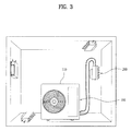
- FIG. 3 is a view illustrating various installation positions of the distribution device of the air conditioner of FIG. 1 ;
- FIGs. 4 and 5 are perspective views illustrating a portion of the air conditioner of FIG. 1 ;
- FIGs. 6 to 14 are perspective views illustrating a distribution device of the air conditioner of FIG. 1 .
- An air conditioner is a cooling/heating system that cools a room by repeatedly performing a series of operations, including suctioning indoor air, performing heat exchange between a low-temperature refrigerant and the suctioned indoor air, and discharging the heat-exchanged air into the room, or heats a room by repeatedly performing the above operations for cooling in reverse.
- the air conditioner has a series of cycles constituted by a compressor, an outdoor heat exchanger, an expansion valve, and an indoor heat exchanger.
- Recent air conditioners have added various functions, such as an air fiction function for suctioning contaminated indoor air, filtering the suctioned air, and resupplying the filtered air into an air conditioning space, and a dehumidification function for dehumidifying humid air while circulating the humid air and resupplying the dehumidified air into the air conditioning space, in addition to cooling and heating of the air conditioning space.
- Air conditioners generally may be classified into separate air conditioners, in which each of an outdoor unit or device and an indoor unit or device are mounted in a separate manner, and integrated air conditioners, in which each of an outdoor unit or device and an indoor unit or device are mounted in an integrated manner.
- multi type air conditioners in which each of a plurality of indoor units or devices are connected to a single outdoor unit or device so as to commonly use the outdoor unit or device, have been also used.
- the multi type air conditioner has an effect equivalent to that obtained by installing a plurality of conventional separate air conditioners, each of which includes a single outdoor device and a single indoor device. Users may add indoor devices, as needed.
- An outdoor device of an air conditioner may include an outdoor heat exchanger that performs heat exchange between a refrigerant and air in an air conditioning space, n which the outdoor device is installed, and a compressor.
- refrigerant circulated through respective indoor devices may be collected in the same outdoor device, and the collected refrigerant may be distributed to the respective indoor devices through a compression process and a condensing process (when a room is cooled), which may be repeatedly performed.
- Multi type air conditioners each of which includes a plurality of indoor devices and a single outdoor device connected to the respective indoor devices, have an advantage in that it is possible to reduce the number of outdoor devices.
- piping is complicated because the respective indoor devices are individually connected to the outdoor device.
- a length of pipes may be increased in proportion to the number of the outdoor devices if a distance between the outdoor devices and an air conditioning space increases.
- an outdoor device of a multi type air conditioner may suction air from a front or rear of the outdoor device and discharge heat-exchanged air to the rear or front of the outdoor device. Consequently, an installation direction of the outdoor device may be specified in an installation space of the outdoor device.
- the outdoor device may be provided at a side thereof with indoor device-side connection parts, to which a refrigerant pipe connected to the indoor devices may be connected.
- a plurality of pipes may be bypassed to the front or rear of the outdoor device depending upon the installation direction of the outdoor device and a position of an air conditioning space, such that the pipes may be connected to the respective indoor device-side connection parts.
- the refrigerant pipes detour around the outdoor device
- the refrigerant pipes which may be connected between all of the indoor devices and the outdoor device, may be bent, thereby increasing flow resistance of the refrigerant in all of the refrigerant pipes, which may decrease energy efficiency of the air conditioner.
- An air conditioner in accordance with an embodiment may include an outdoor device including a main controller, a compressor, an outdoor heat exchanger, and an air blower fan, a plurality of indoor devices, and a distribution device connected to the respective indoor devices and the outdoor device and including a cover assembly that surrounds a liquid refrigerant pipe assembly and a vapor refrigerant pipe assembly, respectively, provided with electronic expansion valves mounted thereon and a sub controller that communicates with the main controller.
- the electronic expansion valves may be selectively adjusted by the main controller of the outdoor device or the sub controller of the distribution device.
- FIG. 1 is a schematic view of an air conditioner in accordance with an embodiment, including a plurality of indoor devices, an outdoor device, and a distribution device.
- Figure 2 is a block diagram of the air conditioner of FIG. 1 .
- FIG. 3 is a view illustrating various installation positions of the distribution device of the air conditioner of FIG. 1 .
- the air conditioner 1 may include at least two indoor devices 300A to 300E, an outdoor devic 100, which may include a compressor 170 and an outdoor device case 110, and a distribution device 200, which may include at least two indoor device-side connection parts, respectively, connected to the indoor devices 300A to 300E, an outdoor device-side connection part connected to the outdoor device 100, and a cover assembly.
- the distribution device 200 may be detachably mounted in a mounting space within the outdoor device case 110. With reference to FIG. 3 , the distribution device 200 may be installed at various positions according to positions of air conditioning spaces in which indoor devices (not shown) of the air conditioner are installed, and an installation direction of the outdoor device 100 of the air conditioner.
- the outdoor device 100 may suck in outdoor air, perform heat-exchange with the outdoor air, and then discharge the heat-exchanged air in a specific direction (in a direction from a heat exchanger 140 to an air blower fan 103). If all indoor devices 300A to 300E are connected to the outdoor device 100 by respective pipes, the aesthetics of an installation space in which the outdoor device 100 is installed may be spoiled. Therefore, as shown in FIG. 1 , if the outdoor device 100 and the respective indoor devices 300A to 300E are connected via the distribution device 200, a length of the pipes may be reduced in proportion to a distance between the outdoor device 100 and the distribution device 200.
- the outdoor device may be provided with indoor device-side connection parts connected to the respective indoor devices, or may be provided with a distribution device-side connection part connected to a separate distribution device as a precondition to use of the distribution device, and thus, the conventional multi type air conditioner cannot satisfy various user requirements.
- the air conditioner in accordance with an embodiment may include the distribution device 200 detachably mounted in the outdoor device 100, or embedded in the outdoor device 100.
- the outdoor device 100 may be directly connected to the respective indoor devices 300A to 300E via transmitting/receiving cables that transmit/receive a control signal, and a sub controller 400 of the distribution device 200 and the outdoor device 100 may be connected. That is, the distribution device 200 and the respective indoor devices may not be connected via separate communication cables that transmit/receive a control signal.
- One advantage of the distribution device 200 of the air conditioner in accordance with an embodiment is to minimize a length of refrigerant pipes connecting the outdoor device 100 and the distribution device 200, so as to reduce installation costs of the air conditioner and to improve aesthetic effects. Therefore, a shorter length of the refrigerant pipes may be favorable. However, the installation costs of the transmitting/receiving cables that transmit/receive the control signal may not be increased significantly due to the different lengths of the refrigerant pipes, and thus, minimization of connection parts of the transmitting/receiving cables may be achieved.
- the controller has a large volume, and thus, a space in the distribution device occupied by the controller is large. Therefore, in the conventional multi air conditioner, the size of the distribution device is large, and thus, efficiency in use of the distribution device may be reduced. Further, if the distribution device is installed outdoors, a structure that shields rainwater or moisture must also be considered or included and thus, an overall size of the distribution device may be further increased.
- sub controller 400 mounted on the distribution device 200 may be provided in order to control electronic expansion valves or valves provided in the distribution device 200, separately from the main controller provided in the outdoor device 100.
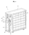
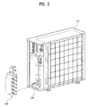
- FIGs. 4 and 5 are perspective views illustrating a portion of the air conditioner of FIG. 1 .
- the outdoor device 100 may include the outdoor device case 110 forming an external appearance of the outdoor device 100, a compressor 170, and an outdoor heat exchanger 140, respectively, mounted in the outdoor devie case 110. Further, a refrigerant pipe connection part 150 that respectively connects the compressor 170, the outdoor heat exchanger 140, and an outdoor device-side connection part 250 of the distribution device 200 may be provided in the outdoor device case 110. The refrigerant pipe connection part 150 may be provided above the distribution device 200.
- a mounting space to mount the distribution device 200 may be provided at or in an area in which a flow of sucked outdoor air having passed through the outdoor heat exchanger 140 may not be disturbed.
- the mounting space may be a space near any one of both side surfaces of an inner space of the outdoor device case 110. Further, the mounting space may be a space near the compressor 170.
- the compressor 170 provided in the outdoor device 100 may be located at a position in which the flow of the outdoor air is not disturbed.
- the position of the compressor 170 and the outdoor heat exchanger 140 in the inner space of the outdoor device case 110, at which the flow of the outdoor air is not disturbed, may be an edge of a side surface of the outdoor device case 110, and in order to form a plurality of indoor device-side connection parts 270 on the distribution device 200, the distribution device 200 may have a predetermined and sufficient length.
- the mounting space of the distribution device 200 may be located near a side surface of the outdoor device case 110 within the inner space of the outdoor device case 110.
- an opening may be formed through the outdoor device case 110 near the mounting space, as shown in FIG.4 .
- the indoor device-side connection parts 270 of the distribution device 200 may be exposed to the outside through the opening.
- the air conditioner may further include a cover member (not shown) that selectively opens and closes the opening of the outdoor device case 110.
- the outdoor device-side connection part 250 of the distribution device 200 to be connected to the inside of the outdoor device 100 may be connected to the compressor 170 or the outdoor heat exchanger 140, while minimizing a distance of a refrigerant pipe connected to the compressor 170 or the outdoor heat exchanger 140.
- the outdoor device-side connection part 250 of the distribution device 200 and the pipe connection part 150 of the outdoor device 100 may be connected above the distribution device 200.
- the pipe connection part 150 may include a high pressure socket 151 and a low pressure socket 155, respectively, connected to a liquid refrigerant pipe assembly and a vapor refrigerant pipe assembly via the outdoor device-side connection part 250.
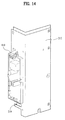
- FIGs. 6 to 14 are perspective views illustrating the distribution device 200 of the air conditioner in accordance with an embodiment.
- FIG. 6 illustrates the distribution device 200, and a mounting member 120 provided in the outdoor device case 110.
- the distribution device 200 may be detachably mounted in the outdoor device case 110, and the mounting member 120, which may support the distribution device 200, may be provided in the mounting space of the distribution device 200 in the outdoor device case 110.
- the mounting member 120 may have various structures capable of supporting the distribution device 200 without a separate fastening member.
- the mounting member 120 may be a structure that supports a lower surface of the distribution device 200 and lower regions of two or more side surfaces of the distribution device 200.
- the mounting member 120 may include a horizontal part 121, on which the lower surface of the distribution device 200 may be seated, and a plurality of vertical parts 122, respectively, that extend vertically from longitudinal ends of the horizontal part 121.
- the distribution device 200 may be detachably mounted in a space formed by the horizontal part 121 and the plurality of vertical parts 122.
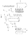
- FIG. 7 is an exploded perspective view of the distribution device 200 of the air conditioner in accordance with an embodiment.
- FIG. 8 is a perspective view of the distribution device 200 in a state in which respective constituent members are connected.
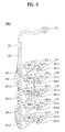
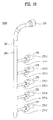
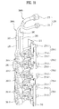
- FIGs. 9 to 11 are perspective views illustrating respective refrigerant pipe assemblies of the distribution device 200.
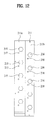
- FIGs. 12 and 13 are front and perspective views illustrating a cover assembly of the distribution device 200, and
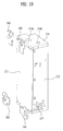
- FIG. 14 is a perspective view illustrating a connection state of the outdoor device, the indoor devices, and the distribution device of the air conditioner in accordance with an embodiment.
- the distribution device 200 may be disposed in the mounting space within the outdoor device case 110, as described above, and may include a liquid refrigerant pipe assembly 200A and a vapor refrigerant pipe assembly 200B, respectively, connected to the indoor devices 300A to 300E and the outdoor device 100, and a cover assembly 210 that surrounds the liquid refrigerant pipe assembly 200A and the vapor refrigerant pipe assembly 200B.
- the cover assembly 210 may form an external appearance of the distribution device 200, and the respective refrigerant pipe assemblies 200A and 200B may be received in the cover assembly 210.
- the cover assembly 210 may include a first cover 211 that exposes the indoor device-side connection parts 270 (270-1-270-5) of the respective refrigerant pipe assemblies 200A and 200B to the outside.
- the first cover 211 may include a first region 211a and a second region 211b disposed so as to be partially exposed to the outside through the opening of the outdoor device case 110, and provided with first through holes 215 and second through holes 216 to, respectively, expose to the outside the indoor device-side connection parts 270 (270-1-270-5) of the liquid and vapor refrigerant pipe assemblies 200A and 200B.
- the first cover 211 may be configured such that the first region 211a and the second region 211b may be disposed in a stepped manner. Thereby, the first region 211a may protrude to the outside further in comparison with the second region 211b, or the second region 211b may protrude to the outside further in comparison with the first region 211a. Because the indoor device-side connection parts 270 (270-1-270-5) of the distribution device 200 are exposed to the outside through the opening of the outdoor device case 110, a worker may perform refrigerant connecting work with the indoor devices through the opening.
- indoor device-side high pressure sockets 271-1-271-5 of the liquid refrigerant pipe assembly 200A and indoor device-side low pressure sockets 275-1-275-5 of the vapor refrigerant pipe assembly 200B may be exposed to the outside through the respective stepped regions 211a and 211b of the first cover 211, the worker may easily perform the connecting work without interference with the neighboring indoor device-side connection parts 270.
- the first cover 211 may be divided into the first region 211a and the second region 211b in a widthwise direction, and the plurality of first through holes 215 and the plurality of second through holes 216 may be formed through the respective regions 211a and 211b in a lengthwise direction.
- Each second through hole 216 may be located between two neighboring two first through holes 215.
- the cover assembly 210 may further include a plurality of covers connected to the first cover 211 and assembled with each other, so as to form an inner space to receive the respective refrigerant pipe assemblies 200A and 200B.
- the cover assembly 210 may further include a second cover 212 connected to the first cover 211 and forming at least two side surfaces, a third cover 213, respectively, connected to the first and second covers 211 and 212 and forming another side surface and a lower surface, and a fourth cover 214, respectively, connected to the first, second, and third covers 211, 212, and 213 and forming an upper surface.
- any of the various covers, and in particular, the fourth cover 214 may be formed by injection molding, so as to increase water-tightness and air-tightness.
- First and second insertion holes 214a and 214b to expose the outdoor device-side connection part 250 (251 and 255) of the respective refrigerant pipe assemblies 200A and 200B to the outside may be formed through the fourth cover 214.
- the distribution device 200 in accordance with an embodiment may include the cover assembly 210, which may be formed in a square column, and the indoor device-side connection parts 270, which may be connected to the plurality of indoor devices 300A to 300E, may be provided on one of the side surfaces of the cover assembly 210.
- This embodiment illustrates the distribution device 200 provided with five indoor device-side connection parts 270 (270-1, 270-2, 270-3, 270-4, and 270-5) so as to be connected to five indoor devices 300A to 300E.
- the number of the indoor device-side connection parts 270 may be varied according to a capacity of the compressor. If the capacity of the compressor is increased, the number of the indoor device-side connection parts 270 may be increased.
- the sub controller 400 which may control electronic expansion valves provided in the distribution device 200, may be mounted on one side surface of the second cover 212 of the cover assembly 210 opposite to the first cover 211 exposing the indoor device-side connection parts 270.
- the sub controller 400 may include a substrate 410, on which a communication device for communication with the main controller (not shown) of the outdoor device 100, may be mounted, and a housing 420 that surrounds the substrate 410.
- the sub controller 400 may be provided to control the electronic expansion valves or valves provided in the distribution device 200, separately from the main controller provided in the outdoor device 100.
- An electronic circuit that controls the electronic expansion valves or the valves, which may be provided in the distribution device 200 and adjust a flow of the refrigerant or decompress (or expand) the refrigerant, may be mounted on the substrate 410 within the housing 420. Therefore, the substrate 410 provided within the housing 420 may be configured so as to control only the electronic expansion valves in the distribution device 200.
- the housing 420 of the sub controller 400 may be additionally mounted on the cover assembly 210.
- the housing 420 may be detachably mounted on the outer surface of the cover assembly 210.
- an entrance hole 219 to pass cables to connect the electronic expansion valves provided in the distribution device 200 to the sub controller 400 may be provided on the cover assembly 210 and the housing 420 at corresponding positions.
- the entrance hole 219 may be formed on any one side surface of the cover assembly 210, in order to provide the distribution device 200 with an aesthetically pleasing external appearance and to shorten a distance of the cables.
- the entrance hole 219 may be formed on the second cover 212 of the cover assembly 210, on which the housing 420 may be mounted.
- the entrance hole 219 may be a slit, a partial region of which is open.
- the cables connected to the electronic expansion valves in the distribution device 200 may be disposed in the slit, and then, the second cover 212 may be connected to the third cover 213, thereby assembling the cover assembly 200.
- a sealing member (not shown) may be provided between the cover assembly 210 and the housing 420.
- the sealing member may prevent the introduction of foreign substances, such as rainwater or moisture, therein, although the distribution device 200 is installed outdoors.
- a main pipe 220 of the liquid refrigerant pipe assembly 200A of the distribution device 200 and a main pipe 280 of the vapor refrigerant pipe assembly 200B of the distribution device 200 may be provided with at least one expansion part 222 and at least one expansion part 282.
- the pipe expansion parts 222 and 282 may be obtained by expanding inner diameters of the main pipe 220 of the liquid refrigerant pipe assembly 200A and the main pipe 280 of the vapor refrigerant pipe assembly 200B, extended to the outside through the upper surface of the cover assembly 210.
- the pipe expansion parts 222 and 282, each of which may have an expanded inner diameter, may be, for example, cut, and then the other refrigerant pipes connected thereto.
- the pipe expansion parts 222 and 282 may be provided on portions of the main pipe 220 of the liquid refrigerant pipe assembly 200A and the main pipe 280 of the vapor refrigerant pipe assembly 200B, which may extend vertically so as to be located above the cover assembly 210 of the distribution device 20.
- the pipe connection part 150 of the outdoor device 100 may be disposed in the horizontal direction, and the main pipe 220 of the liquid refrigerant pipe assembly 200A and the main pipe 280 of the vapor refrigerant pipe assembly 200B may be bent, such that the outdoor device-side connection part 250 provided at ends of the main pipe 220 of the liquid refrigerant pipe assembly 200A and the main pipe 280 of the vapor refrigerant pipe assembly 200B may be disposed in a direction corresponding to a disposition direction of the pipe connection part 150.
- connection structure may be obtained only if the distribution device 200 is mounted within the outdoor device 100. On the other hand, if the distribution device 200 is mounted at a separate installation place other than the inside of the outdoor device 100, the outdoor device-side connection part 250 of the distribution device 200 does not need to have the bent structure, as shown in FIG. 6 .
- welding of pipes having similar diameters under a condition that no pipe expansion part is formed may cause a lowering of work efficiency or deterioration of reliability of connection between the pipes, compared with welding of pipes under the condition that one pipe is inserted into the other pipe.
- FIGs. 9 and 10 illustrate inner pipes of the distribution device 200 of the air conditioner in accordance with an embodiment.
- FIG. 9 illustrates a pipe structure of the liquid refrigerant pipe assembly 200A, which distributes or decompresses (expands) the refrigerant supplied from the outdoor device
- FIG. 10 illustrates a pipe structure of the vapor refrigerant pipe assembly 200B.
- a set of pipes for example, the liquid refrigerant pipe assembly 200A, which distributes or decompresses (expands) the refrigerant supplied from the outdoor device 100, and then, supplies the distributed or decompressed refrigerant to the plurality of indoor devices 300A to 300F during the cooling cycle, may be referred to as a high pressure part 200A
- a set of pipes, for example, the vapor refrigerant pipe assembly 200B, which collects the refrigerant from the plurality of indoor devices 300A to 300F and then, supplies the collected refrigerant to the outdoor device 100 during the cooling cycle may be referred to as a low pressure part 200B.
- the high pressure part 200A may be a main refrigerant assembly.
- An outdoor device-side high pressure socket 251 of the above-described outdoor device-side connection part 250 may be provided at one end of the main pipe 220 of the high pressure part 200A, and may be connected to the high pressure socket 151 of the pipe connection part 150 at a side of the compressor 170.
- a distributor 240 may be provided at the other end of the main pipe 220.
- the distributor 240 may distribute the refrigerant to first to fifth electronic expansion valves 260-1, 260-2, 260-3, 260-4, and 260-5 that decompress or expand the refrigerant supplied to the respective indoor device-side connection parts 270-1, 270-2, 270-3, 270-4, and 270-5.
- First to fifth liquid branch pipes 241-1, 241-2, 241-3, 241-4, and 241-5 that guide the refrigerant to the first to fifth electronic expansion valves 260-1, 260-2, 260-3, 260-4, and 260-5 may be provided at the distributor 240.
- the first to fifth liquid branch pipes 241-1, 241-2, 241-3, 241-4, and 241-5 may be branched from the distributor 240, and may be connected to the respective electronic expansion valves 260-1, 260-2, 260-3, 260-4, and 260-5.
- the refrigerant supplied through the first to fifth liquid branch pipes 241-1, 241-2, 241-3, 241-4, and 241-5 may be, respectively, decompressed or expanded by the first to fifth electronic expansion valves 260-1, 260-2, 260-3, 260-4, and 260-5, and then, may be, respectively, supplied to the first to fifth indoor devices 300A, 300B, 300C, 300D, and 300E provided in respective air conditioning spaces through the first to fifth indoor device-side high pressure sockets 271-1, 271-2, 271-3, 271-4, and 271-5 of the indoor device-side connection parts 270.
- the first to fifth indoor device-side high pressure sockets 271-1, 271-2, 271-3, 271-4, and 271-5 may be, respectively, connected to the first to fifth electronic expansion valves 260-1, 260-2, 260-3, 260-4, and 260-5 by first to fifth liquid connection pipes 265-1, 265-2, 265-3, 265-4, and 265-5.
- the first to fifth electronic expansion valves 260-1, 260-2, 260-3, 260-4, and 260-5 may be, respectively, provided with first to fifth communication line connection parts 261-1, 261-2, 261-3, 261-4, and 261-5.
- the control signal supplied from the main controller provided in the outdoor device may be transmitted to the first to fifth electronic expansion valves 260-1, 260-2, 260-3, 260-4, and 260-5 through the first to fifth communication line connection parts 261-1, 261-2, 261-3, 261-4, and 261-5, and then, may control the first to fifth electronic expansion valves 260-1, 260-2, 260-3, 260-4, and 260-5, thereby adjusting flow amounts of the refrigerant and expanding (decompressing) the refrigerant.
- the vapor refrigerant pipe assembly 200B may include first to fifth vapor branch pipes 277-1, 277-2, 277-3, 277-4, and 277-5, which may be branched from the main pipe 280 at a predetermined interval toward the indoor device-side low pressure sockets 275-1, 275-2, 275-3, 275-4, and 275-5 of the indoor device-side connection parts 270-1, 270-2, 270-3, 270-4, and 270-5.
- the main pipe 280 of the low pressure part 200B as shown in FIG.
- a separate distributor need not be provided on the main pipe 280.
- a distributor connecting the first to fifth vapor branch pipes 277-1, 277-2, 277-3, 277-4, and 277-5 and the main pipe 280 may be provided in consideration of a heating cycle.
- FIG. 11 illustrates an assembled state of the respective refrigerant pipe assemblies 200A and 200B in the distribution device with the first cover 211 in the air conditioner in accordance with an embodiment.
- the respective refrigerant pipe assemblies 200A and 200B may include the main pipes 220 and 280 having the low pressure socket 251 and the high pressure socket 255 of the outdoor device-side connection part 250, and the plurality of branch pipes branched from the main pipes 220 and 280 and, respectively, provided with fastening parts 279 and 278 to be fastened to the first cover 211.
- a plurality of fastening holes 217 and a plurality of fastening holes 218 to be fastened to the fastening parts 279 and 278 of the respective branch pipes may be formed through the first cover 211.
- the respective through holes 215 and 216 of the first cover 211 may be formed in a polygonal shape, and the respective branch pipes disposed in the through holes 215 and 216 may have a cross-section formed in a polygonal shape corresponding to the polygonal shape of the respective through holes 215 and 216.
- each branch pipe may maintain a fitted state thereof in the respective through holes 215 and 216, and may not move during the connecting process.
- the fastening part 278 or 279 of each branch pipe may be connected to the first cover 211 by one connector.
- the connector may be, for example, a screw. That is, each branch pipe may be connected to the first cover 211 by a screw, thereby reducing manpower and reducing the number of fastening components.
- the distribution device 200 may further include a plurality of mounting brackets 500 fastened to the cover assembly 210.
- the mounting brackets 500 may serve to fix the distribution device 200 to an installation wall at the outside of the outdoor device 100.
- the mounting brackets 500 may be fastened, for example, to one of the second cover 212 and the third cover 213. In this embodiment, the mounting brackets 500 may be fastened into fastening holes to fasten the second cover 212 and the third cover 213 to each other.
- an air conditioner in accordance with embodiments disclosed herein may minimize lengths of pipes connecting a plurality of indoor devices and an outdoor device, facilitate connection of respective refrigerant pipes to a distribution device, and reduce manpower and a number of fastening components.
- the air conditioner in accordance with embodiments disclosed herein may not require a separate cable to transmit/receive a control signal between the plurality of indoor devices and the distribution device.
- the air conditioner in accordance with embodiments disclosed herein may facilitate an assembly process of the distribution device, and reduce manpower and the number of assembly components.
- Embodiments disclosed herein provide an air conditioner which may minimize lengths of pipes connecting a plurality of indoor devices and an outdoor device, facilitate connection of respective refrigerant pipes to a distribution device, and reduce manpower and a number of fastening components.
- Embodiments disclosed herein further provide an air conditioner which may not require a separate cable to transmit/receive a control signal between the plurality of indoor devices and the distribution device.
- Embodiments disclosed herein additionally provide an air conditioner that may facilitate an assembly process of a distribution device, and reduce manpower and a number of assembly components.
- an air conditioner may include an outdoor unit or device including a main controller, an outdoor heat exchanger, and a compressor; a plurality of indoor units or devices, each of which may include an indoor heat exchanger; and a distribution unit or device connected to the outdoor unit and the plurality of indoor units, and including liquid and vapor refrigerant pipe assemblies provided with electronic expansion valves mounted thereon, a cover assembly that surrounds the respective refrigerant pipe assemblies, and a sub controller communicable with the main controller.
- the electronic expansion valves may be controlled by the main controller or the sub controller, selectively.
- Embodiments disclosed herein further provide an air conditioner that may include an outdoor unit or device including an outdoor unit or device case, provided with an opening formed at one side, in which a main controller, an outdoor heat exchanger, and a compressor may be disposed; a plurality of indoor units or devices, each of which may include an indoor heat exchanger; and a distribution unit or device detachably mounted in the outdoor unit, and including liquid and vapor refrigerant pipe assemblies provided with electronic expansion valves mounted thereon, a cover assembly that surrounds the respective refrigerant pipe assemblies, and a sub controller communicable with the main controller.
- the electronic expansion valves may be controlled by the main controller or the sub controller, selectively.
- Embodiments disclosed herein additionally provide an air conditioner that may include a plurality of indoor units or devices; an outdoor unit or device including a compressor that compresses a refrigerant and a main controller that adjusts amounts of the refrigerant discharged to the plurality of indoor units; and a distribution unit or device including a sub controller that distributes the refrigerant discharged from the outdoor unit to the plurality of indoor units and then adjusts amounts of the distributed refrigerant The amounts of the refrigerant distributed through the distribution unit may be adjusted by the main controller or the sub controller, selectively.
- any reference in this specification to "one embodiment,” “an embodiment,” “example embodiment,” etc. means that a particular feature, structure, or characteristic described in connection with the embodiment is included in at least one embodiment of the invention.
- the appearances of such phrases in various places in the specification are not necessarily all referring to the same embodiment.
Landscapes
- Engineering & Computer Science (AREA)
- Mechanical Engineering (AREA)
- General Engineering & Computer Science (AREA)
- Chemical & Material Sciences (AREA)
- Combustion & Propulsion (AREA)
- Physics & Mathematics (AREA)
- Thermal Sciences (AREA)
- Other Air-Conditioning Systems (AREA)
- Compression-Type Refrigeration Machines With Reversible Cycles (AREA)
Applications Claiming Priority (1)
| Application Number | Priority Date | Filing Date | Title |
|---|---|---|---|
| KR1020100021708A KR101727034B1 (ko) | 2010-03-11 | 2010-03-11 | 공기조화장치 |
Publications (2)
| Publication Number | Publication Date |
|---|---|
| EP2365254A2 true EP2365254A2 (fr) | 2011-09-14 |
| EP2365254A3 EP2365254A3 (fr) | 2014-12-17 |
Family
ID=44278794
Family Applications (1)
| Application Number | Title | Priority Date | Filing Date |
|---|---|---|---|
| EP11157169.1A Ceased EP2365254A3 (fr) | 2010-03-11 | 2011-03-07 | Climatiseur |
Country Status (4)
| Country | Link |
|---|---|
| US (1) | US20110219799A1 (fr) |
| EP (1) | EP2365254A3 (fr) |
| KR (1) | KR101727034B1 (fr) |
| CN (1) | CN102192557B (fr) |
Cited By (4)
| Publication number | Priority date | Publication date | Assignee | Title |
|---|---|---|---|---|
| US20160377332A1 (en) * | 2013-12-11 | 2016-12-29 | Daikin Industries, Ltd. | Refrigerant channel switching unit |
| US9618218B2 (en) | 2012-02-09 | 2017-04-11 | Johnson Controls-Hitachi Air Conditioning Technology (Hong Kong) Limited | Air conditioner |
| WO2018012036A1 (fr) * | 2016-07-11 | 2018-01-18 | 日立ジョンソンコントロールズ空調株式会社 | Unité de commutation de passage d'écoulement de réfrigérant et climatiseur pourvu de celle-ci |
| WO2018012045A1 (fr) * | 2016-07-11 | 2018-01-18 | 日立ジョンソンコントロールズ空調株式会社 | Unité de commutation et de collecte de réfrigérant |
Families Citing this family (17)
| Publication number | Priority date | Publication date | Assignee | Title |
|---|---|---|---|---|
| JP6197988B2 (ja) * | 2013-03-28 | 2017-09-20 | 株式会社富士通ゼネラル | 空気調和機の冷媒分岐ユニットのカバー構造体 |
| JP6146693B2 (ja) * | 2013-03-28 | 2017-06-14 | 株式会社富士通ゼネラル | 空気調和機の冷媒分岐ユニットのカバー構造体 |
| JP6164459B2 (ja) * | 2013-03-28 | 2017-07-19 | 株式会社富士通ゼネラル | 空気調和機の冷媒分岐ユニットのカバー構造体 |
| CN104422042B (zh) * | 2013-08-19 | 2019-04-26 | 珠海格力电器股份有限公司 | 一种空调连接管走管的方法和装置 |
| CN104424364B (zh) * | 2013-08-19 | 2018-10-30 | 珠海格力电器股份有限公司 | 一种空调连接管自动走管的方法和装置 |
| JP6116491B2 (ja) * | 2014-01-16 | 2017-04-19 | 三菱電機株式会社 | 分岐装置 |
| JP5884855B2 (ja) * | 2014-05-30 | 2016-03-15 | ダイキン工業株式会社 | 冷媒流路切換ユニット |
| JP6264249B2 (ja) * | 2014-09-26 | 2018-01-24 | 株式会社富士通ゼネラル | 空気調和機の室外機 |
| JP6547956B2 (ja) * | 2015-12-28 | 2019-07-24 | 株式会社富士通ゼネラル | 空気調和機の室外機 |
| JP6728871B2 (ja) * | 2016-03-29 | 2020-07-22 | 株式会社富士通ゼネラル | 空気調和装置の室外機 |
| JP6696261B2 (ja) * | 2016-03-29 | 2020-05-20 | 株式会社富士通ゼネラル | 空気調和装置の室外機 |
| JP2017180888A (ja) * | 2016-03-29 | 2017-10-05 | 株式会社富士通ゼネラル | 空気調和装置の室外機 |
| JP2017180887A (ja) * | 2016-03-29 | 2017-10-05 | 株式会社富士通ゼネラル | 空気調和装置の室外機 |
| CN107036186A (zh) * | 2017-04-18 | 2017-08-11 | 海信(山东)空调有限公司 | 一种家用空调器系统 |
| JP6945515B2 (ja) * | 2018-11-06 | 2021-10-06 | 株式会社鷺宮製作所 | 温度式膨張弁ユニット、および、それを備える冷凍サイクルシステム |
| KR102596984B1 (ko) * | 2019-01-31 | 2023-11-02 | 삼성전자주식회사 | 공기조화기의 실외기 |
| CN117120779B (zh) * | 2021-03-31 | 2024-04-12 | 大金工业株式会社 | 空调机 |
Family Cites Families (15)
| Publication number | Priority date | Publication date | Assignee | Title |
|---|---|---|---|---|
| US4257239A (en) * | 1979-01-05 | 1981-03-24 | Partin James R | Earth coil heating and cooling system |
| JPS6334459A (ja) * | 1986-07-29 | 1988-02-15 | 株式会社東芝 | 空気調和機 |
| JP3655681B2 (ja) * | 1995-06-23 | 2005-06-02 | 三菱電機株式会社 | 冷媒循環システム |
| TW339401B (en) * | 1997-02-28 | 1998-09-01 | Sanyo Electric Co | Coolant branching device for an air conditioner |
| JP3175676B2 (ja) * | 1997-12-05 | 2001-06-11 | ダイキン工業株式会社 | 冷媒分岐ユニット |
| JP2002013763A (ja) * | 2000-04-24 | 2002-01-18 | Daikin Ind Ltd | 空気調和機の分岐ユニット |
| KR100371587B1 (ko) * | 2000-12-15 | 2003-02-11 | 한국과학기술연구원 | Can통신망을 이용한 유연한 소형의 전동기 제어장치 |
| KR20050019677A (ko) * | 2003-08-20 | 2005-03-03 | 캐리어엘지 유한회사 | 분리형 냉동장치가 구비된 냉동/냉장고 |
| CN2703986Y (zh) * | 2003-12-26 | 2005-06-08 | 上海日立电器有限公司 | 家用中央空调机组的制冷剂流量分配装置 |
| US7400239B2 (en) * | 2004-09-03 | 2008-07-15 | Simply Automated, Incorporated | Universal control apparatus and methods |
| JP3885817B2 (ja) * | 2005-04-19 | 2007-02-28 | ダイキン工業株式会社 | 分岐冷媒中継ユニットおよびその製造方法 |
| JP4721943B2 (ja) * | 2006-04-04 | 2011-07-13 | 三洋電機株式会社 | 空気調和装置の室外機 |
| JP4904908B2 (ja) * | 2006-04-28 | 2012-03-28 | ダイキン工業株式会社 | 空気調和装置 |
| US20090211288A1 (en) * | 2008-02-25 | 2009-08-27 | Carrier Corporation | Combination microchannel condenser and radiator mounting arrangement |
| JP2009229012A (ja) * | 2008-03-24 | 2009-10-08 | Daikin Ind Ltd | 冷凍装置 |
-
2010
- 2010-03-11 KR KR1020100021708A patent/KR101727034B1/ko active IP Right Grant
-
2011
- 2011-01-28 CN CN201110035626.2A patent/CN102192557B/zh not_active Expired - Fee Related
- 2011-03-07 EP EP11157169.1A patent/EP2365254A3/fr not_active Ceased
- 2011-03-10 US US13/044,817 patent/US20110219799A1/en not_active Abandoned
Non-Patent Citations (1)
| Title |
|---|
| None |
Cited By (7)
| Publication number | Priority date | Publication date | Assignee | Title |
|---|---|---|---|---|
| US9618218B2 (en) | 2012-02-09 | 2017-04-11 | Johnson Controls-Hitachi Air Conditioning Technology (Hong Kong) Limited | Air conditioner |
| US20160377332A1 (en) * | 2013-12-11 | 2016-12-29 | Daikin Industries, Ltd. | Refrigerant channel switching unit |
| US9651283B2 (en) * | 2013-12-11 | 2017-05-16 | Daikin Industries, Ltd. | Refrigerant channel switching unit |
| WO2018012036A1 (fr) * | 2016-07-11 | 2018-01-18 | 日立ジョンソンコントロールズ空調株式会社 | Unité de commutation de passage d'écoulement de réfrigérant et climatiseur pourvu de celle-ci |
| WO2018012045A1 (fr) * | 2016-07-11 | 2018-01-18 | 日立ジョンソンコントロールズ空調株式会社 | Unité de commutation et de collecte de réfrigérant |
| JP2018009708A (ja) * | 2016-07-11 | 2018-01-18 | 日立ジョンソンコントロールズ空調株式会社 | 冷媒切替集合ユニット |
| US10557654B2 (en) | 2016-07-11 | 2020-02-11 | Hitachi-Johnson Controls Air Conditioning, Inc. | Collective device for switching refrigerant flow |
Also Published As
| Publication number | Publication date |
|---|---|
| CN102192557A (zh) | 2011-09-21 |
| EP2365254A3 (fr) | 2014-12-17 |
| US20110219799A1 (en) | 2011-09-15 |
| KR20110102616A (ko) | 2011-09-19 |
| CN102192557B (zh) | 2014-06-04 |
| KR101727034B1 (ko) | 2017-04-14 |
Similar Documents
| Publication | Publication Date | Title |
|---|---|---|
| EP2365254A2 (fr) | Climatiseur | |
| EP2365255A2 (fr) | Appareil de climatisation | |
| EP2365253B1 (fr) | Dispositif de climatisation incluant une unité externe et unité de distribution | |
| EP2815187B1 (fr) | Appareil de conditionnement d'air | |
| CN108626798B (zh) | 空气调节器 | |
| EP2037187A2 (fr) | Unité extérieure pour climatiseur | |
| US8826689B2 (en) | Air conditioner and outdoor unit | |
| EP1659343B1 (fr) | Unité d'intérieur d'un dispositif de conditionnement d'air | |
| EP3903043B1 (fr) | Unité extérieure de climatiseur | |
| KR20110102615A (ko) | 공기조화장치 | |
| US7007498B2 (en) | HVAC cabinet with configurable duct connections | |
| CN217057716U (zh) | 空调室内机 | |
| JP7037364B2 (ja) | 熱源ユニットを組み立てるためのセット及び方法 | |
| EP3385627B1 (fr) | Unité extérieure | |
| KR101662079B1 (ko) | 공기조화장치 | |
| KR20100097296A (ko) | 공기조화장치 | |
| CN217004695U (zh) | 一种空调器及空调系统 | |
| CN219036887U (zh) | 移动式空调器 | |
| CN217109780U (zh) | 空调室内机 | |
| CN218120174U (zh) | 底座、柜式空调室内机及空调器 | |
| CN110285500B (zh) | 便于安装的空调 | |
| KR100565513B1 (ko) | 멀티형 공기조화기의 밸브서포트 | |
| US20190078816A1 (en) | Convertible case horizontal refrigeration coil | |
| KR20100097309A (ko) | 공기조화장치 및 실외기 | |
| KR20240037033A (ko) | 창문형 공기 조화기 및 창문형 공기 조화기의 설치 방법 |
Legal Events
| Date | Code | Title | Description |
|---|---|---|---|
| PUAI | Public reference made under article 153(3) epc to a published international application that has entered the european phase |
Free format text: ORIGINAL CODE: 0009012 |
|
| 17P | Request for examination filed |
Effective date: 20110406 |
|
| AK | Designated contracting states |
Kind code of ref document: A2 Designated state(s): AL AT BE BG CH CY CZ DE DK EE ES FI FR GB GR HR HU IE IS IT LI LT LU LV MC MK MT NL NO PL PT RO RS SE SI SK SM TR |
|
| AX | Request for extension of the european patent |
Extension state: BA ME |
|
| PUAL | Search report despatched |
Free format text: ORIGINAL CODE: 0009013 |
|
| AK | Designated contracting states |
Kind code of ref document: A3 Designated state(s): AL AT BE BG CH CY CZ DE DK EE ES FI FR GB GR HR HU IE IS IT LI LT LU LV MC MK MT NL NO PL PT RO RS SE SI SK SM TR |
|
| AX | Request for extension of the european patent |
Extension state: BA ME |
|
| RIC1 | Information provided on ipc code assigned before grant |
Ipc: F24F 1/30 20110101ALI20141107BHEP Ipc: F24F 3/06 20060101AFI20141107BHEP Ipc: F24F 1/26 20110101ALI20141107BHEP Ipc: F25B 41/00 20060101ALI20141107BHEP |
|
| RBV | Designated contracting states (corrected) |
Designated state(s): AL AT BE BG CH CY CZ DE DK EE ES FI FR GB GR HR HU IE IS IT LI LT LU LV MC MK MT NL NO PL PT RO RS SE SI SK SM TR |
|
| STAA | Information on the status of an ep patent application or granted ep patent |
Free format text: STATUS: EXAMINATION IS IN PROGRESS |
|
| 17Q | First examination report despatched |
Effective date: 20191108 |
|
| STAA | Information on the status of an ep patent application or granted ep patent |
Free format text: STATUS: EXAMINATION IS IN PROGRESS |
|
| STAA | Information on the status of an ep patent application or granted ep patent |
Free format text: STATUS: EXAMINATION IS IN PROGRESS |
|
| STAA | Information on the status of an ep patent application or granted ep patent |
Free format text: STATUS: THE APPLICATION HAS BEEN REFUSED |
|
| 18R | Application refused |
Effective date: 20031124 |