EP2365208A2 - Starter for small engine - Google Patents
Starter for small engine Download PDFInfo
- Publication number
- EP2365208A2 EP2365208A2 EP11152273A EP11152273A EP2365208A2 EP 2365208 A2 EP2365208 A2 EP 2365208A2 EP 11152273 A EP11152273 A EP 11152273A EP 11152273 A EP11152273 A EP 11152273A EP 2365208 A2 EP2365208 A2 EP 2365208A2
- Authority
- EP
- European Patent Office
- Prior art keywords
- torque
- engine
- regulation
- starter
- accumulated
- Prior art date
- Legal status (The legal status is an assumption and is not a legal conclusion. Google has not performed a legal analysis and makes no representation as to the accuracy of the status listed.)
- Granted
Links
- 239000007858 starting material Substances 0.000 title claims abstract description 51
- 238000009825 accumulation Methods 0.000 claims abstract description 62
- 230000001105 regulatory effect Effects 0.000 description 5
- 230000006835 compression Effects 0.000 description 4
- 238000007906 compression Methods 0.000 description 4
- 238000004880 explosion Methods 0.000 description 4
- 230000000694 effects Effects 0.000 description 2
- 230000002093 peripheral effect Effects 0.000 description 1
Images


Classifications
-
- F—MECHANICAL ENGINEERING; LIGHTING; HEATING; WEAPONS; BLASTING
- F16—ENGINEERING ELEMENTS AND UNITS; GENERAL MEASURES FOR PRODUCING AND MAINTAINING EFFECTIVE FUNCTIONING OF MACHINES OR INSTALLATIONS; THERMAL INSULATION IN GENERAL
- F16D—COUPLINGS FOR TRANSMITTING ROTATION; CLUTCHES; BRAKES
- F16D3/00—Yielding couplings, i.e. with means permitting movement between the connected parts during the drive
- F16D3/02—Yielding couplings, i.e. with means permitting movement between the connected parts during the drive adapted to specific functions
- F16D3/10—Couplings with means for varying the angular relationship of two coaxial shafts during motion
-
- F—MECHANICAL ENGINEERING; LIGHTING; HEATING; WEAPONS; BLASTING
- F02—COMBUSTION ENGINES; HOT-GAS OR COMBUSTION-PRODUCT ENGINE PLANTS
- F02N—STARTING OF COMBUSTION ENGINES; STARTING AIDS FOR SUCH ENGINES, NOT OTHERWISE PROVIDED FOR
- F02N3/00—Other muscle-operated starting apparatus
-
- F—MECHANICAL ENGINEERING; LIGHTING; HEATING; WEAPONS; BLASTING
- F02—COMBUSTION ENGINES; HOT-GAS OR COMBUSTION-PRODUCT ENGINE PLANTS
- F02N—STARTING OF COMBUSTION ENGINES; STARTING AIDS FOR SUCH ENGINES, NOT OTHERWISE PROVIDED FOR
- F02N5/00—Starting apparatus having mechanical power storage
- F02N5/02—Starting apparatus having mechanical power storage of spring type
-
- F—MECHANICAL ENGINEERING; LIGHTING; HEATING; WEAPONS; BLASTING
- F16—ENGINEERING ELEMENTS AND UNITS; GENERAL MEASURES FOR PRODUCING AND MAINTAINING EFFECTIVE FUNCTIONING OF MACHINES OR INSTALLATIONS; THERMAL INSULATION IN GENERAL
- F16D—COUPLINGS FOR TRANSMITTING ROTATION; CLUTCHES; BRAKES
- F16D3/00—Yielding couplings, i.e. with means permitting movement between the connected parts during the drive
- F16D3/02—Yielding couplings, i.e. with means permitting movement between the connected parts during the drive adapted to specific functions
- F16D3/12—Yielding couplings, i.e. with means permitting movement between the connected parts during the drive adapted to specific functions specially adapted for accumulation of energy to absorb shocks or vibration
-
- F—MECHANICAL ENGINEERING; LIGHTING; HEATING; WEAPONS; BLASTING
- F16—ENGINEERING ELEMENTS AND UNITS; GENERAL MEASURES FOR PRODUCING AND MAINTAINING EFFECTIVE FUNCTIONING OF MACHINES OR INSTALLATIONS; THERMAL INSULATION IN GENERAL
- F16D—COUPLINGS FOR TRANSMITTING ROTATION; CLUTCHES; BRAKES
- F16D43/00—Automatic clutches
- F16D43/02—Automatic clutches actuated entirely mechanically
- F16D43/04—Automatic clutches actuated entirely mechanically controlled by angular speed
- F16D43/14—Automatic clutches actuated entirely mechanically controlled by angular speed with centrifugal masses actuating the clutching members directly in a direction which has at least a radial component; with centrifugal masses themselves being the clutching members
- F16D43/16—Automatic clutches actuated entirely mechanically controlled by angular speed with centrifugal masses actuating the clutching members directly in a direction which has at least a radial component; with centrifugal masses themselves being the clutching members with clutching members having interengaging parts
-
- F—MECHANICAL ENGINEERING; LIGHTING; HEATING; WEAPONS; BLASTING
- F02—COMBUSTION ENGINES; HOT-GAS OR COMBUSTION-PRODUCT ENGINE PLANTS
- F02N—STARTING OF COMBUSTION ENGINES; STARTING AIDS FOR SUCH ENGINES, NOT OTHERWISE PROVIDED FOR
- F02N15/00—Other power-operated starting apparatus; Component parts, details, or accessories, not provided for in, or of interest apart from groups F02N5/00 - F02N13/00
- F02N15/02—Gearing between starting-engines and started engines; Engagement or disengagement thereof
- F02N15/022—Gearing between starting-engines and started engines; Engagement or disengagement thereof the starter comprising an intermediate clutch
- F02N15/027—Gearing between starting-engines and started engines; Engagement or disengagement thereof the starter comprising an intermediate clutch of the pawl type
-
- F—MECHANICAL ENGINEERING; LIGHTING; HEATING; WEAPONS; BLASTING
- F02—COMBUSTION ENGINES; HOT-GAS OR COMBUSTION-PRODUCT ENGINE PLANTS
- F02N—STARTING OF COMBUSTION ENGINES; STARTING AIDS FOR SUCH ENGINES, NOT OTHERWISE PROVIDED FOR
- F02N3/00—Other muscle-operated starting apparatus
- F02N3/02—Other muscle-operated starting apparatus having pull-cords
-
- F—MECHANICAL ENGINEERING; LIGHTING; HEATING; WEAPONS; BLASTING
- F02—COMBUSTION ENGINES; HOT-GAS OR COMBUSTION-PRODUCT ENGINE PLANTS
- F02N—STARTING OF COMBUSTION ENGINES; STARTING AIDS FOR SUCH ENGINES, NOT OTHERWISE PROVIDED FOR
- F02N3/00—Other muscle-operated starting apparatus
- F02N3/04—Other muscle-operated starting apparatus having foot-actuated levers
Definitions
- the present invention relates to a starter that can sufficiently accumulate a torque required for starting an engine, in a torque-accumulation spring.
- An ordinary starter for a small engine includes a driving pulley, a cam plate, a torque-accumulation spring and a casket.
- the driving pulley is fixed to a crank shaft of the engine.
- a centrifugal ratchet is provided to be engaged with a cam pawl provided in the cam plate.
- the casket is connected to the cam plate through the torque-accumulation spring.
- the casket is rotated by a hand or a motor to accumulate a torque (energy) in the torque-accumulation spring.
- a torque energy
- the accumulated torque exceeds a rotational resistance of the engine, the accumulated torque is released at a stroke to the crank shaft through the cam plate and the pulley, thereby starting the engine (for instance, see JP-2002-227753-A ).
- the engine when such a torque as to exceed the rotational resistance of the engine is accumulated in the torque-accumulation spring, the engine can be rotated by the accumulated torque.
- the rotational resistance of the engine does not always have a constant resistance value. For instance, when a piston is located around an upper dead point, the rotational resistance of the engine becomes highest, and when the piston is located around a lower dead point, the rotational resistance of the engine becomes lowest.
- a rotation regulation unit may be provided to regulate a rotation of a member such as a cam plate until a sufficient torque (energy) is accumulated in a torque-accumulation spring.
- the rotation regulation unit releases the accumulated torque after the sufficient energy is accumulated to thereby start an engine irrespective of a variation in the rotational resistance of the engine, and (see JP-2006-342717-A ).
- the rotation regulation unit of the starter side needs to be aligned with a crank shaft of the engine side. Such operation is troublesome.
- One object of the present invention is to provide a starter for a small engine in which a rotation regulation unit is provided in an engine side so as to stabilize timing for releasing an accumulated torque and so as to omit a necessity for alignment between a starter side and the engine side.
- a starter for a small engine including: a torque apply unit that applies a torque to a torque-accumulation spring arranged in a starter case; a rotating member provided in the starter case to transmit the torque accumulated in the torque-accumulation spring to a crankshaft of the engine; a driving pulley provided integrally with the crankshaft to be engaged with and disengaged from the rotating member; and a rotation regulation unit that restrains the torque accumulated in the torque-accumulation spring from being transmitted to the crankshaft, wherein the rotation regulation unit includes: a regulation ratchet provided on a rotating body at an eccentric position thereof, the rotating body being linked with the crank shaft to rotate therewith; and a pressing unit provided on an engine case to be engaged with the regulation ratchet and to regulate an operation of the regulation ratchet by a predetermined resilient force, and wherein the regulation ratchet is disengaged from the pressing unit by the torque accumulated in the torque-accumulation spring when the accumulated torque
- a starter for a small engine including: motor that applies a torque to a torque-accumulation spring arranged in an engine case; a gear member that transmits the torque accumulated in the torque-accumulation spring to a crank shaft of the engine; and a rotation regulation unit that restrains the torque accumulated in the torque-accumulation spring from being transmitted to the crankshaft, wherein the rotation regulation unit includes: a regulation ratchet provided on a rotating body at an eccentric position thereof, the rotating body being linked with the crank shaft to rotate therewith; and a pressing unit provided on an engine case to be engaged with the regulation ratchet and to regulate an operation of the regulation ratchet by a predetermined resilient force, and wherein the regulation ratchet is disengaged from the pressing unit by the torque accumulated in the torque-accumulation spring when the accumulated torque exceeds the resilient force, so that the rotating body and the crankshaft, are rotated to thereby start the engine.
- the starter wherein the rotating body is a fly-wheel of the engine.
- the starter wherein the rotating body is the gear member.
- the starter wherein the rotating body is a cam gear provided in the engine between the crank shaft and an intake or exhaust valve.
- a starter for a small engine including: a lever unit that applies a torque to a torque-accumulation spring arranged in an engine case; a rotating member that transmits the torque accumulated in the torque-accumulation spring to a crank shaft of the engine; and a rotation regulation unit that restrains the torque accumulated in the torque-accumulation spring from being transmitted to the crankshaft, wherein the rotation regulation unit includes: a regulation ratchet provided on a rotating body at an eccentric position thereof, the rotating body being linked with the crank shaft to rotate therewith; and a pressing unit provided on an engine case to be engaged with the regulation ratchet and to regulate an operation of the regulation ratchet by a predetermined resilient force, and wherein the regulation ratchet is disengaged from the pressing unit by the torque accumulated in the torque-accumulation spring when the accumulated torque exceeds the resilient force, so that the rotating body and the crankshaft are rotated to thereby start the engine.
- the rotation regulation unit includes the regulation ratchet provided at the eccentric position of the rotating body that rotates linkedly with the crank shaft of the engine and the pressing unit that is engaged with the regulation ratchet from the engine case side and regulates an operation of the regulation ratchet by the predetermined resilient force, and when the torque accumulated in the torque-accumulation spring exceeds the resilient force, the regulation ratchet is disengaged from the pressing unit by the torque to release the torque accumulated in the torque-accumulation spring, rotates the rotating body and starts the engine. Accordingly, a sufficient torque can be accumulated in the torque-accumulation spring irrespective of a variation in the rotational resistance of the engine and the engine can be assuredly started.
- start timing is fixed to a predetermined timing. Since the rotation regulation unit is provided in the engine side, timing of releasing the accumulated torque can be made to correspond to the start timing. Accordingly, the timing of releasing the accumulated torque can be most efficiently set.
- the starter case that accommodates main parts of the starter is not enlarged and an entire structure can be made compact.
- the rotation regulation unit includes the regulation ratchet provided at the eccentric position of the rotating body that rotates linkedly with the crank shaft of the engine and the pressing unit that is engaged with the regulation ratchet from the engine case side and regulates an operation of the regulation ratchet by the predetermined resilient force.
- the rotating body is formed with the fly-wheel. Accordingly, the same effects as those by the first aspect can be obtained. Effects by the force aspect are the same as those by the first aspect.
- the rotating body is the cam gear provided between the crank shaft of the engine and the intake valve or the exhaust valve.
- the cam gear of the four cycle engine is set to be rotated once when the crank shaft is rotated twice.
- a stroke of suction, compression, explosion and exhaust is carried out.
- the intake valve and the exhaust valve are opened and closed, namely, a stroke of suction, compression, explosion and exhaust of a piston is carried out.
- which stroke that the accumulated torque is to be released can be controlled depending on which place the regulation ratchet is provided in the cam gear.
- the timing of releasing the accumulated torque can be made to accurately correspond thereto.
- the rotation applying unit that applies the torque to the torque-accumulation spring arranged in the engine case is formed with the lever unit, when the torque is accumulated little by little in the torque-accumulation spring by a reciprocating movement, the rotation of the engine can be regulated.
- a starter case 1 is illustrated.
- a support shaft 2 protrudes to rotatably support a rope reel 3 and a cam plate 4 thereon.
- An accommodating groove for a starter rope 5 is formed in an outer peripheral side of the rope reel 3, and an accommodating part of a return spring 6 is formed in an outer side of the rope reel 3.
- a torque-accumulation spring 8 is accommodated in an inner side of the rope reel 3.
- One end of the torque-accumulation spring 8 is engaged with the rope reel 3, and the other end is engaged with an end part of the cam plate 4.
- spiral springs are illustrated in the drawing as the return spring 6 and the torque-accumulation spring 8, a coil spring may be used in place of the spiral spring.
- the cam plate 4 is a rotating member which can be engaged with a driving pulley 7 fixed to a crank shaft 11 of an engine.
- the cam plate 4 is rotatably supported by the support shaft 2.
- the cam plate 4 and the driving pulley 7 are connected through a clutch, so as to be engaged with and disengaged from each other.
- a clutch for example, such configuration is disclosed in JP-2002-227753-A , and a detailed description and illustration are omitted.
- a cam pawl is provided in the cam plate 4, and a centrifugal ratchet is rotatably provided in a side surface of the driving pulley 7 so as to be engageable with the cam pawl.
- the centrifugal ratchet is engaged with the cam pawl so that the cam plate 4 is rotated integrally with the driving pulley 7.
- the centrifugal ratchet is disengaged from the cam pawl so that the cam plate 4 and the driving pulley 7 are independently rotated.
- a fly-wheel (rotating body) 13 connected integrally to the driving pulley 7 is rotatably supported. Further, to the crank shaft 11, a piston 15 slidably accommodated in a cylinder 16 is connected through a connecting rod 14.
- a magnet 17 is provided, so that a spark can be shot to a plug.
- the torque is accumulated in the torque-accumulation spring 8 by a rotation applying unit (the rope reel 3 and the starter rope 5).
- the accumulated torque finally exceeds a rotational resistance of the engine to rotate the cam plate 4 and rotate the crank shaft 11 in accordance with the rotation of the driving pulley 7.
- the cam plate 4 may be rotated with the torque insufficient for starting the engine, so that the torque necessary for starting the engine cannot be transmitted to the driving pulley 7.
- a starter for a small engine has a rotation regulation unit (torque limiter) that restrains the torque accumulated in the torque-accumulation spring 8 from being transmitting to the engine side until the accumulated torque reaches a starting torque necessary for starting the engine irrespective of a variation in the rotational resistance of the engine.
- a rotation regulation unit torque limiter
- the rotation regulation unit includes a regulation ratchet 18 provided in the fly-wheel 13 to be linkedly rotated with the crank shaft 11 of the engine and a pressing unit 20 that regulates an operation of the regulation ratchet 18 by a predetermined resilient force.
- the regulation ratchet 18 has a substantially bow-shape in which an intermediate part is bent, and is rotatably provided on a support shaft 21 fixed to an eccentric position deviating from a rotational axis of the fly-wheel 13. Further, one end part 18a of the regulation ratchet 18 is urged to engage with a protruding part 19 provided in one side surface of the fly-wheel 13 by a torsion coil spring 22 wound on the support shaft 21. The other end of the regulation ratchet 18 is provided with an engagement pawl 28.
- the pressing unit 20 includes a regulation cam 23 and a leaf spring (resilient unit) 24.
- the regulation cam 23 is provided in the engine case 10 side so as to be rotatable through a rotation shaft 25 and has a pressing piece 26 protruding from one end side of the rotation shaft 25 and an engagement piece 27 formed in the other end side.
- the pressing piece 26 is arranged so as to be engaged with the engagement pawl 28 of the regulation ratchet 18 that protrudes outside the fly-wheel 13. Further, an end of the engagement piece 27 is engaged with an end portion of the leaf spring 24. Then, the engagement piece 27 is pressed to a central side of the fly-wheel 13 by the leaf spring 24 so that the pressing piece 26 is protruded to be engaged with the engagement pawl 28 of the regulation ratchet 18.
- the leaf spring 24 applies the resilient force to the regulation cam 23 against a rotational force thereof around the rotation shaft 25.
- the resilient force of the leaf spring 24 is set to a level the same as or higher than the torque (the starting torque) necessary for starting the engine.
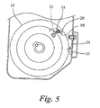
- the regulation ratchet 18 When the engine is rotated, the regulation ratchet 18 is rotated against a resilient force of the torsion coil spring 22 due to a centrifugal force thereof. As shown in Fig. 5 , the engagement pawl 28 is retracted inside an outer periphery of the fly-wheel 13 to be disengaged from the regulation cam 23 and is engaged with a pin 39 provided in the fly-wheel 13. Accordingly, the engagement pawl 28 is held in a position where the engagement pawl 28 is not engaged with the protruding pressing piece 26 of the regulation, cam 23,
- the regulation ratchet 18 is rotated by the resilient force of the torsion coil spring 22 and the engagement pawl 28 is returned to a position where the engagement pawl 28 can be engaged with the pressing piece 26 of the regulation cam 23 as shown in Fig. 2 to be located in a stand-by state as shown in Fig. 3 .
- the regulation ratchet 18 can be provided in a dead space eccentric relative to a rotational axis (the crank shaft 11) of the fly-wheel 13, a structure can be made to be Further, since the fly-wheel 13 is provided in the engine side, timing of releasing the accumulated torque can be made to correspond to a start timing fixed to a predetermined timing in the engine side. Accordingly, the timing of releasing the accumulated torque can be most efficiently set.
- the pressing unit 20 may have a structure for pressing the regulation ratchet 18 and does not necessarily need to be formed with a plurality of members.
- the internal structure of the starter is not limited to the above-described form and other known structure may be used.
- the clutch unit between the cam plate and the driving pulley is also not limited to the above-described form including the centrifugal ratchet and the cam pawl.
- a friction-type clutch unit may be used.
- As a unit for accumulating rotational energy both of a coil spring and a spiral spring can be used.
- Fig. 6 shows an embodiment where a rotation regulation unit is provided in a four cycle engine.
- a gear 30 provided at an end part of a crank shaft 11
- a cam gear 32 provided in a cam shaft 31 is engaged.
- An opening and closing operation of an intake valve (or an exhaust valve) 33 is controlled by the rotation of the cam gear 32.
- a cam 52 is provided that rotates integrally with the cam gear 32.
- the intake valve 33 is associated with the push rod 53 through a rocker arm 54.
- a gear ratio is set so that when the crank shaft 11 rotates twice, the cam gear 32 rotates once.
- the engine can be not only manually started by pulling a starter rope 5, but also started by a motor 34. Since the manual operation is described above, an explanation thereof will be omitted.
- a gear member 36 rotating integrally with the crank shaft 11 is arranged so as to be engaged with an output shaft 35 of the motor 34 connected to a battery. With a spiral groove 37 of the output shaft 35, a pinion gear 38 is engaged.
- the output shaft 35 is rotated in a starting direction
- the pinion gear 38 is moved forward to be engaged with the gear member 36.
- the gear member 36 is rotated and the pinion gear 38 relatively begins to be rotated in an opposite direction, the pinion gear 38 is moved backward along the spiral groove 37 and disengaged from the gear member 36.
- a torque-accumulation spring 8 is arranged in a housing 40 formed integrally with the output shaft 35.
- One end of the torque-accumulation spring 8 is engaged with a motor shaft 34a of the motor 34, and the other end is engaged with the housing 40.
- the rotation regulation unit includes a regulation ratchet 18 provided in the cam gear 32 to be linkedly rotated with the crank shaft 11 of the engine and a pressing unit 20 that regulates an operation of the regulation ratchet 18 by a predetermined resilient force.
- the regulation ratchet 18 has a bow-shape in which an intermediate part is bent, and is rotatably provided on a support shaft 29 fixed to an eccentric position deviating from a rotational axis of the cam gear 32. Further, one end part 18a of the regulation ratchet 18 is urged to engage with a protruding part 41 provided in a side surface of the cam gear 32 by a torsion coil spring 22 wound on the support shaft 29. At this time, the other end of the regulation ratchet 18 is provided with an engagement pawl 28.
- the pressing unit 20 includes a regulation cam 23 and a leaf spring 24.
- the regulation cam 23 is provided in an engine case 10 so as to be rotatable through a rotation shaft 25 and has a pressing piece 26 protruding from one end side of the rotation shaft 25 and an engagement piece 27 formed in the other end side.
- the pressing piece 26 is arranged so as to be engaged with the engagement pawl 28 of the .regulation ratchet 18 that protrudes outside the cam gear 32. Further, an end of the engagement piece 27 is engaged with an end portion of the leaf spring 24. Then, the engagement piece 27 is pressed to an inner side of the engine case 10 by the leaf spring 24 so that the pressing piece 26 is protruded to be engaged with the engagement pawl 28 of the regulation ratchet 18 under this state.
- the leaf spring 24 applies the resilient force to the regulation cam 23 against a rotational force thereof around the rotation shaft 25.
- the resilient force of the leaf spring 24 is set to a level the same as or higher than the torque (start torque) necessary for starting the engine.
- the cam gear 32 can be rotated and the torque accumulated in the torque-accumulation spring 8 is released at a stroke, the accumulated, torque is transmitted to the crank shaft 11 from a cam plate 4, a driving pulley 7 and a fly-wheel 13 in the manual operation, and the torque is transmitted to the crank shaft 11 from the gear member 36 in the motor operation, respectively to start the engine.
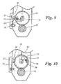
- the regulation ratchet 18 When the engine is rotated, the regulation ratchet 18 is rotated against a resilient force of the torsion coil spring 22 due to a centrifugal force thereof. As shown in Fig. 10 , the engagement pawl 28 is retracted to be disengaged from the regulation cam 23 and is engaged with a pin 39 provided in the cam gear 32. Accordingly, the engagement pawl 28 is held in a position where the engagement pawl 28 is not engaged with the protruding pressing piece 26 of the regulation cam 23.
- the regulation ratchet 18 is rotated by the resilient force of the torsion coil spring 22, and the engagement pawl 28 protrudes outside an outer periphery of the cam gear 32 and returns to a position where the engagement pawl 28 can be engaged with the pressing piece 26 of the regulation cam 23 to be located in a stand-by state.
- the regulation ratchet 18 can be provided in a dead space eccentric relative to a rotational axis of the cam gear 32, a structure can be made to be compact. Further, since the regulation ratchet 18 is attached to the cam gear 32 provided in the engine side, timing of releasing the accumulated torque can be made to correspond to a start timing fixed to a predetermined timing in the engine side. Accordingly, the timing of releasing the accumulated torque can be most efficiently set.
- the cam gear 32 of the four cycle engine is set to be rotated once when the crank shaft 11 is rotated twice.
- a stroke of suction, compression, explosion and exhaust is carried out.
- the intake valve and the exhaust valve are opened and closed, namely, a stroke of suction, compression, explosion and exhaust of a piston 15 is carried out.
- which stroke that the accumulated torque of the torque-accumulation spring 8 is to be released can be controlled depending on which place the regulation ratchet 18 is provided in the cam gear 32
- the timing of releasing the accumulated torque can be made to accurately correspond thereto.
- the cam 52 is controlled to operate the push rod 53 and the rocker arm 54 so as to open the intake valve 33.
- the above-described rotation regulation unit is provided in the fly-wheel 13 and the cam gear 32.
- a mounting place of the rotation regulation unit may be a rotating body that rotates linkedly with the crank shaft 11 of the engine.
- the gear member 36 is also a rotating body. Accordingly, the rotation regulation unit may be provided in the gear member 36.
- a unit for applying the torque to the torque-accumulation spring 8 is not limited to the above-described rotating member,
- a lever unit 43 which applies a torque to a torque-accumulation spring 8 arranged in an engine case 10, a rotating member 49 and a driving pulley 7 which transmit the torque of the torque-accumulation spring 8 to a crank shaft 11, and a rotation regulation unit which restrains the torque accumulated in the torque-accumulation spring 8 from being transmitting to start an engine.
- the lever unit 43 may include a kick lever 46 integrally provided with a sector-shaped gear 45, a first rotating member 47 having a gear 44 engaged with the sector-shaped gear 45, a second rotating member 48 connected to the first rotating member 47 through a clutch, a torque-accumulation spring 8 accommodated in the second rotating member 48, a rotating member 49 rotating by the torque of the torque-accumulation spring 8 and a driving pulley 7 connected to the rotating member 49 through a clutch.
- the driving pulley 7 is fixed to the crank shaft 11. Since the rotation regulation unit is the same as that provided in the fly-wheel 13, a detail will be omitted.
- a clutch unit 50 is provided between the first rotating member 47 and the second rotating member 48.
- a clutch unit 42 is provided between the second rotating member 48 and a housing 41.
- the torque apply unit when the kick lever 46 is operated in one direction, the first rotating member 47 is rotated, and the torque is accumulated in the torque-accumulation spring 8.
- the first rotating member 47 When a foot is disengaged from the kick lever 46, the first rotating member 47 is returned to an original position by a spring not shown in the drawing, however, the second rotating member 48 is not rotated in the opposite direction. Accordingly, while the operation is repeated, the power accumulated in the torque-accumulation spring 8 is increased, When the accumulated torque does not satisfy the spring load (resilient force) of a leaf spring 24 exceeding the rotational resistance of the engine, a cam plate 4 is not rotated. On the contrary, when the torque-accumulation spring 8 is wound and fastened, the torque accumulated in the torque-accumulation spring 8 is increased.
- the torque apply unit may be reciprocated to accumulate the torque little by little in the torque-accumulation spring 8.
Abstract
Description
- This application claims priorities from Japanese Patent Application No.
2010-018584 filed on January 29, 2010 - The present invention relates to a starter that can sufficiently accumulate a torque required for starting an engine, in a torque-accumulation spring.
- An ordinary starter for a small engine includes a driving pulley, a cam plate, a torque-accumulation spring and a casket. The driving pulley is fixed to a crank shaft of the engine. In the driving pulley, a centrifugal ratchet is provided to be engaged with a cam pawl provided in the cam plate. And, the casket is connected to the cam plate through the torque-accumulation spring.
- To start the engine, the casket is rotated by a hand or a motor to accumulate a torque (energy) in the torque-accumulation spring. When the accumulated torque exceeds a rotational resistance of the engine, the accumulated torque is released at a stroke to the crank shaft through the cam plate and the pulley, thereby starting the engine (for instance, see
JP-2002-227753-A - That is, when such a torque as to exceed the rotational resistance of the engine is accumulated in the torque-accumulation spring, the engine can be rotated by the accumulated torque. However, the rotational resistance of the engine does not always have a constant resistance value. For instance, when a piston is located around an upper dead point, the rotational resistance of the engine becomes highest, and when the piston is located around a lower dead point, the rotational resistance of the engine becomes lowest.
- When the rotational resistance is low, the torque accumulated in the torque-accumulation spring will be released even before the accumulated torque reaches a start torque necessary for starting the engine, and the cam plate will be rotated with an insufficient torque. In this case, since the torque transmitted to the driving pulley does not reach the start torque, the engine can not be assuredly started.
- To solve this problem, a rotation regulation unit may be provided to regulate a rotation of a member such as a cam plate until a sufficient torque (energy) is accumulated in a torque-accumulation spring. The rotation regulation unit releases the accumulated torque after the sufficient energy is accumulated to thereby start an engine irrespective of a variation in the rotational resistance of the engine, and (see
JP-2006-342717-A - However, in
JP-2006-342717-A - Further, when the starter is attached to the engine, the rotation regulation unit of the starter side needs to be aligned with a crank shaft of the engine side. Such operation is troublesome.
- One object of the present invention is to provide a starter for a small engine in which a rotation regulation unit is provided in an engine side so as to stabilize timing for releasing an accumulated torque and so as to omit a necessity for alignment between a starter side and the engine side.
- According to a first aspect of the present invention, there is provided a starter for a small engine, including: a torque apply unit that applies a torque to a torque-accumulation spring arranged in a starter case; a rotating member provided in the starter case to transmit the torque accumulated in the torque-accumulation spring to a crankshaft of the engine; a driving pulley provided integrally with the crankshaft to be engaged with and disengaged from the rotating member; and a rotation regulation unit that restrains the torque accumulated in the torque-accumulation spring from being transmitted to the crankshaft, wherein the rotation regulation unit includes: a regulation ratchet provided on a rotating body at an eccentric position thereof, the rotating body being linked with the crank shaft to rotate therewith; and a pressing unit provided on an engine case to be engaged with the regulation ratchet and to regulate an operation of the regulation ratchet by a predetermined resilient force, and wherein the regulation ratchet is disengaged from the pressing unit by the torque accumulated in the torque-accumulation spring when the accumulated torque exceeds the resilient force, so that the rotating body and the crankshaft are rotated to thereby start the engine.
- According to a second aspect of the present invention, there is provided a starter for a small engine, including: motor that applies a torque to a torque-accumulation spring arranged in an engine case; a gear member that transmits the torque accumulated in the torque-accumulation spring to a crank shaft of the engine; and a rotation regulation unit that restrains the torque accumulated in the torque-accumulation spring from being transmitted to the crankshaft, wherein the rotation regulation unit includes: a regulation ratchet provided on a rotating body at an eccentric position thereof, the rotating body being linked with the crank shaft to rotate therewith; and a pressing unit provided on an engine case to be engaged with the regulation ratchet and to regulate an operation of the regulation ratchet by a predetermined resilient force, and wherein the regulation ratchet is disengaged from the pressing unit by the torque accumulated in the torque-accumulation spring when the accumulated torque exceeds the resilient force, so that the rotating body and the crankshaft, are rotated to thereby start the engine.
- According to a third aspect of the present invention, there is provided the starter, wherein the rotating body is a fly-wheel of the engine.
- According to a fourth aspect of the present invention, there is provided the starter, wherein the rotating body is the gear member.
- According to a fifth aspect of the present invention, there is provided the starter, wherein the rotating body is a cam gear provided in the engine between the crank shaft and an intake or exhaust valve.
- According to a sixth aspect of the present invention, there is provided a starter for a small engine, including: a lever unit that applies a torque to a torque-accumulation spring arranged in an engine case; a rotating member that transmits the torque accumulated in the torque-accumulation spring to a crank shaft of the engine; and a rotation regulation unit that restrains the torque accumulated in the torque-accumulation spring from being transmitted to the crankshaft, wherein the rotation regulation unit includes: a regulation ratchet provided on a rotating body at an eccentric position thereof, the rotating body being linked with the crank shaft to rotate therewith; and a pressing unit provided on an engine case to be engaged with the regulation ratchet and to regulate an operation of the regulation ratchet by a predetermined resilient force, and wherein the regulation ratchet is disengaged from the pressing unit by the torque accumulated in the torque-accumulation spring when the accumulated torque exceeds the resilient force, so that the rotating body and the crankshaft are rotated to thereby start the engine.
- According to the first aspect, the rotation regulation unit includes the regulation ratchet provided at the eccentric position of the rotating body that rotates linkedly with the crank shaft of the engine and the pressing unit that is engaged with the regulation ratchet from the engine case side and regulates an operation of the regulation ratchet by the predetermined resilient force, and when the torque accumulated in the torque-accumulation spring exceeds the resilient force, the regulation ratchet is disengaged from the pressing unit by the torque to release the torque accumulated in the torque-accumulation spring, rotates the rotating body and starts the engine. Accordingly, a sufficient torque can be accumulated in the torque-accumulation spring irrespective of a variation in the rotational resistance of the engine and the engine can be assuredly started.
- Further, in the engine side, start timing is fixed to a predetermined timing. Since the rotation regulation unit is provided in the engine side, timing of releasing the accumulated torque can be made to correspond to the start timing. Accordingly, the timing of releasing the accumulated torque can be most efficiently set.
- In the related art, when the starter is attached to the engine, the rotation regulation unit of the starter side needs to be aligned with the crank shaft of the engine side. However, since the rotation regulation unit is previously provided in the engine side, an alignment operation is not necessary.
- Further, since the rotation regulation unit is accommodated in the engine case, the starter case that accommodates main parts of the starter is not enlarged and an entire structure can be made compact.
- According to the second aspect, the rotation regulation unit includes the regulation ratchet provided at the eccentric position of the rotating body that rotates linkedly with the crank shaft of the engine and the pressing unit that is engaged with the regulation ratchet from the engine case side and regulates an operation of the regulation ratchet by the predetermined resilient force. Further, According to the third aspect, the rotating body is formed with the fly-wheel. Accordingly, the same effects as those by the first aspect can be obtained. Effects by the force aspect are the same as those by the first aspect.
- According to the fifth aspect, the rotating body is the cam gear provided between the crank shaft of the engine and the intake valve or the exhaust valve. The cam gear of the four cycle engine is set to be rotated once when the crank shaft is rotated twice. In the four cycle engine, when the crank shaft is rotated twice, a stroke of suction, compression, explosion and exhaust is carried out. Accordingly, every time that the cam gear is rotated once, the intake valve and the exhaust valve are opened and closed, namely, a stroke of suction, compression, explosion and exhaust of a piston is carried out. Namely, which stroke that the accumulated torque is to be released can be controlled depending on which place the regulation ratchet is provided in the cam gear. The timing of releasing the accumulated torque can be made to accurately correspond thereto.
- According to sixth aspect, since the rotation applying unit that applies the torque to the torque-accumulation spring arranged in the engine case is formed with the lever unit, when the torque is accumulated little by little in the torque-accumulation spring by a reciprocating movement, the rotation of the engine can be regulated.
-
-
Fig. 1 cross-sectionally illustrates a starter of a first embodiment. -
Fig. 2 illustrates a side view of the starter immediately before the rotation of a fly-wheel is regulated, the side view being taken along a line X-X inFig. 1 . -
Fig. 3 illustrates the side view where the rotation of the fly-wheel is regulated. -
Fig. 4 illustrates the side view immediately before the regulation of the rotation of the fly-wheel is released. -
Fig. 5 illustrates the side view where the engine is started by the starter. -
Fig. 6 cross-sectionally illustrates a starter of a second embodiment. -
Fig. 7 illustrates a side view of the starter immediately before the rotation of a cam gear is regulated, the side view being taken along a line Y-Y inFig. 6 . -
Fig. 8 illustrates the side view where the rotation of the cam gear is regulated. -
Fig. 9 illustrates the side view immediately before the regulation of the rotation of the cam gear is released. -
Fig. 10 illustrates the side view where the engine is started by the starter. -
Fig. 11A schematically illustrates a starter with a rotation applying unit by a kick lever, andFig. 11B illustrates a front view of the kick lever. - In
Fig. 1 , a starter case 1 is illustrated. In the starter case 1, asupport shaft 2 protrudes to rotatably support arope reel 3 and a cam plate 4 thereon. - An accommodating groove for a
starter rope 5 is formed in an outer peripheral side of therope reel 3, and an accommodating part of areturn spring 6 is formed in an outer side of therope reel 3. A torque-accumulation spring 8 is accommodated in an inner side of therope reel 3. One end of the torque-accumulation spring 8 is engaged with therope reel 3, and the other end is engaged with an end part of the cam plate 4. Although spiral springs are illustrated in the drawing as thereturn spring 6 and the torque-accumulation spring 8, a coil spring may be used in place of the spiral spring. - The cam plate 4 is a rotating member which can be engaged with a driving pulley 7 fixed to a crank
shaft 11 of an engine. The cam plate 4 is rotatably supported by thesupport shaft 2. - The cam plate 4 and the driving pulley 7 are connected through a clutch, so as to be engaged with and disengaged from each other. For example, such configuration is disclosed in
JP-2002-227753-A - According to the above-described structure, when the
starter rope 5 is pulled, therope reel 3 is rotated, and the torque-accumulation spring 8 is wound to accumulate a torque. When the accumulated torque reaches a predetermined level or higher, the cam plate 4 is rotated. When the cam plate 4 is rotated, the torque is transmitted to the driving pulley 7. - Then, the rotation of the driving pulley 7 is transmitted to the
crank shaft 11 arranged in anengine case 10 to star the engine. - To one end of the
crank shaft 11, a fly-wheel (rotating body) 13 connected integrally to the driving pulley 7 is rotatably supported. Further, to thecrank shaft 11, apiston 15 slidably accommodated in acylinder 16 is connected through a connectingrod 14. - In the fly-
wheel 13, amagnet 17 is provided, so that a spark can be shot to a plug. - In such a way, the torque is accumulated in the torque-accumulation spring 8 by a rotation applying unit (the
rope reel 3 and the starter rope 5). The accumulated torque finally exceeds a rotational resistance of the engine to rotate the cam plate 4 and rotate thecrank shaft 11 in accordance with the rotation of the driving pulley 7. - However, for instance, when the rotational resistance of the engine is occasionally low, the cam plate 4 may be rotated with the torque insufficient for starting the engine, so that the torque necessary for starting the engine cannot be transmitted to the driving pulley 7.
- A starter for a small engine according to the embodiment has a rotation regulation unit (torque limiter) that restrains the torque accumulated in the torque-accumulation spring 8 from being transmitting to the engine side until the accumulated torque reaches a starting torque necessary for starting the engine irrespective of a variation in the rotational resistance of the engine.
- As shown in
Fig. 2 , the rotation regulation unit includes aregulation ratchet 18 provided in the fly-wheel 13 to be linkedly rotated with thecrank shaft 11 of the engine and apressing unit 20 that regulates an operation of theregulation ratchet 18 by a predetermined resilient force. - The
regulation ratchet 18 has a substantially bow-shape in which an intermediate part is bent, and is rotatably provided on asupport shaft 21 fixed to an eccentric position deviating from a rotational axis of the fly-wheel 13. Further, oneend part 18a of theregulation ratchet 18 is urged to engage with a protrudingpart 19 provided in one side surface of the fly-wheel 13 by atorsion coil spring 22 wound on thesupport shaft 21. The other end of theregulation ratchet 18 is provided with anengagement pawl 28. - The
pressing unit 20 includes aregulation cam 23 and a leaf spring (resilient unit) 24. - The
regulation cam 23 is provided in theengine case 10 side so as to be rotatable through arotation shaft 25 and has apressing piece 26 protruding from one end side of therotation shaft 25 and anengagement piece 27 formed in the other end side. Thepressing piece 26 is arranged so as to be engaged with theengagement pawl 28 of theregulation ratchet 18 that protrudes outside the fly-wheel 13. Further, an end of theengagement piece 27 is engaged with an end portion of theleaf spring 24. Then, theengagement piece 27 is pressed to a central side of the fly-wheel 13 by theleaf spring 24 so that thepressing piece 26 is protruded to be engaged with theengagement pawl 28 of theregulation ratchet 18. - In such a way, the
leaf spring 24 applies the resilient force to theregulation cam 23 against a rotational force thereof around therotation shaft 25. The resilient force of theleaf spring 24 is set to a level the same as or higher than the torque (the starting torque) necessary for starting the engine. - An operation of the above-described rotation regulation unit will be descried below. Ordinarily, as shown in
Fig. 3 , since theengagement pawl 28 of theregulation ratchet 18 is engaged with thepressing piece 26 of theregulation cam 23 and theregulation cam 23 holds an engaged state by the resilient force of theleaf spring 24, even when thestarter rope 5 is pulled or therope reel 3 is rotated, the cam plate 4 cannot be rotated. In such a way, when the accumulated torque does not satisfy the spring load (resilient force) of theleaf spring 24 exceeding the rotational resistance of the engine, the cam plate 4 is not rotated. On the contrary, when the torque-accumulation spring 8 is wound and fastened, the torque accumulated in the torque-accumulation spring 8 is increased. When the accumulated torque exceeds the resilient force of theleaf spring 24, as shown inFig. 4 , thepressing piece 26 of theregulation cam 23 is pressed by theengagement pawl 28 of theregulation ratchet 18 to be retraced. Thus, the fly-wheel 13 rotates little by little. Finally, as shown inFig. 5 , theengagement pawl 28 is disengaged from thepressing piece 26. Accordingly, since the torque accumulated in the torque-accumulation spring 8 is released at a stroke, the accumulated torque is transmitted to the cam plate 4. The torque of the cam plate 4 is transmitted to the fly-wheel 13 through the clutch unit to rotate the fly-wheel and the engine is started. - When the engine is rotated, the
regulation ratchet 18 is rotated against a resilient force of thetorsion coil spring 22 due to a centrifugal force thereof. As shown inFig. 5 , theengagement pawl 28 is retracted inside an outer periphery of the fly-wheel 13 to be disengaged from theregulation cam 23 and is engaged with apin 39 provided in the fly-wheel 13. Accordingly, theengagement pawl 28 is held in a position where theengagement pawl 28 is not engaged with the protruding pressingpiece 26 of the regulation,cam 23, - After that, when the rotation of the engine is stopped, the
regulation ratchet 18 is rotated by the resilient force of thetorsion coil spring 22 and theengagement pawl 28 is returned to a position where theengagement pawl 28 can be engaged with thepressing piece 26 of theregulation cam 23 as shown inFig. 2 to be located in a stand-by state as shown inFig. 3 . - Since the
regulation ratchet 18 can be provided in a dead space eccentric relative to a rotational axis (the crank shaft 11) of the fly-wheel 13, a structure can be made to be Further, since the fly-wheel 13 is provided in the engine side, timing of releasing the accumulated torque can be made to correspond to a start timing fixed to a predetermined timing in the engine side. Accordingly, the timing of releasing the accumulated torque can be most efficiently set. - In the related art, when the starter is attached to the engine, the rotation regulation unit of the starter side needs to be aligned with the crank shaft of the engine side. However, in the present embodiment, since the rotation regulation unit is previously provided in the engine side, an alignment operation is not necessary.
- The
pressing unit 20 may have a structure for pressing theregulation ratchet 18 and does not necessarily need to be formed with a plurality of members. - For example, the internal structure of the starter is not limited to the above-described form and other known structure may be used. The clutch unit between the cam plate and the driving pulley is also not limited to the above-described form including the centrifugal ratchet and the cam pawl. For instance, a friction-type clutch unit may be used. As a unit for accumulating rotational energy, both of a coil spring and a spiral spring can be used.
-
Fig. 6 shows an embodiment where a rotation regulation unit is provided in a four cycle engine. InFig. 6 , with agear 30 provided at an end part of acrank shaft 11, acam gear 32 provided in acam shaft 31 is engaged. An opening and closing operation of an intake valve (or an exhaust valve) 33 is controlled by the rotation of thecam gear 32. In thecam shaft 31, acam 52 is provided that rotates integrally with thecam gear 32. With thecam 52, apush rod 53 is engaged. Theintake valve 33 is associated with thepush rod 53 through arocker arm 54. A gear ratio is set so that when thecrank shaft 11 rotates twice, thecam gear 32 rotates once. - The engine can be not only manually started by pulling a
starter rope 5, but also started by amotor 34. Since the manual operation is described above, an explanation thereof will be omitted. In the motor operation, agear member 36 rotating integrally with thecrank shaft 11 is arranged so as to be engaged with anoutput shaft 35 of themotor 34 connected to a battery. With aspiral groove 37 of theoutput shaft 35, apinion gear 38 is engaged. When theoutput shaft 35 is rotated in a starting direction, thepinion gear 38 is moved forward to be engaged with thegear member 36. When the engine is started, thegear member 36 is rotated and thepinion gear 38 relatively begins to be rotated in an opposite direction, thepinion gear 38 is moved backward along thespiral groove 37 and disengaged from thegear member 36. Further, in ahousing 40 formed integrally with theoutput shaft 35, a torque-accumulation spring 8 is arranged. One end of the torque-accumulation spring 8 is engaged with amotor shaft 34a of themotor 34, and the other end is engaged with thehousing 40. Thus, when themotor 34 is rotated, a torque is applied to the torque-accumulation spring 8. - The rotation regulation unit includes a
regulation ratchet 18 provided in thecam gear 32 to be linkedly rotated with thecrank shaft 11 of the engine and apressing unit 20 that regulates an operation of theregulation ratchet 18 by a predetermined resilient force. - As shown in
Fig. 7 , theregulation ratchet 18 has a bow-shape in which an intermediate part is bent, and is rotatably provided on asupport shaft 29 fixed to an eccentric position deviating from a rotational axis of thecam gear 32. Further, oneend part 18a of theregulation ratchet 18 is urged to engage with a protrudingpart 41 provided in a side surface of thecam gear 32 by atorsion coil spring 22 wound on thesupport shaft 29. At this time, the other end of theregulation ratchet 18 is provided with anengagement pawl 28. - The
pressing unit 20 includes aregulation cam 23 and aleaf spring 24. - The
regulation cam 23 is provided in anengine case 10 so as to be rotatable through arotation shaft 25 and has apressing piece 26 protruding from one end side of therotation shaft 25 and anengagement piece 27 formed in the other end side. Thepressing piece 26 is arranged so as to be engaged with theengagement pawl 28 of the .regulation ratchet 18 that protrudes outside thecam gear 32. Further, an end of theengagement piece 27 is engaged with an end portion of theleaf spring 24. Then, theengagement piece 27 is pressed to an inner side of theengine case 10 by theleaf spring 24 so that thepressing piece 26 is protruded to be engaged with theengagement pawl 28 of theregulation ratchet 18 under this state. - In such a way, the
leaf spring 24 applies the resilient force to theregulation cam 23 against a rotational force thereof around therotation shaft 25. The resilient force of theleaf spring 24 is set to a level the same as or higher than the torque (start torque) necessary for starting the engine. - An operation of the above-described rotation regulation unit will be described below. Ordinarily, as shown in
Fig. 8 , since theengagement pawl 28 of theregulation ratchet 18 is engaged with thepressing piece 26 of theregulation cam 23 and theregulation cam 23 is held in an engaged state by the resilient force of theleaf spring 24, thecrank shaft 11 is hardly rotated. Even when thestarter rope 5 is pulled to rotate arope reel 3 is rotated, or themotor 34 is operated, thecrank shaft 11 is not immediately rotated and the torque is accumulated in the torque-accumulation spring 8. When the accumulated torque does not satisfy a spring load (resilient force) of theleaf spring 24 exceeding the rotational resistance of the engine, thecrank shaft 11 is not rotated. On the contrary, when the torque-accumulation spring 8 is wound and fastened, the torque accumulated in the torque-accumulation, spring 8 is increased. When the accumulated torque exceeds the resilient force of theleaf spring 24, thepressing piece 26 of theregulation cam 23 is pressed by theengagement pawl 28 of theregulation ratchet 18 to be retracted. Thus, thecam gear 32 rotates little by little. Then, finally, as shown inFig. 9 , theengagement pawl 28 is disengaged from thepressing piece 26. Thus, since thecam gear 32 can be rotated and the torque accumulated in the torque-accumulation spring 8 is released at a stroke, the accumulated, torque is transmitted to thecrank shaft 11 from a cam plate 4, a driving pulley 7 and a fly-wheel 13 in the manual operation, and the torque is transmitted to thecrank shaft 11 from thegear member 36 in the motor operation, respectively to start the engine. - When the engine is rotated, the
regulation ratchet 18 is rotated against a resilient force of thetorsion coil spring 22 due to a centrifugal force thereof. As shown inFig. 10 , theengagement pawl 28 is retracted to be disengaged from theregulation cam 23 and is engaged with apin 39 provided in thecam gear 32. Accordingly, theengagement pawl 28 is held in a position where theengagement pawl 28 is not engaged with the protruding pressingpiece 26 of theregulation cam 23. - After that, when the rotation of the engine is stopped, the
regulation ratchet 18 is rotated by the resilient force of thetorsion coil spring 22, and theengagement pawl 28 protrudes outside an outer periphery of thecam gear 32 and returns to a position where theengagement pawl 28 can be engaged with thepressing piece 26 of theregulation cam 23 to be located in a stand-by state. - Since the
regulation ratchet 18 can be provided in a dead space eccentric relative to a rotational axis of thecam gear 32, a structure can be made to be compact. Further, since theregulation ratchet 18 is attached to thecam gear 32 provided in the engine side, timing of releasing the accumulated torque can be made to correspond to a start timing fixed to a predetermined timing in the engine side. Accordingly, the timing of releasing the accumulated torque can be most efficiently set. - In the above-described embodiment, when the starter is attached to the engine, an alignment operation is not necessary.
- Further, the
cam gear 32 of the four cycle engine is set to be rotated once when thecrank shaft 11 is rotated twice. In the four cycle engine, when thecrank shaft 11 is rotated twice, a stroke of suction, compression, explosion and exhaust is carried out. Accordingly, every time that thecam gear 32 is rotated once, the intake valve and the exhaust valve are opened and closed, namely, a stroke of suction, compression, explosion and exhaust of apiston 15 is carried out. Namely, which stroke that the accumulated torque of the torque-accumulation spring 8 is to be released can be controlled depending on which place theregulation ratchet 18 is provided in thecam gear 32 The timing of releasing the accumulated torque can be made to accurately correspond thereto. For instance, in the above-described embodiment, at a position shown inFigs. 9 to 10 , thecam 52 is controlled to operate thepush rod 53 and therocker arm 54 so as to open theintake valve 33. - The above-described rotation regulation unit is provided in the fly-
wheel 13 and thecam gear 32. However, a mounting place of the rotation regulation unit may be a rotating body that rotates linkedly with thecrank shaft 11 of the engine. Thegear member 36 is also a rotating body. Accordingly, the rotation regulation unit may be provided in thegear member 36. - A unit for applying the torque to the torque-accumulation spring 8 is not limited to the above-described rotating member, For instance, as shown in
Figs. 11A and 11B , there may be provided a structure where alever unit 43 which applies a torque to a torque-accumulation spring 8 arranged in anengine case 10, a rotatingmember 49 and a driving pulley 7 which transmit the torque of the torque-accumulation spring 8 to a crankshaft 11, and a rotation regulation unit which restrains the torque accumulated in the torque-accumulation spring 8 from being transmitting to start an engine. - Specifically, the
lever unit 43 may include akick lever 46 integrally provided with a sector-shapedgear 45, a first rotatingmember 47 having agear 44 engaged with the sector-shapedgear 45, a second rotatingmember 48 connected to the first rotatingmember 47 through a clutch, a torque-accumulation spring 8 accommodated in the second rotatingmember 48, a rotatingmember 49 rotating by the torque of the torque-accumulation spring 8 and a driving pulley 7 connected to the rotatingmember 49 through a clutch. The driving pulley 7 is fixed to thecrank shaft 11. Since the rotation regulation unit is the same as that provided in the fly-wheel 13, a detail will be omitted. - Between the first rotating
member 47 and the second rotatingmember 48, aclutch unit 50 is provided. Between the second rotatingmember 48 and ahousing 41, aclutch unit 42 is provided. Thus, only when the first rotatingmember 47 is rotated in one direction, the second rotatingmember 48 is rotated. Since the second rotatingmember 48 cannot be rotated in an opposite direction by theclutch unit 42, even when the first rotatingmember 47 is rotated in the opposite direction, the second rotatingmember 48 cannot be rotated and is held under a state that a rotation is stopped. - According to the torque apply unit, when the
kick lever 46 is operated in one direction, the first rotatingmember 47 is rotated, and the torque is accumulated in the torque-accumulation spring 8. When a foot is disengaged from thekick lever 46, the first rotatingmember 47 is returned to an original position by a spring not shown in the drawing, however, the second rotatingmember 48 is not rotated in the opposite direction. Accordingly, while the operation is repeated, the power accumulated in the torque-accumulation spring 8 is increased, When the accumulated torque does not satisfy the spring load (resilient force) of aleaf spring 24 exceeding the rotational resistance of the engine, a cam plate 4 is not rotated. On the contrary, when the torque-accumulation spring 8 is wound and fastened, the torque accumulated in the torque-accumulation spring 8 is increased. When the accumulated torque exceeds the resilient force of theleaf spring 24, a fly-wheel 13 rotates little by little. Thus, as shown inFig. 3 , apressing piece 26 of aregulation cam 23 is pressed by anengagement pawl 28 of aregulation ratchet 18 to be retracted. Finally, as shown inFigs. 4 and5 , theengagement pawl 28 is disengaged from thepressing piece 26. Accordingly, since the torque accumulated in the torque-accumulation spring 8 is released at a stroke, the accumulated torque is transmitted to thecrank shaft 11 to start the engine. - As described above, the torque apply unit may be reciprocated to accumulate the torque little by little in the torque-accumulation spring 8.
- It is explicitly stated that all features disclosed in the description and/or the claims are intended to be disclosed separately and independently from each other for the purpose of original disclosure as well as for the purpose of restricting the claimed invention independent of the composition of the features in the embodiments and/or the claims. It is explicitly stated that all value rangers or indications of groups of entities disclose every possible intermediate value or intermediate entity for the purpose of original disclosure as well as for the purpose of restricting the claimed invention, in particular as limits of value ranges.
Claims (7)
- A starter for a small engine, comprising:a torque apply unit (3, 5; 34; 43) that applies a torque to a torque-accumulation spring (8) arranged in a starter case (1) or an engine case;a rotating member (4; 36) provided in the starter case to transmit the torque accumulate in the torque-accumulation spring (8) to a crankshaft, (11) of the engine; anda rotation regulation unit that restrains the torque accumulated in the torque-accumulation spring (8) from being transmitted to the crankshaft; (11),wherein the rotation regulation unit includes:a regulation ratchet (18) provided on a rotating body (13; 32: 36) at an eccentric position thereof, the rotating body (13; 32; 36) being linked with the crankshaft, (11) to rotate therewith; anda pressing unit (20) provided on an engine case to be engaged with the regulation ratchet (18) and to regulate an operation of the regulation ratchet (18) by a predetermined resilient force, andwherein the regulation ratchet (18) is disengaged from the pressing unit (20) by the torque accumulated in the torque-accumulation spring when the accumulated torque exceeds the resilient force, so that the rotating body (13; 32; 36) and the crankshaft (11) are rotated to thereby start the engine.
- The starter of Claim 1, wherein the torque apply unit is a motor (34) that applies a torque to the torque-accumulation spring (8) arranged in the engine case; and
the rotating member is a gear member (36) that transmits the torque accumulated in the torque-accumulation spring (8) to the crankshaft (11) of the engine. - The starter of Claim 1, wherein the torque apply unit is a lever unit (43) that applies a torque to the torque-accumulation spring (8) arranged in the engine case.
- The starter of Claim 2,
wherein the rotating body is the gear member (36). - The starter of Claim 1,
wherein a driving pulley (7) is provided integrally with the crankshaft (11) to be engaged with and disengaged from the rotating member (4). - The starter of Claim 1, 2, 3 or 5,
wherein the rotating body is a fly-wheel (13) of the engine. - The starter of Claim 1, 2, 3 or 5,
wherein the rotating body is a cam gear (32) provided in the engine between the crankshaft (11) and an intake or exhaust valve.
Applications Claiming Priority (1)
| Application Number | Priority Date | Filing Date | Title |
|---|---|---|---|
| JP2010018584A JP5515045B2 (en) | 2010-01-29 | 2010-01-29 | Small engine starter |
Publications (3)
| Publication Number | Publication Date |
|---|---|
| EP2365208A2 true EP2365208A2 (en) | 2011-09-14 |
| EP2365208A3 EP2365208A3 (en) | 2013-05-29 |
| EP2365208B1 EP2365208B1 (en) | 2020-07-15 |
Family
ID=44312364
Family Applications (1)
| Application Number | Title | Priority Date | Filing Date |
|---|---|---|---|
| EP11152273.6A Active EP2365208B1 (en) | 2010-01-29 | 2011-01-26 | Starter for small engine |
Country Status (4)
| Country | Link |
|---|---|
| US (1) | US8286604B2 (en) |
| EP (1) | EP2365208B1 (en) |
| JP (1) | JP5515045B2 (en) |
| CN (1) | CN102140987B (en) |
Families Citing this family (5)
| Publication number | Priority date | Publication date | Assignee | Title |
|---|---|---|---|---|
| JP5428093B2 (en) * | 2009-08-29 | 2014-02-26 | スターテング工業株式会社 | Small engine starter |
| US8683985B2 (en) * | 2010-06-14 | 2014-04-01 | Stephen J. Thomson | Belted gear assembly for driving a supercharger |
| DE102013011978B3 (en) * | 2013-07-18 | 2014-11-06 | Andreas Reichart | Starter unit for a mobile device with an internal combustion engine |
| JP7061311B2 (en) * | 2018-04-20 | 2022-04-28 | スターテング工業株式会社 | Engine starter |
| US11319915B2 (en) | 2020-06-11 | 2022-05-03 | Kohler Co. | Engine system, and method of starting the engine |
Citations (3)
| Publication number | Priority date | Publication date | Assignee | Title |
|---|---|---|---|---|
| JP2002227753A (en) | 2001-01-31 | 2002-08-14 | Starting Ind Co Ltd | Starting device for engine |
| JP2006342717A (en) | 2005-06-08 | 2006-12-21 | Starting Ind Co Ltd | Starter of small engine |
| JP2010018584A (en) | 2008-07-14 | 2010-01-28 | Toyobo Co Ltd | COSMETIC COMPOSITION CONTAINING POLY-gamma-L-GLUTAMIC ACID AND/OR ITS SALT |
Family Cites Families (18)
| Publication number | Priority date | Publication date | Assignee | Title |
|---|---|---|---|---|
| JPS5624309Y2 (en) * | 1976-08-05 | 1981-06-08 | ||
| JPS644973U (en) * | 1987-06-27 | 1989-01-12 | ||
| JPH01190965A (en) * | 1988-01-22 | 1989-08-01 | Mitsubishi Heavy Ind Ltd | Spiral spring type starter device for internal combustion engine |
| US5083534A (en) * | 1989-04-05 | 1992-01-28 | Mitsubishi Jukogyo Kabushiki Kaisha | Spiral spring type starter apparatus for an internal combustion engine |
| JPH0717810Y2 (en) * | 1989-07-19 | 1995-04-26 | 株式会社共立 | Accumulator type starter |
| JPH07174061A (en) * | 1993-05-07 | 1995-07-11 | Nitsukari:Kk | Force storage type recoil starter |
| JP4017792B2 (en) * | 1999-08-25 | 2007-12-05 | 株式会社共立 | Accumulated starter device |
| US6508220B1 (en) * | 1999-08-25 | 2003-01-21 | Kioritz Corporation | Starter |
| ES2283472T3 (en) * | 2001-04-27 | 2007-11-01 | Maruyama Mfg. Co., Inc. | STARTER MOTOR FOR INTERNAL COMBUSTION ENGINES. |
| JP2004068639A (en) * | 2002-08-02 | 2004-03-04 | Showa Kiki Kogyo Kk | Lock-type power accumulation starter |
| JP4022456B2 (en) * | 2002-09-19 | 2007-12-19 | 株式会社クボタ | Engine recoil starter |
| TWI236518B (en) * | 2002-10-29 | 2005-07-21 | Honda Motor Co Ltd | Engine of compression-ratio variable type |
| JP3944053B2 (en) * | 2002-10-29 | 2007-07-11 | 本田技研工業株式会社 | Variable compression ratio engine |
| JP3878564B2 (en) * | 2003-02-28 | 2007-02-07 | スターテング工業株式会社 | Accumulated recoil starter |
| JP2004285875A (en) * | 2003-03-20 | 2004-10-14 | Kubota Corp | Recoil starter for engine |
| JP2005207301A (en) * | 2004-01-22 | 2005-08-04 | Kubota Corp | Recoil starter of engine |
| CN201125819Y (en) * | 2007-11-16 | 2008-10-01 | 董岩富 | Foot pedal motorcycle starting device |
| JP5428093B2 (en) * | 2009-08-29 | 2014-02-26 | スターテング工業株式会社 | Small engine starter |
-
2010
- 2010-01-29 JP JP2010018584A patent/JP5515045B2/en active Active
-
2011
- 2011-01-21 US US13/010,876 patent/US8286604B2/en active Active
- 2011-01-26 EP EP11152273.6A patent/EP2365208B1/en active Active
- 2011-01-28 CN CN201110034256.0A patent/CN102140987B/en active Active
Patent Citations (3)
| Publication number | Priority date | Publication date | Assignee | Title |
|---|---|---|---|---|
| JP2002227753A (en) | 2001-01-31 | 2002-08-14 | Starting Ind Co Ltd | Starting device for engine |
| JP2006342717A (en) | 2005-06-08 | 2006-12-21 | Starting Ind Co Ltd | Starter of small engine |
| JP2010018584A (en) | 2008-07-14 | 2010-01-28 | Toyobo Co Ltd | COSMETIC COMPOSITION CONTAINING POLY-gamma-L-GLUTAMIC ACID AND/OR ITS SALT |
Also Published As
| Publication number | Publication date |
|---|---|
| JP5515045B2 (en) | 2014-06-11 |
| EP2365208A3 (en) | 2013-05-29 |
| EP2365208B1 (en) | 2020-07-15 |
| US20110185999A1 (en) | 2011-08-04 |
| US8286604B2 (en) | 2012-10-16 |
| CN102140987A (en) | 2011-08-03 |
| CN102140987B (en) | 2015-07-22 |
| JP2011157839A (en) | 2011-08-18 |
Similar Documents
| Publication | Publication Date | Title |
|---|---|---|
| US8286604B2 (en) | Starter for small engine | |
| US6508220B1 (en) | Starter | |
| EP1596060A2 (en) | Energy storing starter assembly | |
| CN103946576A (en) | Alternator isolating decoupler | |
| US8616170B2 (en) | Recoil starter | |
| US7219569B2 (en) | Integral one-way overrun clutch with epcicycle gear system | |
| EP2593663B1 (en) | Starting device for an internal combustion engine | |
| CN209145754U (en) | Motorcycle engine electric startup structure | |
| EP3084205B1 (en) | Starting device for an internal combustion engine | |
| JP3274671B2 (en) | Starter device | |
| JP2013137014A (en) | Starter | |
| WO2013145299A1 (en) | Starter | |
| CN108368816B (en) | Starting device and method for starting an internal combustion engine equipped with a dual mass flywheel | |
| CN107709831B (en) | Dual mode tensioner | |
| JP2003013827A (en) | Recoil starter of engine | |
| RU2079698C1 (en) | Two stroke internal combustion engine with starting aid | |
| JP2008095594A (en) | Starter | |
| CA2369424A1 (en) | Engine starting apparatus | |
| TW201905319A (en) | Engine with decompression device | |
| JPH0527281U (en) | Engine starter | |
| JP2002161836A (en) | Starter device |
Legal Events
| Date | Code | Title | Description |
|---|---|---|---|
| PUAI | Public reference made under article 153(3) epc to a published international application that has entered the european phase |
Free format text: ORIGINAL CODE: 0009012 |
|
| AK | Designated contracting states |
Kind code of ref document: A2 Designated state(s): AL AT BE BG CH CY CZ DE DK EE ES FI FR GB GR HR HU IE IS IT LI LT LU LV MC MK MT NL NO PL PT RO RS SE SI SK SM TR |
|
| AX | Request for extension of the european patent |
Extension state: BA ME |
|
| PUAL | Search report despatched |
Free format text: ORIGINAL CODE: 0009013 |
|
| AK | Designated contracting states |
Kind code of ref document: A3 Designated state(s): AL AT BE BG CH CY CZ DE DK EE ES FI FR GB GR HR HU IE IS IT LI LT LU LV MC MK MT NL NO PL PT RO RS SE SI SK SM TR |
|
| AX | Request for extension of the european patent |
Extension state: BA ME |
|
| RIC1 | Information provided on ipc code assigned before grant |
Ipc: F02N 3/02 20060101AFI20130419BHEP Ipc: F02N 5/02 20060101ALI20130419BHEP Ipc: F02N 15/02 20060101ALI20130419BHEP Ipc: F02N 3/00 20060101ALI20130419BHEP Ipc: F16D 41/12 20060101ALI20130419BHEP Ipc: F02N 3/04 20060101ALI20130419BHEP |
|
| 17P | Request for examination filed |
Effective date: 20131126 |
|
| RBV | Designated contracting states (corrected) |
Designated state(s): AL AT BE BG CH CY CZ DE DK EE ES FI FR GB GR HR HU IE IS IT LI LT LU LV MC MK MT NL NO PL PT RO RS SE SI SK SM TR |
|
| STAA | Information on the status of an ep patent application or granted ep patent |
Free format text: STATUS: EXAMINATION IS IN PROGRESS |
|
| 17Q | First examination report despatched |
Effective date: 20170503 |
|
| REG | Reference to a national code |
Ref country code: DE Ref legal event code: R079 Ref document number: 602011067724 Country of ref document: DE Free format text: PREVIOUS MAIN CLASS: F02N0003020000 Ipc: F02N0003000000 |
|
| GRAP | Despatch of communication of intention to grant a patent |
Free format text: ORIGINAL CODE: EPIDOSNIGR1 |
|
| RIC1 | Information provided on ipc code assigned before grant |
Ipc: F16D 3/12 20060101ALI20200107BHEP Ipc: F16D 43/16 20060101ALI20200107BHEP Ipc: F02N 15/02 20060101ALN20200107BHEP Ipc: F02N 3/00 20060101AFI20200107BHEP Ipc: F16D 3/10 20060101ALI20200107BHEP Ipc: F02N 3/02 20060101ALN20200107BHEP Ipc: F02N 3/04 20060101ALN20200107BHEP Ipc: F02N 5/02 20060101ALI20200107BHEP |
|
| STAA | Information on the status of an ep patent application or granted ep patent |
Free format text: STATUS: GRANT OF PATENT IS INTENDED |
|
| INTG | Intention to grant announced |
Effective date: 20200213 |
|
| RAP1 | Party data changed (applicant data changed or rights of an application transferred) |
Owner name: STARTING INDUSTRIAL CO., LTD. |
|
| GRAS | Grant fee paid |
Free format text: ORIGINAL CODE: EPIDOSNIGR3 |
|
| GRAA | (expected) grant |
Free format text: ORIGINAL CODE: 0009210 |
|
| STAA | Information on the status of an ep patent application or granted ep patent |
Free format text: STATUS: THE PATENT HAS BEEN GRANTED |
|
| AK | Designated contracting states |
Kind code of ref document: B1 Designated state(s): AL AT BE BG CH CY CZ DE DK EE ES FI FR GB GR HR HU IE IS IT LI LT LU LV MC MK MT NL NO PL PT RO RS SE SI SK SM TR |
|
| REG | Reference to a national code |
Ref country code: GB Ref legal event code: FG4D Ref country code: CH Ref legal event code: EP |
|
| REG | Reference to a national code |
Ref country code: IE Ref legal event code: FG4D |
|
| REG | Reference to a national code |
Ref country code: DE Ref legal event code: R096 Ref document number: 602011067724 Country of ref document: DE |
|
| REG | Reference to a national code |
Ref country code: AT Ref legal event code: REF Ref document number: 1291292 Country of ref document: AT Kind code of ref document: T Effective date: 20200815 |
|
| REG | Reference to a national code |
Ref country code: SE Ref legal event code: TRGR |
|
| REG | Reference to a national code |
Ref country code: LT Ref legal event code: MG4D |
|
| REG | Reference to a national code |
Ref country code: AT Ref legal event code: MK05 Ref document number: 1291292 Country of ref document: AT Kind code of ref document: T Effective date: 20200715 |
|
| REG | Reference to a national code |
Ref country code: NL Ref legal event code: MP Effective date: 20200715 |
|
| PG25 | Lapsed in a contracting state [announced via postgrant information from national office to epo] |
Ref country code: BG Free format text: LAPSE BECAUSE OF FAILURE TO SUBMIT A TRANSLATION OF THE DESCRIPTION OR TO PAY THE FEE WITHIN THE PRESCRIBED TIME-LIMIT Effective date: 20201015 Ref country code: PT Free format text: LAPSE BECAUSE OF FAILURE TO SUBMIT A TRANSLATION OF THE DESCRIPTION OR TO PAY THE FEE WITHIN THE PRESCRIBED TIME-LIMIT Effective date: 20201116 Ref country code: AT Free format text: LAPSE BECAUSE OF FAILURE TO SUBMIT A TRANSLATION OF THE DESCRIPTION OR TO PAY THE FEE WITHIN THE PRESCRIBED TIME-LIMIT Effective date: 20200715 Ref country code: NO Free format text: LAPSE BECAUSE OF FAILURE TO SUBMIT A TRANSLATION OF THE DESCRIPTION OR TO PAY THE FEE WITHIN THE PRESCRIBED TIME-LIMIT Effective date: 20201015 Ref country code: GR Free format text: LAPSE BECAUSE OF FAILURE TO SUBMIT A TRANSLATION OF THE DESCRIPTION OR TO PAY THE FEE WITHIN THE PRESCRIBED TIME-LIMIT Effective date: 20201016 Ref country code: ES Free format text: LAPSE BECAUSE OF FAILURE TO SUBMIT A TRANSLATION OF THE DESCRIPTION OR TO PAY THE FEE WITHIN THE PRESCRIBED TIME-LIMIT Effective date: 20200715 Ref country code: HR Free format text: LAPSE BECAUSE OF FAILURE TO SUBMIT A TRANSLATION OF THE DESCRIPTION OR TO PAY THE FEE WITHIN THE PRESCRIBED TIME-LIMIT Effective date: 20200715 Ref country code: LT Free format text: LAPSE BECAUSE OF FAILURE TO SUBMIT A TRANSLATION OF THE DESCRIPTION OR TO PAY THE FEE WITHIN THE PRESCRIBED TIME-LIMIT Effective date: 20200715 Ref country code: FI Free format text: LAPSE BECAUSE OF FAILURE TO SUBMIT A TRANSLATION OF THE DESCRIPTION OR TO PAY THE FEE WITHIN THE PRESCRIBED TIME-LIMIT Effective date: 20200715 |
|
| PG25 | Lapsed in a contracting state [announced via postgrant information from national office to epo] |
Ref country code: IS Free format text: LAPSE BECAUSE OF FAILURE TO SUBMIT A TRANSLATION OF THE DESCRIPTION OR TO PAY THE FEE WITHIN THE PRESCRIBED TIME-LIMIT Effective date: 20201115 Ref country code: RS Free format text: LAPSE BECAUSE OF FAILURE TO SUBMIT A TRANSLATION OF THE DESCRIPTION OR TO PAY THE FEE WITHIN THE PRESCRIBED TIME-LIMIT Effective date: 20200715 Ref country code: LV Free format text: LAPSE BECAUSE OF FAILURE TO SUBMIT A TRANSLATION OF THE DESCRIPTION OR TO PAY THE FEE WITHIN THE PRESCRIBED TIME-LIMIT Effective date: 20200715 Ref country code: PL Free format text: LAPSE BECAUSE OF FAILURE TO SUBMIT A TRANSLATION OF THE DESCRIPTION OR TO PAY THE FEE WITHIN THE PRESCRIBED TIME-LIMIT Effective date: 20200715 |
|
| PG25 | Lapsed in a contracting state [announced via postgrant information from national office to epo] |
Ref country code: NL Free format text: LAPSE BECAUSE OF FAILURE TO SUBMIT A TRANSLATION OF THE DESCRIPTION OR TO PAY THE FEE WITHIN THE PRESCRIBED TIME-LIMIT Effective date: 20200715 |
|
| REG | Reference to a national code |
Ref country code: DE Ref legal event code: R097 Ref document number: 602011067724 Country of ref document: DE |
|
| PG25 | Lapsed in a contracting state [announced via postgrant information from national office to epo] |
Ref country code: RO Free format text: LAPSE BECAUSE OF FAILURE TO SUBMIT A TRANSLATION OF THE DESCRIPTION OR TO PAY THE FEE WITHIN THE PRESCRIBED TIME-LIMIT Effective date: 20200715 Ref country code: SM Free format text: LAPSE BECAUSE OF FAILURE TO SUBMIT A TRANSLATION OF THE DESCRIPTION OR TO PAY THE FEE WITHIN THE PRESCRIBED TIME-LIMIT Effective date: 20200715 Ref country code: EE Free format text: LAPSE BECAUSE OF FAILURE TO SUBMIT A TRANSLATION OF THE DESCRIPTION OR TO PAY THE FEE WITHIN THE PRESCRIBED TIME-LIMIT Effective date: 20200715 Ref country code: CZ Free format text: LAPSE BECAUSE OF FAILURE TO SUBMIT A TRANSLATION OF THE DESCRIPTION OR TO PAY THE FEE WITHIN THE PRESCRIBED TIME-LIMIT Effective date: 20200715 Ref country code: DK Free format text: LAPSE BECAUSE OF FAILURE TO SUBMIT A TRANSLATION OF THE DESCRIPTION OR TO PAY THE FEE WITHIN THE PRESCRIBED TIME-LIMIT Effective date: 20200715 |
|
| PLBE | No opposition filed within time limit |
Free format text: ORIGINAL CODE: 0009261 |
|
| STAA | Information on the status of an ep patent application or granted ep patent |
Free format text: STATUS: NO OPPOSITION FILED WITHIN TIME LIMIT |
|
| PG25 | Lapsed in a contracting state [announced via postgrant information from national office to epo] |
Ref country code: AL Free format text: LAPSE BECAUSE OF FAILURE TO SUBMIT A TRANSLATION OF THE DESCRIPTION OR TO PAY THE FEE WITHIN THE PRESCRIBED TIME-LIMIT Effective date: 20200715 |
|
| 26N | No opposition filed |
Effective date: 20210416 |
|
| PG25 | Lapsed in a contracting state [announced via postgrant information from national office to epo] |
Ref country code: SK Free format text: LAPSE BECAUSE OF FAILURE TO SUBMIT A TRANSLATION OF THE DESCRIPTION OR TO PAY THE FEE WITHIN THE PRESCRIBED TIME-LIMIT Effective date: 20200715 |
|
| PG25 | Lapsed in a contracting state [announced via postgrant information from national office to epo] |
Ref country code: MC Free format text: LAPSE BECAUSE OF FAILURE TO SUBMIT A TRANSLATION OF THE DESCRIPTION OR TO PAY THE FEE WITHIN THE PRESCRIBED TIME-LIMIT Effective date: 20200715 Ref country code: SI Free format text: LAPSE BECAUSE OF FAILURE TO SUBMIT A TRANSLATION OF THE DESCRIPTION OR TO PAY THE FEE WITHIN THE PRESCRIBED TIME-LIMIT Effective date: 20200715 |
|
| REG | Reference to a national code |
Ref country code: CH Ref legal event code: PL |
|
| GBPC | Gb: european patent ceased through non-payment of renewal fee |
Effective date: 20210126 |
|
| PG25 | Lapsed in a contracting state [announced via postgrant information from national office to epo] |
Ref country code: LU Free format text: LAPSE BECAUSE OF NON-PAYMENT OF DUE FEES Effective date: 20210126 |
|
| REG | Reference to a national code |
Ref country code: BE Ref legal event code: MM Effective date: 20210131 |
|
| PG25 | Lapsed in a contracting state [announced via postgrant information from national office to epo] |
Ref country code: FR Free format text: LAPSE BECAUSE OF NON-PAYMENT OF DUE FEES Effective date: 20210131 |
|
| PG25 | Lapsed in a contracting state [announced via postgrant information from national office to epo] |
Ref country code: CH Free format text: LAPSE BECAUSE OF NON-PAYMENT OF DUE FEES Effective date: 20210131 Ref country code: GB Free format text: LAPSE BECAUSE OF NON-PAYMENT OF DUE FEES Effective date: 20210126 Ref country code: LI Free format text: LAPSE BECAUSE OF NON-PAYMENT OF DUE FEES Effective date: 20210131 |
|
| PG25 | Lapsed in a contracting state [announced via postgrant information from national office to epo] |
Ref country code: IE Free format text: LAPSE BECAUSE OF NON-PAYMENT OF DUE FEES Effective date: 20210126 |
|
| PG25 | Lapsed in a contracting state [announced via postgrant information from national office to epo] |
Ref country code: IS Free format text: LAPSE BECAUSE OF FAILURE TO SUBMIT A TRANSLATION OF THE DESCRIPTION OR TO PAY THE FEE WITHIN THE PRESCRIBED TIME-LIMIT Effective date: 20201115 |
|
| PG25 | Lapsed in a contracting state [announced via postgrant information from national office to epo] |
Ref country code: BE Free format text: LAPSE BECAUSE OF NON-PAYMENT OF DUE FEES Effective date: 20210131 |
|
| PG25 | Lapsed in a contracting state [announced via postgrant information from national office to epo] |
Ref country code: HU Free format text: LAPSE BECAUSE OF FAILURE TO SUBMIT A TRANSLATION OF THE DESCRIPTION OR TO PAY THE FEE WITHIN THE PRESCRIBED TIME-LIMIT; INVALID AB INITIO Effective date: 20110126 Ref country code: CY Free format text: LAPSE BECAUSE OF FAILURE TO SUBMIT A TRANSLATION OF THE DESCRIPTION OR TO PAY THE FEE WITHIN THE PRESCRIBED TIME-LIMIT Effective date: 20200715 |
|
| PGFP | Annual fee paid to national office [announced via postgrant information from national office to epo] |
Ref country code: IT Payment date: 20221213 Year of fee payment: 13 Ref country code: DE Payment date: 20221130 Year of fee payment: 13 |
|
| PGFP | Annual fee paid to national office [announced via postgrant information from national office to epo] |
Ref country code: SE Payment date: 20231213 Year of fee payment: 14 |