EP1596060A2 - Energy storing starter assembly - Google Patents
Energy storing starter assembly Download PDFInfo
- Publication number
- EP1596060A2 EP1596060A2 EP05445028A EP05445028A EP1596060A2 EP 1596060 A2 EP1596060 A2 EP 1596060A2 EP 05445028 A EP05445028 A EP 05445028A EP 05445028 A EP05445028 A EP 05445028A EP 1596060 A2 EP1596060 A2 EP 1596060A2
- Authority
- EP
- European Patent Office
- Prior art keywords
- hub
- engine
- pulley
- energy
- buffering component
- Prior art date
- Legal status (The legal status is an assumption and is not a legal conclusion. Google has not performed a legal analysis and makes no representation as to the accuracy of the status listed.)
- Granted
Links
- 239000007858 starting material Substances 0.000 title claims abstract description 101
- 230000003139 buffering effect Effects 0.000 claims abstract description 117
- 230000013011 mating Effects 0.000 claims description 10
- 239000000463 material Substances 0.000 claims description 7
- 230000007246 mechanism Effects 0.000 description 17
- 241000282472 Canis lupus familiaris Species 0.000 description 7
- 239000000446 fuel Substances 0.000 description 7
- 238000000034 method Methods 0.000 description 7
- 230000006835 compression Effects 0.000 description 6
- 238000007906 compression Methods 0.000 description 6
- 239000000203 mixture Substances 0.000 description 6
- 230000008569 process Effects 0.000 description 5
- 238000002485 combustion reaction Methods 0.000 description 4
- 230000009471 action Effects 0.000 description 3
- 238000004146 energy storage Methods 0.000 description 3
- 230000000979 retarding effect Effects 0.000 description 3
- 230000008901 benefit Effects 0.000 description 2
- 230000004048 modification Effects 0.000 description 2
- 238000012986 modification Methods 0.000 description 2
- 208000027418 Wounds and injury Diseases 0.000 description 1
- 230000001133 acceleration Effects 0.000 description 1
- 230000003213 activating effect Effects 0.000 description 1
- 230000002411 adverse Effects 0.000 description 1
- 230000009286 beneficial effect Effects 0.000 description 1
- 230000005540 biological transmission Effects 0.000 description 1
- 230000006378 damage Effects 0.000 description 1
- 230000003111 delayed effect Effects 0.000 description 1
- 230000001419 dependent effect Effects 0.000 description 1
- 238000009499 grossing Methods 0.000 description 1
- 230000003116 impacting effect Effects 0.000 description 1
- 208000014674 injury Diseases 0.000 description 1
- 238000004519 manufacturing process Methods 0.000 description 1
Images


Classifications
-
- F—MECHANICAL ENGINEERING; LIGHTING; HEATING; WEAPONS; BLASTING
- F02—COMBUSTION ENGINES; HOT-GAS OR COMBUSTION-PRODUCT ENGINE PLANTS
- F02N—STARTING OF COMBUSTION ENGINES; STARTING AIDS FOR SUCH ENGINES, NOT OTHERWISE PROVIDED FOR
- F02N5/00—Starting apparatus having mechanical power storage
- F02N5/02—Starting apparatus having mechanical power storage of spring type
-
- F—MECHANICAL ENGINEERING; LIGHTING; HEATING; WEAPONS; BLASTING
- F02—COMBUSTION ENGINES; HOT-GAS OR COMBUSTION-PRODUCT ENGINE PLANTS
- F02N—STARTING OF COMBUSTION ENGINES; STARTING AIDS FOR SUCH ENGINES, NOT OTHERWISE PROVIDED FOR
- F02N15/00—Other power-operated starting apparatus; Component parts, details, or accessories, not provided for in, or of interest apart from groups F02N5/00 - F02N13/00
- F02N15/02—Gearing between starting-engines and started engines; Engagement or disengagement thereof
- F02N15/022—Gearing between starting-engines and started engines; Engagement or disengagement thereof the starter comprising an intermediate clutch
- F02N15/026—Gearing between starting-engines and started engines; Engagement or disengagement thereof the starter comprising an intermediate clutch of the centrifugal type
-
- F—MECHANICAL ENGINEERING; LIGHTING; HEATING; WEAPONS; BLASTING
- F02—COMBUSTION ENGINES; HOT-GAS OR COMBUSTION-PRODUCT ENGINE PLANTS
- F02N—STARTING OF COMBUSTION ENGINES; STARTING AIDS FOR SUCH ENGINES, NOT OTHERWISE PROVIDED FOR
- F02N3/00—Other muscle-operated starting apparatus
- F02N3/02—Other muscle-operated starting apparatus having pull-cords
Definitions
- This invention relates generally to a recoil starter for an internal combustion engine.
- this application relates to a recoil starter for an internal combustion engine that includes an energy storing mechanism to reduce the pulling forces required to start the engine.
- a recoil starter is used with a manually started internal combustion engine, such as a small two-stroke engine, for example.
- a rope pulley is rotated by pulling an attached recoil rope that is wound onto the rope pulley, thereby transmitting a rotational force to a crankshaft of the internal combustion engine by way of a ratchet and/or clutch mechanism between the pulley and a flywheel and crankshaft.
- Rotation of the crankshaft drives a piston and helps provide fuel for ignition.
- Rotation of the flywheel causes a magneto to power a spark plug, creating a spark for ignition of the engine fuel.
- starter mechanisms which include a second rotating member, coupled to the pulley by way of a buffering component, such as a spring, wherein this second rotating member engages with the engine crankshaft, typically using a ratchet mechanism, for transmission of the rotational force.
- a buffering component such as a spring
- rotational energy stored within the buffering spring component is used to assist in transmitting a rotational force to the engine crankshaft during periods of higher required torque, thereby dampening the pulling force required by the operator and smoothing the starting operation for the user.
- Needed is a way to provide a starter device that utilizes a buffering spring to enable starting the engine with a reduced pulling force, while at the same time reducing the inevitable stresses on a spring component to provide greater durability and reliability.
- an energy storing starter assembly comprising a pulley, a hub and a buffering component.
- the buffering component provides a resilient connection between the pulley and the hub, and is designed to store and transmit energy between the pulley and the hub.
- the ends of the buffering component are further designed to be interchangeable, such that either end of the buffering component may be received by either the hub or the pulley.
- an energy storing starter assembly comprising a pulley, a hub, and a buffering component.
- the pulley and hub are each provided with respective inclined support surfaces.
- the buffering component provides a resilient connection between the pulley and the hub, and is designed to store and transmit energy between the pulley and the hub.
- the buffering component is provided with a first portion that mates with the support surface of the pulley, and a second portion that mates with the support surface of the hub.
- an energy storing starter assembly comprising a pulley, a hub, and a buffering component.
- the pulley is provided with a center post and is adapted for receiving a pull rope.
- the hub is provided with a cage and is adapted for releasably engaging an engine.
- the buffering component provides a resilient connection between the pulley and the hub and is designed to store and transmit energy between the pulley and the hub.
- One or both of the center post and the cage are adapted for restricting the diameter of the buffering component in one direction when the buffering component is storing a substantial amount of energy, and the cage is adapted for restricting the diameter of the buffering component in another direction when the buffering component is storing a substantial amount of energy.
- an energy storing starter assembly comprising a pulley, a hub, and a buffering component.
- the pulley is provided with a center post and a first inclined surface, and is adapted for receiving a pull rope.
- the hub is provided with a cage and a second inclined surface, and is adapted for releasably engaging an engine.
- the buffering component is designed to store and transmit energy between the pulley and the hub.
- the buffering component is provided with a first portion and a second portion, where each portion is adapted to interchangeably mate with either the first inclined surface of the pulley or the second inclined surface of the hub.
- the buffering component possesses a diameter that varies with respect to applied loading.
- One or both of the center post and the cage are adapted for restricting the diameter of the buffering component in one direction when the buffering component is storing a substantial amount of energy, and the cage is adapted for restricting the diameter of the buffering component in another direction when the buffering component is storing a substantial amount of energy.
- an energy storing starter assembly comprising a pulley, a hub, and a torsion spring.
- the pulley is provided with a center post and a first inclined surface, and is adapted for receiving a pull rope.
- the hub is provided with a cage and a second inclined surface, and is adapted for releasably engaging an engine.
- the torsion spring provides a resilient connection between the pulley and the hub, and is designed to store and transmit energy between the pulley and the hub.
- the torsion spring is provided with a first portion, a second portion, a first tail, a second tail, and an inner and outer diameter that vary with respect to applied loading.
- the first and second portions of the torsion spring are adapted to interchangeably mate with the respective first and second inclined surfaces of the pulley and the hub, such that the first and second portions lie substantially flat against the respective inclined surfaces of the pulley and the hub.
- the first and second tails of the torsion spring are adapted to be interchangeably received in respective holes of the pulley and the hub.
- One or both of the center post and the cage are adapted for restricting the inner diameter of the torsion spring when the torsion spring is storing a substantial amount of energy
- the cage is adapted for restricting the outer diameter of the torsion spring when the torsion spring is storing a substantial amount of energy.
- an engine assembly comprising an energy storing starter assembly and an engine.
- the energy storing starter assembly includes a pulley, a hub, and a buffering component.
- the buffering component provides a resilient connection between the pulley and the hub, and is designed to store and transmit energy between the pulley and the hub.
- the engine optionally includes a spark system adapted to provide a retarded spark during starting to enable a user to more easily start the engine using the energy storing starter assembly.
- an energy storing starter assembly comprising a pulley, a hub, and a buffering component.
- the buffering component provides a resilient connection between the pulley and the hub, and is designed to store and transmit energy between the pulley and the hub.
- the hub can be comprised of a more durable material than the pulley.
- an energy storing starter assembly comprising a pulley, a hub, and a plurality of buffering components.
- Each buffering component provides a resilient connection between the pulley and the hub, and is designed to store and transmit energy between the pulley and the hub.
- an energy storing recoil starter device including a pulley with a rope, a hub, and a buffering device resiliently connecting the pulley to the hub for storing rotational energy.
- the device is for aiding a manually started engine, such as a two-stroke engine, for example, which is typically adapted to be disposed in a gas-powered tool, such as a chain saw, for example.
- An example of the energy storing recoil starter device comprises a pulley, one or more buffering components, and a hub.
- the pulley is manually rotatable using, for example, a pull rope attached thereto.
- the buffering component provides a resilient connection between the pulley and the hub, and is capable of storing energy generated when the pulley is rotated.
- the buffering component transmits rotational energy from the pulley to the hub.
- the hub is releasably engageable with an engine flywheel and crankshaft, for transmitting rotational energy to an engine but capable of being released once the engine is started.
- the starter device is mounted within a fan housing 3.
- the starter device comprises a pulley 20, a torsion spring 30 acting as the buffering component, and a hub 40.
- the pulley 20 and the hub 40 thereby resiliently connected together via the spring 30, with the spring acting as an energy storage component to buffer the hub 40 from the pulley 20.
- a bearing lug 5 is provided on an internal surface of the fan housing 3, upon which the starter device 10 is mounted.
- a recoil rope 8 is wound around the pulley 20, with one end of the rope 8 connected to a surface of the pulley 20.
- the rope is connected to the pulley using a screw fastener (not shown).
- a free end of the rope 8 is attached to a pull handle 9.
- the starter device 10 is further positioned to engage with an engine 100, as shown in Fig. 2. More specifically, the starter device 10 engages with a flywheel 60, via a clutch or ratchet mechanism as is known in the art.
- the clutch mechanism rotationally disconnects the starter device 10 from the flywheel 60 during engine operation but connects it during a starting operation.
- the clutch mechanism may be engaged at rest, or could be designed to mechanically engage only during the starting operation when the hub 40 is rotating.
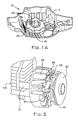
- This clutch mechanism may comprise a set of ratchet teeth 45 on a surface of the hub (see Figs. 1A and 1B), and hinged starter dogs 65, or similar latches, on the flywheel 60 (see Fig. 2). In operation, when the hub 40 is rotated in a forward direction, the ratchet teeth 45 engage with the starter dogs 65, transmitting the rotational force of the hub 40 to the flywheel 60 thus to a crankshaft 70.
- the starter dogs 65 may be spring-loaded or otherwise arranged to operate as a centrifugal clutch, causing the starter dogs to disengage from the ratchet teeth 45 when the flywheel 60 has reached a predetermined rotational velocity, for example. Further, the ratchet teeth 45 may be formed so that the ratchet teeth 45 will only engage with the starter dogs 65 when rotating in a forward direction, thereby allowing disengagement of the hub 40 from the flywheel 60 when the hub 40 reduces its rotational velocity or is rotated in a backward direction.
- the clutch mechanism may comprise moving latches on the hub and ratchet teeth on the flywheel, which would provide for a similar engagement between the hub and flywheel (not shown).
- the engine may use spring-loaded latches or other centrifugal clutch mechanisms to provide for disengagement of the hub 40 from the flywheel 60 when a predetermined rotational velocity has been reached, for example.
- the flywheel 60 is fixed to the crankshaft 70.
- the crankshaft 70 is linked to a piston (not shown), which operates to compress a supplied fuel/air mixture provided to a cylinder when the crankshaft 70 is rotated.
- the operation of the engine after starting is known in the art and will not be detailed herein.
- the starter device 10 may optionally be provided in an engine assembly further comprising a spark system having a sparking mechanism 105 capable of providing a retarded spark.
- the piston In an engine using a traditional starting method without buffering, the piston is rotated directly proportional to the speed at which the rope is pulled by the user.
- the buffering component stores some of the energy being added to the system by the user (and perhaps also some energy feeding back from the engine). This tends to slow down the speed of the crankshaft, and might require faster pulling on the rope to start an engine using a normally timed spark.
- the resulting rotation of the crankshaft 70 driving the piston and compressing the air-fuel mixture in the engine 100 using a normally timed spark may fail to ignite the resulting supply of fuel at an optimum time. This could lead to difficulty in starting the engine, or may even prevent starting in some cases, because the crankshaft 70 is rotating more slowly due to the buffering action.
- a spark By retarding the spark (retarded relative to a similar engine not using a buffering component) using the sparking mechanism 105 during a starting operation, a spark may be supplied at a proper point in time such that the engine 100 is more easily started. Once the engine 100 has started, the sparking mechanism 105 or some other device will adjust the spark to provide a normally timed or advanced spark to accommodate the running engine. It is to be appreciated that each example timing setting may vary dependent upon particulars and parameters associated with the specific engine configuration, etc.
- the hub 40 being a separate component from the pulley 20, may be provided in different materials. Because the hub 40 is exposed to repeated engagement and disengagement with the starter dogs 65, and thereby transmitting a rotational force to the crankshaft 70 through this contact, it may be desirable to construct the hub 40 from a more durable, wear-resistant material, while constructing the pulley 20 from a less durable, more cost efficient material, because the pulley sees lower mechanical stresses.
- the torsion spring 30 is utilized as the buffering component disposed between the pulley 20 and the hub 40.
- the torsion spring thus provides the resilient connection between the hub 40 and pulley 20.
- the torsion spring 30 is adapted to store and transmit energy when the pulley 20 is rotated during startup.
- the starter device may use different buffering components for energy storage, such as a flat spiral spring 130 (shown in Fig. 3B), one or more extension springs 230 (shown in Fig. 3C), multiple spiral springs 330 (shown in Fig. 3D), or multiple torsion springs 430 (shown in Fig. 3E), as additional examples, to be described in more detail later.
- the torsion spring 30 is shown provided at each end with a connecting structure, such as a tail 32, one of which engages with a portion of the pulley 20 and the other of which engages with a portion of the hub 40.
- a connecting structure such as a tail 32, one of which engages with a portion of the pulley 20 and the other of which engages with a portion of the hub 40.
- One tail 32 may be received in a corresponding hole or notch 22 within the pulley 20, shown in Fig. 5.
- the other tail 32 may be received in a corresponding hole or notch 42 within the hub 40, as shown in Fig. 6.
- the torsion spring 30 and the corresponding hub and pulley holes 42, 22 can be adapted such that the torsion spring 30 may be interchangeably installed between the hub 40 and pulley 20 in either direction.
- This design can be used to ease the manufacturing and assembly process, because the spring can then be installed in either direction, allowing a worker (or robot) to more easily position the spring during assembly.
- outermost end coils 33 of the torsion spring 30 are provided with a tapered incline, extending from the tail 32 at each end toward the inner coils of the wire torsion spring 30.
- the hub 40 and pulley 20 can be provided with inclined surfaces 43, 23 (shown in Figs. 5 and 6, respectively) that substantially match the slope of the inclined surfaces of the end coils 33.
- the corresponding inclines thus allow the spring 30 to lie substantially flat against the mating inclined surfaces 43, 23 of the hub 40 and pulley 20.
- the pulley 20 can be provided with a hollow cylindrical post 27, around which an end portion of the torsion spring 30 is disposed.
- the hub 40 may be provided with an annular cage 47, which has a cylindrical outer wall 48 and a cylindrical inner wall (or post) 49, within which an opposite end portion of the spring 30 is disposed.
- the diameter of the spring 30 is reduced, and when the torsion spring 30 is twisted in an expanding direction, the diameter of the spring 30 is increased.
- the cylindrical post 27 and the cylindrical inner wall 49 of the cage serve to limit the minimum diameter of the torsion spring 30 when the spring 30 is twisted in a contracting direction, while the cylindrical outer wall 48 serves to limit the maximum diameter of the spring when the spring 30 is twisted in an expanding direction.
- a spiral spring 130 acts as the buffering component having one end engaged with a hub 140 and an opposite end engaged with a pulley 120.
- the spiral spring 130 is constricted, storing energy and providing the buffering action to assist in providing additional rotational force to the flywheel 60 and crankshaft 70 of Fig. 2 via the hub 140.
- the central portion of the spiral spring 130 is preferably positioned near a central rotational axis of the hub 140 and pulley 120.
- a plurality of extension springs 230 act as buffering components, each spring 230 having one end engaged with a hub 240 and an opposite end engaged with a pulley 220.
- the extension spring 230 extends, storing energy and providing the buffering action to assist in providing the needed rotational force to the flywheel 60 and crankshaft 70 via the hub 240.
- the ends of the extension spring may be attached to the hub 240 and pulley 220 at a distance from a central rotational axis of the hub 240 and pulley 220, so that a satisfactory rotational force may be provided by the extended spring 230 to rotate the hub 240.
- a pair of spiral springs 330 act as buffering components, each spring 330 having one end engaged with a hub 340 and an opposite end engaged with a pulley 320.
- the spiral springs 330 are constricted, storing energy and providing the buffering action to assist in providing the needed rotational force to the flywheel 60 and crankshaft 70 via the hub 340.
- the ends of the spiral springs 330 may be attached to the hub 340 and pulley 320 at some distance from a central rotational axis of the hub 340 and pulley 320, so that a satisfactory rotational force (via a leverage action) may be provided by the spiral springs 330 to rotate the hub 340.
- a pair of torsion springs 430 act as the buffering components, each spring 430 having one end engaged with a hub 440 and an opposite end engaged with a pulley 420.
- the torsion springs 430 are twisted, storing energy and providing the buffering action to assist in providing the needed rotational force to the flywheel 60 and crankshaft 70 via the hub 440.
- the ends of the torsion springs 430 may be attached to the hub 440 and pulley 420 at a distance from a central rotational axis of the hub 440 and pulley 420, so that a satisfactory rotational force may be provided by the torsion springs 430 to rotate the hub 440.
- the pull handle 9 and recoil rope 8 are pulled by a user, thereby unwinding the rope 8, causing the pulley 20 to rotate about the bearing lug 5 in a forward direction and activating the torsion spring 30.
- the forward rotation of the pulley 20 and some portion of the stored energy is transmitted to the hub 40 via the torsion spring 30.
- a retarding spark mechanism 105 provided within the engine assembly 100 causes the spark to be provided with a brief delay to facilitate ignition, easing the starting process.
- the retarding spark mechanism 105 is useful to ensure easy starting. As such, the spark is not provided as soon in the compression cycle.
- any kickback by this process can be absorbed by the buffering component 30, thus buffering this kickback from adversely impacting the person starting the engine 100 and storing the resulting energy.
- This energy absorbed by the buffering component 30 during kickback can then be used to further aid the starting process.
Abstract
Description
- This invention relates generally to a recoil starter for an internal combustion engine.
- More specifically, this application relates to a recoil starter for an internal combustion engine that includes an energy storing mechanism to reduce the pulling forces required to start the engine.
- Conventionally, a recoil starter is used with a manually started internal combustion engine, such as a small two-stroke engine, for example. A rope pulley is rotated by pulling an attached recoil rope that is wound onto the rope pulley, thereby transmitting a rotational force to a crankshaft of the internal combustion engine by way of a ratchet and/or clutch mechanism between the pulley and a flywheel and crankshaft. Rotation of the crankshaft drives a piston and helps provide fuel for ignition. Rotation of the flywheel causes a magneto to power a spark plug, creating a spark for ignition of the engine fuel.
- In operating such a starter mechanism, abrupt changes in the engine torque due to the compression of an air/fuel mixture by the piston and the cylinder within the engine typically result in an uneven and jarring pulling force during starting, and possibly even some kickback forces. These forces can make starting the engine difficult for a user, creating stresses that can even cause an injury.
- To reduce these fluctuations in pulling force, starter mechanisms have been provided which include a second rotating member, coupled to the pulley by way of a buffering component, such as a spring, wherein this second rotating member engages with the engine crankshaft, typically using a ratchet mechanism, for transmission of the rotational force. In such a solution, rotational energy stored within the buffering spring component is used to assist in transmitting a rotational force to the engine crankshaft during periods of higher required torque, thereby dampening the pulling force required by the operator and smoothing the starting operation for the user.
- Despite this modification, drawbacks in the typical buffered recoil starter system remain. The added components necessary to construct such a system result in added expense of material, additional wear considerations, and more cumbersome assembly procedures. Finally, the delayed acceleration of the rotating crankshaft and flywheel can result in difficult starting when a spark is initially provided for ignition.
- Needed is a way to provide a starter device that utilizes a buffering spring to enable starting the engine with a reduced pulling force, while at the same time reducing the inevitable stresses on a spring component to provide greater durability and reliability.
- Additionally, it would be beneficial to provide such a buffered starter device that produces a spark properly timed with the more slowly accelerating crankshaft to ease starting. Further benefits would also be realized by incorporating additional improvements in ease of assembly and durability of the bearing surfaces, while minimizing the use of costly materials and extra components.
- In accordance with one aspect of the present invention, provided is an energy storing starter assembly comprising a pulley, a hub and a buffering component. The buffering component provides a resilient connection between the pulley and the hub, and is designed to store and transmit energy between the pulley and the hub. The ends of the buffering component are further designed to be interchangeable, such that either end of the buffering component may be received by either the hub or the pulley.
- In accordance with another aspect, provided is an energy storing starter assembly comprising a pulley, a hub, and a buffering component. The pulley and hub are each provided with respective inclined support surfaces. The buffering component provides a resilient connection between the pulley and the hub, and is designed to store and transmit energy between the pulley and the hub. The buffering component is provided with a first portion that mates with the support surface of the pulley, and a second portion that mates with the support surface of the hub.
- In accordance with yet another aspect of the present invention, provided is an energy storing starter assembly comprising a pulley, a hub, and a buffering component. The pulley is provided with a center post and is adapted for receiving a pull rope. The hub is provided with a cage and is adapted for releasably engaging an engine. The buffering component provides a resilient connection between the pulley and the hub and is designed to store and transmit energy between the pulley and the hub. One or both of the center post and the cage are adapted for restricting the diameter of the buffering component in one direction when the buffering component is storing a substantial amount of energy, and the cage is adapted for restricting the diameter of the buffering component in another direction when the buffering component is storing a substantial amount of energy.
- In accordance with still another aspect, provided is an energy storing starter assembly comprising a pulley, a hub, and a buffering component. The pulley is provided with a center post and a first inclined surface, and is adapted for receiving a pull rope. The hub is provided with a cage and a second inclined surface, and is adapted for releasably engaging an engine. The buffering component is designed to store and transmit energy between the pulley and the hub. The buffering component is provided with a first portion and a second portion, where each portion is adapted to interchangeably mate with either the first inclined surface of the pulley or the second inclined surface of the hub. The buffering component possesses a diameter that varies with respect to applied loading. One or both of the center post and the cage are adapted for restricting the diameter of the buffering component in one direction when the buffering component is storing a substantial amount of energy, and the cage is adapted for restricting the diameter of the buffering component in another direction when the buffering component is storing a substantial amount of energy.
- In accordance with an additional aspect of the present invention, provided is an energy storing starter assembly comprising a pulley, a hub, and a torsion spring. The pulley is provided with a center post and a first inclined surface, and is adapted for receiving a pull rope. The hub is provided with a cage and a second inclined surface, and is adapted for releasably engaging an engine. The torsion spring provides a resilient connection between the pulley and the hub, and is designed to store and transmit energy between the pulley and the hub. The torsion spring is provided with a first portion, a second portion, a first tail, a second tail, and an inner and outer diameter that vary with respect to applied loading. The first and second portions of the torsion spring are adapted to interchangeably mate with the respective first and second inclined surfaces of the pulley and the hub, such that the first and second portions lie substantially flat against the respective inclined surfaces of the pulley and the hub. Further, the first and second tails of the torsion spring are adapted to be interchangeably received in respective holes of the pulley and the hub. One or both of the center post and the cage are adapted for restricting the inner diameter of the torsion spring when the torsion spring is storing a substantial amount of energy, and the cage is adapted for restricting the outer diameter of the torsion spring when the torsion spring is storing a substantial amount of energy.
- In accordance with a further aspect of the present invention, provided is an engine assembly comprising an energy storing starter assembly and an engine. The energy storing starter assembly includes a pulley, a hub, and a buffering component. The buffering component provides a resilient connection between the pulley and the hub, and is designed to store and transmit energy between the pulley and the hub. The engine optionally includes a spark system adapted to provide a retarded spark during starting to enable a user to more easily start the engine using the energy storing starter assembly.
- In accordance with another aspect of the present invention, provided is an energy storing starter assembly comprising a pulley, a hub, and a buffering component. The buffering component provides a resilient connection between the pulley and the hub, and is designed to store and transmit energy between the pulley and the hub. The hub can be comprised of a more durable material than the pulley.
- In accordance with yet another aspect of the present invention, provided is an energy storing starter assembly comprising a pulley, a hub, and a plurality of buffering components. Each buffering component provides a resilient connection between the pulley and the hub, and is designed to store and transmit energy between the pulley and the hub.
- The foregoing and other features and advantages of the present invention will become apparent to those skilled in the art to which the present invention relates upon reading the following description with reference to the accompanying drawings, in which:
- Fig. 1A is a perspective view of the energy storing starter device according to an embodiment of the invention;
- Fig. 1B is an exploded view of the starter device of Fig. 1A;
- Fig. 2 is a perspective view of the starter device of Fig. 1A, as connected to a two-stroke engine;
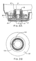
- Fig. 3A is a section view of the starter device of Fig. 1A, wherein a buffering component comprises a torsion spring;
- Fig. 3B is a plan view of a pulley and buffering component of another embodiment of the starter device according to the present invention, wherein the buffering component comprises a flat spiral spring;
- Fig. 3C is a plan view of an additional embodiment of the starter device according to the present invention, wherein the buffering component comprises extension springs;
- Fig. 3D is a plan view of a pulley and buffering component of a further embodiment of the starter device according to the present invention, wherein the buffering component comprises a pair of spiral springs;
- Fig. 3E is a plan view of another embodiment of the starter device according to the present invention, wherein the buffering component comprises a pair of torsion springs;
- Fig. 4 is a perspective view of the torsion spring of the starter device of Fig. 3A;
- Fig. 5 is a perspective view of the pulley of the starter device of Fig. 3A; and
- Fig. 6 is a perspective view of the hub of the starter device of Fig. 3A.
-
- Disclosed are various embodiments of an energy storing recoil starter device including a pulley with a rope, a hub, and a buffering device resiliently connecting the pulley to the hub for storing rotational energy. The device is for aiding a manually started engine, such as a two-stroke engine, for example, which is typically adapted to be disposed in a gas-powered tool, such as a chain saw, for example.
- An example of the energy storing recoil starter device comprises a pulley, one or more buffering components, and a hub. The pulley is manually rotatable using, for example, a pull rope attached thereto. The buffering component provides a resilient connection between the pulley and the hub, and is capable of storing energy generated when the pulley is rotated. The buffering component transmits rotational energy from the pulley to the hub. The hub is releasably engageable with an engine flywheel and crankshaft, for transmitting rotational energy to an engine but capable of being released once the engine is started.
- In an embodiment of the energy storing
recoil starter device 10, shown in Figs. 1A and 1B, the starter device is mounted within afan housing 3. The starter device comprises apulley 20, atorsion spring 30 acting as the buffering component, and ahub 40. Thepulley 20 and thehub 40 thereby resiliently connected together via thespring 30, with the spring acting as an energy storage component to buffer thehub 40 from thepulley 20. - Further referring to Fig. 1B, a
bearing lug 5 is provided on an internal surface of thefan housing 3, upon which thestarter device 10 is mounted. Arecoil spring 7, which may be a spiral spring, for example, is provided with one end connected to thefan housing 3 and an opposite end connected to thepulley 20. Arecoil rope 8 is wound around thepulley 20, with one end of therope 8 connected to a surface of thepulley 20. In the example embodiment, the rope is connected to the pulley using a screw fastener (not shown). A free end of therope 8 is attached to apull handle 9. - The
starter device 10 is further positioned to engage with anengine 100, as shown in Fig. 2. More specifically, thestarter device 10 engages with aflywheel 60, via a clutch or ratchet mechanism as is known in the art. The clutch mechanism rotationally disconnects thestarter device 10 from theflywheel 60 during engine operation but connects it during a starting operation. The clutch mechanism may be engaged at rest, or could be designed to mechanically engage only during the starting operation when thehub 40 is rotating. This clutch mechanism may comprise a set ofratchet teeth 45 on a surface of the hub (see Figs. 1A and 1B), and hingedstarter dogs 65, or similar latches, on the flywheel 60 (see Fig. 2). In operation, when thehub 40 is rotated in a forward direction, theratchet teeth 45 engage with the starter dogs 65, transmitting the rotational force of thehub 40 to theflywheel 60 thus to acrankshaft 70. - The starter dogs 65 may be spring-loaded or otherwise arranged to operate as a centrifugal clutch, causing the starter dogs to disengage from the
ratchet teeth 45 when theflywheel 60 has reached a predetermined rotational velocity, for example. Further, theratchet teeth 45 may be formed so that theratchet teeth 45 will only engage with the starter dogs 65 when rotating in a forward direction, thereby allowing disengagement of thehub 40 from theflywheel 60 when thehub 40 reduces its rotational velocity or is rotated in a backward direction. - Alternatively, the clutch mechanism may comprise moving latches on the hub and ratchet teeth on the flywheel, which would provide for a similar engagement between the hub and flywheel (not shown). Again, the engine may use spring-loaded latches or other centrifugal clutch mechanisms to provide for disengagement of the
hub 40 from theflywheel 60 when a predetermined rotational velocity has been reached, for example. - Traditionally, the
flywheel 60 is fixed to thecrankshaft 70. As is known in the art, thecrankshaft 70 is linked to a piston (not shown), which operates to compress a supplied fuel/air mixture provided to a cylinder when thecrankshaft 70 is rotated. The operation of the engine after starting is known in the art and will not be detailed herein. - It is also contemplated that the
starter device 10 may optionally be provided in an engine assembly further comprising a spark system having a sparking mechanism 105 capable of providing a retarded spark. In an engine using a traditional starting method without buffering, the piston is rotated directly proportional to the speed at which the rope is pulled by the user. However, by adding a buffering component, as the piston compresses the air-fuel mixture, the force opposing the compression increases, and the buffering component stores some of the energy being added to the system by the user (and perhaps also some energy feeding back from the engine). This tends to slow down the speed of the crankshaft, and might require faster pulling on the rope to start an engine using a normally timed spark. - Accordingly, by applying the buffering component in the starting mechanism, the resulting rotation of the
crankshaft 70 driving the piston and compressing the air-fuel mixture in theengine 100 using a normally timed spark may fail to ignite the resulting supply of fuel at an optimum time. This could lead to difficulty in starting the engine, or may even prevent starting in some cases, because thecrankshaft 70 is rotating more slowly due to the buffering action. - By retarding the spark (retarded relative to a similar engine not using a buffering component) using the sparking mechanism 105 during a starting operation, a spark may be supplied at a proper point in time such that the
engine 100 is more easily started. Once theengine 100 has started, the sparking mechanism 105 or some other device will adjust the spark to provide a normally timed or advanced spark to accommodate the running engine. It is to be appreciated that each example timing setting may vary dependent upon particulars and parameters associated with the specific engine configuration, etc. - It is further contemplated that the
hub 40, being a separate component from thepulley 20, may be provided in different materials. Because thehub 40 is exposed to repeated engagement and disengagement with the starter dogs 65, and thereby transmitting a rotational force to thecrankshaft 70 through this contact, it may be desirable to construct thehub 40 from a more durable, wear-resistant material, while constructing thepulley 20 from a less durable, more cost efficient material, because the pulley sees lower mechanical stresses. - In the embodiment of Figs. 1A, 1B, and 3A, discussed briefly above, the
torsion spring 30 is utilized as the buffering component disposed between thepulley 20 and thehub 40. The torsion spring thus provides the resilient connection between thehub 40 andpulley 20. Thetorsion spring 30 is adapted to store and transmit energy when thepulley 20 is rotated during startup. In other embodiments of the invention, the starter device may use different buffering components for energy storage, such as a flat spiral spring 130 (shown in Fig. 3B), one or more extension springs 230 (shown in Fig. 3C), multiple spiral springs 330 (shown in Fig. 3D), or multiple torsion springs 430 (shown in Fig. 3E), as additional examples, to be described in more detail later. - Referring to the
starter device 10 of Fig. 1B, in Figs. 3A and 4, thetorsion spring 30 is shown provided at each end with a connecting structure, such as atail 32, one of which engages with a portion of thepulley 20 and the other of which engages with a portion of thehub 40. Onetail 32 may be received in a corresponding hole or notch 22 within thepulley 20, shown in Fig. 5. Likewise, theother tail 32 may be received in a corresponding hole or notch 42 within thehub 40, as shown in Fig. 6. - The
torsion spring 30 and the corresponding hub and pulley holes 42, 22 can be adapted such that thetorsion spring 30 may be interchangeably installed between thehub 40 andpulley 20 in either direction. This design can be used to ease the manufacturing and assembly process, because the spring can then be installed in either direction, allowing a worker (or robot) to more easily position the spring during assembly. - As shown in Fig. 4, outermost end coils 33 of the
torsion spring 30 are provided with a tapered incline, extending from thetail 32 at each end toward the inner coils of thewire torsion spring 30. To provide a secure fit and additional support for thetorsion spring 30, thehub 40 andpulley 20 can be provided withinclined surfaces 43, 23 (shown in Figs. 5 and 6, respectively) that substantially match the slope of the inclined surfaces of the end coils 33. The corresponding inclines thus allow thespring 30 to lie substantially flat against the mating inclined surfaces 43, 23 of thehub 40 andpulley 20. By making the inclines of the twosurfaces torsion spring 30 can be maintained. - As further shown in Figs. 3A and 5, the
pulley 20 can be provided with a hollow cylindrical post 27, around which an end portion of thetorsion spring 30 is disposed. Additionally, as shown in Figs. 3A and 6, thehub 40 may be provided with anannular cage 47, which has a cylindricalouter wall 48 and a cylindrical inner wall (or post) 49, within which an opposite end portion of thespring 30 is disposed. - Typically, when the
torsion spring 30 is twisted in a contracting direction, the diameter of thespring 30 is reduced, and when thetorsion spring 30 is twisted in an expanding direction, the diameter of thespring 30 is increased. The cylindrical post 27 and the cylindricalinner wall 49 of the cage serve to limit the minimum diameter of thetorsion spring 30 when thespring 30 is twisted in a contracting direction, while the cylindricalouter wall 48 serves to limit the maximum diameter of the spring when thespring 30 is twisted in an expanding direction. - These limitations to the spring diameter effectively limit the spring deflection during operation of the
starter device 10 and help control the buffering action of the starter device as thespring 30 stores energy in one direction or the other, for example. - In an alternative embodiment, as shown in Fig. 3B, for example, a
spiral spring 130 acts as the buffering component having one end engaged with ahub 140 and an opposite end engaged with apulley 120. When thepulley 120 is rotated during start-up, thespiral spring 130 is constricted, storing energy and providing the buffering action to assist in providing additional rotational force to theflywheel 60 andcrankshaft 70 of Fig. 2 via thehub 140. The central portion of thespiral spring 130 is preferably positioned near a central rotational axis of thehub 140 andpulley 120. - In another alternative embodiment, as shown in Fig. 3C, for example, a plurality of extension springs 230 act as buffering components, each
spring 230 having one end engaged with ahub 240 and an opposite end engaged with apulley 220. When thepulley 220 is rotated during startup, theextension spring 230 extends, storing energy and providing the buffering action to assist in providing the needed rotational force to theflywheel 60 andcrankshaft 70 via thehub 240. The ends of the extension spring may be attached to thehub 240 andpulley 220 at a distance from a central rotational axis of thehub 240 andpulley 220, so that a satisfactory rotational force may be provided by theextended spring 230 to rotate thehub 240. - In still another alternative embodiment, as shown in Fig. 3D, for example, a pair of spiral springs 330 act as buffering components, each
spring 330 having one end engaged with ahub 340 and an opposite end engaged with apulley 320. When thepulley 320 is rotated during startup, the spiral springs 330 are constricted, storing energy and providing the buffering action to assist in providing the needed rotational force to theflywheel 60 andcrankshaft 70 via thehub 340. The ends of the spiral springs 330 may be attached to thehub 340 andpulley 320 at some distance from a central rotational axis of thehub 340 andpulley 320, so that a satisfactory rotational force (via a leverage action) may be provided by the spiral springs 330 to rotate thehub 340. - In yet another alternative embodiment, as shown in Fig. 3E, for example, a pair of torsion springs 430 act as the buffering components, each
spring 430 having one end engaged with ahub 440 and an opposite end engaged with apulley 420. When thepulley 420 is rotated during startup, the torsion springs 430 are twisted, storing energy and providing the buffering action to assist in providing the needed rotational force to theflywheel 60 andcrankshaft 70 via thehub 440. The ends of the torsion springs 430 may be attached to thehub 440 andpulley 420 at a distance from a central rotational axis of thehub 440 andpulley 420, so that a satisfactory rotational force may be provided by the torsion springs 430 to rotate thehub 440. - In operating the example embodiment of the
starter device 10 as shown in Figs. 1A and 1B, thepull handle 9 andrecoil rope 8 are pulled by a user, thereby unwinding therope 8, causing thepulley 20 to rotate about thebearing lug 5 in a forward direction and activating thetorsion spring 30. The forward rotation of thepulley 20 and some portion of the stored energy is transmitted to thehub 40 via thetorsion spring 30. - As the
hub 40 is rotated, theratchet teeth 45 engage with a pair of hingedstarter dogs 65 attached to anengine flywheel 60, thereby translating the rotational motion of thestarter device 10 to theflywheel 60, which is fixed to thecrankshaft 70 of theengine 100. During this operation, energy is stored in the spring, providing the buffering action. In a possible embodiment of thestarter device 10, a retarding spark mechanism 105 provided within theengine assembly 100 causes the spark to be provided with a brief delay to facilitate ignition, easing the starting process. - As the crankshaft is further rotated, compressing the fuel-air mixture in the piston, an opposing force increases, further stressing the torsion spring and causing further energy to be stored. As the piston reaches and then passes top dead center (TDC), the stored energy in the
torsion spring 30 is at least partially released, thus increasing the speed of the rotation, which can make further pulling easier for the next compression. The act of storing energy in thetorsion spring 30 smoothes out the pulling process for the user, absorbing energy at moments of peak opposition due to compression forces in the cylinder. - It is to be appreciated that because the energy storage action tends to slow down the piston speed at the time of increasing compression (compared to the action with no buffering present), the retarding spark mechanism 105 is useful to ensure easy starting. As such, the spark is not provided as soon in the compression cycle.
- Further, as the
engine 100 is started and the piston compresses the fuel-air mixture in the cylinder, any kickback by this process can be absorbed by thebuffering component 30, thus buffering this kickback from adversely impacting the person starting theengine 100 and storing the resulting energy. This energy absorbed by thebuffering component 30 during kickback can then be used to further aid the starting process. - The alternative embodiments work in a manner similar to that described above, with the primary differences, if any, being in the manner in which energy is stored in the spring and transmitted from the corresponding pulley to the hub.
- The invention has been described hereinabove using specific examples; however, it will be understood by those skilled in the art that various alternatives may be used and equivalents may be substituted for elements or steps described herein, without deviating from the scope of the invention. Modifications may be necessary to adapt the invention to a particular situation or to particular needs without departing from the scope of the invention. It is intended that the invention not be limited to the particular implementation described herein, but that the claims be given their broadest interpretation to cover all embodiments, literal or equivalent, covered thereby.
Claims (35)
- An energy storing starter assembly comprising:a pulley;a hub; anda buffering component having a first end and a second end, said buffering component for resiliently connecting said pulley to said hub, wherein:said buffering component is for storing and transmitting energy between said pulley and said hub, and said first and said second ends are each adapted to be received in a respective one of said pulley and said hub and are interchangeable to be received in the other of said pulley and said hub.
- The starter assembly of claim 1, wherein said buffering component includes a torsion spring.
- The starter assembly of claim 2, wherein said first end has a first tail to be received by said respective one of said pulley and said hub, and said second end has a second tail to be received by the other of said pulley and said hub.
- The starter assembly of claim 3, wherein said torsion spring includes a coil of wire, said first and second tails have outward extensions of said wire extending in opposite directions, and said outward extensions for being respectively received by holes in said one and the other of said pulley and said hub.
- The starter assembly of claim 4, wherein said pulley includes a first support surface having an incline, said hub includes a second support surface having said incline, said buffering component includes a first portion and a second portion for mating with a respective one of said first support surface and said second support surface and being interchangeable for mating with the other said first support surface and said second support surface, and said first and second portions lie substantially flat against said respective first and said second support surfaces.
- The starter assembly of claim 4, wherein said torsion spring has an inner diameter and an outer diameter that vary with respect to applied loading; said pulley has a center post; said hub has a cage; one or both of said center post and said cage are adapted for restricting said inner diameter of said torsion spring when said buffering component is storing a substantial amount of energy, and said cage is adapted for restricting said outer diameter of said torsion spring when said buffering component is storing said substantial or another substantial amount of energy.
- An engine assembly comprising an energy storing starter assembly according to claim 4 and an engine including a spark system, said engine being releasably engaged with said hub for receiving rotational energy, and said engine spark system being adapted for providing a retarded spark during starting to enable a user to more easily start said engine using said energy storing starter assembly.
- The starter assembly of claim 1, wherein said buffering component has a diameter that varies with respect to applied loading; said pulley has a center post; said hub has a cage, one or both of said center post and said cage are adapted for restricting said diameter of said buffering component in at least one direction when said buffering component is storing a substantial amount of energy, and said cage is adapted for restricting said diameter of said buffering component in another direction when said buffering component is storing said substantial or another substantial amount of energy.
- The starter assembly of claim 1, wherein said pulley includes a first support surface having an incline, said hub includes a second support surface having said incline, said buffering component has a first portion and a second portion for mating with a respective one of said first support surface and said second support surface and are interchangeable to mate with the other of said first support surface and said second support surface, and said first and said second portions lie substantially flat against said respective first and said second support surfaces.
- The starter assembly of claim 9, wherein said buffering component has a diameter that varies with respect to applied loading; said pulley has a center post; said hub has a cage; one or both of said center post and said hub are adapted for restricting said diameter of said buffering component in at least one direction when said buffering component is storing a substantial amount of energy, and said cage is adapted for restricting said diameter of said buffering component in another direction when said buffering component is storing said substantial or another substantial amount of energy.
- An engine assembly comprising an energy storing starter assembly according to claim 10, and an engine including a spark system, said engine being releasably engaged with said hub for receiving rotational energy, and said engine spark system being adapted for providing a retarded spark during starting to enable a user to more easily start said engine using said energy storing starter assembly.
- An engine assembly comprising an energy storing starter assembly according to claim 9 and an engine including a spark system, said engine being releasably engaged with said hub for receiving rotational energy, and said engine spark system being adapted for providing a retarded spark during starting to enable a user to more easily start said engine using said energy storing starter assembly.
- An engine assembly comprising an energy storing starter assembly according to claim 8 and an engine including a spark system, said engine being releasably engaged with said hub for receiving rotational energy, and said engine spark system being adapted for providing a retarded spark during starting to enable a user to more easily start said engine using said energy storing starter assembly.
- An engine assembly comprising an energy storing starter assembly according to claim 1 and an engine including a spark system, said engine being releasably engaged with said hub for receiving rotational energy, and said engine spark system being adapted for providing a retarded spark during starting to enable a user to more easily start said engine using said energy storing starter assembly.
- An energy storing starter assembly comprising:a pulley having a first support surface having a first incline;a hub having a second support surface having said first or a second incline; anda buffering component having a first portion for mating with said first support surface and a second portion for mating with said second support surface, said buffering component for resiliently connecting said pulley to said hub, whereinsaid buffering component is for storing and transmitting energy between said pulley and said hub.
- The starter assembly of claim 15, wherein said first and said second portions of said buffering component lie substantially flat against said first and said second support surfaces, respectively.
- The starter assembly of claim 15, wherein said buffering component includes a torsion spring having of a coil of wire, and wherein said first portion is formed from said wire and said second portion is formed from said wire.
- The starter assembly of claim 17, wherein said torsion spring has an inner and an outer diameter that vary with respect to applied loading, said pulley has a center post; said hub has a cage; one or both of said center post and said cage are adapted for restricting said inner diameter of said torsion spring when said buffering component is storing a substantial amount of energy, and said cage is adapted for restricting an outer diameter of said torsion spring when said buffering component is storing said substantial or another substantial amount of energy.
- The starter assembly of claim 15, wherein said buffering component has a diameter that varies with respect to applied loading, said pulley has a center post; said hub has a cage; one or both of said center post and said cage are adapted for restricting said diameter of said buffering component in one direction when said buffering component is storing a substantial amount of energy, and said cage is adapted for restricting said diameter of said buffering component in another direction when said buffering component is storing said substantial or another substantial amount of energy.
- An engine assembly comprising an energy storing starter assembly according to claim 19 and an engine including a spark system, said engine being releasably engaged with said hub for receiving rotational energy, and said engine spark system being adapted for providing a retarded spark during starting to enable a user to more easily start said engine using said energy storing starter assembly.
- An engine assembly comprising an energy storing starter assembly according to claim 15 and an engine including a spark system, said engine being releasably engaged with said hub for receiving rotational energy, and said engine spark system being adapted for providing a retarded spark during starting to enable a user to more easily start said engine using said energy storing starter assembly.
- An energy storing starter assembly comprising:a pulley having a center post and adapted for receiving a pull rope;a hub having a cage and adapted for releasably engaging an engine; anda buffering component for resiliently connecting said pulley to said hub and for storing and transmitting energy between said pulley and said hub and having a diameter that varies with respect to applied loading, whereinone or both of said center post and said cage are adapted for restricting said diameter of said buffering component in one direction when said buffering component is storing a substantial amount of energy, and said cage is adapted for restricting said diameter of said buffering component in another direction when said buffering component is storing said substantial or another substantial amount of energy.
- The starter assembly of claim 22, wherein said buffering component includes a torsion spring having a first end and a second end.
- The starter assembly of claim 23, wherein said first end has a first tail to be received in a respective one of said pulley and said hub and a second tail to be received in the other of said pulley and said hub.
- An engine assembly comprising an energy storing starter assembly according to claim 22 and an engine including a spark system, said engine being releasably engaged with said hub for receiving rotational energy, and said engine spark system being adapted for providing a retarded spark during starting to enable a user to more easily start said engine using said energy storing starter assembly.
- An energy storing starter assembly comprising:wherein one or both of said center post and said cage are adapted for restricting said diameter of said buffering component in one direction when said buffering component is storing a substantial amount of energy, and whereina pulley having a center post and a first surface at a first incline and adapted for receiving a pull rope;a hub having a cage and a second surface at said first or a second incline and adapted for releasably engaging an engine; anda buffering component for storing and transmitting energy from said pulley to said hub, said buffering component including:a first portion;a second portion, anda diameter that varies with respect to applied loading, whereinsaid first portion and said second portion are adapted for mating with a respective one of said first surface and said second surface, and are interchangeable for mating with the other of said first surface and said second surface, such that said first portion and said second portion lie substantially flat against said respective first surface and said second surface;
said cage is adapted for restricting said diameter of said buffering component in another direction when said buffering component is storing said substantial or another substantial amount of energy. - An engine assembly comprising an energy storing starter assembly and said engine both according to claim 26, wherein said engine includes a spark system, said engine being releasably engaged with said hub for receiving rotational energy from said hub, and said engine spark system is adapted for providing a retarded spark during starting to enable a user to more easily start said engine using said energy storing starter assembly.
- An energy storing starter assembly comprising:a pulley having a center post and a first surface at an incline and adapted for receiving a pull rope;a hub having a cage and a second surface at said incline and adapted for releasably engaging an engine; anda torsion spring for resiliently connecting said pulley to said hub and for storing and transmitting energy between said pulley and said hub, said torsion spring including a first portion, a second portion, a first tail, a second tail, and an inner and an outer diameter that vary with respect to applied loading, wherein said first portion and said second portion are adapted for mating with a respective one of said first surface and said second surface, and are interchangeable for mating with the other of said first surface and said second surface, such that said first portion and said second portion lie substantially flat against said respective first surface and said second surface, said first and said second tails are each adapted to be received in a hole in a respective one of said pulley and said hub and are interchangeable to be received in a hole in the other of said pulley and said hub; one or both of said center post and said cage are adapted for restricting said inner diameter of said torsion spring when said torsion spring is storing a substantial amount of energy, and said cage is adapted for restricting said outer diameter of said torsion spring when said torsion spring is storing said substantial or another substantial amount of energy.
- The starter assembly of claim 28, wherein said torsion spring further has a first tail and a second tail, wherein said first tail and said second tail are adapted to be received by a respective one of said pulley and said hub and are interchangeable to be received by the other of said pulley and said hub.
- An engine assembly comprising an energy storing starter assembly and said engine both according to claim 28, said engine includes a spark system, said engine being releasably engaged with said hub for receiving rotational energy from said hub, and said engine spark system is adapted for providing a retarded spark during starting to enable a user to more easily start said engine using said energy storing starter assembly.
- An engine assembly comprising:wherein said engine spark system is adapted for providing a retarded spark during starting to enable a user to more easily start said engine using said energy storing starter assembly.an energy storing starter assembly including:wherein said buffering component is for storing and transmitting energy from said pulley to said hub; anda pulley;a hub; anda buffering component for resiliently connecting said pulley to said hub;an engine including a spark system, said engine being releasably engaged with said hub for receiving rotational energy,
- An energy storing starter assembly comprising:wherein said buffering component is for storing and transmitting energy from said pulley to said hub, and said hub is comprised of a more durable material than said pulley.a pulley;a hub; anda buffering component for resiliently connecting said pulley to said hub;
- An energy storing starter assembly comprising:wherein said buffering components are for storing and transmitting energy between said pulley and said hub.a pulley;a hub; anda plurality of buffering components, each for resiliently connecting said pulley to said hub;
- The starter assembly of claim 33, wherein said buffering components each have a first end and a second end, said first ends being received in said pulley at a distance from a central rotational axis of said pulley.
- The starter assembly of claim 34, wherein said second ends are received in said hub at said distance or another distance from the central rotational axis of said pulley and said hub.
Applications Claiming Priority (2)
| Application Number | Priority Date | Filing Date | Title |
|---|---|---|---|
| US846224 | 1992-03-04 | ||
| US10/846,224 US7191752B2 (en) | 2004-05-14 | 2004-05-14 | Energy storing starter assembly |
Publications (3)
| Publication Number | Publication Date |
|---|---|
| EP1596060A2 true EP1596060A2 (en) | 2005-11-16 |
| EP1596060A3 EP1596060A3 (en) | 2009-09-09 |
| EP1596060B1 EP1596060B1 (en) | 2012-08-08 |
Family
ID=34943238
Family Applications (1)
| Application Number | Title | Priority Date | Filing Date |
|---|---|---|---|
| EP05445028A Not-in-force EP1596060B1 (en) | 2004-05-14 | 2005-05-04 | Energy storing starter assembly |
Country Status (6)
| Country | Link |
|---|---|
| US (1) | US7191752B2 (en) |
| EP (1) | EP1596060B1 (en) |
| JP (1) | JP2005325833A (en) |
| CN (1) | CN1696494A (en) |
| CA (1) | CA2488711C (en) |
| TW (1) | TWI257453B (en) |
Cited By (3)
| Publication number | Priority date | Publication date | Assignee | Title |
|---|---|---|---|---|
| EP1798411A2 (en) * | 2005-12-14 | 2007-06-20 | Starting Industry Co., Ltd. | Recoil starter |
| WO2012008980A1 (en) * | 2010-07-14 | 2012-01-19 | Husqvarna Forestry Products N.A., Inc | Starting device for an internal combustion engine |
| EP2466117A1 (en) * | 2010-11-30 | 2012-06-20 | Makita Corporation | Starter device for a combustion engine |
Families Citing this family (22)
| Publication number | Priority date | Publication date | Assignee | Title |
|---|---|---|---|---|
| JP4064961B2 (en) * | 2004-10-06 | 2008-03-19 | スターテング工業株式会社 | Recoil starter |
| JP4376193B2 (en) * | 2005-02-08 | 2009-12-02 | ハスクバーナ・ゼノア株式会社 | Power transmission mechanism between engine starter and engine |
| US7267091B2 (en) * | 2005-04-27 | 2007-09-11 | Husqvarna Outdoor Products Inc. | Dynamic effortless pull starting |
| US7162988B1 (en) * | 2006-07-19 | 2007-01-16 | Hsin-Chih Chung Lee | Power-saving activation device |
| US7574988B1 (en) | 2008-03-17 | 2009-08-18 | Briggs And Stratton Corporation | Engine starter assembly |
| DE202008015755U1 (en) * | 2008-11-27 | 2010-04-15 | Dolmar Gmbh | starter device |
| US8291879B2 (en) * | 2008-12-03 | 2012-10-23 | Techtronic Outdoor Products Technology Limited | Recoil starter system |
| US8132553B2 (en) * | 2008-12-03 | 2012-03-13 | Techtronic Outdoor Products Technology Limited | Recoil starter system |
| JP5261797B2 (en) * | 2009-02-17 | 2013-08-14 | スターテング工業株式会社 | Recoil starter |
| US7886709B2 (en) * | 2009-05-29 | 2011-02-15 | GM Global Technology Operations LLC | Spring start for a vehicle engine |
| EP2290222B1 (en) * | 2009-08-25 | 2014-11-12 | Makita Corporation | Starter device for combustion engine |
| US8656882B2 (en) * | 2010-01-27 | 2014-02-25 | Kokusan Denki Co., Ltd. | Engine ignition control device |
| US8689942B2 (en) | 2010-11-24 | 2014-04-08 | Raytheon Company | Energy storage and release system |
| DE202011000610U1 (en) * | 2011-03-17 | 2012-06-18 | Makita Corporation | Starting device for at least one internal combustion engine, in particular cable pull start device |
| WO2013015779A2 (en) * | 2011-07-25 | 2013-01-31 | Husqvarna Consumer Outdoor Products Na, Inc. | Starting system for an engine |
| JP6046895B2 (en) * | 2012-01-25 | 2016-12-21 | スターテング工業株式会社 | Recoil starter |
| CN102588181A (en) * | 2012-03-13 | 2012-07-18 | 山东华盛农业药械有限责任公司 | Recoil starter |
| JP6029473B2 (en) * | 2013-01-07 | 2016-11-24 | スターテング工業株式会社 | Recoil starter |
| CN103244331A (en) * | 2013-04-07 | 2013-08-14 | 山东华盛农业药械有限责任公司 | Buffer starter of gasoline engine |
| JP7391357B2 (en) * | 2019-09-19 | 2023-12-05 | スターテング工業株式会社 | recoil starter |
| US11319915B2 (en) | 2020-06-11 | 2022-05-03 | Kohler Co. | Engine system, and method of starting the engine |
| JP2022010603A (en) * | 2020-06-29 | 2022-01-17 | スターテング工業株式会社 | Engine starting device |
Citations (12)
| Publication number | Priority date | Publication date | Assignee | Title |
|---|---|---|---|---|
| US4848288A (en) * | 1987-05-19 | 1989-07-18 | Starting Industry Co., Ltd. | Starting apparatus |
| GB2218470A (en) * | 1988-05-11 | 1989-11-15 | Hatz Motoren | Pull cord starter for i.c.engines |
| EP0364118B1 (en) * | 1988-10-14 | 1993-01-20 | Yanmar Diesel Engine Co. Limited | Starting apparatus for engines |
| US5287832A (en) * | 1991-10-26 | 1994-02-22 | Andreas Stihl | Starting device for an internal combustion engine |
| EP0623743A1 (en) * | 1993-05-07 | 1994-11-09 | Nikkari Co., Ltd. | Power storage type recoil starter |
| US6314938B1 (en) * | 1998-10-26 | 2001-11-13 | Deere & Company | Starting system for spark ignition engine |
| US20020174848A1 (en) * | 2001-05-25 | 2002-11-28 | Starting Industrial Co., Ltd. | Recoil starter |
| US20020185352A1 (en) * | 2001-06-11 | 2002-12-12 | Markus Husges To Andreas Stihl Ag & Co. | Starter device for an internal combustion engine |
| JP2003239831A (en) * | 2002-02-15 | 2003-08-27 | Showa Kiki Kogyo Kk | Force accumulation type starter device |
| JP2003322075A (en) * | 2002-04-30 | 2003-11-14 | Shin Daiwa Kogyo Co Ltd | Starter device |
| EP1365143A1 (en) * | 2002-05-20 | 2003-11-26 | Starting Industrial Co., Ltd. | Recoil starter |
| EP1394404A2 (en) * | 2002-08-29 | 2004-03-03 | Starting Industrial Co., Ltd. | Recoil starter |
Family Cites Families (55)
| Publication number | Priority date | Publication date | Assignee | Title |
|---|---|---|---|---|
| US1116370A (en) * | 1913-12-03 | 1914-11-10 | Vincent Bendix | Starter for engines. |
| US3010443A (en) * | 1959-03-19 | 1961-11-28 | Garland E Lyvers | Engine starting device |
| US3306277A (en) * | 1964-10-23 | 1967-02-28 | Mcculloch Corp | Spring starter for internal combustion engines |
| US3861374A (en) * | 1971-05-05 | 1975-01-21 | Mccullock Corp | Lightweight chain saw with engine restarting system and method and apparatus for restarting a warm internal combustion engine |
| US4019490A (en) * | 1975-05-09 | 1977-04-26 | Tecumseh Products Company | Pull-rope recoil starter |
| US4068644A (en) * | 1976-06-25 | 1978-01-17 | Colt Industries Operating Corporation | Rewind starter pulley assembly |
| US4157083A (en) * | 1977-06-06 | 1979-06-05 | Outboard Marine Corporation | Combination manual and power starter for engines |
| AT377832B (en) * | 1978-12-04 | 1985-05-10 | Bombardier Rotax Gmbh | RETURN STARTER FOR COMBUSTION ENGINES |
| JPS5932743Y2 (en) * | 1980-11-28 | 1984-09-13 | 今在家精工株式会社 | spring clutch |
| AT385092B (en) * | 1981-02-27 | 1988-02-10 | Bombardier Rotax Gmbh | RETURN STARTER FOR INTERNAL COMBUSTION ENGINE |
| SE435418B (en) * | 1981-06-16 | 1984-09-24 | Electrolux Ab | COMBUSTION ENGINE WITH WEAVAX BEARINGS |
| US4492190A (en) * | 1983-04-20 | 1985-01-08 | Eaton Stamping Company | Recoil starter |
| JPS6021037U (en) * | 1983-07-22 | 1985-02-13 | 日本電気株式会社 | one way clutch |
| US4582030A (en) * | 1984-03-02 | 1986-04-15 | Tecumseh Products Company | Mounting recoil starter |
| JPS61135981A (en) * | 1984-12-03 | 1986-06-23 | Sutaatengu Kogyo Kk | Recoil starter |
| SE444208B (en) * | 1984-08-23 | 1986-03-24 | Electrolux Ab | Hand starter |
| SE450029B (en) * | 1985-02-27 | 1987-06-01 | Electrolux Ab | Torque limiting device in internal combustion engine with magnetic ignition system |
| US5159845A (en) * | 1987-11-27 | 1992-11-03 | Komatsu Zenoah Kabushiki Kaisha | Engine starter |
| US4970998A (en) * | 1989-05-26 | 1990-11-20 | Eaton Indiana, Inc. | Offset starter pawl |
| SE8902691L (en) * | 1989-08-08 | 1991-02-09 | Electrolux Ab | Hand starter |
| SE501795C2 (en) * | 1990-12-12 | 1995-05-15 | Electrolux Ab | starter |
| SE501998C2 (en) * | 1991-10-14 | 1995-07-10 | Electrolux Ab | Heat and vibration dampening device at a carburetor |
| US5370008A (en) * | 1991-10-28 | 1994-12-06 | Landolt; Gary A. | Starter coupler for an internal combustion engine |
| JP3073836B2 (en) | 1992-07-02 | 2000-08-07 | メルク・ジヤパン株式会社 | Pearlescent pigment having discoloration resistance and method for producing the same |
| SE503356C2 (en) * | 1994-09-02 | 1996-05-28 | Electrolux Ab | Incinerator starter |
| US5676103A (en) * | 1995-05-09 | 1997-10-14 | Starting Industrial Co., Ltd | Recoil starter |
| US5715783A (en) * | 1996-04-30 | 1998-02-10 | Starting Industrial Co., Ltd. | Recoil starter |
| JPH11117835A (en) * | 1997-10-13 | 1999-04-27 | Sanshin Ind Co Ltd | Abnormal-sound suppressing structure of outboard engine recoil starter |
| US6199529B1 (en) * | 1998-03-31 | 2001-03-13 | Honda Giken Kogyo Kabushiki Kaisha And Starting Industrial Co., Ltd. | Engine starting apparatus |
| SE9801708L (en) * | 1998-05-14 | 1999-01-25 | Jerzy Janczak | Operating device |
| CN1143058C (en) * | 1999-08-06 | 2004-03-24 | 本田技研工业株式会社 | Starter for engine |
| US6508220B1 (en) | 1999-08-25 | 2003-01-21 | Kioritz Corporation | Starter |
| JP3905689B2 (en) * | 2000-05-24 | 2007-04-18 | 株式会社共立 | Recoil starter device |
| JP4301480B2 (en) * | 2000-11-06 | 2009-07-22 | スターテング工業株式会社 | Recoil starter |
| US6739303B2 (en) * | 2001-07-18 | 2004-05-25 | Starting Industrial Co., Ltd. | Recoil starter |
| JP4119632B2 (en) * | 2001-09-26 | 2008-07-16 | 株式会社共立 | Recoil starter device for back load type power work equipment |
| JP2003148305A (en) * | 2001-11-16 | 2003-05-21 | Starting Ind Co Ltd | Recoil starter |
| JP2003222064A (en) * | 2002-01-31 | 2003-08-08 | Kioritz Corp | Recoil starter for knapsack type power-machine |
| JP2003343399A (en) * | 2002-05-27 | 2003-12-03 | Kioritz Corp | Recoil starter device for shouldering type power working machine |
| US6572427B1 (en) * | 2002-06-05 | 2003-06-03 | Arko Development Limited | Bubble generating assembly |
| US6959680B2 (en) * | 2002-07-24 | 2005-11-01 | Starting Industrial Co., Ltd. | Recoil starter |
| JP3812896B2 (en) * | 2002-08-29 | 2006-08-23 | スターテング工業株式会社 | Recoil starter |
| US6782863B2 (en) * | 2002-10-08 | 2004-08-31 | Mtd Products Inc. | Spring release starter |
| JP4014998B2 (en) * | 2002-10-21 | 2007-11-28 | スターテング工業株式会社 | Recoil starter |
| JP4346922B2 (en) * | 2002-10-21 | 2009-10-21 | スターテング工業株式会社 | Recoil starter |
| DE20301182U1 (en) * | 2003-01-29 | 2004-06-09 | Dolmar Gmbh | Starting device for an internal combustion engine |
| US20040149249A1 (en) * | 2003-01-29 | 2004-08-05 | Olaf Kruse | Starting device for internal combustion engine |
| US6959681B2 (en) | 2003-02-19 | 2005-11-01 | Kyodo Rubber Industries Co., Ltd. | Engine starter |
| JP3878564B2 (en) * | 2003-02-28 | 2007-02-07 | スターテング工業株式会社 | Accumulated recoil starter |
| JP2004360494A (en) * | 2003-06-02 | 2004-12-24 | Starting Ind Co Ltd | Recoil starter |
| DE10341462B4 (en) * | 2003-09-09 | 2012-11-29 | Andreas Stihl Ag & Co. Kg | Starting device for an internal combustion engine |
| JP4349486B2 (en) * | 2004-03-09 | 2009-10-21 | 株式会社協同 | Engine starter device |
| US20060027201A1 (en) * | 2004-08-09 | 2006-02-09 | Ryou Ono | Engine starter |
| JP4064961B2 (en) * | 2004-10-06 | 2008-03-19 | スターテング工業株式会社 | Recoil starter |
| US7140341B2 (en) * | 2005-04-14 | 2006-11-28 | Aktiebolaget Electrolux | Energy storing starter assembly |
-
2004
- 2004-05-14 US US10/846,224 patent/US7191752B2/en active Active
- 2004-11-23 TW TW093135950A patent/TWI257453B/en not_active IP Right Cessation
- 2004-11-30 CA CA002488711A patent/CA2488711C/en active Active
-
2005
- 2005-01-31 JP JP2005022488A patent/JP2005325833A/en active Pending
- 2005-04-15 CN CN200510064382.5A patent/CN1696494A/en active Pending
- 2005-05-04 EP EP05445028A patent/EP1596060B1/en not_active Not-in-force
Patent Citations (12)
| Publication number | Priority date | Publication date | Assignee | Title |
|---|---|---|---|---|
| US4848288A (en) * | 1987-05-19 | 1989-07-18 | Starting Industry Co., Ltd. | Starting apparatus |
| GB2218470A (en) * | 1988-05-11 | 1989-11-15 | Hatz Motoren | Pull cord starter for i.c.engines |
| EP0364118B1 (en) * | 1988-10-14 | 1993-01-20 | Yanmar Diesel Engine Co. Limited | Starting apparatus for engines |
| US5287832A (en) * | 1991-10-26 | 1994-02-22 | Andreas Stihl | Starting device for an internal combustion engine |
| EP0623743A1 (en) * | 1993-05-07 | 1994-11-09 | Nikkari Co., Ltd. | Power storage type recoil starter |
| US6314938B1 (en) * | 1998-10-26 | 2001-11-13 | Deere & Company | Starting system for spark ignition engine |
| US20020174848A1 (en) * | 2001-05-25 | 2002-11-28 | Starting Industrial Co., Ltd. | Recoil starter |
| US20020185352A1 (en) * | 2001-06-11 | 2002-12-12 | Markus Husges To Andreas Stihl Ag & Co. | Starter device for an internal combustion engine |
| JP2003239831A (en) * | 2002-02-15 | 2003-08-27 | Showa Kiki Kogyo Kk | Force accumulation type starter device |
| JP2003322075A (en) * | 2002-04-30 | 2003-11-14 | Shin Daiwa Kogyo Co Ltd | Starter device |
| EP1365143A1 (en) * | 2002-05-20 | 2003-11-26 | Starting Industrial Co., Ltd. | Recoil starter |
| EP1394404A2 (en) * | 2002-08-29 | 2004-03-03 | Starting Industrial Co., Ltd. | Recoil starter |
Cited By (6)
| Publication number | Priority date | Publication date | Assignee | Title |
|---|---|---|---|---|
| EP1798411A2 (en) * | 2005-12-14 | 2007-06-20 | Starting Industry Co., Ltd. | Recoil starter |
| EP1798411A3 (en) * | 2005-12-14 | 2009-03-18 | Starting Industrial Co., Ltd. | Recoil starter |
| WO2012008980A1 (en) * | 2010-07-14 | 2012-01-19 | Husqvarna Forestry Products N.A., Inc | Starting device for an internal combustion engine |
| US9273659B2 (en) | 2010-07-14 | 2016-03-01 | Husqvarna Ab | Starting device for an internal combustion engine |
| EP2466117A1 (en) * | 2010-11-30 | 2012-06-20 | Makita Corporation | Starter device for a combustion engine |
| US9303611B2 (en) | 2010-11-30 | 2016-04-05 | Makita Corporation | Starting device for an internal combustion engine |
Also Published As
| Publication number | Publication date |
|---|---|
| CN1696494A (en) | 2005-11-16 |
| CA2488711C (en) | 2008-04-08 |
| US7191752B2 (en) | 2007-03-20 |
| CA2488711A1 (en) | 2005-11-14 |
| US20050252477A1 (en) | 2005-11-17 |
| TWI257453B (en) | 2006-07-01 |
| JP2005325833A (en) | 2005-11-24 |
| TW200537021A (en) | 2005-11-16 |
| EP1596060B1 (en) | 2012-08-08 |
| EP1596060A3 (en) | 2009-09-09 |
Similar Documents
| Publication | Publication Date | Title |
|---|---|---|
| EP1596060B1 (en) | Energy storing starter assembly | |
| US7140341B2 (en) | Energy storing starter assembly | |
| US5537966A (en) | Power storage type recoil starter | |
| EP1558845B1 (en) | Recoil starter with damper/buffering spring | |
| US7252065B1 (en) | Energy storing starting device | |
| US7267091B2 (en) | Dynamic effortless pull starting | |
| JP3905689B2 (en) | Recoil starter device | |
| AU2003243477A2 (en) | Recoil starter with damper/buffering spring | |
| US6758181B2 (en) | Starter | |
| JP3274671B2 (en) | Starter device | |
| JP3813921B2 (en) | Internal combustion engine start method and starter | |
| JP3335457B2 (en) | Internal combustion engine and its starter device | |
| US4917060A (en) | Ignition device for starting an internal combustion engine | |
| JPH0734213Y2 (en) | Starter device for general-purpose engine | |
| JP2003336567A (en) | Recoil starter | |
| JP2003013827A (en) | Recoil starter of engine | |
| JP3914846B2 (en) | Recoil starter | |
| JPS60166754A (en) | Starter for internal-combustion engine | |
| JP3080656U (en) | Recoil starter for internal combustion engine in mower | |
| JP2003065190A (en) | Recoil starter of engine | |
| JP2004308444A (en) | Starter device | |
| JP2002161836A (en) | Starter device |
Legal Events
| Date | Code | Title | Description |
|---|---|---|---|
| PUAI | Public reference made under article 153(3) epc to a published international application that has entered the european phase |
Free format text: ORIGINAL CODE: 0009012 |
|
| AK | Designated contracting states |
Kind code of ref document: A2 Designated state(s): AT BE BG CH CY CZ DE DK EE ES FI FR GB GR HU IE IS IT LI LT LU MC NL PL PT RO SE SI SK TR |
|
| AX | Request for extension of the european patent |
Extension state: AL BA HR LV MK YU |
|
| RIN1 | Information on inventor provided before grant (corrected) |
Inventor name: SCHRIEVER, ROBERT W. Inventor name: ROBERTS, DENNIS E. |
|
| RAP1 | Party data changed (applicant data changed or rights of an application transferred) |
Owner name: HUSQVARNA OUTDOOR PRODUCTS, INC. |
|
| PUAL | Search report despatched |
Free format text: ORIGINAL CODE: 0009013 |
|
| AK | Designated contracting states |
Kind code of ref document: A3 Designated state(s): AT BE BG CH CY CZ DE DK EE ES FI FR GB GR HU IE IS IT LI LT LU MC NL PL PT RO SE SI SK TR |
|
| AX | Request for extension of the european patent |
Extension state: AL BA HR LV MK YU |
|
| 17P | Request for examination filed |
Effective date: 20100113 |
|
| AKX | Designation fees paid |
Designated state(s): AT BE BG CH CY CZ DE DK EE ES FI FR GB GR HU IE IS IT LI LT LU MC NL PL PT RO SE SI SK TR |
|
| 17Q | First examination report despatched |
Effective date: 20100928 |
|
| RAP1 | Party data changed (applicant data changed or rights of an application transferred) |
Owner name: HUSQVARNA CONSUMER OUTDOOR PRODUCTS N.A., INC. |
|
| GRAP | Despatch of communication of intention to grant a patent |
Free format text: ORIGINAL CODE: EPIDOSNIGR1 |
|
| GRAS | Grant fee paid |
Free format text: ORIGINAL CODE: EPIDOSNIGR3 |
|
| GRAA | (expected) grant |
Free format text: ORIGINAL CODE: 0009210 |
|
| AK | Designated contracting states |
Kind code of ref document: B1 Designated state(s): AT BE BG CH CY CZ DE DK EE ES FI FR GB GR HU IE IS IT LI LT LU MC NL PL PT RO SE SI SK TR |
|
| REG | Reference to a national code |
Ref country code: GB Ref legal event code: FG4D |
|
| REG | Reference to a national code |
Ref country code: CH Ref legal event code: EP Ref country code: AT Ref legal event code: REF Ref document number: 569923 Country of ref document: AT Kind code of ref document: T Effective date: 20120815 |
|
| REG | Reference to a national code |
Ref country code: IE Ref legal event code: FG4D |
|
| REG | Reference to a national code |
Ref country code: DE Ref legal event code: R096 Ref document number: 602005035505 Country of ref document: DE Effective date: 20121011 |
|
| REG | Reference to a national code |
Ref country code: NL Ref legal event code: VDEP Effective date: 20120808 |
|
| REG | Reference to a national code |
Ref country code: AT Ref legal event code: MK05 Ref document number: 569923 Country of ref document: AT Kind code of ref document: T Effective date: 20120808 |
|
| REG | Reference to a national code |
Ref country code: LT Ref legal event code: MG4D Effective date: 20120808 |
|
| PG25 | Lapsed in a contracting state [announced via postgrant information from national office to epo] |
Ref country code: CY Free format text: LAPSE BECAUSE OF FAILURE TO SUBMIT A TRANSLATION OF THE DESCRIPTION OR TO PAY THE FEE WITHIN THE PRESCRIBED TIME-LIMIT Effective date: 20120808 Ref country code: LT Free format text: LAPSE BECAUSE OF FAILURE TO SUBMIT A TRANSLATION OF THE DESCRIPTION OR TO PAY THE FEE WITHIN THE PRESCRIBED TIME-LIMIT Effective date: 20120808 Ref country code: AT Free format text: LAPSE BECAUSE OF FAILURE TO SUBMIT A TRANSLATION OF THE DESCRIPTION OR TO PAY THE FEE WITHIN THE PRESCRIBED TIME-LIMIT Effective date: 20120808 Ref country code: FI Free format text: LAPSE BECAUSE OF FAILURE TO SUBMIT A TRANSLATION OF THE DESCRIPTION OR TO PAY THE FEE WITHIN THE PRESCRIBED TIME-LIMIT Effective date: 20120808 Ref country code: IS Free format text: LAPSE BECAUSE OF FAILURE TO SUBMIT A TRANSLATION OF THE DESCRIPTION OR TO PAY THE FEE WITHIN THE PRESCRIBED TIME-LIMIT Effective date: 20121208 |
|
| PG25 | Lapsed in a contracting state [announced via postgrant information from national office to epo] |
Ref country code: PT Free format text: LAPSE BECAUSE OF FAILURE TO SUBMIT A TRANSLATION OF THE DESCRIPTION OR TO PAY THE FEE WITHIN THE PRESCRIBED TIME-LIMIT Effective date: 20121210 Ref country code: GR Free format text: LAPSE BECAUSE OF FAILURE TO SUBMIT A TRANSLATION OF THE DESCRIPTION OR TO PAY THE FEE WITHIN THE PRESCRIBED TIME-LIMIT Effective date: 20121109 Ref country code: SE Free format text: LAPSE BECAUSE OF FAILURE TO SUBMIT A TRANSLATION OF THE DESCRIPTION OR TO PAY THE FEE WITHIN THE PRESCRIBED TIME-LIMIT Effective date: 20120808 Ref country code: SI Free format text: LAPSE BECAUSE OF FAILURE TO SUBMIT A TRANSLATION OF THE DESCRIPTION OR TO PAY THE FEE WITHIN THE PRESCRIBED TIME-LIMIT Effective date: 20120808 Ref country code: PL Free format text: LAPSE BECAUSE OF FAILURE TO SUBMIT A TRANSLATION OF THE DESCRIPTION OR TO PAY THE FEE WITHIN THE PRESCRIBED TIME-LIMIT Effective date: 20120808 Ref country code: BE Free format text: LAPSE BECAUSE OF FAILURE TO SUBMIT A TRANSLATION OF THE DESCRIPTION OR TO PAY THE FEE WITHIN THE PRESCRIBED TIME-LIMIT Effective date: 20120808 |
|
| PG25 | Lapsed in a contracting state [announced via postgrant information from national office to epo] |
Ref country code: NL Free format text: LAPSE BECAUSE OF FAILURE TO SUBMIT A TRANSLATION OF THE DESCRIPTION OR TO PAY THE FEE WITHIN THE PRESCRIBED TIME-LIMIT Effective date: 20120808 |
|
| PG25 | Lapsed in a contracting state [announced via postgrant information from national office to epo] |
Ref country code: EE Free format text: LAPSE BECAUSE OF FAILURE TO SUBMIT A TRANSLATION OF THE DESCRIPTION OR TO PAY THE FEE WITHIN THE PRESCRIBED TIME-LIMIT Effective date: 20120808 Ref country code: RO Free format text: LAPSE BECAUSE OF FAILURE TO SUBMIT A TRANSLATION OF THE DESCRIPTION OR TO PAY THE FEE WITHIN THE PRESCRIBED TIME-LIMIT Effective date: 20120808 Ref country code: DK Free format text: LAPSE BECAUSE OF FAILURE TO SUBMIT A TRANSLATION OF THE DESCRIPTION OR TO PAY THE FEE WITHIN THE PRESCRIBED TIME-LIMIT Effective date: 20120808 Ref country code: ES Free format text: LAPSE BECAUSE OF FAILURE TO SUBMIT A TRANSLATION OF THE DESCRIPTION OR TO PAY THE FEE WITHIN THE PRESCRIBED TIME-LIMIT Effective date: 20121119 Ref country code: CZ Free format text: LAPSE BECAUSE OF FAILURE TO SUBMIT A TRANSLATION OF THE DESCRIPTION OR TO PAY THE FEE WITHIN THE PRESCRIBED TIME-LIMIT Effective date: 20120808 |
|
| PG25 | Lapsed in a contracting state [announced via postgrant information from national office to epo] |
Ref country code: IT Free format text: LAPSE BECAUSE OF FAILURE TO SUBMIT A TRANSLATION OF THE DESCRIPTION OR TO PAY THE FEE WITHIN THE PRESCRIBED TIME-LIMIT Effective date: 20120808 Ref country code: SK Free format text: LAPSE BECAUSE OF FAILURE TO SUBMIT A TRANSLATION OF THE DESCRIPTION OR TO PAY THE FEE WITHIN THE PRESCRIBED TIME-LIMIT Effective date: 20120808 |
|
| PLBE | No opposition filed within time limit |
Free format text: ORIGINAL CODE: 0009261 |
|
| STAA | Information on the status of an ep patent application or granted ep patent |
Free format text: STATUS: NO OPPOSITION FILED WITHIN TIME LIMIT |
|
| 26N | No opposition filed |
Effective date: 20130510 |
|
| PG25 | Lapsed in a contracting state [announced via postgrant information from national office to epo] |
Ref country code: BG Free format text: LAPSE BECAUSE OF FAILURE TO SUBMIT A TRANSLATION OF THE DESCRIPTION OR TO PAY THE FEE WITHIN THE PRESCRIBED TIME-LIMIT Effective date: 20121108 |
|
| REG | Reference to a national code |
Ref country code: DE Ref legal event code: R097 Ref document number: 602005035505 Country of ref document: DE Effective date: 20130510 |
|
| PG25 | Lapsed in a contracting state [announced via postgrant information from national office to epo] |
Ref country code: MC Free format text: LAPSE BECAUSE OF FAILURE TO SUBMIT A TRANSLATION OF THE DESCRIPTION OR TO PAY THE FEE WITHIN THE PRESCRIBED TIME-LIMIT Effective date: 20120808 |
|
| REG | Reference to a national code |
Ref country code: CH Ref legal event code: PL |
|
| GBPC | Gb: european patent ceased through non-payment of renewal fee |
Effective date: 20130504 |
|
| PG25 | Lapsed in a contracting state [announced via postgrant information from national office to epo] |
Ref country code: CH Free format text: LAPSE BECAUSE OF NON-PAYMENT OF DUE FEES Effective date: 20130531 Ref country code: LI Free format text: LAPSE BECAUSE OF NON-PAYMENT OF DUE FEES Effective date: 20130531 |
|
| REG | Reference to a national code |
Ref country code: IE Ref legal event code: MM4A |
|
| PG25 | Lapsed in a contracting state [announced via postgrant information from national office to epo] |
Ref country code: GB Free format text: LAPSE BECAUSE OF NON-PAYMENT OF DUE FEES Effective date: 20130504 Ref country code: IE Free format text: LAPSE BECAUSE OF NON-PAYMENT OF DUE FEES Effective date: 20130504 |
|
| REG | Reference to a national code |
Ref country code: FR Ref legal event code: TP Owner name: HUSQVARNA AB, SE Effective date: 20150112 |
|
| REG | Reference to a national code |
Ref country code: DE Ref legal event code: R081 Ref document number: 602005035505 Country of ref document: DE Owner name: HUSQVARNA AB, SE Free format text: FORMER OWNER: ELECTROLUX HOME PRODUCTS, INC., CLEVELAND, OHIO, US Effective date: 20120808 Ref country code: DE Ref legal event code: R081 Ref document number: 602005035505 Country of ref document: DE Owner name: HUSQVARNA AB, SE Free format text: FORMER OWNER: HUSQVARNA CONSUMER OUTDOOR PRODUCTS N.A., INC., AUGUSTA, GA., US Effective date: 20150309 |
|
| PG25 | Lapsed in a contracting state [announced via postgrant information from national office to epo] |
Ref country code: TR Free format text: LAPSE BECAUSE OF FAILURE TO SUBMIT A TRANSLATION OF THE DESCRIPTION OR TO PAY THE FEE WITHIN THE PRESCRIBED TIME-LIMIT Effective date: 20120808 |
|
| PG25 | Lapsed in a contracting state [announced via postgrant information from national office to epo] |
Ref country code: LU Free format text: LAPSE BECAUSE OF NON-PAYMENT OF DUE FEES Effective date: 20130504 Ref country code: HU Free format text: LAPSE BECAUSE OF FAILURE TO SUBMIT A TRANSLATION OF THE DESCRIPTION OR TO PAY THE FEE WITHIN THE PRESCRIBED TIME-LIMIT; INVALID AB INITIO Effective date: 20050504 |
|
| REG | Reference to a national code |
Ref country code: FR Ref legal event code: PLFP Year of fee payment: 12 |
|
| REG | Reference to a national code |
Ref country code: FR Ref legal event code: PLFP Year of fee payment: 13 |
|
| REG | Reference to a national code |
Ref country code: FR Ref legal event code: PLFP Year of fee payment: 14 |
|
| PGFP | Annual fee paid to national office [announced via postgrant information from national office to epo] |
Ref country code: FR Payment date: 20180502 Year of fee payment: 14 |
|
| PG25 | Lapsed in a contracting state [announced via postgrant information from national office to epo] |
Ref country code: FR Free format text: LAPSE BECAUSE OF NON-PAYMENT OF DUE FEES Effective date: 20190531 |
|
| PGFP | Annual fee paid to national office [announced via postgrant information from national office to epo] |
Ref country code: DE Payment date: 20220406 Year of fee payment: 18 |
|
| REG | Reference to a national code |
Ref country code: DE Ref legal event code: R119 Ref document number: 602005035505 Country of ref document: DE |